EP4132000A1 - Lautsprecher und montageverfahren dafür, vibrationsmechanismus und lautsprechervorrichtung - Google Patents
Lautsprecher und montageverfahren dafür, vibrationsmechanismus und lautsprechervorrichtung Download PDFInfo
- Publication number
- EP4132000A1 EP4132000A1 EP21774366.5A EP21774366A EP4132000A1 EP 4132000 A1 EP4132000 A1 EP 4132000A1 EP 21774366 A EP21774366 A EP 21774366A EP 4132000 A1 EP4132000 A1 EP 4132000A1
- Authority
- EP
- European Patent Office
- Prior art keywords
- axis
- paper cone
- suspension element
- loudspeaker
- frame
- Prior art date
- Legal status (The legal status is an assumption and is not a legal conclusion. Google has not performed a legal analysis and makes no representation as to the accuracy of the status listed.)
- Granted
Links
Images










Classifications
-
- H—ELECTRICITY
- H04—ELECTRIC COMMUNICATION TECHNIQUE
- H04R—LOUDSPEAKERS, MICROPHONES, GRAMOPHONE PICK-UPS OR LIKE ACOUSTIC ELECTROMECHANICAL TRANSDUCERS; ELECTRIC HEARING AIDS; PUBLIC ADDRESS SYSTEMS
- H04R9/00—Transducers of moving-coil, moving-strip, or moving-wire type
- H04R9/06—Loudspeakers
-
- H—ELECTRICITY
- H04—ELECTRIC COMMUNICATION TECHNIQUE
- H04R—LOUDSPEAKERS, MICROPHONES, GRAMOPHONE PICK-UPS OR LIKE ACOUSTIC ELECTROMECHANICAL TRANSDUCERS; ELECTRIC HEARING AIDS; PUBLIC ADDRESS SYSTEMS
- H04R1/00—Details of transducers, loudspeakers or microphones
- H04R1/02—Casings; Cabinets ; Supports therefor; Mountings therein
- H04R1/021—Casings; Cabinets ; Supports therefor; Mountings therein incorporating only one transducer
-
- H—ELECTRICITY
- H04—ELECTRIC COMMUNICATION TECHNIQUE
- H04R—LOUDSPEAKERS, MICROPHONES, GRAMOPHONE PICK-UPS OR LIKE ACOUSTIC ELECTROMECHANICAL TRANSDUCERS; ELECTRIC HEARING AIDS; PUBLIC ADDRESS SYSTEMS
- H04R31/00—Apparatus or processes specially adapted for the manufacture of transducers or diaphragms therefor
-
- H—ELECTRICITY
- H04—ELECTRIC COMMUNICATION TECHNIQUE
- H04R—LOUDSPEAKERS, MICROPHONES, GRAMOPHONE PICK-UPS OR LIKE ACOUSTIC ELECTROMECHANICAL TRANSDUCERS; ELECTRIC HEARING AIDS; PUBLIC ADDRESS SYSTEMS
- H04R7/00—Diaphragms for electromechanical transducers; Cones
- H04R7/02—Diaphragms for electromechanical transducers; Cones characterised by the construction
- H04R7/12—Non-planar diaphragms or cones
-
- H—ELECTRICITY
- H04—ELECTRIC COMMUNICATION TECHNIQUE
- H04R—LOUDSPEAKERS, MICROPHONES, GRAMOPHONE PICK-UPS OR LIKE ACOUSTIC ELECTROMECHANICAL TRANSDUCERS; ELECTRIC HEARING AIDS; PUBLIC ADDRESS SYSTEMS
- H04R9/00—Transducers of moving-coil, moving-strip, or moving-wire type
- H04R9/02—Details
-
- H—ELECTRICITY
- H04—ELECTRIC COMMUNICATION TECHNIQUE
- H04R—LOUDSPEAKERS, MICROPHONES, GRAMOPHONE PICK-UPS OR LIKE ACOUSTIC ELECTROMECHANICAL TRANSDUCERS; ELECTRIC HEARING AIDS; PUBLIC ADDRESS SYSTEMS
- H04R9/00—Transducers of moving-coil, moving-strip, or moving-wire type
- H04R9/02—Details
- H04R9/025—Magnetic circuit
-
- H—ELECTRICITY
- H04—ELECTRIC COMMUNICATION TECHNIQUE
- H04R—LOUDSPEAKERS, MICROPHONES, GRAMOPHONE PICK-UPS OR LIKE ACOUSTIC ELECTROMECHANICAL TRANSDUCERS; ELECTRIC HEARING AIDS; PUBLIC ADDRESS SYSTEMS
- H04R9/00—Transducers of moving-coil, moving-strip, or moving-wire type
- H04R9/02—Details
- H04R9/04—Construction, mounting, or centering of coil
- H04R9/046—Construction
-
- H—ELECTRICITY
- H04—ELECTRIC COMMUNICATION TECHNIQUE
- H04R—LOUDSPEAKERS, MICROPHONES, GRAMOPHONE PICK-UPS OR LIKE ACOUSTIC ELECTROMECHANICAL TRANSDUCERS; ELECTRIC HEARING AIDS; PUBLIC ADDRESS SYSTEMS
- H04R1/00—Details of transducers, loudspeakers or microphones
- H04R1/20—Arrangements for obtaining desired frequency or directional characteristics
- H04R1/22—Arrangements for obtaining desired frequency or directional characteristics for obtaining desired frequency characteristic only
-
- H—ELECTRICITY
- H04—ELECTRIC COMMUNICATION TECHNIQUE
- H04R—LOUDSPEAKERS, MICROPHONES, GRAMOPHONE PICK-UPS OR LIKE ACOUSTIC ELECTROMECHANICAL TRANSDUCERS; ELECTRIC HEARING AIDS; PUBLIC ADDRESS SYSTEMS
- H04R2209/00—Details of transducers of the moving-coil, moving-strip, or moving-wire type covered by H04R9/00 but not provided for in any of its subgroups
- H04R2209/024—Manufacturing aspects of the magnetic circuit of loudspeaker or microphone transducers
-
- H—ELECTRICITY
- H04—ELECTRIC COMMUNICATION TECHNIQUE
- H04R—LOUDSPEAKERS, MICROPHONES, GRAMOPHONE PICK-UPS OR LIKE ACOUSTIC ELECTROMECHANICAL TRANSDUCERS; ELECTRIC HEARING AIDS; PUBLIC ADDRESS SYSTEMS
- H04R2307/00—Details of diaphragms or cones for electromechanical transducers, their suspension or their manufacture covered by H04R7/00 or H04R31/003, not provided for in any of its subgroups
- H04R2307/207—Shape aspects of the outer suspension of loudspeaker diaphragms
-
- H—ELECTRICITY
- H04—ELECTRIC COMMUNICATION TECHNIQUE
- H04R—LOUDSPEAKERS, MICROPHONES, GRAMOPHONE PICK-UPS OR LIKE ACOUSTIC ELECTROMECHANICAL TRANSDUCERS; ELECTRIC HEARING AIDS; PUBLIC ADDRESS SYSTEMS
- H04R2400/00—Loudspeakers
- H04R2400/11—Aspects regarding the frame of loudspeaker transducers
-
- H—ELECTRICITY
- H04—ELECTRIC COMMUNICATION TECHNIQUE
- H04R—LOUDSPEAKERS, MICROPHONES, GRAMOPHONE PICK-UPS OR LIKE ACOUSTIC ELECTROMECHANICAL TRANSDUCERS; ELECTRIC HEARING AIDS; PUBLIC ADDRESS SYSTEMS
- H04R7/00—Diaphragms for electromechanical transducers; Cones
- H04R7/16—Mounting or tensioning of diaphragms or cones
- H04R7/18—Mounting or tensioning of diaphragms or cones at the periphery
- H04R7/20—Securing diaphragm or cone resiliently to support by flexible material, springs, cords, or strands
Definitions
- the present invention relates to the field of sound, and more particularly to a loudspeaker and assembly method thereof.
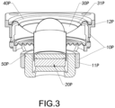
- the loudspeaker 100P includes a frame 10P, a magnetic circuit system 20P, a paper cone 30P, a suspension element 40P, and a voice coil 50P, wherein the magnetic circuit system 20P is mounted on a lower end portion 11P of the frame 10P, wherein outer and inner sides of the suspension element 40P are respectively extended to be connected to an upper end portion 12P of the frame 10P and an outer edge 31P of the paper cone 30P, so as to maintain the paper cone 30P on the upper end portion 12P of the frame 10P, wherein a voice coil lower end S 1P of the voice coil 50P and the magnetic circuit system 20P are magnetically coupled with each other, wherein a voice coil upper end 52P of the voice coil 50P is connected to the center of the paper cone 30P.
- the loudspeaker 100P has a central axis 101P, wherein a central axis of the paper cone 30P, a central axis of the suspension element 40P and a central axis of the voice coil 50P all coincide with the central axis 101P of the loudspeaker 100P.
- the paper cone 30P is centrally symmetric with respect to the central axis 101P of the loudspeaker 100P
- the suspension element 40P is centrally symmetric with respect to the central axis 101P of the loudspeaker 100P
- the voice coil 50P is centrally symmetric with respect to the central axis 101P of the loudspeaker 100P.
- the magnetic circuit system 20P and the voice coil 50P interact with each other to drive the paper cone 30P to reciprocate along the central axis 101P of the loudspeaker 100P, so that the paper cone 30P can agitate air, so as to generate sound waves, wherein the suspension element 40P is used to limit the stroke of the paper cone 30P to ensure the movement direction of the paper cone 30P.
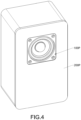
- Fig. 4 and Fig. 5 show a loudspeaker device according to the prior art, wherein the loudspeaker device includes a cabinet 200P and the loudspeaker 100P mounted on the cabinet 200P.
- the loudspeaker 100P is installed along a center line of a front baffle 201P of the cabinet 200P, so that the distances from the central axis 101P of the loudspeaker 100P to two side edges of the front baffle 201P are exactly equal, which will cause loudspeaker device diffraction at the edge of the cabinet 200P and affect the sound quality of the loudspeaker device.
- the loudspeaker devices in the prior art all adopt a method of designing a shape of the cabinet 200P, for example, the cabinet 200P is designed to be asymmetrical to avoid the distances from the central axis 101P of the loudspeaker 100P to the two side edges of the cabinet 200P being equal.
- This method not only requires the designer to have professional acoustic knowledge, but also causes the cabinet 200P to be unable to be designed into a regular shape.
- Fig. 6A shows a radiation state of a left reflected sound wave 1000P reflected by a left edge of the front baffle 201P of the cabinet 200P, wherein Fig.
- FIG. 6B shows a radiation state of a right side reflected sound wave 2000P reflected by a right edge of the plate 201P of the front baffle of the cabinet 200P, wherein Fig. 6C shows a radiation state of a composite sound wave 3000P formed after the left side reflected sound wave 1000P and the right side reflected sound wave 2000P encounter with each other.
- the peak of the left radiated sound wave 1000P appears at the same time with the peak of the right radiated sound wave 2000P, so the composite sound wave 3000P will suddenly overlap and seriously affect the sound quality of the loudspeaker device.
- the invention is advantageous in that it provides a loudspeaker and assembly method thereof, and vibration mechanism and loudspeaker device, wherein an induced position of a paper cone of the loudspeaker is deviated from a central axis of the loudspeaker, so that when the loudspeaker is installed to a front baffle of a cabinet, a loudspeaker device is formed by the cabinet and the loudspeaker, that can reduce or even avoid the sound diffraction problem and ensure the sound quality of the loudspeaker device.
- Another advantage of the invention is to provide a loudspeaker and assembly method thereof, vibration mechanism and loudspeaker device, wherein the induced position of the paper cone of the loudspeaker is deviated from the central axis of the loudspeaker, so that the loudspeaker device according to the present invention can reduce or even avoid the sound diffraction problem without needing a special design of the cabinet, so that designers who are not familiar with or even have no knowledge of acoustic expertise can easily design and create the loudspeaker device with a good sound quality.
- Another advantage of the invention is to provide a loudspeaker and assembly method thereof, vibration mechanism and loudspeaker device, wherein a connection position between a voice coil of the loudspeaker and a paper cone defines the induced position of the paper cone, and the voice coil is arranged to reciprocate along a moving axis of the loudspeaker, so as to induce the paper cone to reciprocate, wherein the moving axis of the loudspeaker deviates from the central axis of the loudspeaker.
- Another advantage of the invention is to provide a loudspeaker and assembly method thereof, vibration mechanism and loudspeaker device, wherein the moving axis of the loudspeaker passes through a center of gravity of a paper cone, so that when the voice coil induces the paper cone to reciprocate along the moving axis, the paper cone can be kept in a horizontal state to avoid deflection, so as to ensure the sound quality of the loudspeaker.
- Another advantage of the invention is to provide a loudspeaker and assembly method thereof, vibration mechanism and loudspeaker device, wherein the paper cone has an axis-near position and an axis-far position opposite to the axis-near position, wherein a thickness of the paper cone gradually becomes thinner from the axis-near position to the axis-far position, so that the moving axis of the loudspeaker passes through the center of gravity of the paper cone.
- Another advantage of the invention is to provide a loudspeaker and assembly method thereof, vibration mechanism and loudspeaker device, wherein a thickness of the suspension element of the loudspeaker gradually becomes thinner from a position of the suspension element corresponding to the axis-near position of the paper cone toward the position of the suspension element corresponding to the axis-far position of the paper cone, so that the moving axis of the loudspeaker can pass through a center of gravity of a vibration mechanism formed by the paper cone and the suspension element, so that the paper cone can be induced to move while the paper cone is kept to be horizontal.
- Another advantage of the present invention is to provide a loudspeaker and assembly method thereof, vibration mechanism and loudspeaker device, wherein a thickness of a glue layer for bonding the suspension element and the paper cone gradually becomes thinner from the axis-near position of the paper cone to the axis-far position of the paper cone, so that the moving axis of the loudspeaker can pass through the center of gravity of the vibration mechanism formed by the paper cone, the suspension element and the glue layer, so that the paper cone can be induced to move while the paper cone is kept to be horizontal.
- the present invention provides a loudspeaker comprising:
- the paper cone has an axis-near position and an axis-far position opposite to the axis-near position, wherein a thickness of the paper cone gradually becomes thinner from the axis-near position to the axis-far position.
- the paper cone has an axis-near position and an axis-far position opposite to the axis-near position, wherein a thickness of the suspension element gradually becomes thinner from a position of the suspension element corresponding to the axis-near position to another position of the suspension element corresponding to the axis-far position.
- the loudspeaker further comprises a glue layer attaching the suspension element inner side of the suspension element to the paper cone outer side of the paper cone, wherein a thickness of the glue layer gradually becomes thinner from the axis-near position of the paper cone to the axis-far position of the paper cone.
- the paper cone has an axis-near position and an axis-far position opposite to the axis-near position, wherein a thickness of the paper cone gradually becomes thinner from the axis-near position to the axis-far position, wherein a thickness of the suspension element gradually becomes thinner from a position of the suspension element corresponding to the axis-near position to another position of the suspension element corresponding to the axis-far position.
- the paper cone and the suspension element are integrally formed.
- the frame comprises a lower end frame and an upper end frame mounted to the lower end frame
- the lower end frame further comprises a magnetic circuit mounting ring, an engaging ring, and a plurality of connecting arms spacedly extended between the magnetic circuit mounting ring and the engaging ring, wherein a central axis of the magnetic circuit mounting ring and a central axis of the engaging ring deviate from each other
- the magnetic circuit system is mounted to the magnetic circuit mounting ring
- the upper end frame comprises a retaining ring and at least two engaging arms extended downward from the retaining ring, wherein the suspension element outer side of the suspension element is connected to the retaining ring of the upper end frame, wherein the at least two engaging arms of the upper end frame are mounted to the engaging ring of the lower end frame, wherein a central axis of the retaining ring and the central axis of the engaging ring coincide with each other.
- the loudspeaker further comprises an axis stabling element, wherein the axis stabling element has an axis stabling element inner side and an axis stabling element outer side opposite to the axis stabling element inner side, wherein the axis stabling element inner side of the axis stabling element is connected to the voice coil, wherein the axis stabling element outer side of the axis stabling element is connected to the frame.
- a shape of the paper cone is one of a horn-like structure and a flat plate-like structure.
- the present invention further provides a loudspeaker device comprising a cabinet and a loudspeaker, wherein the cabinet comprises a front baffle, wherein the loudspeaker is mounted to the front baffle of the cabinet, wherein the loudspeaker comprises:
- the paper cone has an axis-near position and an axis-far position opposite to the axis-near position, wherein a thickness of the paper cone gradually becomes thinner from the axis-near position to the axis-far position.
- the paper cone has an axis-near position and an axis-far position opposite to the axis-near position, wherein a thickness of the suspension element gradually becomes thinner from a position of the suspension element corresponding to the axis-near position to another position of the suspension element corresponding to the axis-far position.
- the loudspeaker further comprises a glue layer attaching the suspension element inner side of the suspension element to the paper cone outer side of the paper cone, wherein a thickness of the glue layer gradually becomes thinner from the axis-near position of the paper cone to the axis-far position of the paper cone.
- the paper cone has an axis-near position and an axis-far position opposite to the axis-near position, wherein a thickness of the paper cone gradually becomes thinner from the axis-near position to the axis-far position, wherein a thickness of the suspension element gradually becomes thinner from a position of the suspension element corresponding to the axis-near position to another position of the suspension element corresponding to the axis-far position.
- the paper cone and the suspension element are integrally formed.
- the frame comprises a lower end frame and an upper end frame mounted to the lower end frame
- the lower end frame further comprises a magnetic circuit mounting ring, an engaging ring, and a plurality of connecting arms spacedly extended between the magnetic circuit mounting ring and the engaging ring, wherein a central axis of the magnetic circuit mounting ring and a central axis of the engaging ring deviate from each other
- the magnetic circuit system is mounted to the magnetic circuit mounting ring
- the upper end frame comprises a retaining ring and at least two engaging arms extended downward from the retaining ring, wherein the suspension element outer side of the suspension element is connected to the retaining ring of the upper end frame, wherein the at least two engaging arms of the upper end frame are mounted to the engaging ring of the lower end frame, wherein a central axis of the retaining ring and the central axis of the engaging ring coincide with each other.
- the loudspeaker further comprises an axis stabling element, wherein the axis stabling element has an axis stabling element inner side and an axis stabling element outer side opposite to the axis stabling element inner side, wherein the axis stabling element inner side of the axis stabling element is connected to the voice coil, wherein the axis stabling element outer side of the axis stabling element is connected to the frame.
- a shape of the paper cone is one of a horn-like structure and a flat plate-like structure.
- the present invention further provides a method for assembling a loudspeaker, comprising the following steps:
- step (b) further comprises the following steps:
- the step (b) further comprises a following step: integrally forming the suspension element between the paper cone and the retaining ring of the upper end frame, wherein a thickness of the suspension element is gradually thinner from a position corresponding to an axis-near position of the paper cone to another position corresponding to an axis-far position of the paper cone.
- step (b) further comprises the following steps:
- the step (b) further comprises a following step: integrally forming the paper cone and the suspension element by injection molding, wherein the suspension element outer side of the suspension element is integrally connected to the retaining ring of the upper end frame, wherein a thickness of the paper cone gradually becomes thinner from an axis-near position to an axis-far position of the paper cone, wherein a thickness of the suspension element gradually becomes thinner from a position corresponding to the axis-near position of the paper cone to another position corresponding to the axis-far position of the paper cone.
- the present invention further provides a vibration mechanism, comprising:
- the paper cone has an axis-near position and an axis-far position opposite to the axis-near position, wherein the induced position of the paper cone is close to the axis-near position and away from the axis-far position.
- a center of gravity of the vibration mechanism is close to the axis-near position of the paper cone and away from the axis-far position of the paper cone.
- a thickness of the paper cone gradually becomes thinner from the axis-near position to the axis-far position.
- a thickness of the suspension element gradually becomes thinner from a position of the suspension element corresponding to the axis-near position to another position of the suspension element corresponding to the axis-far position.
- a thickness of the paper cone gradually becomes thinner from the axis-near position to the axis-far position, wherein a thickness of the suspension element gradually becomes thinner from a position of the suspension element corresponding to the axis-near position to another position of the suspension element corresponding to the axis-far position.
- the paper cone and the suspension element are integrally formed.
- the vibration mechanism further comprises a glue layer attaching the suspension element to the paper cone, wherein the glue layer is provided between the suspension element inner side of the suspension element and the paper cone outer side of the paper cone, wherein a thickness of the glue layer gradually becomes thinner from the axis-near position of the paper cone to the axis-far position of the paper cone.
- a shape of the paper cone is one of a horn-like structure and a flat plate-like structure.
- the term “a” should be understood as “at least one” or “one or more”. In other words, in one embodiment, the number of an element may be one, and in another embodiment, the number of the element may be plural. The term “one” should not be understood as a limitation on the number.
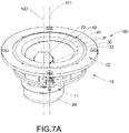
- a loudspeaker 100 according to a preferred embodiment of the present invention is disclosed and explained in the following description, wherein the loudspeaker 100 comprises a frame 10, a magnetic circuit system 20, a suspension element 30, a paper cone 40 and a voice coil 50.
- the frame 10 has a frame lower end 11 and a frame upper end 12 opposite to the frame lower end 11.
- the magnetic circuit system 20 has a magnetic gap 21 and a magnetic gap opening 22 communicating with the magnetic gap 21, wherein the magnetic circuit system 20 is mounted on the frame lower end 11 of the frame 10, and the magnetic gap opening 22 of the magnetic circuit system 20 faces to the frame upper end 12 of the frame 10.
- the paper cone 40 has a paper cone outer side 41.
- the suspension element 30 has a suspension element inner side 31 and a suspension element outer side 32 opposite to the suspension element inner side 31, wherein the suspension element inner side 31 of the suspension element 30 is extended inward, so as to be connected to the paper cone outer side 41 of the paper cone 40.
- the suspension element outer side 32 of the suspension element 30 is extended outward, so as to be connected to the frame upper end 12 of the frame 10, so that the paper cone 40 is held to the frame upper end 12 of the frame 10 with the help of the suspension element 30.
- the voice coil 50 has a voice coil lower end 51 and a voice coil upper end 52 opposite to the voice coil lower end 51, wherein the voice coil lower end 51 of the voice coil 50 passes through the magnetic gap opening 22 of the magnetic circuit system 20 and is extended into the magnetic gap 21 of the magnetic circuit system 20, and the voice coil lower end 51 of the voice coil 50 is movably held in the magnetic gap 21 of the magnetic circuit system 20.
- the voice coil lower end 51 of the voice coil 50 and the magnetic circuit system 20 are magnetically coupled with each other, so that the voice coil lower end 51 of the voice coil 50 and the magnetic circuit system 20 can interact with each other. Accordingly, the voice coil upper end 52 of the voice coil 50 is extended to and connected to the paper cone 40, so as to define an induced position 42 of the paper cone 40.
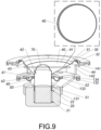
- the induced position 42 of the paper cone 40 deviates from a central axis 101 of the loudspeaker 100.
- a moving axis 102 of the loudspeaker 100 passes through the induced position 42 of the paper cone 40. In other words, the moving axis 102 of the loudspeaker 100 deviates from the central axis 101.
- the magnetic circuit system 20 and the voice coil lower end 51 of the voice coil 50 magnetically interact with each other, so as to allow the magnetic circuit system 20 to induce the paper cone 40 reciprocate along the moving axis 102 of the loudspeaker 100 through the voice coil 50 which drives the paper cone 40 at the induced position 42 of the paper cone 40, so as to agitate the air to outwardly radiate sound waves , wherein the suspension element 30 limits the stroke of the paper cone 40 and ensures that the paper cone 40 reciprocates along the moving axis 102 of the loudspeaker 100.
- the moving axis 102 of the loudspeaker 100 passes through the center of gravity of the paper cone 40, so that when the voice coil 50 drives the paper cone 40 at the induced position 42 of the paper cone 40, the paper cone 40 reciprocates along the moving axis 102 of the loudspeaker 100, and the paper cone 40 is capable of being retained horizontal, so as to avoid deviation, so as to ensure the sound quality of the loudspeaker 100.
- the paper cone 40 has an axis-near position 43 and an axis-far position 44 opposite to the axis-near position 43, wherein the axis-near position 43 of the paper cone 40 refers to an edge position of the paper cone outer side 41 of the paper cone 40 that is closest to the moving axis 102 of the loudspeaker 100.
- the axis-far position 44 refers to the edge position of the outer side 41 of the paper cone 40 that is farthest from the moving axis 102 of the loudspeaker 100.
- the thickness of the paper cone 40 gradually becomes thinner from the axis-near position 43 to the axis-far position 44, so that the center of gravity of the paper cone 40 is close to the axis-near position 44 and far from the axis-far position 43, so that the moving axis 102 of the loudspeaker 100 passes through the center of gravity of the paper cone 40.
- the voice coil 50 drives the paper cone 40 to reciprocate along the moving axis 102 of the loudspeaker 100, the paper cone 40 is retained horizontal, so as to avoid tilting, so as to ensure the sound quality of the loudspeaker 100.
- the frame 10 comprises a lower end frame 13 and an upper end frame 14 mounted on the lower end frame 13, wherein the lower end frame 13 forms the frame lower end 11 of the frame 10.
- the magnetic circuit system 20 is mounted on the lower end frame 13, so that the magnetic circuit system 20 is held at the frame lower end 11.
- the upper end frame 14 forms the frame upper end 12 of the frame 10.
- the suspension element outer side 32 of the suspension element 30 is connected to the upper end frame 14, so that the paper cone 40 connected with the suspension element 30 is held to the frame upper end 12.
- the lower end frame 13 further comprises a magnetic circuit mounting ring 131, an engaging ring 132, and a plurality of connecting arms 133 extended between the magnetic circuit mounting ring 131 and the engaging ring 132.
- the magnetic circuit mounting ring 131 of the lower end frame 13 is mounted to the magnetic circuit system 20 in such a manner that the magnetic circuit mounting ring 131 surrounds the outer side of the magnetic circuit system 20, so that the magnetic circuit system 20 is mounted to the lower frame 13.
- the central axis of the magnetic circuit mounting ring 131 and the central axis of the engaging ring 132 are deviated from each other and are not coincided with each other, so that the central axis of the magnetic circuit system 20 mounted on the magnetic circuit mounting ring 131 and the center axis of the engaging rings 132 are deviated from each other, and thus they are not coincided with each other.
- the upper end frame 14 comprises a retaining ring 141 and at least two engaging arms 142 extended downward from the retaining ring 141, wherein the suspension element outer side 32 of the suspension element 30 is connected to the retaining ring 141 of the upper end frame 14, so as to allow the retaining ring 141 to surround the paper cone 40.
- the engaging arms 142 of the upper end frame 14 are mounted to the engaging ring 132 of the lower end frame 13.
- the central axis of the retaining ring 141 of the upper end frame 14 and the central axis of the engaging ring 132 coincide with each other, so that the central axis of the magnetic circuit system 20 and the central axis of the retaining ring 141 deviate from each other, and thus they are not coincided with each other.
- the central axis of the retaining ring 141 of the upper end frame 14 and the central axis of the engaging ring 132 of the lower end frame 13 defines the central axis 101 of the loudspeaker 100.
- the central axis 101 of the loudspeaker 100, the central axis of the retaining ring 141 of the upper end frame 14, and the central axis of the engaging ring 132 of the lower end frame 13 coincide with each other.
- the central axis of the magnetic circuit system 20 defines the moving axis 102 of the loudspeaker 100, and the moving axis 102 of the loudspeaker 100 and the central axis of the magnetic circuit system 20 coincide with each other.
- the central axis of the magnetic circuit system 20 is deviated from the central axis of the retaining ring 141 of the upper end frame 14 and the central axis of the engaging ring 132 of the lower end frame 13, so that the moving axis 102 of the loudspeaker 100 deviates from the central axis 101 of the loudspeaker 100.
- the paper cone 40 can be formed by injection molding, so that the thickness of the paper cone 40 can gradually becomes thinner from the axis-near position 43 to the axis-far position 44.
- the forming method of the suspension element 30 is not limited in the present invention.
- the suspension element 30 is prefabricated, wherein the suspension element inner side 31 of the suspension element 30 can be attached to the paper cone outer side 41 of the paper cone 40 by an adhesive substance such as a glue.
- the suspension element outer side 32 of the suspension element 30 can be attached to the retaining ring 141 of the upper end frame 14 by an adhesive substance such as a glue.
- the suspension element 30 is integrally formed between the paper cone 40 and the retaining ring 141 of the upper end frame 14, so that the suspension element inner side 31 of the suspension element 30 is integrally connected to the paper cone outer side 41 of the paper cone 40 during the forming process of the suspension element 30, and the suspension element outer side 32 of the suspension element 30 is integrally connected to the retaining ring 141 of the upper end frame 14 during the forming process of the suspension element 30.
- the loudspeaker 100 further comprises an axis stabling element 60, wherein the axis stabling element 60 has an axis stabling element inner side 61 and an axis stabling element outer side 62 opposite to the axis stabling element inner side 61, wherein the axis stabling element inner side 61 of the axis stabling element 60 is extended to and connected to the voice coil 50, wherein the axis stabling element outer side 62 of the axis stabling element 60 is extended to and connected to the frame 10, wherein when the magnetic circuit system 20 induces the voice coil 50 to reciprocate along the moving axis 102 of the loudspeaker 100, the voice coil 50 can drive the axis stabling element 60 to deform, so as to restrict the reciprocating direction of the voice coil 50 with the help of the axis stabling element 60, and further prevent the moving direction of the voice coil 50 from deviating from the moving axis 102 of the loudspeaker 100.
- the lower end frame 13 comprises an engaging platform 134, wherein the engaging platform 134 is extended inward from the engaging ring 132, wherein the axis stabling element outer side 62 of the axis stabling element 60 is connected to the engaging platform 134 of the lower end frame 13 end.
- the shape of the axis stabling element 60 is not limited in the present invention.
- the axis stabling element 60 can be designed to have a shape similar to the suspension element 30.
- the axis stabling element 60 may have a cross-sectional shape of a "U”
- the axis stabling element 60 may have a cross-sectional shape of an "S”
- the axis stabling element 60 may have a cross-sectional shape of a wave
- the axis stabling element 60 may be a spider.
- the loudspeaker 100 further comprises a dust cap 70, wherein the dust cap 70 is installed on the voice coil upper end 52 of the voice coil 50 for sealing the upper end opening of the voice coil 50, so as to prevent dust from entering the interior of the voice coil 50.
- the shape of the dust cap 70 is not limited in the present invention, and it may be a hemispherical structure or a flat plate structure.
- the shape of the paper cone 40 is not limited in the present invention.
- the paper cone 40 has a horn-like structure, and in a loudspeaker 100 according to a first modified mode of the above preferred embodiment of the present invention, a paper cone 40 has a flat plate-like structure, as shown in Figs. 10 and 11 .
- Fig. 12 shows a loudspeaker 100B according to a second modified mode of the above preferred embodiment of the present invention. What is different from the loudspeaker 100 shown in Figs. 7A to 9 , in the loudspeaker 100 shown in Fig.
- the thickness of a paper cone 40 at each position is the same, wherein the thickness of a suspension element 30 is gradually thinner from the position corresponding to an axis-near position 43 of the paper cone 40 to the position of the suspension element 30 corresponding to the axis-far position 44 of the paper cone 40, so that the center of gravity of a vibration mechanism 103 formed by the suspension element 30 and the paper cone 40 is close to the axis-near position 43 of the paper cone 40, and is far from the axis-far position 44, so that a moving axis 102 of the loudspeaker 100 can pass through a center position of the vibration mechanism 103.
- the voice coil 50 drives the paper cone 40 to reciprocate along the moving axis 102 of the loudspeaker 100, the paper cone 40 can be kept horizontal and avoid tilting, so as to ensure the sound quality of the loudspeaker 100.
- the paper cone 40 can be made by injection molding process, or can be made by bending a flat structure and bonding the free end of the flat structure.
- Fig. 13 shows a loudspeaker 100 according to a third alternative mode of the above preferred embodiment of the present invention, what is different from the loudspeaker 100 shown in Figs. 7A to 9 , according to this alternative mode shown in Fig. 13 , the thickness of a paper cone 40 is the same at every position.
- the loudspeaker further comprises a glue layer 80 attaching the suspension element inner side 31 of the suspension element 30 to a paper cone outer side 41 of the paper cone 40, wherein the thickness of the glue layer 80 gradually becomes thinner from an axis-near position 43 to an axis-far position 44 of the paper cone 40, so that the center of gravity of a vibration mechanism 103 formed by the suspension element 30, the paper cone 40 and the glue layer 80 is close to the axis-near position 43 of the paper cone 40 and away from the axis-far position 44, so that a moving axis 102 of the loudspeaker 100 can pass through a center position of the vibration mechanism 103.
- the voice coil 50 drives the paper cone 40 to reciprocate along the moving axis 102 of the loudspeaker 100, the paper cone 40 can be kept horizontal and avoid tilting, so as to ensure the sound quality of the loudspeaker 100.
- the paper cone 40 can be made by injection molding process, or can be made by bending a flat structure and bonding the free end of the flat structure, wherein the suspension element 30 needs to be prefabricated.
- the present invention further provides an assembling method of the loudspeaker 100, wherein the assembling method comprises the following steps:
- step (b) further comprises the following steps:
- the step (b) further comprises the following step: integrally forming the suspension element 30 between the paper cone 40 and the retaining ring 141 of the upper end frame 14, wherein the thickness of the suspension element 30 is gradually becoming thinner from the position corresponding to the axis-near position 43 of the paper cone 40 to the position corresponding to the axis-far position 44 of the paper cone 40.
- step (b) further comprises the following steps:
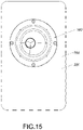
- Figs. 14 to 17C show a loudspeaker device according to a preferred embodiment of the present invention, wherein the loudspeaker device comprises the loudspeaker 100 and a cabinet 200, wherein the cabinet 200 comprises a front baffle 201.
- the loudspeaker 200 is installed on the front baffle 201 of the cabinet 200.
- the induced position 42 of the paper cone 40 of the loudspeaker 100 is deviated from the center axis of the loudspeaker 100.
- the cabinet 200 will not be equidistant on two sides of the moving axis 102 of the loudspeaker 100, so as to effectively reduce or even avoid diffracting and further ensure the sound quality of the loudspeaker device.
- the loudspeaker device can reduce or even avoid the sound diffraction problem without needing a special designing of the cabinet 200, so that designers who are not familiar with or even have no knowledge of acoustic expertise can easily design and create the loudspeaker device having good sound quality.
- the crests and troughs of the left reflected sound wave 1000 and the crests and troughs of the right reflected sound wave 2000 will be staggered to avoid excessive superposition between the left reflected sound wave 1000 and the right reflected sound wave 2000, so as to reduce or even avoid sound diffraction.
Landscapes
- Engineering & Computer Science (AREA)
- Physics & Mathematics (AREA)
- Acoustics & Sound (AREA)
- Signal Processing (AREA)
- Manufacturing & Machinery (AREA)
- Multimedia (AREA)
- Diaphragms For Electromechanical Transducers (AREA)
- Audible-Bandwidth Dynamoelectric Transducers Other Than Pickups (AREA)
Applications Claiming Priority (2)
| Application Number | Priority Date | Filing Date | Title |
|---|---|---|---|
| CN202010209085 | 2020-03-23 | ||
| PCT/CN2021/082416 WO2021190505A1 (zh) | 2020-03-23 | 2021-03-23 | 扬声器及其装配方法和振动机构以及音响装置 |
Publications (3)
| Publication Number | Publication Date |
|---|---|
| EP4132000A1 true EP4132000A1 (de) | 2023-02-08 |
| EP4132000A4 EP4132000A4 (de) | 2024-03-27 |
| EP4132000B1 EP4132000B1 (de) | 2026-05-20 |
Family
ID=77752894
Family Applications (1)
| Application Number | Title | Priority Date | Filing Date |
|---|---|---|---|
| EP21774366.5A Active EP4132000B1 (de) | 2020-03-23 | 2021-03-23 | Lautsprecher und lautsprechervorrichtung |
Country Status (5)
| Country | Link |
|---|---|
| US (1) | US12317049B2 (de) |
| EP (1) | EP4132000B1 (de) |
| JP (1) | JP7402990B2 (de) |
| CN (2) | CN113438591B (de) |
| WO (1) | WO2021190505A1 (de) |
Families Citing this family (1)
| Publication number | Priority date | Publication date | Assignee | Title |
|---|---|---|---|---|
| JP7402990B2 (ja) * | 2020-03-23 | 2023-12-21 | 寧波昇亜電子有限公司 | スピーカ、その組立方法、振動機構及び音響装置 |
Family Cites Families (13)
| Publication number | Priority date | Publication date | Assignee | Title |
|---|---|---|---|---|
| JPH02890U (de) * | 1988-06-10 | 1990-01-05 | ||
| JP3049936B2 (ja) * | 1992-05-07 | 2000-06-05 | 松下電器産業株式会社 | 楕円形スピーカ |
| JPH06153292A (ja) * | 1992-11-12 | 1994-05-31 | Showa Kogyo Kk | スピーカーのエッジ材料及びスピーカー用フリーエッジコーン |
| JP3405160B2 (ja) * | 1997-11-21 | 2003-05-12 | 日本ビクター株式会社 | スピーカ用偏心コーン、その製造方法及びその偏心コーンを組み込んだ偏心スピーカ |
| CN2371751Y (zh) * | 1999-01-06 | 2000-03-29 | 龙岗区布吉镇国泰乐仕音响厂 | 扬声器 |
| US7548631B2 (en) * | 2000-01-19 | 2009-06-16 | Harman International Industries, Incorporated | Speaker surround structure for maximizing cone diameter |
| US20060165253A1 (en) * | 2005-01-21 | 2006-07-27 | Hiroshi Ohara | Drum paper of loudspeaker covered with metallic layer |
| JP2010109665A (ja) * | 2008-10-30 | 2010-05-13 | Onkyo Corp | 偏心コーン形振動板を備える動電型スピーカー |
| JP5029709B2 (ja) * | 2010-02-04 | 2012-09-19 | パナソニック株式会社 | スピーカ |
| CN103079156B (zh) * | 2013-02-04 | 2015-05-13 | 东星电声科技(东莞)有限公司 | 一种超薄型喇叭 |
| CN115297415A (zh) * | 2017-12-31 | 2022-11-04 | 宁波升亚电子有限公司 | 扬声器及其弹波和应用 |
| CN209435416U (zh) * | 2018-12-24 | 2019-09-24 | 苏州井利电子股份有限公司 | 一种偏心扬声器 |
| JP7402990B2 (ja) * | 2020-03-23 | 2023-12-21 | 寧波昇亜電子有限公司 | スピーカ、その組立方法、振動機構及び音響装置 |
-
2021
- 2021-03-23 JP JP2022538428A patent/JP7402990B2/ja active Active
- 2021-03-23 WO PCT/CN2021/082416 patent/WO2021190505A1/zh not_active Ceased
- 2021-03-23 CN CN202110309892.3A patent/CN113438591B/zh active Active
- 2021-03-23 CN CN202120600275.4U patent/CN215581712U/zh not_active Withdrawn - After Issue
- 2021-03-23 EP EP21774366.5A patent/EP4132000B1/de active Active
- 2021-03-23 US US17/905,818 patent/US12317049B2/en active Active
Also Published As
| Publication number | Publication date |
|---|---|
| CN215581712U (zh) | 2022-01-18 |
| US20230156407A1 (en) | 2023-05-18 |
| WO2021190505A1 (zh) | 2021-09-30 |
| JP2023507219A (ja) | 2023-02-21 |
| EP4132000B1 (de) | 2026-05-20 |
| CN113438591A (zh) | 2021-09-24 |
| US12317049B2 (en) | 2025-05-27 |
| EP4132000A4 (de) | 2024-03-27 |
| JP7402990B2 (ja) | 2023-12-21 |
| CN113438591B (zh) | 2025-07-29 |
Similar Documents
| Publication | Publication Date | Title |
|---|---|---|
| CN115175069A (zh) | 动圈式扬声器 | |
| KR101726431B1 (ko) | 스피커 모듈 | |
| CN105323665B (zh) | 用于优化压缩驱动器中的调相插塞性能的孔型和定向 | |
| US12167217B2 (en) | Electro-acoustic transducer diaphragm with integrated structural features, and related systems and methods | |
| JP7789434B2 (ja) | スピーカー | |
| KR102266425B1 (ko) | 사각 형상의 마이크로 스피커 | |
| US10142736B2 (en) | Electroacoustic transducer | |
| KR20170134302A (ko) | 박형 스피커 | |
| CN119364267A (zh) | 发声装置和电子设备 | |
| CN107614875B (zh) | 泵 | |
| US12317049B2 (en) | Loudspeaker and assembly method therefor, vibration mechanism, and loudspeaker device | |
| CN111357301B (zh) | 振动板、以及具有该振动板的电声换能器 | |
| CN107950035A (zh) | 线性声学换能器 | |
| CN108696808A (zh) | 扬声器及扬声器装配方法 | |
| JP2013102409A (ja) | スピーカシステムとパッシブラジエータユニット | |
| CN102273231B (zh) | 多功能微型扬声器 | |
| CN119299930A (zh) | 发声装置和电子设备 | |
| CN112689226A (zh) | 微型扬声器 | |
| CN211321495U (zh) | 扬声器 | |
| CN113099360B (zh) | 扬声器及其装配方法 | |
| WO2007075674A2 (en) | Linear array transducer and methods of manufacture | |
| CN213934346U (zh) | 一种小体积的光路调整机构 | |
| TW202404380A (zh) | 動圈式揚聲器 | |
| JP2006311156A (ja) | 電気音響変換器 | |
| CN119450310A (zh) | 偏轴同轴扬声器及其装配方法 |
Legal Events
| Date | Code | Title | Description |
|---|---|---|---|
| STAA | Information on the status of an ep patent application or granted ep patent |
Free format text: STATUS: THE INTERNATIONAL PUBLICATION HAS BEEN MADE |
|
| PUAI | Public reference made under article 153(3) epc to a published international application that has entered the european phase |
Free format text: ORIGINAL CODE: 0009012 |
|
| STAA | Information on the status of an ep patent application or granted ep patent |
Free format text: STATUS: REQUEST FOR EXAMINATION WAS MADE |
|
| 17P | Request for examination filed |
Effective date: 20220923 |
|
| AK | Designated contracting states |
Kind code of ref document: A1 Designated state(s): AL AT BE BG CH CY CZ DE DK EE ES FI FR GB GR HR HU IE IS IT LI LT LU LV MC MK MT NL NO PL PT RO RS SE SI SK SM TR |
|
| DAV | Request for validation of the european patent (deleted) | ||
| DAX | Request for extension of the european patent (deleted) | ||
| REG | Reference to a national code |
Ref country code: DE Ref legal event code: R079 Free format text: PREVIOUS MAIN CLASS: H04R0003100000 Ipc: H04R0009040000 Ref country code: DE Ref legal event code: R079 Ref document number: 602021054606 Country of ref document: DE Free format text: PREVIOUS MAIN CLASS: H04R0003100000 Ipc: H04R0009040000 |
|
| RIC1 | Information provided on ipc code assigned before grant |
Ipc: H04R 9/02 20060101ALN20231124BHEP Ipc: H04R 7/20 20060101ALN20231124BHEP Ipc: H04R 7/12 20060101ALN20231124BHEP Ipc: H04R 1/22 20060101ALN20231124BHEP Ipc: H04R 1/02 20060101ALN20231124BHEP Ipc: H04R 31/00 20060101ALI20231124BHEP Ipc: H04R 9/06 20060101ALI20231124BHEP Ipc: H04R 9/04 20060101AFI20231124BHEP |
|
| STAA | Information on the status of an ep patent application or granted ep patent |
Free format text: STATUS: EXAMINATION IS IN PROGRESS |
|
| A4 | Supplementary search report drawn up and despatched |
Effective date: 20240222 |
|
| RIC1 | Information provided on ipc code assigned before grant |
Ipc: H04R 9/02 20060101ALN20240216BHEP Ipc: H04R 7/20 20060101ALN20240216BHEP Ipc: H04R 7/12 20060101ALN20240216BHEP Ipc: H04R 1/22 20060101ALN20240216BHEP Ipc: H04R 1/02 20060101ALN20240216BHEP Ipc: H04R 31/00 20060101ALI20240216BHEP Ipc: H04R 9/06 20060101ALI20240216BHEP Ipc: H04R 9/04 20060101AFI20240216BHEP |
|
| 17Q | First examination report despatched |
Effective date: 20240305 |
|
| GRAP | Despatch of communication of intention to grant a patent |
Free format text: ORIGINAL CODE: EPIDOSNIGR1 |
|
| STAA | Information on the status of an ep patent application or granted ep patent |
Free format text: STATUS: GRANT OF PATENT IS INTENDED |
|
| RIC1 | Information provided on ipc code assigned before grant |
Ipc: H04R 9/04 20060101AFI20251029BHEP Ipc: H04R 9/06 20060101ALI20251029BHEP Ipc: H04R 31/00 20060101ALI20251029BHEP Ipc: H04R 1/02 20060101ALN20251029BHEP Ipc: H04R 1/22 20060101ALN20251029BHEP Ipc: H04R 7/12 20060101ALN20251029BHEP Ipc: H04R 7/20 20060101ALN20251029BHEP Ipc: H04R 9/02 20060101ALN20251029BHEP |
|
| RIC1 | Information provided on ipc code assigned before grant |
Ipc: H04R 9/04 20060101AFI20251103BHEP Ipc: H04R 9/06 20060101ALI20251103BHEP Ipc: H04R 31/00 20060101ALI20251103BHEP Ipc: H04R 1/02 20060101ALN20251103BHEP Ipc: H04R 1/22 20060101ALN20251103BHEP Ipc: H04R 7/12 20060101ALN20251103BHEP Ipc: H04R 7/20 20060101ALN20251103BHEP Ipc: H04R 9/02 20060101ALN20251103BHEP |
|
| INTG | Intention to grant announced |
Effective date: 20251112 |
|
| GRAS | Grant fee paid |
Free format text: ORIGINAL CODE: EPIDOSNIGR3 |
|
| RAP3 | Party data changed (applicant data changed or rights of an application transferred) |
Owner name: TANG BAND INDUSTRIES CO., LTD. |
|
| GRAA | (expected) grant |
Free format text: ORIGINAL CODE: 0009210 |
|
| STAA | Information on the status of an ep patent application or granted ep patent |
Free format text: STATUS: THE PATENT HAS BEEN GRANTED |