EP4132061A1 - Procédé et dispositif de détection de canal de commande, et terminal, station de base et support de stockage - Google Patents
Procédé et dispositif de détection de canal de commande, et terminal, station de base et support de stockage Download PDFInfo
- Publication number
- EP4132061A1 EP4132061A1 EP21780717.1A EP21780717A EP4132061A1 EP 4132061 A1 EP4132061 A1 EP 4132061A1 EP 21780717 A EP21780717 A EP 21780717A EP 4132061 A1 EP4132061 A1 EP 4132061A1
- Authority
- EP
- European Patent Office
- Prior art keywords
- monitoring
- slot group
- control channel
- configuration information
- scs
- Prior art date
- Legal status (The legal status is an assumption and is not a legal conclusion. Google has not performed a legal analysis and makes no representation as to the accuracy of the status listed.)
- Pending
Links
Images


Classifications
-
- H—ELECTRICITY
- H04—ELECTRIC COMMUNICATION TECHNIQUE
- H04W—WIRELESS COMMUNICATION NETWORKS
- H04W24/00—Supervisory, monitoring or testing arrangements
- H04W24/02—Arrangements for optimising operational condition
-
- H—ELECTRICITY
- H04—ELECTRIC COMMUNICATION TECHNIQUE
- H04W—WIRELESS COMMUNICATION NETWORKS
- H04W72/00—Local resource management
- H04W72/20—Control channels or signalling for resource management
- H04W72/23—Control channels or signalling for resource management in the downlink direction of a wireless link, i.e. towards a terminal
-
- H—ELECTRICITY
- H04—ELECTRIC COMMUNICATION TECHNIQUE
- H04L—TRANSMISSION OF DIGITAL INFORMATION, e.g. TELEGRAPHIC COMMUNICATION
- H04L5/00—Arrangements affording multiple use of the transmission path
- H04L5/003—Arrangements for allocating sub-channels of the transmission path
- H04L5/0053—Allocation of signalling, i.e. of overhead other than pilot signals
-
- H—ELECTRICITY
- H04—ELECTRIC COMMUNICATION TECHNIQUE
- H04W—WIRELESS COMMUNICATION NETWORKS
- H04W72/00—Local resource management
- H04W72/04—Wireless resource allocation
- H04W72/044—Wireless resource allocation based on the type of the allocated resource
- H04W72/0446—Resources in time domain, e.g. slots or frames
Definitions
- the present disclosure relates to the field of communication, and in particular, to a method and a device for monitoring control channels, a terminal, a base station and a storage medium.
- the base station Before conducting a data communication between a base station and a terminal, the base station should transmit a scheduling signaling to the terminal.
- the scheduling signaling is transmitted on a physical downlink control channel (PDCCH).
- PDCCH physical downlink control channel
- One base station will serve a plurality of terminals and downlink channel quality is changeable, and then in order to realize a flexible scheduling of the base station, it is stipulated in the related protocol that the terminal should monitor a plurality of PDCCH candidates in each slot.
- the more PDCCH candidates to be monitored by the terminal the more flexible the base station scheduling is, and the capability of the terminal to monitor channels will be required to be stronger, which will cause a problem of a balance between the flexibility in the base station scheduling and the monitoring capability for a terminal.
- the slot length becomes smaller, which will cause that the terminal fails to complete the process of receiving and configuring a control signaling in the corresponding slot.
- embodiments of the present disclosure provide a method and a device for monitoring control channels, a terminal, a base station and a storage medium.
- An embodiment of the present disclosure provides a method for monitoring control channels, performed by a terminal, including:
- the specified slot condition includes that a sub-carrier spacing (SCS) is greater than 120 KHz; and the sharing control channel monitoring capability is used for characterizing a control channel monitoring capability corresponding to more than one slots.
- the determining a monitoring slot group for control channel monitoring includes:
- the first configuration information includes at least one of:
- the first configuration information further satisfies at least one of:
- the number of slots is 4 in case that the SCS is 480 KHz; and the number of slots is 8 in case that the SCS is 960 KHz.
- the number of slots is determined based on a ratio of the SCS to a preset reference SCS.
- the monitoring control channels indicated by the search space includes: monitoring the control channels indicated by the search space when a number of control channels to be monitored is not greater than the maximum number of control channel candidates.
- the determining the search space of the monitoring slot group includes:
- the second configuration information includes:
- the second configuration information further includes: an offset of start position of the monitoring slot group, where the offset of start position is used for indicating respective slots included in the monitoring slot group.
- the monitoring control channels indicated by the search space includes: monitoring control channels at one designated slot or the plurality of designated slots in the monitoring slot group.
- the method further includes: receiving or transmitting a shared data channel according to the one or more monitored control information after the control channel monitoring within all search spaces in the monitoring slot group has been completed.
- An embodiment of the present disclosure provides a method for monitoring control channels, performed by a base station, including:
- the specified slot condition includes that a sub-carrier spacing (SCS) is greater than 120 KHz; and the sharing control channel monitoring capability is used for characterizing a control channel monitoring capability corresponding to more than one slots.
- the determining a monitoring slot group for control channel monitoring includes:
- the first configuration information includes at least one of:
- the first configuration information further satisfies at least one of:
- the number of slots is 4 in case that the SCS is 480 KHz; and the number of slots is 8 in case that the SCS is 960 KHz.
- the number of slots is determined based on a ratio of the SCS to a preset reference SCS.
- the determining the search space of the monitoring slot group includes:
- the second configuration information includes:
- the second configuration information further includes: an offset of start position of the monitoring slot group, where the offset of start position is used for indicating respective slots included in the monitoring slot group.
- the transmitting the control channels indicated by the search space includes: transmitting the control channel at one designated slot or the plurality of designated slots within the monitoring slot group.
- the transmitting the control channels indicated by the search space includes: transmitting a control information within one or more search spaces in the monitoring slot group for indicating the terminal to receive or transmit a shared data channel according to one or more monitored control information after the control channel monitoring within all search spaces in the monitoring slot group has been completed.
- An embodiment of the present disclosure provides a device for monitoring control channels, applied to a terminal, including:
- An embodiment of the present disclosure provides a device for monitoring control channels, applied to a base station, including:
- An embodiment of the present disclosure provides a terminal, including a processor and a memory storing a program that is executable by the processor, where the program, when executed by the processor, causes the processor to perform the following steps of:
- the specified slot condition includes that a sub-carrier spacing (SCS) is greater than 120 KHz; and the sharing control channel monitoring capability is used for characterizing a control channel monitoring capability corresponding to more than one slots.
- SCS sub-carrier spacing
- the determining a monitoring slot group for control channel monitoring includes:
- the first configuration information includes at least one of:
- the monitoring control channels indicated by the search space includes: monitoring the control channels indicated by the search space when a number of control channels to be monitored is not greater than the maximum number of control channel candidates.
- the determining the search space of the monitoring slot group includes:
- the second configuration information includes:
- the second configuration information further includes: an offset of start position of the monitoring slot group, where the offset of start position is used for indicating respective slots included in the monitoring slot group.
- the monitoring control channels indicated by the search space includes: monitoring the control channels at one designated slot or the plurality of designated slots in the monitoring slot group.
- the processor further performs the step of: receiving or transmitting a shared data channel according to the one or more monitored control information after the control channel monitoring within all search spaces in the monitoring slot group has been completed.
- An embodiment of the present disclosure provides a base station, including a memory, a processor and a memory storing a program that is executable by the processor, where the program, when executed by the processor, causes the processor to perform the following steps:
- the specified slot condition includes that a sub-carrier spacing (SCS) is greater than 120 KHz; the sharing control channel monitoring capability is used for characterizing a control channel monitoring capability corresponding to more than one slots.
- the determining a monitoring slot group for control channel monitoring includes:
- the first configuration information includes at least one of:
- the determining the search space of the monitoring slot group includes:
- the second configuration information includes:
- the second configuration information further includes: an offset of start position of the monitoring slot group, where the offset of start position is used for indicating respective slots included in the monitoring slot group.
- the transmitting the control channels indicated by the search space includes: transmitting the control channels at one designated slot or the plurality of designated slots in the monitoring slot group.
- the transmitting the control channels indicated by the search space includes: transmitting a control information within one or more search spaces in the monitoring slot group for indicating the terminal to receive or transmit a shared data channel according to one or more monitored control information after the control channel monitoring within all search spaces in the monitoring slot group has been completed.
- An embodiment of the present disclosure provides a non-transitory computer-readable storage medium storing a computer program that, when executed by a processor, causes the processor to perform the steps of the above method for monitoring control channels performed by a terminal.
- An embodiment of the present disclosure provides a non-transitory computer-readable storage medium storing a computer program that, when executed by a processor, causes the processor to perform the steps of the above method for monitoring control channels performed by a base station.
- An embodiment of the present disclosure provides a method and a device for monitoring control channels, a terminal, a base station and a storage medium.
- the base station Before conducting a data communication between a base station and a terminal, the base station should transmit a scheduling signaling to the terminal.
- the scheduling signaling is transmitted on a physical downlink control channel (PDCCH).
- PDCCH physical downlink control channel
- One base station will serve a plurality of terminals and downlink channel quality is changeable, and then in order to realize a flexible scheduling of the base station, it is stipulated in the related protocol that the terminal should monitor a plurality of PDCCH candidates in each slot.
- the more PDCCH candidates to be monitored by the terminal the more flexible the base station scheduling is, and the capability of the terminal to monitor channels will be required to be stronger, which will cause a problem of a balance between the flexibility in the base station scheduling and the monitoring capability for a terminal.
- the number of PDCCH candidates to be monitored by the terminal in each slot with SCS below 120 KHz is defined in the current standard. In case of the SCS is greater than 120 KHz, there is no better optimization solution about defining the capability of monitoring the number of PDCCH candidates by the terminal. (1) PDCCH candidate.
- the PDCCH is used to transmit downlink control information (DCI), and the transmitted information includes common control information and user-specific control information.
- DCI downlink control information
- CORESET control resource set
- NR new radio
- the CORESET is used for characterizing the size of the PDCCH resource block.
- a CORESET consists of several control channel elements (CCEs). Every 6 CCEs constitute a resource element group (REG). Each REG includes a resource block (RB).
- CCEs control channel elements
- REG resource element group
- RB resource block
- a CORESET includes a plurality of PDCCH candidates to be monitored by a terminal.
- any one or more CCEs can constitute PDCCH candidates. It is agreed in the current standard that a PDCCH consisting of 1 CCE is called as PDCCH candidates with a CCE aggregation level of 1; a PDCCH consisting of 2 CCEs is called as PDCCH candidates with a CCE aggregation level of 2; and a PDCCH consisting of 4 CCEs is called as PDCCH candidates with a CCE aggregation level of 4, and so on.
- the CCE aggregation levels supported by the current standard protocol are: 1, 2, 4, 8 and 16.
- a CORESET there will be a plurality of PDCCH candidates with the same CCE aggregation level, and the number specified by the current standard protocol is 0, 1, 2, 3, 4, 5, 6 and 8.
- the number of PDCCH candidates for a broadcast channel and the CCE aggregation levels are shown in table 1.
- Table 1 CCE aggregation levels the number of PDCCH candidates 4 4 8 2 16 1
- the search space defines a time range in which the terminal needs to monitor PDCCH.
- the search space includes a common search space (CSS) and a user equipment specific search space (USS). CSS refers to the search space in which all terminals or a group of terminals need to monitor PDCCH; while USS is the search space in which only a certain terminal individually configured by a base station needs to monitor PDCCH.
- CSS refers to the search space in which all terminals or a group of terminals need to monitor PDCCH
- USS is the search space in which only a certain terminal individually configured by a base station needs to monitor PDCCH.
- a first number of control channel candidates to be monitored is denoted as M PDCCH css .
- a second number of control channel candidates to be monitored is denoted as M PDCCH uss .
- M PDCCH max , slot , ⁇ of PDCCH candidates to be monitored is the sum of the first number and the second number, and does not exceed a certain threshold.
- the monitoring capability determined by the current standard protocol is shown in table 2.
- Table 2 ⁇ M PDDCH max , slot , ⁇ Remark 0 44 SCS 15 KHz 1 36
- SCS 30 KHz 2 22
- SCS 60 KHz 3 20
- SCS 120 KHz
- C PDCCH css a first number of CCEs required to satisfy the number of the above control channel candidates to be monitored.
- C PDCCH uss a second number of CCEs required to satisfy the number of the above control channel candidates to be monitored.
- the total number C PDCCH max , slot , ⁇ of CCEs is the sum of the first number of CCEs and the second number of CCEs, and does not exceed a certain threshold.
- the number of PDCCH candidates to be monitored and the number of CCEs defined in a current NR protocol are in units of slots. That is, the terminal need to perform a blind monitoring for PDCCH in units of slots, and then the terminal receives physical downlink shared channel (PDSCH) data or transmits physical uplink shared channel (PUSCH) data according to the monitored DCI content.
- PDSCH physical downlink shared channel
- PUSCH physical uplink shared channel
- the base station when the base station schedules the terminal to receive one PDSCH, the base station first transmits scheduling information or DCI on a PDCCH, where the DCI indicates the time domain/frequency domain information, the modulation and coding rate and other information of PDSCH.
- the terminal monitors the PDCCH at the appointed slot position (the appointed slot is configured by the base station), parses the DCI content, configures receiving parameters of PDSCH according to the parsed DCI content, and the PDSCH demodulating & decoding module is configured to demodulate and decode PDSCH according to the configuration information.
- the time spent by a PDCCH receiving and monitoring module is t1; the time spent by the PDCCH receiving and monitoring module to transmit the monitored DCI information to a DCI parsing module is t2; the time spent by the DCI parsing module is t3; the time spent by the DCI parsing module to transmit PDSCH configuration information to the PDSCH demodulating & decoding module is t4; and the time spent by the PDSCH demodulating & decoding module is t5.
- the slot length is greater than or equal to 0.125ms.
- the configuration processes of PDCCH monitoring, DCI analysis and PDSCH scheduling information can be completed within 0.125ms.
- the slot length becomes smaller, and it is difficult for the terminal to complete the process of receiving and configuring a control signaling in the corresponding slot due to the following reasons.
- an embodiment of the present disclosure provides a method and a device for monitoring control channels, a terminal, a base station and a storage medium, to meet the needs of the development of wireless communication.
- the method and the device for monitoring the control channel, the terminal, the base station and the storage medium according to the embodiments of the present disclosure can be applied to a wireless communication system or a wireless and wired system, which includes, but not limited to, 5G systems (such as NR systems), 6G systems, satellite systems, car networking systems, long term evolution (LTE) systems, subsequent evolution communication systems of the above systems and the like.
- 5G systems such as NR systems
- 6G systems such as NR systems
- satellite systems such as NR systems
- LTE long term evolution
- the base station may include, but not limited to, one or more of the following: a commonly used base station, an evolved node base station (eNB), a network-side device in a 5G system (for example, a next-generation base station (gNB), transmission and reception point (TRP)) or other equipment.
- a commonly used base station for example, an evolved node base station (eNB), a network-side device in a 5G system (for example, a next-generation base station (gNB), transmission and reception point (TRP)) or other equipment.
- eNB evolved node base station
- gNB next-generation base station
- TRP transmission and reception point
- the terminal may be referred to as user equipment (UE).
- UE includes, but not limited to, handheld devices and vehicle-mounted devices.
- UE may be a mobile phone, a tablet computer, a notebook computer, an ultra-mobile personal computer (UMPC), a netbook, or a personal digital assistant (PDA), etc.
- UMPC ultra-mobile personal computer
- PDA personal digital assistant
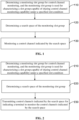
- FIG. 1 is a flowchart of a method for monitoring control channels according to embodiments of the present disclosure, and the method for monitoring the control channel can be performed by a terminal.
- the method for monitoring the control channels may include the following steps: Step 110, determining a monitoring slot group for control channel monitoring, and the monitoring slot group is used for characterizing a slot group capable of sharing control channel monitoring capability under a specified slot condition.
- the sharing control channel monitoring capability may refer to that the control channel monitoring capability is based on a slot group, for example, more than one slots correspond to one control channel monitoring capability.
- control channel monitoring can be used in a traditional Uu interface; and it can also be used in a side link, i.e. direct link.
- the monitoring slot group may refer to a slot group consisting of more than one slots, and these slots share one control channel monitoring capability under a specified slot condition.
- control channel is PDCCH
- monitoring slot group for PDCCH monitoring includes more than one slots, and these slots share a PDCCH monitoring capability under a specified slot condition.
- the specified slot condition may be a specific value or a value range of the SCS set according to the actual situation.
- the specified slot condition is that the SCS is 120 KHz; or the specified slot condition is that the SCS is greater than 120 KHz.
- Step 120 determining a search space of the monitoring slot group.
- the search space may refer to the time range in which the control channel monitoring capability is configured in the monitoring slot group, which is the time range in which the terminal needs to monitor control channels, and the time range in which the base station needs to transmit the control channels.
- the search space in which the terminal needs to monitor the control channels and the search space in which the base station needs to transmit the control channel are the same, which can reduce the implementation complexity of the terminal.
- the type of the search space may be CSS or USS.
- the number of search spaces can be one or more.
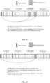
- SCS is 480 KHz; 4 slots form a monitoring slot group; the number of search spaces is 1; the search space is configured in slot 1 in the monitoring slot group; and no search space is configured in the other slots in the monitoring slot group.
- SCS is 960 KHz; 8 slots form a monitoring slot group; the number of search spaces is 2 which are respectively configured in slot 0 and slot 4.
- Step 130 monitoring the control channels indicated by the search space.
- the base station when the base station transmits control information on the control channel, it only transmits the control information indicated by the search space configured with the control channel monitoring capability in the monitoring slot group, and then the terminal can only monitor the control channels indicated by the search space configured with the control channel monitoring capability.
- the DCI when the base station transmits DCI on the PDCCH, the DCI is transmitted only on the slot 0 configured with the PDCCH monitoring capability in the monitoring slot group.
- Each DCI can schedule up to 4 PDSCH data or 4 PUSCH data.
- the terminal only monitors the PDCCH on the slot 0 configured with the PDCCH monitoring capability within the slot group, and configures and receives PDSCH or transmits PUSCH according to the monitored DCI.
- the PDSCH When the PDSCH is received, corresponding demodulation and decoding are required at the same time.
- the specified slot condition in the above step 110 may include that the SCS is greater than 120 KHz; the sharing control channel monitoring capability is used for characterizing one control channel monitoring capability corresponding to more than one slots.
- a slot group can be used as a unit, for example, more than one slots correspond to or share a same control channel monitoring capability, and the search space can be configured to realize the corresponding control channel monitoring.
- the corresponding or sharing control channel monitoring capability may refer to more than one slots in the same slot group correspond to a same control channel monitoring capability.
- the control channel is PDCCH
- the monitoring slot group for PDCCH monitoring includes more than one slots, and these slots correspond to a same PDCCH monitoring capability under a specified slot condition.
- control channels monitoring may be monitored in units of monitoring slot groups, that is, more than one slots correspond to a control channel monitoring capability, to avoid the problem that a terminal is unable to complete the process of receiving and configuring a control signaling in the corresponding slot due to the increase in the SCS, which meets the requirements of the development of wireless communication.
- determining the monitoring slot group for control channel monitoring is determined in step 110 may include the following steps (1-1-1) or (1-1-2).
- first configuration information for the monitoring slot group is determined according to an interface protocol between a first node and a second node, and the monitoring slot group is determined according to the first configuration information.
- the first node may be a base station, and the second node may be a terminal; or the first node may be a terminal, and the second node may be a base station. That is, the first configuration information for the monitoring slot group is determined according to the interface protocol between the base station and the terminal.
- the first configuration information indicated by a base station is received, and the monitoring slot group is determined according to the first configuration information.
- the first configuration information can be transmitted to the terminal by the base station through higher layer signaling, and then the first configuration information can be received by the terminal through higher layer signaling.
- the first configuration information for the monitoring slot group can be determined according to the interface protocol between the first node and the second node, and the monitoring slot group can be determined according to the first configuration information; or the first configuration information indicated by the base station can also be received, and the monitoring slot group can be determined according to the first configuration information, to enrich the acquisition method of the first configuration information, thereby improving the reliability of determining the monitoring slot group.
- the first configuration information in the above (1-1-1) or (1-1-2) may include:
- the number of slots is associated with the SCS, for example, if the SCS is 480 KHz, the number of slots is 4, and if the SCS is 960 KHz, the number of slots is 8. This is only for illustration, and the relationship between the number of slots and the SCS can be set based on requirements.
- the number of slots included in the monitoring slot group may be directly configured, for example, the number of slots is 5 or 4.
- the expansion factor can be 1, 2, or other values.
- the maximum number of control channel candidates is the maximum number of PDCCH candidates, which can be as M PDCCH max , slot , ⁇ shown in table 4.
- SCS 2 ⁇ ⁇ 15 KHz .
- SCS 240 KHz.
- the shared slot number is 2
- the maximum number of PDCCH candidates is M1.
- the shared slot number is 4, and the maximum number of PDCCH candidates is M2.
- SCS is 960 KHz
- the shared slot number is 8
- the maximum number of PDCCH candidates is M3.
- SCS is 1920 KHz
- the shared slot number is 16, and the maximum number of PDCCH candidates is M4.
- the above maximum number of CCEs can be as - C PDCCH max , slot , ⁇ shown in table 5.
- the shared slot number is 2, and the maximum number of CCEs is C1.
- the shared slot number is 4, and the maximum number of CCEs is C2.
- SCS is 960 KHz
- the shared slot number is 8, and the maximum number of CCEs is C3.
- SCS is 1920 KHz
- the shared slot number is 16, and the maximum number of CCEs is C4.
- the monitoring slot group can be determined according to the number of slots, the maximum number of control channel candidates, and the maximum number of CCEs in the first configuration information, to improve the accuracy of determining the monitoring slot group.
- the monitoring control channels indicated by the search space in step 130 may include the following step: (1-2-1), monitoring the control channels indicated by the search space when a number of control channels to be monitored is not greater than the maximum number of control channel candidates.
- the base station when the base station transmits the control channel, it should be ensured that the number of control channels to be transmitted is within the range of a "the maximum number of control channel candidates"; and correspondingly, when the control channels are monitored by the terminal, the control channel monitoring is only performed within the range of the "maximum number of control channel candidates".
- the number of control channel to be monitored is less than or equal to 20.
- control channels indicated by the search space are monitored when a number of control channels to be monitored is not greater than the maximum number of control channel candidates, to ensure that the control channel are monitored within the capability for the terminal, and reliability of the control channel monitoring is improved.
- determining the search space of the monitoring slot group in step 120 may include (1-3-1) or (1-3-2).
- second configuration information for the search space is determined according to an interface protocol between a first node and a second node, and the search space is determined according to the second configuration information.
- the first node may be a base station, and the second node may be a terminal; or the first node may be a terminal, and the second node may be a base station. That is, the second configuration information for the search space is determined according to the interface protocol between the base station and the terminal.
- the second configuration information indicated by a base station is received, and the search space is determined according to the second configuration information.
- the second configuration information can be transmitted to the terminal by the base station through higher layer signaling, and then the second configuration information can be received by the terminal through higher layer signaling.
- second configuration information for the search space is determined according to an interface protocol between a first node and a second node, and the search space is determined according to the second configuration information; or the second configuration information indicated by a base station is received, and the search space is determined according to the second configuration information, to enrich the acquisition method of the second configuration information, and then to improve the reliability of determining the search space.
- the second configuration information in the above (1-3-1) or (1-3-2) may include:
- the above-mentioned first indication information may indicate the slot groups with a monitoring occasion for control channel.
- a slot group is configured with a monitoring occasion, control channels are monitored in this slot group by the terminal. Otherwise, there is no need to monitor the control channels in this slot group.
- ⁇ 0, 1, 2, 3 ⁇ is a slot group with a control channel monitoring occasion
- ⁇ 8, 9, 10, 11 ⁇ is another slot group without a control channel monitoring occasion.
- the monitoring slot group with a control channel monitoring occasion may be indicated by the following two configuration ways.
- a first way is to use a bitmap.
- a value of 80 bit is used for indicating a configuration of 10ms (a slot group is 0.125ms, and 10ms contains 80 slot groups), 1 means that PDCCHs need to be monitored in the corresponding slot group, 0 means that PDCCHs do not need to be monitored in the corresponding slot group.
- a second way is to use a periodic manner whose configuration parameters include: slot group period, and slot group offset.
- the period of the search space is 4 slot groups (SG), and the offset is 2 SGs.
- the terminal monitors PDCCHs only on a SG with a period of 4 SGs and an offset of 2 SGs.
- the position of the control channel monitoring occasion at the monitoring slot group may refer to the position of the slot and the symbol where the control channel monitoring occasion is configured.
- ⁇ 0, 1, 2, 3 ⁇ is a slot group, where a control channel monitoring occasion is at slot 0.
- the second configuration information may include: an offset of start position of the monitoring slot group, and the offset of start position is used for indicating respective slots included in the monitoring slot group.
- the offset of start position is used for indicating which slots a slot group consists of.
- the serial numbers of slots included within the slot group are ⁇ 4n, 4n+1, 4n+2, 4n+3 ⁇ .
- n is an integer greater than or equal to 0.
- ⁇ 0, 1, 2, 3 ⁇ is a slot group
- ⁇ 8, 9, 10, 11 ⁇ is another slot group.
- the serial numbers of slots included within the slot group are ⁇ 4n+2, 4n+1+2, 4n+2+2, 4n+3+2 ⁇ .
- n is an integer greater than or equal to 0.
- ⁇ 2, 3, 4, 5 ⁇ is a slot group
- ⁇ 10, 11, 12, 13 ⁇ is another slot group.
- the offset of start position may be transmitted to the terminal by the base station through higher layer signaling.
- the base station transmits the control channels, it is ensured that the control channels are transmitted in the time domain "within the configured search space".
- the control channels are monitored only in the configured time domain by the terminal.
- the offset of start position is always 0, it can be used as a default setting without indication.
- step 130 when monitoring control channels indicated by the search space in step 130, it may include the following step.
- control channels are monitored at one designated slot or a plurality of designated slots in the monitoring slot group.
- the position where the control channel monitoring occasion is at the monitoring slot group may refer to the position of the slot and the symbol where the control channel monitoring occasion is configured.
- ⁇ 0, 1, 2, 3 ⁇ is a slot group where a control channel monitoring occasion is at slot 0, and the control channels can only be monitored at slot 0 by the terminal.
- ⁇ 0, 1, 2, 3 ⁇ is a slot group where the control channel monitoring occasions are at slot 0 and slot 3, and the control channels can be monitored at slot 0 and slot 3 by the terminal.
- control channel monitoring can be performed at the position where the control channel monitoring occasion is located in the monitoring slot group, to improve the efficiency of the control channel monitoring.
- step 130 it may further include the following step (1-5-1).
- a shared data channel is received or transmitted according to one or more monitored control information after the control channel monitoring within all search spaces in the monitoring slot group has been completed.
- the transmitting or receiving time is calculated according to the end time of the last search space.
- the preparation time required by data transmission is N2 (having a unit of a symbol or time)
- the end time of the CORESET of the last search space within the slot group is t2
- the terminal is not required to be capable of transmitting data before t2+N2.
- control channel monitoring can be used in a traditional Uu interface; it can also be used in a side link, i.e., direct link.
- the control information corresponding to the Uu interface is DCI; the control information corresponding to the side link is sidelink control information (SCI).
- PDSCH is received according to the monitored one or more DCIs after the PDCCH monitoring within all search spaces in the monitoring slot group has been completed.
- the PDCCH is used to transmit DCI control information.
- the physical sidelink shared channel (PSSCH) is received according to the monitored one or more SCIs after the PSCCH monitoring within all search spaces in the monitoring slot group has been completed.
- the PSCCH is used to transmit SCI control information.
- FIG. 2 is a flowchart of a method for monitoring control channels according to embodiments of the present disclosure, and the method can be performed by a base station. As shown in FIG. 2 , the method for monitoring the control channels may include the following steps.
- Step 210 determining a monitoring slot group for control channel monitoring, and the monitoring slot group is used for characterizing a slot group capable of sharing control channel monitoring capability under a specified slot condition.
- control channel monitoring can be used in a traditional Uu interface; and it can also be used in a side link, i.e., direct link.
- the monitoring slot group may refer to a slot group consisting of more than one slots, and these slots share control channel monitoring capability under a specified slot condition.
- control channel is PDCCH
- monitoring slot group for PDCCH monitoring includes more than one slots, and these slots share a PDCCH monitoring capability under a specified slot condition.
- the specified slot condition may be a specific value or a value range of the SCS set according to the actual situation.
- the specified slot condition is that the SCS is 120 KHz; or the specified slot condition is that the SCS is greater than 120 KHz.
- Step 220 determining a search space of the monitoring slot group.
- the search space may refer to the time range in which the control channel monitoring capability is configured in the monitoring slot group, and is the time range in which the terminal needs to monitor the control channels, and the time range in which the base station needs to transmit the control channel.
- the search space in which the terminal needs to monitor the control channels and the search space in which the base station needs to transmit the control channel are the same, which can reduce the implementation complexity of the terminal.
- the type of the search space may be CSS or USS.
- the number of search spaces can be one or more.
- SCS is 480 KHz; 4 slots form a monitoring slot group; the number of search spaces is 1; the search space is configured in slot 2 in the monitoring slot group; and no search space is configured in the other slots in the monitoring slot group.
- SCS is 960 KHz; 8 slots form a monitoring slot group; the number of search spaces is 2 which are respectively configured in slot 0 and slot 4.
- Step 230 transmitting control channels indicated by the search space for indicating a terminal to monitor the control channels indicated by the search space.
- the base station when the base station transmits control information on the control channel, it only transmits the control information indicated by the search space configured with the control channel monitoring capability in the monitoring slot group, and then the terminal can only perform control channel monitoring indicated by the search space configured with the control channel monitoring capability.
- the DCI when the base station transmits DCI on the PDCCH, the DCI is transmitted only on the slot 0 configured with the PDCCH monitoring capability in the monitoring slot group.
- Each DCI can schedule up to 4 PDSCH data.
- the terminal only monitors the PDCCH on the slot 0 configured with the PDCCH monitoring capability within the slot group, and configures, receives, demodulates and decodes PDSCH according to the monitored DCI.
- the specified slot condition in the above step 210 may include that the SCS is greater than 120 KHz; the sharing control channel monitoring capability is used for characterizing one control channel monitoring capability corresponding to more than one slots.
- a slot group can be used as a unit, for example, more than one slots correspond to or share a same control channel monitoring capability, and the search space can be configured to realize the corresponding control channel monitoring.
- the corresponding or sharing a control channel monitoring capability may refer to more than one slots in the same slot group sharing a same control channel monitoring capability.
- the control channel is PDCCH
- the monitoring slot group for PDCCH monitoring includes more than one slots, and these slots correspond to a same PDCCH monitoring capability under a specified slot condition.
- the control channel may be monitored in units of monitoring slot groups, that is, more than one slots correspond to a control channel monitoring capability, to avoid the problem that a terminal is unable to complete the process of receiving and configuring a control signaling in the corresponding slot due to the increase in the SCS, which meets the requirements of the development of wireless communication.
- determining the monitoring slot group for control channel monitoring in step 210 may include the following steps (2-1-1) or (2-1-2).
- first configuration information for the monitoring slot group is determined according to an interface protocol between a first node and a second node.
- the first node may be a base station, and the second node may be a terminal; or the first node may be a terminal, and the second node may be a base station. That is, the first configuration information for the monitoring slot group is determined according to the interface protocol between the base station and the terminal.
- the monitoring slot group is determined according to the first configuration information.
- the first configuration information for the monitoring slot group can be determined according to the interface protocol between the first node and the second node, and the monitoring slot group can be determined according to the first configuration information, to improve the reliability of determining the monitoring slot group.
- the first configuration information in the above (2-1-1) may include:
- the number of slots is 4; and if the SCS is 960 KHz, the number of slots is 8.
- the number of slots included in the monitoring slot group may be directly configured, for example, the number of slots is 5 or 4.
- the expansion factor can be 1, 2, or other values.
- the maximum number of control channel candidates is the maximum number of PDCCH candidates, which is as M PDCCH max , slot , ⁇ showed in the above table 4.
- the configuration of the maximum number of PDCCH candidates depends on the capability of the terminal.
- the maximum number of CCEs is as C PDCCH max , slot , ⁇ shown in the above table 5.
- the configuration of the maximum number of CCEs also depends on the capability of the terminal.
- the monitoring slot group can be determined according to the number of slots, the maximum number of control channel candidates, and the maximum number of CCEs in the first configuration information, to improve the accuracy of determining the monitoring slot group.
- determining the search space of the monitoring slot group in step 220 may include the following steps (2-2-1) or (2-2-2).
- second configuration information for the search space is determined according to an interface protocol between a first node and a second node.
- the first node may be a base station, and the second node may be a terminal; or the first node may be a terminal, and the second node may be a base station. That is, the second configuration information for the search space is determined according to the interface protocol between the base station and the terminal.
- the search space is determined according to the second configuration information. It can be seen from the above embodiments that the second configuration information for the search space is determined according to the interface protocol between the first node and the second node, and the search space is determined according to the second configuration information, to improve the reliability of determining the search space.
- the second configuration information in the above (2-2-1) may include:
- the above-mentioned first indication information may indicate the slot groups with a monitoring occasion for control channel.
- the control channels are monitored in this slot group by the terminal. Otherwise, there is no need to monitor the control channels in this slot group.
- ⁇ 0, 1, 2, 3 ⁇ is a slot group with a control channel monitoring occasion; and ⁇ 8, 9, 10, 11 ⁇ is another slot group without a control channel monitoring occasion.
- the monitoring slot group with a control channel monitoring occasion may be indicated by the following two configuration ways.
- a first way is to use a bitmap.
- a value of 80 bit is used for indicating a configuration of 10ms (a slot group is 0.125ms, and 10ms contains 80 slot groups), 1 means that PDCCHs need to be monitored in the corresponding slot group, 0 means that PDCCHs do not need to be monitored in the corresponding slot group.
- a second way is to use a periodic manner whose configuration parameters include: slot group period, and slot group offset.
- the period of the search space is 4 slot groups (Slot Group, SG), and the offset is 2 SGs.
- the terminal monitors PDCCHs only on a SG with a period of 4 SGs and an offset of 2 SGs.
- the position of the control channel monitoring occasion at the monitoring slot group may refer to the position of the slot and the symbol where the control channel monitoring occasion is configured.
- ⁇ 0, 1, 2, 3 ⁇ is a slot group, where a control channel monitoring occasion is at slot 0.
- the second configuration information may include: an offset of start position of the monitoring slot group, and the offset of start position is used for indicating respective slots included in the monitoring slot group.
- the offset of start position is used for indicating which slots a slot group consists of.
- the serial numbers of slots included within the slot group are ⁇ 4n, 4n+1, 4n+2, 4n+3 ⁇ .
- n is an integer greater than or equal to 0.
- ⁇ 0, 1, 2, 3 ⁇ is a slot group
- ⁇ 8, 9, 10, 11 ⁇ is another slot group.
- the serial numbers of slots included within the slot group are ⁇ 4n+2, 4n+1+2, 4n+2+2, 4n+3+2 ⁇ .
- n is an integer greater than or equal to 0.
- ⁇ 2, 3, 4, 5 ⁇ is a slot group
- ⁇ 10, 11, 12, 13 ⁇ is another slot group.
- the offset of start position may be transmitted to the terminal by the base station through higher layer signaling.
- the base station transmits the control channel, it is ensured that the control channel is transmitted in the time domain "within the configured search space".
- control channel monitoring is only performed in the configured time domain by the terminal.
- the offset of start position is always 0, it can be used as a default setting without indication.
- transmitting the control channels indicated by the search space in step 230 may include: transmitting the control channel on one designated slot or a plurality of designated slots in the monitoring slot group.
- ⁇ 0, 1, 2, 3 ⁇ is a slot group, where a control channel monitoring occasion is at slot 0, and the control channel can only be transmitted on slot 0 by the base station.
- ⁇ 0, 1, 2, 3 ⁇ is a slot group, where the control channel monitoring occasions are at slot 0 and slot 3, and the control channel can be transmitted on slot 0 and slot 3 by the base station.
- transmitting the control channels indicated by the search space in step 230 may include the following step (2-3-1).
- control information is transmitted within one or more search spaces in the monitoring slot group for indicating the terminal to receive or transmit a shared data channel according to the one or more monitored control information after the control channel monitoring within all search spaces in the monitoring slot group has been completed.
- control channel monitoring can be used in a traditional Uu interface; it can also be used in a side link.
- the control information corresponding to the Uu interface is DCI; the control information corresponding to the side link is SCI.
- DCI is transmitted within one or more search spaces in the monitoring slot group by the base station, and then the reception of the PDSCH can be performed according to the monitored one or more DCIs after the PDCCH monitoring within all search spaces in the monitoring slot group has been completed.
- the PDCCH is used to transmit DCI control information.
- SCI is transmitted within one or more search spaces in the monitoring slot group by the base station, and then PSSCH can be received according to the monitored one or more SCIs after the PSCCH monitoring within all search spaces in the monitoring slot group has been completed.
- the PSCCH is used to transmit SCI control information.
- control information can be transmitted within one or more search spaces in the monitoring slot group for indicating the terminal to receive or transmit the shared data channel according to the one or more monitored control information after the control channel monitoring within all search spaces in the monitoring slot group has been completed, and the scheduling flexibility of the base station is further improved.
- Example 1 SCS is 480 KHz, 4 slots form one slot group, a search space is configured in one slot, and its position is at the first slot.
- the configuration of the slot group of sharing PDCCH monitoring capability includes the configuration of the maximum number of PDCCH candidates to be monitored and/or the configuration of the maximum number of CCEs.
- the number of slots included in each slot group can be configured in two ways.
- a first way is to directly configure the number of slots included in a slot group.
- the number of slots is 5 or 4.
- the configuration of the search space includes: type of search space (USS or CSS); configuration of the slot group in which PDCCHs need to be monitored.
- the type of search space is indicated in configuration of the search space.
- the slot group in which PDCCHs need to be monitored may be configured by the following two ways.
- a first way is to use a bitmap.
- a value of 80 bit is used for indicating a configuration of 10ms (a slot group is 0.125ms, and 10ms contains 80 slot groups), 1 means that PDCCHs need to be monitored in the corresponding slot group, 0 means that PDCCHs do not need to be monitored in the corresponding slot group.
- a second way is to use a periodic manner whose configuration parameters include: slot group period, and slot group offset.
- the period T of the search space is 4 slot groups (SG), and the offset is 2 SGs.
- the terminal monitors PDCCHs only on a SG with a period of 4 SGs and an offset of 2 SGs. In the SG with a PDCCH monitoring occasion, the PDCCH monitoring occasion is at the first slot.
- determining the PDCCH monitoring capability by defining the slot group as a unit is beneficial to the design and implementation of the terminal side.
- Example 2 SCS is 960 KHz, 8 slots form one group, the search spaces are configured in 2 slots, and its positions are respectively at slot 0 and slot 4.
- the configuration of the slot group of sharing PDCCH monitoring capability includes the configuration of the maximum number of PDCCH candidates to be monitored and/or the configuration of the maximum number of CCEs.
- the number of slots included in each slot group can be configured in two ways.
- a first way is to directly configure the number of slots included in a slot group.
- the number of slots is 5 or 4.
- the expansion factor can be 1, 2, or other values.
- the slot group in which PDCCHs need to be monitored may be configured by the following two ways.
- a first way is to use a bitmap.
- a value of 80 bit is used for indicating a configuration of 10ms (a slot group is 0.125ms, and 10ms contains 80 slot groups), 1 means that PDCCHs need to be monitored in the corresponding slot group, 0 means that PDCCHs do not need to be monitored in the corresponding slot group.
- a second way is to use a periodic manner whose configuration parameters include: slot group period, and slot group offset.
- the period of the search space is 4 slot groups (SG), and the offset is 2 SGs.
- the PDCCH is monitored by the terminal, it is only performed on a SG with a period of 4 SGs and an offset of 2 SGs.
- the PDCCH monitoring occasion is at the first slot.
- the slot in which PDCCHs need to be monitored within the slot group may be configured by the following way: monitoringslotWithinSlotgroupBITSTRING (SIZE (Ku))
- Ku is the number or the maximum number of slots included within a slot group.
- monitoringslotWithinSlotgroup is configured as 10001000, which indicates that in the SG consisting of 8 slots, PDCCH monitoring occasions exist in both slot 0 and slot 4. It can be seen from the above embodiments that determining the PDCCH monitoring capability by defining the slot group as a unit is beneficial to the design and implementation of the terminal side.
- Example 3 schemes for assigning monitoring capability when multiple monitoring occasions are configured in a slot group.
- the case where there are two PDCCH monitoring occasions in one slot group is given.
- a plurality of PDCCH monitoring occasions can be configured in one slot group.
- how to assign the number of control channel candidates and the number of CCEs should be determined in the standard protocol, and which may include the following step A and step B.
- step A the number of control channel candidates and the number of CCEs required for the monitoring occasion is determined by the following ways.
- Way 1 the number of PDCCH candidates is assigned averagely, and the number of CCEs is configured as the maximum number.
- Way 2 the number of PDCCH candidates is assigned based on the capability reported by the terminal, and the number of CCEs is assigned based on the capability reported by the terminal.
- the determined number of PDCCH candidates are M01 and M02.
- M01+M02 may be equal to the number of PDCCH candidates configured with one monitoring occasion, or may be greater than the number of PDCCH candidates configured with one monitoring occasion. It is not limited here.
- step B the corresponding control channel candidate is assigned within the slot group.
- the number of PDCCH candidates is 4, which are PDCCH1, PDCCH2, PDCCH3, and PDCCH4 respectively; when the CCE aggregation level is 8, the number of PDCCH candidates is 2, which are PDCCH5 and PDCCH6 respectively; and when the CCE aggregation level is 16, the number of PDCCH candidate is 1, for example, is PDCCH7. That is, the total number of PDCCH candidates is 7. 2: K candidate monitoring occasions; in the above example 2, K is 2.
- the assigning scheme is described as follows.
- the PDCCHs be monitored by the terminal are: PDCCH1 candidate, PDCCH2 and PDCCH3 candidates with a CCE aggregation level of 4; on slot 4, the PDCCHs to be monitored by the terminal are: PDCCH4 candidate with a CCE aggregation level of 4, PDCCH5 candidate and PDCCH6 with a CCE aggregation level of 8, and PDCCH7 candidate with a CCE aggregation level of 16.
- the allocation of different CCE aggregation levels in different PDCCH monitoring occasions makes the base station have a more flexible scheduling and can schedule more terminals and data packets.
- the scheduling indication for the slot group is added in one DCI, and the method is as follows. 1: When the scheduling is PDSCH, the value of k0 (for example, if PUSCH is scheduled, the value of k2 is reused) is used for indicating the offset of the slot group (groupslot-offset), the slot offset within the slot group is shown in a way of bitmap.
- the scheduling parameters are set as: k0, groupslot[ K ⁇ ], where K ⁇ is related to the number of slots included within the slot group.
- groupslot-offset information may be indicated in the DCI.
- FIG. 11 is a module diagram of a device for monitoring control channels according to embodiments of the present disclosure.
- the device for monitoring the control channels can be used for a terminal. As shown in FIG. 11 , the device may include:
- the specified slot condition includes that a sub-carrier spacing (SCS) is greater than 120 KHz; and the sharing control channel monitoring capability is used for characterizing a control channel monitoring capability corresponding to more than one slots.
- SCS sub-carrier spacing
- the first determining module 111 may include:
- the first configuration information includes at least one of:
- the first configuration information further satisfies at least one of:
- the number of slots is 4 in case that the SCS is 480 KHz; and the number of slots is 8 in case that the SCS is 960 KHz.
- the number of slots is determined based on a ratio of the SCS to a preset reference SCS.
- control channel monitoring module 113 may include: a first monitoring sub-module, used to monitor the control channels indicated by the search space when a number of control channels to be monitored is not greater than the maximum number of control channel candidates.
- the second determining module 112 may include:
- the second configuration information includes:
- the second configuration information further includes: an offset of start position of the monitoring slot group, where the offset of start position is used for indicating respective slots included in the monitoring slot group.
- control channel monitoring module 113 may include: a second monitoring sub-module, used to monitor the control channels at one designated slot or the plurality of designated slots within the monitoring slot group.
- the device further includes: a shared data channel transmitting module, used to receive or transmit a shared data channel according to the one or more monitored control information after the control channel monitoring within all search spaces in the monitoring slot group has been completed.
- a shared data channel transmitting module used to receive or transmit a shared data channel according to the one or more monitored control information after the control channel monitoring within all search spaces in the monitoring slot group has been completed.
- the devices provided in these embodiments can implement all the method steps that can be implemented by the above method embodiments, and can achieve the same beneficial effects, then the same content and beneficial effects in these device embodiments and the above method embodiments will not be described in detail here.
- FIG. 12 is a module diagram of a device for monitoring control channels according to embodiments of the present disclosure.
- the device may be used for a base station. As shown in FIG. 12 , the device may include:
- the specified slot condition includes that a sub-carrier spacing (SCS) is greater than 120 KHz; the sharing control channel monitoring capability is used for characterizing a control channel monitoring capability corresponding to more than one slots.
- SCS sub-carrier spacing
- the third determining module 121 includes:
- the first configuration information includes at least one of:
- the first configuration information further satisfies at least one of:
- the number of slots is 4 in case that the SCS is 480 KHz; and the number of slots is 8 in case that the SCS is 960 KHz.
- the number of slots is determined based on a ratio of the SCS to a preset reference SCS.
- the fourth determining module 122 may include:
- the second configuration information includes:
- the second configuration information further includes: an offset of start position of the monitoring slot group, where the offset of start position is used for indicating respective slots included in the monitoring slot group.
- control channel transmitting module 123 is specifically used to transmit the control channel at one designated slot or the plurality of designated slots in the monitoring slot group.
- control channel transmitting module 123 may include: a transmitting sub-module, used to transmit a control information within one or more search spaces in the monitoring slot group for indicating the terminal to receive or transmit a shared data channel according to the one or more monitored control information after the control channel monitoring within all search spaces in the monitoring slot group has been completed.
- the devices provided in these embodiments can implement all the method steps that can be implemented by the above method embodiments, and can achieve the same beneficial effects, then the same content and beneficial effects in these device embodiments and the above method embodiments will not be described in detail here.
- FIG. 13 is a schematic structural diagram of a terminal according to embodiments of the present disclosure.
- a terminal 500 may include: at least one processor 501, a memory 502, at least one network interface 504 and another user interfaces 503.
- the various components in terminal 500 are coupled together through a bus system 505.
- the bus system 505 is used to perform the connection communication between these components.
- the bus system 505 also includes a power bus, a control bus and a status signal bus.
- the various buses are labeled as the bus system 505 in FIG. 13 .
- the user interface 503 may include a display, a keyboard, or a clicking device, such as a mouse, a trackball, a touch pad, or a touch screen.
- the memory 502 in this embodiment of the present disclosure may be a volatile memory or a non-volatile memory, or may include both volatile and non-volatile memory.
- the non-volatile memory may be read-only memory (ROM), programmable ROM (PROM), erasable PROM (EPROM), electrically EPROM (EEPROM) or flash memory.
- the volatile memory may be random access memory (RAM), which is used as an external cache.
- RAM random access memory
- many forms of RAM are available, such as static RAM (SRAM), dynamic RAM (DRAM), synchronous DRAM (SDRAM), double data rate SDRAM (DDRSDRAM), enhanced SDRAM (ESDRAM), Synchlink DRAM (SLDRAM) and direct Rambus RAM (DRRAM).
- SRAM static RAM
- DRAM dynamic RAM
- SDRAM synchronous DRAM
- DDRSDRAM double data rate SDRAM
- ESDRAM enhanced SDRAM
- SLDRAM Synchlink DRAM
- DRRAM direct Rambus RAM
- the memory 502 stores the following components: executable modules or data structures, or subsets thereof, or extended sets of them, such as: operating system 5021 and application program 5022.
- the operating system 5021 includes various system programs, such as a framework layer, a core library layer, a driver layer and the like, to implement various basic services and process hardware-based tasks.
- the application program 5022 includes various application programs, such as a media player, a browser and the like, to implement various application services.
- the program for performing the methods of the embodiments of the present disclosure may be included in the application program 5022.
- the processor 501 is used for:
- the methods disclosed in the above embodiments of the present disclosure may be applied to the processor 501, or implemented by the processor 501.
- the processor 501 may be an integrated circuit chip with signal processing capability. In the implementation process, each step of the above methods may be completed by an integrated logic circuit of hardware in the processor 501 or an instruction in the form of software.
- the above processor 501 may be a general purpose processor, a digital signal processor (DSP), an application specific integrated circuit (ASIC), a field programmable gate array (FPGA) or other programmable logic devices, discrete gate or transistor logic devices, discrete hardware components.
- DSP digital signal processor
- ASIC application specific integrated circuit
- FPGA field programmable gate array
- the methods, steps, and logic block diagrams disclosed in the embodiments of this application may be implemented or executed.
- a general purpose processor may be a microprocessor or the processor may be any conventional processor and the like.
- the steps of the method disclosed in conjunction with the embodiments of the present disclosure may be directly embodied as executed by a hardware decoding processor, or executed by a combination of hardware and software modules in the decoding processor.
- the software modules may be located in random access memory, flash memory, read-only memory, programmable read-only memory or electrically erasable programmable memory, registers and other storage media mature in the art.
- the storage medium is located in the memory 502, and the processor 501 reads the information in the memory 502, and completes the steps of the above methods in combination with its hardware. It should be noted that the embodiments described herein may be implemented in hardware, software, firmware, middleware, microcode, or a combination thereof.
- the processing unit may be implemented in one or more application specific integrated circuits (ASIC), digital signal processing (DSP), DSP device (DSPD), programmable logic device (PLD), field-programmable gate array (FPGA), general purpose processor, controller, micro-controller, microprocessor, other electronic unit for performing the functions described in this application or a combination thereof.
- ASIC application specific integrated circuits
- DSP digital signal processing
- DSPD DSP device
- PLD programmable logic device
- FPGA field-programmable gate array
- controller micro-controller
- microprocessor other electronic unit for performing the functions described in this application or a combination thereof.
- the described techniques can be implemented through modules (such as procedures, functions and the like) that perform the functions described in the embodiments of the present disclosure.
- Software codes can be stored in memory and executed by a processor.
- the memory can be implemented in the processor or external to the processor.
- the specified slot condition includes that a sub-carrier spacing (SCS) is greater than 120 KHz; and the sharing control channel monitoring capability is used for characterizing a control channel monitoring capability corresponding to more than one slots.
- the determining a monitoring slot group for control channel monitoring includes:
- the first configuration information includes at least one of:
- the first configuration information further satisfies at least one of:
- the number of slots is 4 in case that the SCS is 480 KHz; and the number of slots is 8 in case that the SCS is 960 KHz.
- the number of slots is determined based on a ratio of the SCS to a preset reference SCS.
- the monitoring control channels indicated by the search space includes: monitoring control channels indicated by the search space when a number of control channels to be monitored is not greater than the maximum number of control channel candidates.
- the determining the search space of the monitoring slot group includes:
- the second configuration information includes:
- the second configuration information further includes: an offset of start position of the monitoring slot group, where the offset of start position is used for indicating respective slots included in the monitoring slot group.
- the monitoring control channels indicated by the search space includes: monitoring the control channels at one designated slot or the plurality of designated slots in the monitoring slot group.
- the processor 501 is further used for: receiving or transmitting a shared data channel according to the one or more monitored control information after the control channel monitoring within all search spaces in the monitoring slot group has been completed.
- the terminals provided in these embodiments of the present disclosure can implement each process implemented by the terminal in the foregoing embodiments, and details are not described herein again to avoid repetition.
- the control channels are monitored in a unit of a monitoring slot group, and the problem that a terminal is unable to complete the process of receiving and configuring a control signaling in the corresponding slot due to the increase in the SCS is avoided, and the complexity of the terminal to perform control channel monitoring is also reduced.
- FIG. 14 is a schematic structural diagram of another terminal provided by an embodiment of the present disclosure.
- the terminal in FIG. 14 may be a mobile phone, a tablet computer, a personal digital assistant (PDA), or an electronic reader, a handheld game console, point of sales (POS), vehicle electronic devices (such as vehicle computers) and the like.
- the terminal includes a radio frequency (RF) circuit 610, a memory 620, an input unit 630, a display unit 640, a processor 660, an audio circuit 670, a wireless fidelity (WiFi) module 680 and a power supply 690.
- RF radio frequency
- the input unit 630 can be used for receiving the numerical or character information input by the user, and generating the signal input related to the user setting and function control of the terminal.
- the input unit 630 may include a touch panel 6301.
- the touch panel 6301 is also known as the touch screen, which can collect the user's touch operations on or near it (such as the user's operations on the touch panel 6301 using any suitable objects or accessories such as fingers, stylus and the like) and drives the corresponding connection devices according to preset programs.
- the touch panel 6301 may include a touch detection device and a touch controller.
- the touch detection device is configured to detect the user's touch orientation, detect the signal brought by the touch operation, and transmit the signal to the touch controller; the touch controller is configured to receive the touch information from the touch detection device, convert it into contact coordinates, and then send it to the processor 660, and can receive the commands sent by the processor 660 and execute them.
- the touch panel 6301 can be implemented in various types such as resistive, capacitive, infrared, and surface acoustic waves.
- the input unit 630 may also include other input devices 6302, which may be used to receive input numeric or character information, and generate key signal input related to user settings and function control of the terminal.
- other input devices 6302 may include, but not limited to, one or more of physical keyboards, function keys (such as volume control keys, switch keys and the like), trackballs, mice, joysticks, optical mice (optical mice are touch-sensitive mice that do not display visual output surface, or an extension of a touch-sensitive surface formed by a touch screen) and the like.
- the display unit 640 may be used to display information input by the user or information provided to the user and various menu interfaces of the terminal.
- the display unit 640 may include a display panel 6401.
- the display panel 6401 can be configured in the form of a liquid crystal display (LCD), an organic light-emitting diode (OLED) and the like.
- the touch panel 6301 can cover the display panel 6401 to form a touch display screen.
- the touch display screen detects a touch operation on or near it, the touch operation is transmitted to the processor 660 to determine the type of touch event, and then the processor 660 provides corresponding visual output on the touch display screen according to the type of touch event.
- the touch screen includes the application program interface display area and the common control display area.
- the arrangement of the application program interface display area and the common control display area is not limited, and may be an arrangement that can distinguish the two display areas, such as up-down arrangement, left-right arrangement and the like.
- the application program interface display area can be used to display the interface of the application program. Each interface may contain at least one application icon and/or interface components such as widget desktop controls.
- the application program interface display area can also be an empty interface that does not contain any content.
- the common control display area is used to display controls with high usage rate, such as setting buttons, interface numbers, scroll bars, phonebook icons and other application icons.
- the RF circuit 610 can be used for receiving and sending signals during sending and receiving information or during a call.
- the downlink information is processed by the processor 660.
- the related uplink data is sent to the network side.
- the RF circuit 610 includes, but not limited to, an antenna, at least one amplifier, a transceiver, a coupler, a low noise amplifier (LNA), a duplexer and the like.
- RF circuitry 610 may also communicate with networks and other devices via wireless communications.
- the wireless communication can use any communication standard or protocol, including but not limited to global system of mobile communication (GSM), general packet radio service (GPRS), code division multiple access (CDMA), wideband code division multiple access (WCDMA), long term evolution (LTE), email, short messaging service (SMS) and the like.
- GSM global system of mobile communication
- GPRS general packet radio service
- CDMA code division multiple access
- WCDMA wideband code division multiple access
- LTE long term evolution
- email short messaging service
- SMS short messaging service
- the memory 620 is used to store software programs and modules, and the processor 660 executes various functional applications and data processing of the terminal by running the software programs and modules stored in the memory 620.
- the memory 620 may mainly include a stored program area and a stored data area, where the stored program area may store an operating system, an application program required for at least one function (such as a sound playback function, an image playback function and the like) and the like; the stored data area may store the data created according to the usage of the terminal (such as audio data, phone book and the like) and the like.
- the memory 620 may include high speed random access memory, and may also include non-volatile memory, such as at least one magnetic disk storage device, a flash memory device, or other volatile solid state storage device.
- the processor 660 is the control center of the terminal, using various interfaces and lines to connect various parts of the entire mobile phone, running or executing the software programs and/or modules stored in a first memory 6201, and calling the data stored in a second memory 6202, so as to perform various functions of the terminal and process data, thereby monitoring the terminal as a whole.
- the processor 660 may include one or more processing units.
- the processor 660 by calling the software programs and/or modules stored in the first memory 6201 and/or data stored in the second memory 6202, the processor 660 is used for:
- the specified slot condition includes that a sub-carrier spacing (SCS) is greater than 120 KHz; the sharing control channel monitoring capability is used for characterizing a control channel monitoring capability corresponding to more than one slots.
- the determining a monitoring slot group for control channel monitoring includes:
- the first configuration information includes at least one of:
- the first configuration information further satisfies at least one of:
- the number of slots is 4 in case that the SCS is 480 KHz; and the number of slots is 8 in case that the SCS is 960 KHz.
- the number of slots is determined based on a ratio of the SCS to a preset reference SCS.
- the monitoring control channels indicated by the search space includes: monitoring control channels indicated by the search space when a number of control channels to be monitored is not greater than the maximum number of control channel candidates.
- the determining the search space of the monitoring slot group includes:
- the second configuration information includes:
- the second configuration information further includes: an offset of start position of the monitoring slot group, where the offset of start position is used for indicating respective slots included in the monitoring slot group.
- the monitoring control channels indicated by the search space includes: monitoring the control channels at one designated slot or the plurality of designated slots in the monitoring slot group.
- the processor 660 is further used for: receiving or transmitting a shared data channel according to the one or more monitored control information after the control channel monitoring within all search spaces in the monitoring slot group has been completed.
- the terminals according to these embodiments of the present disclosure can implement each process implemented by the terminal in the foregoing embodiments, and details are not described herein again to avoid repetition.
- the control channels are monitored in a unit of a monitoring slot group, and the problem that a terminal is unable to complete the process of receiving and configuring a control signaling in the corresponding slot due to the increase in the SCS is avoided, and the complexity of the terminal to perform control channel monitoring is also reduced.
- FIG. 15 is a schematic structural diagram of a base station according to an embodiment of the present disclosure.
- the base station 700 may include at least one processor 701, a memory 702, at least one other user interface 703, and a transceiver 704.
- Various components in the base station 700 are coupled together through a bus system 705.
- the bus system 705 is used to implement the connection communication between these components.
- the bus system 705 also includes a power bus, a control bus and a status signal bus.
- the various buses are labeled as the bus system 705 in FIG. 15 , and the bus system may include any number of interconnected buses and bridges.
- the bus interface provides an interface.
- the transceiver 704 may be multiple components, that is, including a transmitter and a receiver, which provides a unit for communicating with various other devices on a transmission medium.
- the user interface 703 may also be an interface capable of externally connecting and internally connecting the required equipment, and the connected equipment includes but is not limited to a keypad, a display, a speaker, a microphone, a joystick, and the like.
- the memory 702 in this embodiment of the present disclosure may be a volatile memory or a non-volatile memory, or may include both volatile and non-volatile memory.
- the non-volatile memory may be read-only memory (ROM), programmable ROM (PROM), erasable PROM (EPROM), electrically EPROM (EEPROM) or flash memory.
- the volatile memory may be random access memory (RAM), which is used as an external cache.
- RAM random access memory
- many forms of RAM are available, such as static RAM (SRAM), dynamic RAM (DRAM), synchronous DRAM (SDRAM), double data rate SDRAM (DDRSDRAM), enhanced SDRAM (ESDRAM), Synchlink DRAM (SLDRAM) and direct Rambus RAM (DRRAM).
- SRAM static RAM
- DRAM dynamic RAM
- SDRAM synchronous DRAM
- DDRSDRAM double data rate SDRAM
- ESDRAM enhanced SDRAM
- SLDRAM Synchlink DRAM
- DRRAM direct Rambus RAM
- the processor 701 is responsible for managing the bus system and general processing, and the memory 702 can store computer programs or instructions used by the processor 701 when performing operations. Specifically, the processor 701 can be used for:
- the methods disclosed in the above embodiments of the present disclosure may be applied to the processor 701 or implemented by the processor 701.
- the processor 701 may be an integrated circuit chip with signal processing capability. In the implementation process, each step of the above methods may be completed by an integrated logic circuit of hardware in the processor 701 or an instruction in the form of software.
- the above processor 701 may be a general purpose processor, a digital signal processor (DSP), an application specific integrated circuit (ASIC), a field programmable gate array (FPGA) or other programmable logic devices, discrete gate or transistor logic devices, discrete hardware components.
- DSP digital signal processor
- ASIC application specific integrated circuit
- FPGA field programmable gate array
- the methods, steps, and logic block diagrams disclosed in the embodiments of this application may be implemented or executed.
- a general purpose processor may be a microprocessor or the processor may be any conventional processor and the like.
- the steps of the method disclosed in conjunction with the embodiments of the present disclosure may be directly embodied as executed by a hardware decoding processor, or executed by a combination of hardware and software modules in the decoding processor.
- the software modules may be located in random access memory, flash memory, read-only memory, programmable read-only memory or electrically erasable programmable memory, registers and other storage media mature in the art.
- the storage medium is located in the memory 702, and the processor 701 reads the information in the memory 702, and completes the steps of the above method in combination with its hardware. It will be appreciated that the embodiments described herein may be implemented in hardware, software, firmware, middleware, microcode, or a combination thereof.
- the processing unit may be implemented in one or more application specific integrated circuits (ASIC), digital signal processing (DSP), DSP device (DSPD), programmable logic device (PLD), field-programmable gate array (FPGA), general purpose processor, controller, micro-controller, microprocessor, other electronic unit for performing the functions described in this application or a combination thereof.
- ASIC application specific integrated circuits
- DSP digital signal processing
- DSPD DSP device
- PLD programmable logic device
- FPGA field-programmable gate array
- controller micro-controller
- microprocessor other electronic unit for performing the functions described in this application or a combination thereof.
- the described techniques can be implemented through modules (such as procedures, functions and the like) that perform the functions described in the embodiments of the present disclosure.
- Software codes can be stored in memory and executed by a processor.
- the memory can be implemented in the processor or external to the processor.
- the specified slot condition includes that a sub-carrier spacing (SCS) is greater than 120 KHz; and the sharing control channel monitoring capability is used for characterizing a control channel monitoring capability corresponding to more than one slots.
- the determining a monitoring slot group for control channel monitoring includes:
- the first configuration information includes at least one of:
- the first configuration information further satisfies at least one of:
- the determining the search space of the monitoring slot group includes:
- the second configuration information includes:
- the second configuration information further includes: an offset of start position of the monitoring slot group, where the offset of start position is used for indicating respective slots included in the monitoring slot group.
- the transmitting the control channels indicated by the search space includes: transmitting the control channel at one designated slot or the plurality of designated slots in the monitoring slot group.
- the transmitting the control channels indicated by the search space includes: transmitting a control information within one or more search spaces in the monitoring slot group for indicating the terminal to receive or transmit a shared data channel according to the one or more monitored control information after the control channel monitoring within all search spaces in the monitoring slot group has been completed.
- the base stations provided in these embodiments of the present disclosure can implement each process implemented by the base station in the foregoing embodiments, and details are not described herein again to avoid repetition.
- determining a monitoring slot group for control channel monitoring where the monitoring slot group is used for characterizing a slot group capable of sharing control channel monitoring capability under a specified slot condition, determining a search space of the monitoring slot group, and transmitting control channels indicated by the search space for indicating a terminal to monitor the control channels indicated by the search space, control channels are monitored in a unit of a monitoring slot group by the terminal, and the problem that a terminal is unable to complete the process of receiving and configuring a control signaling in the corresponding slot due to the increase in the SCS is avoided, especially the monitoring capability of a slot group is integrated in the search space of the slot group, which improves the scheduling flexibility of the base station.
- the base station provided in the embodiments of the present disclosure includes hardware structures and/or software modules corresponding to executing each function.
- the unit and algorithm steps of each example described in conjunction with the embodiments disclosed in the present disclosure can be implemented in hardware or in the form of a combination of hardware and computer software.
- division of functional modules may be performed on base stations and the like according to the foregoing method examples.
- each functional module may be divided corresponding to each function, and two or more functions may be integrated into one processing module.
- the above integrated modules can be implemented in the form of hardware, and can also be implemented in the form of software function modules.
- the disclosed apparatus and method may be implemented in other manners.
- the device embodiments described above are only illustrative.
- the division of the modules or units is only a kind of logical function division, and there may be other division manners in actual implementation.
- multiple units or components may be in combination or integrated into another system, or some features may be omitted, or not implemented.
- the shown or discussed mutual coupling or direct coupling or communication connection may be indirect coupling or communication connection of devices or units through some interfaces.
- the units described as separate components may or may not be physically separated, and components displayed as units may or may not be physical units, that is, may be located in one place, or may be distributed to multiple network units. Part or all of the units may be selected according to actual needs to achieve the purpose of the solution in this embodiment.
- each functional unit in each embodiment of the present disclosure may be integrated into one processing unit, or each unit may exist physically alone, or two or more units may be integrated into one unit.
- the above integrated single components can be implemented in the form of software functional units.
- the integrated unit if implemented in the form of a software functional unit and sold or used as an independent product, may be stored in a computer-readable storage medium.
- all or part of the solution can be embodied in the form of a software product, and the computer software product is stored in a storage medium, and includes several instructions to cause a computer device (which can be a personal computer, a server, or a network device or the like) or a processor to execute all or part of the steps of the methods described in the various embodiments of the present disclosure.
- the computer storage medium is a non-transitory medium, including: flash memory, removable hard disk, read-only memory, random access memory, magnetic disk or optical disk and other mediums that can store program codes.
- an embodiment of the present disclosure further provides a non-transitory computer-readable storage medium having a computer program stored thereon, and the computer program, when executed by a processor, causes the processor to perform the methods provided by the foregoing embodiments, including:
- an embodiment of the present disclosure further provides a non-transitory computer-readable storage medium having a computer program stored thereon and the computer program, when executed by a processor causes the processor to perform the methods provided by the foregoing embodiments, including:
Landscapes
- Engineering & Computer Science (AREA)
- Signal Processing (AREA)
- Computer Networks & Wireless Communication (AREA)
- Mobile Radio Communication Systems (AREA)
Applications Claiming Priority (2)
| Application Number | Priority Date | Filing Date | Title |
|---|---|---|---|
| CN202010255749.6A CN113498080B (zh) | 2020-04-02 | 2020-04-02 | 控制信道检测方法、装置、终端、基站及存储介质 |
| PCT/CN2021/081600 WO2021197088A1 (fr) | 2020-04-02 | 2021-03-18 | Procédé et dispositif de détection de canal de commande, et terminal, station de base et support de stockage |
Publications (2)
| Publication Number | Publication Date |
|---|---|
| EP4132061A1 true EP4132061A1 (fr) | 2023-02-08 |
| EP4132061A4 EP4132061A4 (fr) | 2024-04-10 |
Family
ID=77927425
Family Applications (1)
| Application Number | Title | Priority Date | Filing Date |
|---|---|---|---|
| EP21780717.1A Pending EP4132061A4 (fr) | 2020-04-02 | 2021-03-18 | Procédé et dispositif de détection de canal de commande, et terminal, station de base et support de stockage |
Country Status (6)
| Country | Link |
|---|---|
| US (1) | US12477553B2 (fr) |
| EP (1) | EP4132061A4 (fr) |
| CN (1) | CN113498080B (fr) |
| BR (1) | BR112022019863A2 (fr) |
| TW (1) | TWI840662B (fr) |
| WO (1) | WO2021197088A1 (fr) |
Families Citing this family (2)
| Publication number | Priority date | Publication date | Assignee | Title |
|---|---|---|---|---|
| EP4181444A4 (fr) * | 2020-07-09 | 2023-08-23 | Beijing Xiaomi Mobile Software Co., Ltd. | Procédé et appareil d'optimisation de capacité de détection aveugle |
| US20250168855A1 (en) * | 2022-02-11 | 2025-05-22 | Apple Inc. | Multi-Slot PDCCH Monitoring Search Space Configuration |
Family Cites Families (18)
| Publication number | Priority date | Publication date | Assignee | Title |
|---|---|---|---|---|
| US1206900A (en) * | 1916-03-14 | 1916-12-05 | Diamond Match Co | Process of treating wooden box-shucks. |
| KR101448309B1 (ko) | 2007-09-28 | 2014-10-08 | 엘지전자 주식회사 | 무선통신 시스템에서 하향링크 제어채널 모니터링 방법 |
| CN108270514A (zh) * | 2017-01-03 | 2018-07-10 | 中兴通讯股份有限公司 | Pdsch资源的确定方法及装置、终端、基站 |
| CN108365936B (zh) * | 2017-01-26 | 2020-10-27 | 华为技术有限公司 | 一种通信方法,装置及系统 |
| CN109474384B (zh) | 2017-09-08 | 2021-02-12 | 华为技术有限公司 | 通信方法、终端设备和网络设备 |
| CN109729593B (zh) * | 2017-10-27 | 2021-09-10 | 大唐移动通信设备有限公司 | 信道传输方法及装置、计算机存储介质 |
| CN111527722B (zh) * | 2017-11-14 | 2023-05-02 | 交互数字专利控股公司 | 用于物理下行链路控制信道(pdcch)候选确定的方法 |
| CN109963339B (zh) * | 2017-12-25 | 2021-01-08 | 维沃移动通信有限公司 | 控制信道配置及检测方法和装置、程序及介质 |
| US11395277B2 (en) | 2018-01-12 | 2022-07-19 | Qualcomm Incorporated | Control channel mapping within search space for wireless systems |
| CN110536420B (zh) * | 2018-05-23 | 2022-04-01 | 中国移动通信有限公司研究院 | 配置物理下行控制信道时域检测位置的方法及设备 |
| US11044062B2 (en) * | 2018-07-13 | 2021-06-22 | Apple Inc. | Methods to determine parameters related to phase tracking reference signals (PT-RS) based on a type of radio network temporary identifier (RNTI) |
| CN112514309B (zh) | 2018-08-10 | 2024-08-13 | 苹果公司 | 新无线电系统中的增强的pdcch监视 |
| CN110839287B (zh) | 2018-08-17 | 2023-04-07 | 中国移动通信有限公司研究院 | 一种指示方法、用户设备及网络侧设备 |
| WO2020146607A1 (fr) * | 2019-01-09 | 2020-07-16 | Apple Inc. | Mise à jour de taille de fenêtre de contention pour lbt cat4 pour une retransmission basée sur cbg dans des systèmes nr fonctionnant dans un spectre sans licence |
| US20220201638A1 (en) * | 2019-02-14 | 2022-06-23 | Apple Inc. | Registration management in information centric networking for next generation cellular networks |
| WO2020168322A1 (fr) * | 2019-02-15 | 2020-08-20 | Apple Inc. | Indication de signal de référence de démodulation (dmrs) pour une transmission unique multipoint d'émission et de réception (trp) d'informations de commande de liaison descendante (dci) |
| WO2020172656A1 (fr) * | 2019-02-22 | 2020-08-27 | Apple Inc. | Système et procédé de réduction d'interruptions de transfert intercellulaire |
| US10938733B2 (en) * | 2019-07-19 | 2021-03-02 | Lenovo (Singapore) Pte. Ltd. | Transmitting data using a relay user equipment |
-
2020
- 2020-04-02 CN CN202010255749.6A patent/CN113498080B/zh active Active
-
2021
- 2021-03-18 WO PCT/CN2021/081600 patent/WO2021197088A1/fr not_active Ceased
- 2021-03-18 BR BR112022019863A patent/BR112022019863A2/pt unknown
- 2021-03-18 EP EP21780717.1A patent/EP4132061A4/fr active Pending
- 2021-03-18 US US17/913,817 patent/US12477553B2/en active Active
- 2021-03-31 TW TW110111888A patent/TWI840662B/zh active
Also Published As
| Publication number | Publication date |
|---|---|
| EP4132061A4 (fr) | 2024-04-10 |
| TW202139627A (zh) | 2021-10-16 |
| WO2021197088A1 (fr) | 2021-10-07 |
| CN113498080B (zh) | 2024-04-02 |
| TWI840662B (zh) | 2024-05-01 |
| US20240215037A1 (en) | 2024-06-27 |
| CN113498080A (zh) | 2021-10-12 |
| BR112022019863A2 (pt) | 2022-11-22 |
| US12477553B2 (en) | 2025-11-18 |
Similar Documents
| Publication | Publication Date | Title |
|---|---|---|
| US11973620B2 (en) | Downlink control channel detection method, terminal and base station | |
| CN114765863B (zh) | 传输处理方法及相关设备 | |
| JP7319476B2 (ja) | Harqフィードバック方法、端末、及び基地局 | |
| WO2018082543A1 (fr) | Procédé de détection et procédé d'indication de canal de commande de liaison descendante, terminal et dispositif côté réseau | |
| US20200068607A1 (en) | Terminal scheduling method, terminal and base station | |
| EP3664531A1 (fr) | Procédé et dispositif de transmission de données | |
| CN108809561B (zh) | 一种同步信号块的传输方法、网络设备及用户设备 | |
| EP4178139A1 (fr) | Procédé de surveillance de pdcch, et dispositif associé | |
| CN108667572A (zh) | 一种业务数据传输方法、基站及终端 | |
| EP3641446B1 (fr) | Procédé d'envoi d'informations de commande de liaison descendante et procédé de réception, et dispositif associé | |
| WO2022028464A1 (fr) | Procédé, appareil, et dispositif de planification de ressources | |
| US12477553B2 (en) | Control channel monitoring method and device, terminal, base station and storage medium | |
| US20220061039A1 (en) | Method for transmitting information, terminal and network device | |
| EP3595386A1 (fr) | Procédé et dispositif de transmission de données | |
| CN115442004A (zh) | 上行数据传输方法、装置、终端及介质 | |
| CN113395780B (zh) | 上行信道传输方法、装置、基站、终端及存储介质 | |
| CN113328831B (zh) | Harq-ack反馈方法终端、基站和存储介质 | |
| CN115776727B (zh) | 时隙配置方法、终端及网络侧设备 | |
| US12538227B2 (en) | Signal sending method and apparatus, signal receiving method and apparatus, and storage medium | |
| US12574176B2 (en) | Signal transmission method and apparatus, and device and storage medium | |
| CN115150951B (en) | Transmission direction determining method and device, terminal and network side equipment | |
| CN115379436A (zh) | 控制信道监测方法和设备 |
Legal Events
| Date | Code | Title | Description |
|---|---|---|---|
| STAA | Information on the status of an ep patent application or granted ep patent |
Free format text: STATUS: THE INTERNATIONAL PUBLICATION HAS BEEN MADE |
|
| PUAI | Public reference made under article 153(3) epc to a published international application that has entered the european phase |
Free format text: ORIGINAL CODE: 0009012 |
|
| STAA | Information on the status of an ep patent application or granted ep patent |
Free format text: STATUS: REQUEST FOR EXAMINATION WAS MADE |
|
| 17P | Request for examination filed |
Effective date: 20220916 |
|
| AK | Designated contracting states |
Kind code of ref document: A1 Designated state(s): AL AT BE BG CH CY CZ DE DK EE ES FI FR GB GR HR HU IE IS IT LI LT LU LV MC MK MT NL NO PL PT RO RS SE SI SK SM TR |
|
| DAV | Request for validation of the european patent (deleted) | ||
| DAX | Request for extension of the european patent (deleted) | ||
| A4 | Supplementary search report drawn up and despatched |
Effective date: 20240313 |
|
| RIC1 | Information provided on ipc code assigned before grant |
Ipc: H04L 5/00 20060101ALI20240306BHEP Ipc: H04W 24/02 20090101AFI20240306BHEP |
|
| STAA | Information on the status of an ep patent application or granted ep patent |
Free format text: STATUS: EXAMINATION IS IN PROGRESS |
|
| 17Q | First examination report despatched |
Effective date: 20250224 |