EP4132076A1 - Verbesserte layer-3-filterung in mehrfach-panel-benutzervorrichtungen für verbesserte messgenauigkeit - Google Patents
Verbesserte layer-3-filterung in mehrfach-panel-benutzervorrichtungen für verbesserte messgenauigkeit Download PDFInfo
- Publication number
- EP4132076A1 EP4132076A1 EP22188241.8A EP22188241A EP4132076A1 EP 4132076 A1 EP4132076 A1 EP 4132076A1 EP 22188241 A EP22188241 A EP 22188241A EP 4132076 A1 EP4132076 A1 EP 4132076A1
- Authority
- EP
- European Patent Office
- Prior art keywords
- cst
- scaling factor
- layer
- time constant
- filter
- Prior art date
- Legal status (The legal status is an assumption and is not a legal conclusion. Google has not performed a legal analysis and makes no representation as to the accuracy of the status listed.)
- Pending
Links
Images





Classifications
-
- H—ELECTRICITY
- H04—ELECTRIC COMMUNICATION TECHNIQUE
- H04W—WIRELESS COMMUNICATION NETWORKS
- H04W24/00—Supervisory, monitoring or testing arrangements
- H04W24/08—Testing, supervising or monitoring using real traffic
-
- H—ELECTRICITY
- H04—ELECTRIC COMMUNICATION TECHNIQUE
- H04B—TRANSMISSION
- H04B7/00—Radio transmission systems, i.e. using radiation field
- H04B7/02—Diversity systems; Multi-antenna system, i.e. transmission or reception using multiple antennas
- H04B7/04—Diversity systems; Multi-antenna system, i.e. transmission or reception using multiple antennas using two or more spaced independent antennas
- H04B7/06—Diversity systems; Multi-antenna system, i.e. transmission or reception using multiple antennas using two or more spaced independent antennas at the transmitting station
- H04B7/0613—Diversity systems; Multi-antenna system, i.e. transmission or reception using multiple antennas using two or more spaced independent antennas at the transmitting station using simultaneous transmission
- H04B7/0615—Diversity systems; Multi-antenna system, i.e. transmission or reception using multiple antennas using two or more spaced independent antennas at the transmitting station using simultaneous transmission of weighted versions of same signal
- H04B7/0619—Diversity systems; Multi-antenna system, i.e. transmission or reception using multiple antennas using two or more spaced independent antennas at the transmitting station using simultaneous transmission of weighted versions of same signal using feedback from receiving side
- H04B7/0636—Feedback format
- H04B7/0639—Using selective indices, e.g. of a codebook, e.g. pre-distortion matrix index [PMI] or for beam selection
-
- H—ELECTRICITY
- H04—ELECTRIC COMMUNICATION TECHNIQUE
- H04B—TRANSMISSION
- H04B7/00—Radio transmission systems, i.e. using radiation field
- H04B7/02—Diversity systems; Multi-antenna system, i.e. transmission or reception using multiple antennas
- H04B7/04—Diversity systems; Multi-antenna system, i.e. transmission or reception using multiple antennas using two or more spaced independent antennas
- H04B7/0404—Diversity systems; Multi-antenna system, i.e. transmission or reception using multiple antennas using two or more spaced independent antennas the mobile station comprising multiple antennas, e.g. to provide uplink diversity
-
- H—ELECTRICITY
- H04—ELECTRIC COMMUNICATION TECHNIQUE
- H04B—TRANSMISSION
- H04B7/00—Radio transmission systems, i.e. using radiation field
- H04B7/02—Diversity systems; Multi-antenna system, i.e. transmission or reception using multiple antennas
- H04B7/04—Diversity systems; Multi-antenna system, i.e. transmission or reception using multiple antennas using two or more spaced independent antennas
- H04B7/08—Diversity systems; Multi-antenna system, i.e. transmission or reception using multiple antennas using two or more spaced independent antennas at the receiving station
- H04B7/0868—Hybrid systems, i.e. switching and combining
- H04B7/0874—Hybrid systems, i.e. switching and combining using subgroups of receive antennas
-
- H—ELECTRICITY
- H04—ELECTRIC COMMUNICATION TECHNIQUE
- H04W—WIRELESS COMMUNICATION NETWORKS
- H04W24/00—Supervisory, monitoring or testing arrangements
- H04W24/02—Arrangements for optimising operational condition
Definitions
- Some example embodiments may generally relate to mobile or wireless telecommunication systems, such as Long Term Evolution (LTE), fifth generation (5G) radio access technology (RAT), new radio (NR) access technology, and/or other communications systems.
- LTE Long Term Evolution
- 5G fifth generation
- RAT radio access technology
- NR new radio
- certain example embodiments may relate to systems and/or methods for improving measurement accuracy for multipanel user equipment (UEs) with a single baseband unit.
- UEs user equipment
- Examples of mobile or wireless telecommunication systems may include 5G RAT, the Universal Mobile Telecommunications System (UMTS) Terrestrial Radio Access Network (UTRAN), LTE Evolved UTRAN (E-UTRAN), LTE-Advanced (LTE-A), LTE-A Pro, NR access technology, and/or MulteFire Alliance.
- 5G wireless systems refer to the next generation (NG) of radio systems and network architecture.
- a 5G system is typically built on a 5G NR, but a 5G (or NG) network may also be built on E-UTRA radio.
- NR is expected to support service categories such as enhanced mobile broadband (eMBB), ultra-reliable low-latency-communication (URLLC), and massive machine-type communication (mMTC).
- eMBB enhanced mobile broadband
- URLLC ultra-reliable low-latency-communication
- mMTC massive machine-type communication
- the next generation radio access network represents the RAN for 5G, which may provide radio access for NR, LTE, and LTE-A.
- the nodes in 5G providing radio access functionality to a user equipment e.g ., similar to the Node B in UTRAN or the Evolved Node B (eNB) in LTE
- gNB next-generation Node B
- NG-eNB next-generation eNB
- a method may include configuring, by a network entity, at least one layer 3 filter coefficient k L 3 .
- the method may further include transmitting, by the network entity, at least one of at least one layer 3 filter time constant T cst_x or at least one scaling factor to at least one user equipment.
- an apparatus may include means for configuring at least one layer 3 filter coefficient k L 3 .
- the apparatus may further include means for transmitting at least one of at least one layer 3 filter time constant T cst_x or at least one scaling factor to at least one user equipment.
- an apparatus may include at least one processor and at least one memory including computer program code.
- the at least one memory and the computer program code may be configured to, with the at least one processor, cause the apparatus to at least configure at least one layer 3 filter coefficient k L 3 .
- the at least one memory and the computer program code may be further configured to, with the at least one processor, cause the apparatus to at least transmit at least one of at least one layer 3 filter time constant T cst_x or at least one scaling factor to at least one user equipment.
- a non-transitory computer readable medium may be encoded with instructions that may, when executed in hardware, perform a method.
- the method may include configuring at least one layer 3 filter coefficient k L 3 .
- the method may further include transmitting at least one of at least one layer 3 filter time constant T cst_x or at least one scaling factor to at least one user equipment.
- a computer program product may perform a method.
- the method may include configuring at least one layer 3 filter coefficient k L 3 .
- the method may further include transmitting at least one of at least one layer 3 filter time constant T cst_x or at least one scaling factor to at least one user equipment.
- an apparatus may include circuitry configured to configure at least one layer 3 filter coefficient k L 3 .
- the circuitry may further be configured to transmit at least one of at least one layer 3 filter time constant T cst_x or at least one scaling factor to at least one user equipment.
- a method may include receiving, by a user equipment, at least one of at least one layer 3 filter time constant T cst_x or at least one scaling factor. The method may further include updating, by the user equipment, at least one current filter time constant according to at least one of the received T cst_x or the at least one scaling factor.
- an apparatus may include means for receiving at least one of at least one layer 3 filter time constant T cst_x or at least one scaling factor.
- the apparatus may further include means for updating at least one current filter time constant according to at least one of the received T cst_x or the at least one scaling factor.
- an apparatus may include at least one processor and at least one memory including computer program code.
- the at least one memory and the computer program code may be configured to, with the at least one processor, cause the apparatus to at least receive at least one of at least one layer 3 filter time constant T cst_x or at least one scaling factor.
- the at least one memory and the computer program code may be further configured to, with the at least one processor, cause the apparatus to at least update at least one current filter time constant according to at least one of the received T cst_x or the at least one scaling factor.
- a non-transitory computer readable medium may be encoded with instructions that may, when executed in hardware, perform a method.
- the method may include receiving at least one of at least one layer 3 filter time constant T cst_x or at least one scaling factor.
- the method may further include updating at least one current filter time constant according to at least one of the received T cst_x or the at least one scaling factor.
- a computer program product may perform a method.
- the method may include receiving at least one of at least one layer 3 filter time constant T cst_x or at least one scaling factor.
- the method may further include updating at least one current filter time constant according to at least one of the received T cst_x or the at least one scaling factor.
- an apparatus may include circuitry configured to receive at least one of at least one layer 3 filter time constant T cst_x or at least one scaling factor.
- the circuitry may further be configured to update at least one current filter time constant according to at least one of the received T cst_x or the at least one scaling factor.
- a UE may simultaneously transmit and receive data using multiple antenna panels, depending on the UE hardware architecture.
- MPUE multi-panel UE
- multiple panels may be implemented on a UE, but only one of those panels may be activated at a time for uplink (UL) and downlink (DL).
- a single baseband processing chain may be used to measure synchronization signal blocks (SSBs) on each of them, requiring the UE to follow a panel switching schedule (e.g., the UE switches the baseband connection to a single antenna panel one at a time during SSB bursts to measure SSBs).
- SSBs synchronization signal blocks
- MPUE-Assumption 2 multiple antenna panels may be implemented on a UE, and multiple panels may be activated at the same time, with one or more panels used for transmission (see middle of FIG. 1a) and reception (see middle of FIG. lb).
- MPUE-Assumption 3 multiple panels may be implemented on a UE, and multiple panels may be activated at a single time for reception and measurements since each panel has its own baseband processing chain. However, only one panel may be used for transmission (see bottom of FIG. 1(a) and (b)).
- MPUE-Assumption 1 may be considered a common implementation for many UEs since it may be too complex, expensive, and energy-intensive to have multiple simultaneously active panels.
- the MPUE has several RF antenna modules connected to a single baseband architecture; as a result, the RF module may likely be activated early to allow for a quasi-instantaneous switch of panels.
- the duration of activation (A boxes in FIG. 1 ) and measurement (M boxes in FIG. 1 ) may vary based on MPUE RF module design.
- the main limitation of MPUE-Assumption 1 is to have a single baseband digital unit.
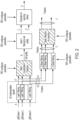
- FIG. 2 illustrates an example of a measurement model for a UE.
- the beams at step A in FIG. 2 can refer to SSB or channel state information reference signal (CSI-RS) resources.
- the UE may apply UE-implementation specific Layer 1 (L1) averaging (for example, with 5 samples) to the set of beams to reduce fluctuations in measurements caused by fast fading and measurement error.
- L1 Layer 1
- the accuracy of the L1 measurements may depend on the UE implementation; however, a certain minimum accuracy may be achieved by performance requirements.
- the UE can select any L1 sampling rate, filter realization, or L3 output rate so long as the minimum requirements are satisfied.
- the forgetting factor may be 2 ⁇ k L 3 4 , where k L 3 is the L3 filterCoefficient for the corresponding measurement quantity (e.g., RSRP or RSRQ), and defined in the MeasObjectNR which can be sent to the UE along with RRC reconfiguration message or the RRC resume message.
- the value of the L3 filterCoefficient may be between 0 and 19, as shown in FIG. 3 .
- the ⁇ value may be adapted such that the time characteristics of the filter can be preserved at different input rates, observing that the filterCoefficient assumes a sample rate equal to X ms.
- the value of X is equivalent to one intra-frequency L1 measurement period, which may assume non-DRX operation and/or depend on frequency range.
- the minimum measurement period to generate one L1 filtered sample in frequency range 1 (FR1) and frequency range 2 (FR2) may be 200 ms and 400 ms, respectively.
- the network may signal filterCoefficient k L 3 to the MPUE using an RRC Reconfiguration message.
- (1 - ⁇ ) may be the value that adjusts the impact of previous measurements (i.e., F n -1 ) on the new measurement (i.e., M n ) .
- L1 of the UE can be limited to measure at various sampling rate (i.e., T smp ) depending on number of panels, the switching schedule, and the switch delay.
- T smp sampling rate
- the UE may derive a new forgetting factor ⁇ ' for its sampling rate T smp based on the configured filter coefficient k L 3 (leading to forgetting factor ⁇ ) corresponding to a specified sample rate X.
- Tsmp 80 ms.
- MPUE Assumption 1 would need a higher alpha value to match the forgetting factor of a typical UE. For example, if ⁇ is 0.5, ⁇ ' would be 0.9625.
- RSRP reference signal received power
- RSRQ reference signal received quality
- FIG. 4 illustrates an example of different RR panel scan rates, with SSB burst periodicities of 20ms.
- the sampling rate of the measurements with MPUE Assumption-1 is shown as ⁇ 1/80 ms, 1/160 ms, 1/320 ms ⁇ for RR scan rates of ⁇ 1, 1/2, 1/4 ⁇ , respectively.
- the sampling rate may drop even further, depending on the MPUE panel scan rate. It is noted that the network has no control of the MPUE panel scan rate; therefore, L1 sampling rates and L3 input rates equal one measurement period A 1 .
- Inter-cell mobility procedures may include baseline handover (HO), conditional handover (CHO), and dual active protocol stack (DAPS).
- handover may be initiated by network-configured events. For example, in baseline HO, once an A3 event (or other configured Ax event) condition is fulfilled, the UE may send a measurement report, and the serving cell may prepare the target cell (e.g., one of the cells indicated in the measurement report). Event A3 may provide a handover preparation triggering mechanism based upon the measurement results at step C in FIG. 2 .
- Event A3 may be fulfilled if it fulfills the condition MN + CIOHO > MS + offHO, where MN is the measurement of the neighboring cell, MS is the measurement of the serving cell, offHO is an offset value (also called HO hysteresis or HO margin), and CIOHO is a cell individual offset.
- A3 event expires (and the UE sends a measurement report) if this condition is fulfilled for each measurement MN during a certain time to trigger TTTHO.
- FIGs. 5 and 6 illustrate examples of the measurement accuracy for FR1 and FR2 cases, respectively.
- the measurement accuracy may be interpreted based on the standard deviation after L3 filtering.
- L3 filter coefficient k L 3 may be set to 4; thus, the L3 filter time constant may be calculated as 200 ms for FIG. 1 (FR1) and 400 ms for FIG. 2 (FR2).
- each figure depicts 3 different cases: the top depicts 3 samples used in L1 filtering with a UE speed of 60km/h; the middle depicts 5 samples used in L1 filtering with a UE speed of 60km/h; and the bottom depicts 3 samples used in L1 filtering with a UE speed of 3km/h.
- L3 filtering output becomes more inaccurate (based on standard deviation) when L3 sampling period (input rate) increases, especially if the L3 sampling period is higher than the filter time constant. As long as the L3 sampling period is below a filter time constant, this effect is relatively small.
- L3 sampling periods Long L3 sampling periods are likely, especially for MPUE Assumption-1 as certain panels are not measured often enough due to panel activation restrictions.
- the network has no control on the MPUE panel activation and L3 sampling periods since they are UE implementation specific. This impacts the network since unreliable measurements can lead to ping-pongs, and even radio link failures (RLFs), which can increase the interruption time of the UEs.
- RLFs radio link failures
- the filter time constant is configured by the network at once, as shown in FIG. 3 , and not changed until the UE receives new configurations, e.g., RRC reconfiguration and corresponds to L1 measurement period X.
- Certain example embodiments described herein may provide various benefits and/or advantages to overcome the disadvantages described above. For example, certain example embodiments may ensure high measurement accuracy of L3 filtering, enabling reliable mobility decisions regardless of the MPUE panel activation algorithm. In this way, the network is unaware of the panel implementation details of the UE, including the activation status, and thus the input rate of the L3 filter. The measurement accuracy of L3 filtering remains under the control of the network. Thus, certain example embodiments discussed below are directed to improvements in computer-related technology.
- certain example embodiments may improve measurement accuracy for MPUEs with a single baseband unit (i.e., MPUE Assumption-1).
- the UE may modify the scaling of the filter coefficient such that filter time constant increases when an L3 sampling rate increases based on network configuration, especially when the L3 sampling rate is larger than the filter time constant T cst ; for example, as illustrated in FIG. 8 , X axis represents the L3 sampling rate of the UE, and Y axis represents the filter time constant.
- the network may provide a scaling factor (e.g., tan( ⁇ )) when the UE performs scaling (e.g., if the L3 sampling rate is higher than time constant derived from the configured filter coefficient).
- the configurations may be defined in the MeasObjectNR, which may be sent to the UE along with an RRC reconfiguration message.
- FIG. 7 illustrates an example of a signaling diagram, according to certain example embodiments.
- the example signalling diagram of FIG. 7 depicts how to improve measurement accuracy for multipanel UEs with a single baseband unit, according to certain example embodiments.
- UE 710 and NE 720 may be similar to UE 1210 and NE 1220, as illustrated in FIG. 12 , according to certain example embodiments.
- NE 720 may configure at least one L3 filter coefficient k L 3 .
- NE 720 may calculate the at least one L3 filter time constant T cst_x according to at least one of at least one L3 filter time constant T cst derived from the at least one L3 filter coefficient k L 3 , at least one input rate of L3 infinite impulse response filtering T smp , at least one sampling rate X , and at least one scaling factor.
- X comprises a sampling rate
- kL3 comprises a filter coefficient associated with L3 infinite impulse response filtering
- T smp comprises a sampling period of L3 infinite impulse response filtering
- ⁇ comprises a float
- tan( ⁇ ) comprises a scaling factor.
- the at least one filter coefficient kLa may include an L3 filterCoefficient and/or a value from 0 to 19. Additionally or alternatively, the scaling factor tan( ⁇ ) may be applied when sampling period Tsmp of a layer 3 infinite impulse response filtering is higher than Tcst or the sampling rate X.
- the at least one filter coefficient kL3 may comprise an L3 infinite impulse response.
- X > T cst when kLa ⁇ 4 and T smp > X.
- NE 720 can provide a table of filter time characteristics based on the different filter input rates, which may reduce the complexity of the scaling.
- NE 720 may indicate to UE 710 to scale down (reduce) time-to-trigger in case UE 710 applies scaling factors to the time characteristics of the filter. Increasing the filter time constant of the filter can introduce additional delay on measurements, and in order to reduce the overall handover delay, TTT may be shortened.
- NE 720 may transmit at least one of at least one L3 filter time constant T cst_x and the at least one scaling factor to UE 710.
- the at least one scaling factor may be transmitted in at least one radio resource control reconfiguration message and/or be configured to calculate Tcst_x.
- NE 720 may transmit at least one indication to reduce at least one time-to-trigger when UE 710 applies the at least one scaling factor to at least one time characteristic of the L3 infinite impulse response filtering.
- the at least one L3 filter time constant T cst_x may comprise a table.
- UE 710 may update at least one current filter time constant according to at least one of the received T cst_x and the at least one scaling factor As a result, the measurement accuracy may be improved by applying the scaling factor to update the at least one current filter time constant.
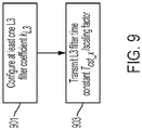
- FIG. 9 illustrates an example of a flow diagram of a method, according to certain example embodiments.
- the method illustrated in FIG. 9 may be performed by a NE, such as NE 1220 illustrated in FIG. 12 , according to various example embodiments.
- the NE may configure at least one L3 filter coefficient k L 3 .
- the NE may calculate the at least one L3 filter time constant T cst_x according to at least one of at least one L3 filter time constant T cst derived from the at least one L3 filter coefficient k L 3 , at least one input rate of L3 infinite impulse response filtering T smp , at least one sampling rate X , and at least one scaling factor.
- X comprises a sampling rate
- kL3 comprises a filter coefficient associated with L3 infinite impulse response filtering
- T smp comprises sampling period of L3 infinite impulse response filtering
- ⁇ comprises a float
- tan( ⁇ ) comprises a scaling factor.
- the at least one filter coefficient kLa may include an L3 filterCoefficient and/or a value from 0 to 19. Additionally or alternatively, the scaling factor tan( ⁇ ) may be applied when sampling period Tsmp of a layer 3 infinite impulse response filtering is higher than Tcst or the sampling rate X.
- the at least one filter coefficient kL3 may comprise an L3 infinite impulse response.
- X > T cst when kLa ⁇ 4 and T smp > X.
- the NE may transmit the at least one filter time constant T cst_x to at least one UE, which may be similar to UE 1210 illustrated in FIG. 12 .
- at least one scaling factor may also be transmitted in at least one radio resource control reconfiguration message and configured to calculate Tcst_x.
- the NE may transmit at least one indication to reduce at least one time-to-trigger when the UE applies the at least one scaling factor to at least one time characteristic of the L3 infinite impulse response filtering.
- the at least one L3 filter time constant T cst_x may comprise a table.
- the NE may provide a table of filter time characteristics based on the different filter input rates, which may reduce the complexity of the scaling.
- the NE may indicate to the UE to scale down (reduce) time-to-trigger in case the UE applies scaling factors to the time characteristics of the filter. Increasing the filter time constant of the filter can introduce additional delay on measurements, and in order to reduce the overall handover delay, TTT may be shortened.
- FIG. 10 illustrates an example of a flow diagram of another method, according to certain example embodiments.
- the example flow diagram of FIG. 10 may be performed by a UE, such as UE 1210 illustrated in FIG. 12 , according to various example embodiments.
- the UE may receive at least one of at least one L3 filter time constant T cst_x or at least one scaling factor from a NE, which may be similar to NE 1220 illustrated in FIG. 12 .
- the at least one L3 filter time constant T cst_x may be calculated according to at least one of at least one L3 filter time constant T cst derived from the at least one L3 filter coefficient k L 3 , at least one input rate of L3 infinite impulse response filtering T smp , at least one sampling rate X, and the at least one scaling factor.
- X comprises a sampling rate
- kL3 comprises a filter coefficient associated with L3 infinite impulse response filtering
- T smp comprises a sampling period of L3 infinite impulse response filtering
- ⁇ comprises a float
- tan( ⁇ ) comprises a scaling factor.
- the scaling factor tan( ⁇ ) may be applied when sampling period Tsmp of a layer 3 infinite impulse response filtering is higher than Tcst or the sampling rate X.
- the at least one filter coefficient kL3 may comprise an L3 infinite impulse response.
- the at least one scaling factor may be transmitted in at least one radio resource control reconfiguration message and configured to calculate Tcst_x.
- the at least one filter coefficient kLa may comprise an L3 filterCoefficient and/or a value from 0 to 19.
- X > T cst when kLa ⁇ 4 and T smp > X.
- the UE may update at least one current filter time constant according to at least one of the received T cst_x or the at least one scaling factor.
- FIG. 11 illustrates an example of testing results, according to certain example embodiments.
- the sampling rate i.e., X
- X is assumed to be 200ms for FR1, 400ms for FR2 with filterCoefficient equal to 4.
- the filter time constant i.e., T cst
- T cst the filter time constant
- the UE applies scaling in case the input rate of the filter (i.e., T smp ) is higher than the filter time constant.
- adaptive filter time characteristics provide better accuracy (i.e., lower STD if the input rate of the L3 filter the increases). Table 1 below shows that, even if the input rate of the filter increases (e.g., due to multi-panel UE design, panel activation algorithm, etc.), the measurement accuracy in the same level ( ⁇ 1.2 standard deviation) may be sustained.
- one step may be used for a UE to adjust the time characteristics of the filter before adapting the forgetting factor to increase the accuracy of the measurements.
- FIG. 12 illustrates an example of a system, according to certain example embodiments.
- a system may include multiple devices, such as, for example, UE 1210 and/or NE 1220.
- UE 1210 may include one or more of a mobile device, such as a mobile phone, smart phone, personal digital assistant (PDA), tablet, or portable media player, digital camera, pocket video camera, video game console, navigation unit, such as a global positioning system (GPS) device, desktop or laptop computer, single-location device, such as a sensor or smart meter, or any combination thereof.
- a mobile device such as a mobile phone, smart phone, personal digital assistant (PDA), tablet, or portable media player, digital camera, pocket video camera, video game console, navigation unit, such as a global positioning system (GPS) device, desktop or laptop computer, single-location device, such as a sensor or smart meter, or any combination thereof.
- GPS global positioning system
- NE 1220 may be one or more of a base station, such as an eNB or gNB, a serving gateway, a server, and/or any other access node or combination thereof. Furthermore, UE 1210 and/or NE 1220 may be one or more of a citizens broadband radio service device (CBSD).
- CBSD citizens broadband radio service device
- NE 1220 may further comprise at least one gNB-CU, which may be associated with at least one gNB-DU.
- the at least one gNB-CU and the at least one gNB-DU may be in communication via at least one F1 interface, at least one Xn-C interface, and/or at least one NG interface via a 5GC.
- UE 1210 and/or NE 1220 may include at least one processor, respectively indicated as 1211 and 1221.
- Processors 1211 and 1221 may be embodied by any computational or data processing device, such as a central processing unit (CPU), application specific integrated circuit (ASIC), or comparable device.
- the processors may be implemented as a single controller, or a plurality of controllers or processors.
- At least one memory may be provided in one or more of the devices, as indicated at 1212 and 1222.
- the memory may be fixed or removable.
- the memory may include computer program instructions or computer code contained therein.
- Memories 1212 and 1222 may independently be any suitable storage device, such as a non-transitory computer-readable medium.
- a hard disk drive (HDD), random access memory (RAM), flash memory, or other suitable memory may be used.
- the memories may be combined on a single integrated circuit as the processor, or may be separate from the one or more processors.
- the computer program instructions stored in the memory, and which may be processed by the processors may be any suitable form of computer program code, for example, a compiled or interpreted computer program written in any suitable programming language.
- Processors 1211 and 1221, memories 1212 and 1222, and any subset thereof, may be configured to provide means corresponding to the various blocks of FIGS. 7-10 .
- the devices may also include positioning hardware, such as GPS or micro electrical mechanical system (MEMS) hardware, which may be used to determine a location of the device.
- MEMS micro electrical mechanical system
- Other sensors are also permitted, and may be configured to determine location, elevation, velocity, orientation, and so forth, such as barometers, compasses, and the like.
- transceivers 1213 and 1223 may be provided, and one or more devices may also include at least one antenna, respectively illustrated as 1214 and 1224.
- the device may have many antennas, such as an array of antennas configured for multiple input multiple output (MIMO) communications, or multiple antennas for multiple RATs. Other configurations of these devices, for example, may be provided.
- Transceivers 1213 and 1223 may be a transmitter, a receiver, both a transmitter and a receiver, or a unit or device that may be configured both for transmission and reception.
- the memory and the computer program instructions may be configured, with the processor for the particular device, to cause a hardware apparatus, such as UE, to perform any of the processes described above (i.e., FIGS. 7-10 ). Therefore, in certain example embodiments, a non-transitory computer-readable medium may be encoded with computer instructions that, when executed in hardware, perform a process such as one of the processes described herein. Alternatively, certain example embodiments may be performed entirely in hardware.
- an apparatus may include circuitry configured to perform any of the processes or functions illustrated in FIGS. 7-10 .
- circuitry may be hardware-only circuit implementations, such as analog and/or digital circuitry.
- circuitry may be a combination of hardware circuits and software, such as a combination of analog and/or digital hardware circuitry with software or firmware, and/or any portions of hardware processors with software (including digital signal processors), software, and at least one memory that work together to cause an apparatus to perform various processes or functions.
- circuitry may be hardware circuitry and or processors, such as a microprocessor or a portion of a microprocessor, that includes software, such as firmware, for operation. Software in circuitry may not be present when it is not needed for the operation of the hardware.
- apparatus 1210 may be controlled by memory 1212 and processor 1211 to configure at least one L3 filter coefficient k L 3 .
- Apparatus 1210 may also be controlled by memory 1212 and processor 1211 to transmit at least one of at least one L3 filter time constant T cst_x or at least one scaling factor to at least one user equipment.
- apparatus 1220 may be controlled by memory 1222 and processor 1221 to receive at least one of at least one L3 filter time constant T cst_x or at least one scaling factor. Apparatus 1220 may be further controlled by memory 1222 and processor 1221 to update at least one current filter time constant according to at least one of the received T cst_x or the at least one scaling factor.
- an apparatus may include means for performing a method, a process, or any of the variants discussed herein.
- the means may include one or more processors, memory, controllers, transmitters, receivers, and/or computer program code for causing the performance of the operation.
- Certain example embodiments may be directed to an apparatus that includes means for configuring at least one L3 filter coefficient k L 3 .
- the apparatus may further include means for transmitting at least one of at least one L3 filter time constant T cst_x or at least one scaling factor to at least one user equipment.
- Other example embodiments may be directed to an apparatus that includes means for receiving at least one of at least one L3 filter time constant T cst_x or at least one scaling factor.
- the apparatus may further include means for updating at least one current filter time constant according to at least one of the received T cst_x or the at least one scaling factor.
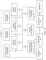
- FIG. 13 illustrates an example of a 5G network and system architecture, according to certain example embodiments. Shown are multiple network functions that may be implemented as software operating as part of a network device or dedicated hardware, as a network device itself or dedicated hardware, or as a virtual function operating as a network device or dedicated hardware.
- the NE and UE illustrated in FIG. 12 may be similar to UE 1210 and NE 1220, respectively.
- the user plane function (UPF) may provide services such as intra-RAT and inter-RAT mobility, routing and forwarding of data packets, inspection of packets, user plane quality of service (QoS) processing, buffering of downlink packets, and/or triggering of downlink data notifications.
- the application function (AF) may primarily interface with the core network to facilitate application usage of traffic routing and interact with the policy framework.
Landscapes
- Engineering & Computer Science (AREA)
- Computer Networks & Wireless Communication (AREA)
- Signal Processing (AREA)
- Physics & Mathematics (AREA)
- Mathematical Physics (AREA)
- Mobile Radio Communication Systems (AREA)
- Electromagnetism (AREA)
Applications Claiming Priority (1)
| Application Number | Priority Date | Filing Date | Title |
|---|---|---|---|
| US17/395,062 US11569888B1 (en) | 2021-08-05 | 2021-08-05 | Enhanced multi-panel user equipment measurement for improved mobility robustness |
Publications (1)
| Publication Number | Publication Date |
|---|---|
| EP4132076A1 true EP4132076A1 (de) | 2023-02-08 |
Family
ID=82786288
Family Applications (1)
| Application Number | Title | Priority Date | Filing Date |
|---|---|---|---|
| EP22188241.8A Pending EP4132076A1 (de) | 2021-08-05 | 2022-08-02 | Verbesserte layer-3-filterung in mehrfach-panel-benutzervorrichtungen für verbesserte messgenauigkeit |
Country Status (3)
| Country | Link |
|---|---|
| US (1) | US11569888B1 (de) |
| EP (1) | EP4132076A1 (de) |
| CN (1) | CN115707024A (de) |
Cited By (1)
| Publication number | Priority date | Publication date | Assignee | Title |
|---|---|---|---|---|
| JP7815384B1 (ja) * | 2024-10-16 | 2026-02-17 | ソフトバンク株式会社 | 情報処理装置、情報処理方法、およびプログラム |
Citations (1)
| Publication number | Priority date | Publication date | Assignee | Title |
|---|---|---|---|---|
| US20200033849A1 (en) * | 2017-05-05 | 2020-01-30 | Intel IP Corporation | Methods and arrangements to signal for aerial vehicles |
Family Cites Families (10)
| Publication number | Priority date | Publication date | Assignee | Title |
|---|---|---|---|---|
| US8442513B2 (en) * | 2008-11-04 | 2013-05-14 | Motorola Mobility Llc | Measurement report reliability in wireless communication systems |
| EP2608428B1 (de) * | 2011-12-22 | 2016-12-28 | ST-Ericsson SA | Adaptiver Filter zur Verwendung in der Funkressourcenverwaltung |
| GB2499080B (en) * | 2012-12-04 | 2014-12-31 | Broadcom Corp | Method and apparatus for adjusting layer 3 filter coefficients |
| WO2014201638A1 (zh) * | 2013-06-19 | 2014-12-24 | 华为技术有限公司 | 一种通信质量测量的方法和装置 |
| US11223403B2 (en) * | 2016-05-05 | 2022-01-11 | Nokia Technologies Oy | Mobility measurements |
| RU2742603C1 (ru) * | 2017-09-11 | 2021-02-09 | Телефонактиеболагет Лм Эрикссон (Пабл) | Улучшенные конфигурации фильтрации измерений для администрирования линии радиосвязи и администрирования радиоресурсов |
| US10856303B2 (en) * | 2017-10-06 | 2020-12-01 | Lg Electronics Inc. | Method for performing measurement and device supporting the same |
| US10404335B2 (en) * | 2017-10-20 | 2019-09-03 | Intel IP Corporation | Filter coefficient configuration in new radio systems |
| WO2019138288A1 (en) * | 2018-01-10 | 2019-07-18 | Nokia Technologies Oy | Beam consolidation and selection based on external information |
| US11516690B2 (en) * | 2020-02-12 | 2022-11-29 | Samsung Electronics Co., Ltd. | Sidelink measurements in V2X communication |
-
2021
- 2021-08-05 US US17/395,062 patent/US11569888B1/en active Active
-
2022
- 2022-08-02 EP EP22188241.8A patent/EP4132076A1/de active Pending
- 2022-08-04 CN CN202210931297.8A patent/CN115707024A/zh active Pending
Patent Citations (1)
| Publication number | Priority date | Publication date | Assignee | Title |
|---|---|---|---|---|
| US20200033849A1 (en) * | 2017-05-05 | 2020-01-30 | Intel IP Corporation | Methods and arrangements to signal for aerial vehicles |
Non-Patent Citations (4)
| Title |
|---|
| NOKIA ET AL: "3GPP TSG-RAN WG2 Meeting #103bis; R2-1814463; Potential Improvements of Mobility Robustness in LTE", vol. RAN WG2, no. Chengdu, China; 20181008 - 20181012, 28 September 2018 (2018-09-28), XP051523890, Retrieved from the Internet <URL:http://www.3gpp.org/ftp/tsg%5Fran/WG2%5FRL2/TSGR2%5F103bis/Docs/R2%2D1814463%2Ezip> [retrieved on 20180928] * |
| RENESAS MOBILE EUROPE LTD: "3GPP TSG-RAN WG4 Meeting #66bis; R4-131640; On L3 filtering for common E-RGCH monitoring", vol. RAN WG4, no. Chicago; 20130415 - 20130419, 4 April 2013 (2013-04-04), XP050701295, Retrieved from the Internet <URL:http://www.3gpp.org/ftp/tsg_ran/WG4_Radio/TSGR4_66bis/Docs/> [retrieved on 20130404] * |
| SAMSUNG: "3GPP TSG-RAN WG2 Meeting #83bis; R2-133589; Gradient based scaling, further information", vol. RAN WG2, no. Ljubljana, Slovenia; 20131007 - 20131011, 1 October 2013 (2013-10-01), XP050719303, Retrieved from the Internet <URL:http://www.3gpp.org/ftp/tsg_ran/WG2_RL2/TSGR2_83bis/Docs/> [retrieved on 20131001] * |
| SAMSUNG: "3GPP TSG-RAN WG4 Meeting #51bis; R4-092240; Considerations on L3 filter scaling when DRX is used", 3GPP DRAFT; R4-092240, 3RD GENERATION PARTNERSHIP PROJECT (3GPP), MOBILE COMPETENCE CENTRE ; 650, ROUTE DES LUCIOLES ; F-06921 SOPHIA-ANTIPOLIS CEDEX ; FRANCE, no. Los Angeles, CA; 20090625, 25 June 2009 (2009-06-25), XP050353489 * |
Cited By (1)
| Publication number | Priority date | Publication date | Assignee | Title |
|---|---|---|---|---|
| JP7815384B1 (ja) * | 2024-10-16 | 2026-02-17 | ソフトバンク株式会社 | 情報処理装置、情報処理方法、およびプログラム |
Also Published As
| Publication number | Publication date |
|---|---|
| US20230037650A1 (en) | 2023-02-09 |
| CN115707024A (zh) | 2023-02-17 |
| US11569888B1 (en) | 2023-01-31 |
Similar Documents
| Publication | Publication Date | Title |
|---|---|---|
| JP7693710B2 (ja) | 通信装置および通信方法 | |
| EP3503620B1 (de) | Verfahren, vorrichtung und system zur zellübergabe | |
| US10924915B2 (en) | Exchange of mobility information in cellular radio communications | |
| US10149219B2 (en) | User terminal, cellular base station, and processor | |
| US20190373442A1 (en) | Method for reporting mobility history of terminal and apparatus for supporting same | |
| US11678288B2 (en) | Synchronization of time sensitive communication hold-and-forward buffers with time sensitive communication assistance information | |
| US11924696B2 (en) | Reducing traffic interruption during handover | |
| US12308941B2 (en) | Neighbor low earth orbit/high altitude platform stations inter-satellite link change and synchronization signal block measurements | |
| EP3951418B1 (de) | Koordination der auswahl der sendeempfangspunkte, trps, zwischen basisstation und standortverwaltungsfunktion, lmf | |
| US20240147337A1 (en) | Method and apparatus for triggering of flight path reporting in a wireless communication system | |
| CN118633315A (zh) | 通信系统中的测量 | |
| US12556983B2 (en) | UE fallback from dual-active protocol stack to conditional handover | |
| EP4548496A1 (de) | Verfahren, kommunikationsvorrichtungen und nicht terrestrische infrastrukturausrüstung | |
| EP4132076A1 (de) | Verbesserte layer-3-filterung in mehrfach-panel-benutzervorrichtungen für verbesserte messgenauigkeit | |
| WO2024033109A1 (en) | Reception mode adaptation for multi receiver chain capable devices | |
| CN118215087A (zh) | 无线通信系统中的网络节点和用于网络节点的方法 | |
| US20240365294A1 (en) | Method for distribution unit components cooperation in terms of significant reduction of downlink user throughput | |
| US20240147339A1 (en) | Use of estimated arrival probability-related information to select target secondary nodes for early data forwarding for dual connectivity wireless communications | |
| WO2026073638A1 (en) | Communication regarding scg information for ltm cell change for ue | |
| WO2026032688A1 (en) | Candidate cell beam measurement | |
| WO2025210441A1 (en) | User equipment event-driven beam reports for group based beam reporting | |
| WO2025210452A1 (en) | User equipment event-driven beam reports for group based beam reporting |
Legal Events
| Date | Code | Title | Description |
|---|---|---|---|
| PUAI | Public reference made under article 153(3) epc to a published international application that has entered the european phase |
Free format text: ORIGINAL CODE: 0009012 |
|
| STAA | Information on the status of an ep patent application or granted ep patent |
Free format text: STATUS: THE APPLICATION HAS BEEN PUBLISHED |
|
| AK | Designated contracting states |
Kind code of ref document: A1 Designated state(s): AL AT BE BG CH CY CZ DE DK EE ES FI FR GB GR HR HU IE IS IT LI LT LU LV MC MK MT NL NO PL PT RO RS SE SI SK SM TR |
|
| STAA | Information on the status of an ep patent application or granted ep patent |
Free format text: STATUS: REQUEST FOR EXAMINATION WAS MADE |
|
| 17P | Request for examination filed |
Effective date: 20230724 |
|
| RBV | Designated contracting states (corrected) |
Designated state(s): AL AT BE BG CH CY CZ DE DK EE ES FI FR GB GR HR HU IE IS IT LI LT LU LV MC MK MT NL NO PL PT RO RS SE SI SK SM TR |
|
| STAA | Information on the status of an ep patent application or granted ep patent |
Free format text: STATUS: EXAMINATION IS IN PROGRESS |
|
| 17Q | First examination report despatched |
Effective date: 20240514 |