EP4132082A1 - Verfahren und vorrichtung zum senden und empfangen von signalen in einem drahtloskommunikationssystem - Google Patents
Verfahren und vorrichtung zum senden und empfangen von signalen in einem drahtloskommunikationssystem Download PDFInfo
- Publication number
- EP4132082A1 EP4132082A1 EP21792820.9A EP21792820A EP4132082A1 EP 4132082 A1 EP4132082 A1 EP 4132082A1 EP 21792820 A EP21792820 A EP 21792820A EP 4132082 A1 EP4132082 A1 EP 4132082A1
- Authority
- EP
- European Patent Office
- Prior art keywords
- ssb
- smtc3
- list
- measurement
- information
- Prior art date
- Legal status (The legal status is an assumption and is not a legal conclusion. Google has not performed a legal analysis and makes no representation as to the accuracy of the status listed.)
- Granted
Links
Images


Classifications
-
- H—ELECTRICITY
- H04—ELECTRIC COMMUNICATION TECHNIQUE
- H04L—TRANSMISSION OF DIGITAL INFORMATION, e.g. TELEGRAPHIC COMMUNICATION
- H04L5/00—Arrangements affording multiple use of the transmission path
- H04L5/003—Arrangements for allocating sub-channels of the transmission path
- H04L5/0048—Allocation of pilot signals, i.e. of signals known to the receiver
- H04L5/005—Allocation of pilot signals, i.e. of signals known to the receiver of common pilots, i.e. pilots destined for multiple users or terminals
-
- H—ELECTRICITY
- H04—ELECTRIC COMMUNICATION TECHNIQUE
- H04W—WIRELESS COMMUNICATION NETWORKS
- H04W24/00—Supervisory, monitoring or testing arrangements
- H04W24/10—Scheduling measurement reports ; Arrangements for measurement reports
-
- H—ELECTRICITY
- H04—ELECTRIC COMMUNICATION TECHNIQUE
- H04L—TRANSMISSION OF DIGITAL INFORMATION, e.g. TELEGRAPHIC COMMUNICATION
- H04L5/00—Arrangements affording multiple use of the transmission path
- H04L5/0091—Signalling for the administration of the divided path, e.g. signalling of configuration information
- H04L5/0094—Indication of how sub-channels of the path are allocated
-
- H—ELECTRICITY
- H04—ELECTRIC COMMUNICATION TECHNIQUE
- H04W—WIRELESS COMMUNICATION NETWORKS
- H04W24/00—Supervisory, monitoring or testing arrangements
- H04W24/08—Testing, supervising or monitoring using real traffic
-
- H—ELECTRICITY
- H04—ELECTRIC COMMUNICATION TECHNIQUE
- H04W—WIRELESS COMMUNICATION NETWORKS
- H04W48/00—Access restriction; Network selection; Access point selection
- H04W48/16—Discovering, processing access restriction or access information
-
- H—ELECTRICITY
- H04—ELECTRIC COMMUNICATION TECHNIQUE
- H04W—WIRELESS COMMUNICATION NETWORKS
- H04W56/00—Synchronisation arrangements
- H04W56/001—Synchronization between nodes
-
- H—ELECTRICITY
- H04—ELECTRIC COMMUNICATION TECHNIQUE
- H04W—WIRELESS COMMUNICATION NETWORKS
- H04W84/00—Network topologies
- H04W84/02—Hierarchically pre-organised networks, e.g. paging networks, cellular networks, WLAN [Wireless Local Area Network] or WLL [Wireless Local Loop]
- H04W84/04—Large scale networks; Deep hierarchical networks
- H04W84/042—Public Land Mobile systems, e.g. cellular systems
- H04W84/047—Public Land Mobile systems, e.g. cellular systems using dedicated repeater stations
Definitions
- the present disclosure relates to a method and apparatus for transmitting and receiving signals in a wireless communication system, and more particularly, to a method and apparatus for providing configuration information for a synchronization signal measurement time in an integrated access and backhaul (IAB) system.
- IAB integrated access and backhaul
- 5th generation (5G) communication systems are being predicted to be connected to communication networks.
- Examples of the things connected to networks may include vehicles, robots, drones, home appliances, displays, smart sensors installed in various infrastructures, construction machines, and factory apparatuses.
- Mobile devices are expected to evolve into various form factors such as augmented reality glasses, virtual reality headsets, and hologram devices.
- 6G communication systems are being called systems beyond 5G communication (beyond 5G).
- the maximum transmission rate is tera (i.e., 1,000 giga) bps and the radio latency is 100 microseconds ( ⁇ sec). That is, compared to the 5G communication systems, in the 6G communication systems, the transmission rate increases by 50 times and the radio latency decreases to 1/10 (one tenth).
- the 6G communication systems are considering implementation in the terahertz band (e.g., the 95 gigahertz (95 GHz) to 3 terahertz (3 THz) band).
- the terahertz band e.g., the 95 gigahertz (95 GHz) to 3 terahertz (3 THz) band.
- mmWave millimeter wave
- the terahertz bands the importance of technologies capable of ensuring the signal reach, that is, the coverage, is expected to increase due to more severe path loss and atmospheric absorption.
- Multiple antenna transmission technologies such as new waveforms, beamforming and massive multiple-input and multiple-output (massive MIMO), full dimensional MIMO (FD-MIMO), array antennas, and large scale antennas, which are superior to radio frequency (RF) devices, antennas, and orthogonal frequency division multiplexing (OFDM) in terms of the coverage, should be developed as main technologies for ensuring the coverage.
- new technologies such as metamaterial-based lenses and antennas, high-dimensional spatial multiplexing technologies using orbital angular momentum (OAM), and reconfigurable intelligent surface (RIS) are being discussed to improve the coverage of terahertz band signals.
- OFAM orbital angular momentum
- RIS reconfigurable intelligent surface
- full duplex technologies in which the uplink and the downlink simultaneously use the same frequency resource at the same time, network technologies integratedly using satellites and high-altitude platform stations (HAPS) or the like, network architecture innovation technologies supporting mobile base stations or the like and enabling network operation optimization and automation or the like, dynamic spectrum sharing technologies through collision avoidance based on spectrum usage prediction, Al-based communication technologies realizing system optimization by using artificial intelligence (Al) from the design stage and internalizing an end-to-end AI support function, and next-generation distributed computing technologies realizing services of complexity exceeding the limit of terminal operation capacity by using ultra-high-performance communication and computing resources (e.g., mobile edge computing (MEC) and cloud) are being developed.
- HAPS high-altitude platform stations
- MEC mobile edge computing
- the 6G communication systems Due to the research and development of the 6G communication systems, the next hyper-connected experience is expected to be possible through the hyper-connectivity of the 6G communication systems including not only the connection between things but also the connection between humans and things.
- the 6G communication systems are predicted to provide services such as truly immersive extended reality (truly immersive XR), high-fidelity mobile hologram, and digital replica.
- services such as remote surgery, industrial automation, and emergency response through security and reliability enhancement will be applied in various fields such as industry, medical care, vehicles, and home appliances by being provided through the 6G communication systems.
- Described embodiments provide an apparatus and method capable of effectively providing a service in a wireless communication system.
- a method performed by an integrated access and backhaul-mobile termination (IAB-MT) in a wireless communication system includes receiving configuration information for synchronization signal block (SSB) measurement, obtaining an SSB Measurement Time Configurations (SMTC3) list from the received configuration information, identifying cells and SSB measurement timing based on parameters included in the obtained SMTC3 list, and performing measurement of an SSB corresponding to an ssbToMeasure parameter included in the obtained SMTC3 list, for the identified cells, based on the SSB measurement timing.
- SSB synchronization signal block
- SMTC3 Measurement Time Configurations
- Described embodiments provide a signal transmitting/receiving method capable of effectively providing a service in a wireless communication system by providing synchronization signal configuration information.
- a terminal When a terminal measures a reference signal to recognize a neighbor node, it may receive measurement information for a general terminal and measurement information for a mobile termination (MT) in one measurement object and measure each reference signal of a general cell and an integrated access and backhaul (IAB) neighbor node to report necessary cell information for the terminal to a base station.
- MT mobile termination
- IAB integrated access and backhaul
- the present disclosure relates to a method by which a mobile termination (MT) detects neighbor nodes in an integrated access and backhaul (IAB) system.
- a mobile termination detects neighbor nodes in an integrated access and backhaul (IAB) system.
- IAB integrated access and backhaul
- a reference signal configured by a donor base station
- a reference signal configured by a base station for a general terminal and a reference signal additionally configured for neighbor nodes are simultaneously signaled
- an MT having received the same may measure a signal for detecting a neighbor node by using two pieces of information.
- a reference signal having multiple-frequency or singlefrequency information may be configured for an MT having different types of capabilities, and depending on the capability, the MT may measure a signal received through multiple frequencies or may measure a signal received through a single frequency.
- a terminal may receive measurement configuration information from a serving cell, identify whether a measurement object (MO) configured in the terminal is an MO corresponding to a synchronization signal block (SSB) to be measured, based on the measurement configuration information, receive at least one SSB measurement time configuration (SMTC) information among SMTC1 information and SMTC3 information, based on a measurement frequency identified through the measurement configuration information and an SSB index configured through subcarrier spacing, when the MO corresponding to the SSB to be measured is configured in the terminal, and perform SSB measurement based on the received SMTC information.
- MO measurement object
- SSB synchronization signal block
- a method performed by an integrated access and backhaul-mobile termination (IAB-MT) in a wireless communication system includes receiving configuration information for synchronization signal block (SSB) measurement, obtaining an SSB Measurement Time Configurations (SMTC3) list from the received configuration information, identifying cells and SSB measurement timing based on parameters included in the obtained SMTC3 list, and performing measurement of an SSB corresponding to an ssbToMeasure parameter included in the obtained SMTC3 list, for the identified cells, based on the SSB measurement timing.
- SSB synchronization signal block
- SMTC3 Measurement Time Configurations
- a method performed by a base station in a wireless communication system includes transmitting configuration information for synchronization signal block (SSB) measurement, and transmitting at least one SSB, wherein the configuration information for the SSB measurement includes an SSB measurement time configuration 3 (SMTC3) list, cells and SSB measurement timing are identified based on parameters included in the SMTC3 list, and measurement of an SSB corresponding to an ssbToMeasure parameter included in the SMTC3 list is performed by an integrated access and backhaul-mobile termination (IAB-MT) for the identified cells based on the SSB measurement timing.
- SSB synchronization signal block
- an integrated access and backhaul-mobile termination (IAB-MT) in a wireless communication system includes a transceiver, and a processor configured to receive configuration information for synchronization signal block (SSB) measurement through the transceiver, obtain an SSB measurement time configuration 3 (SMTC3) list from the received configuration information, identify cells and SSB measurement timing based on parameters included in the obtained SMTC3 list, and perform measurement of an SSB corresponding to an ssbToMeasure parameter included in the obtained SMTC3 list, for the identified cells, based on the SSB measurement timing.
- SSB synchronization signal block
- SMTC3 SSB measurement time configuration 3
- a base station in a wireless communication system includes a transceiver, and a processor configured to transmit configuration information for synchronization signal block (SSB) measurement through the transceiver, and transmit at least one SSB through the transceiver, wherein the configuration information for the SSB measurement includes an SSB Measurement time configuration 3 (SMTC3) list, cells and SSB measurement timing are identified based on parameters included in the SMTC3 list, and measurement of an SSB corresponding to an ssbToMeasure parameter included in the SMTC3 list is performed by an integrated access and backhaul-mobile termination (IAB-MT) for the identified cells based on the SSB measurement timing.
- SSB synchronization signal block
- each block of process flowchart diagrams and combinations of flowchart diagrams may be performed by computer program instructions. Because these computer program instructions may be mounted on a processor of a general-purpose computer, special-purpose computer, or other programmable data processing equipment, the instructions executed through a processor of a computer or other programmable data processing equipment may generate a means of performing the functions described in the flowchart block(s). Because these computer program instructions may be stored in a computer-executable or computer-readable memory that may be directed to a computer or other programmable data processing equipment to implement a function in a particular manner, the instructions stored in the computer-executable or computer-readable memory may also produce a production item containing an instruction means of performing the functions described in the flowchart block(s).
- the computer program instructions may also be mounted on a computer or other programmable data processing equipment, the instructions performing a series of operations on the computer or other programmable data processing equipment to generate a computer-implemented process to perform the computer or other programmable data processing equipment may also provide operations for executing the functions described in the flowchart block(s).
- each block may represent a portion of a module, segment, or code including one or more executable instructions for executing one or more specified logical functions.
- the functions mentioned in the blocks may also occur in a different order in some alternative implementation examples. For example, two blocks illustrated in succession may actually be performed substantially at the same time or may sometimes be performed in the opposite order depending on the corresponding function.
- the term "unit” used in the present embodiments may refer to a software component or a hardware component such as a field programmable gate array (FPGA) or an application specific integrated circuit (ASIC) and the “unit” may perform certain functions.
- the “unit” is not limited to software or hardware.
- the “unit” may be configured to be in an addressable storage medium or may be configured to operate one or more processors.
- the "unit” may include components such as software components, object-oriented software components, class components, and task components and may include processes, functions, attributes, procedures, subroutines, segments of program code, drivers, firmware, microcode, circuits, data, databases, data structures, tables, arrays, and variables.
- a function provided by the components and “units” may be associated with the smaller number of components and “units” or may be further divided into additional components and “units”.
- the components and “units” may be implemented to operate one or more central processing units (CPUs) in a device or a security multimedia card.
- the "unit” may include one or more processors.
- 3GPP LTE 3rd Generation Partnership Project Long Term Evolution
- FIG. 1 is a diagram illustrating a structure of an LTE system.
- a radio access network of the LTE system may include next-generation base stations (e.g., evolved Node Bs (eNBs), Node Bs, or base stations) 1-05, 1-10, 1-15, and 1-20, a mobility management entity (MME) 1-25, and a serving-gateway (S-GW) 1-30.
- eNBs evolved Node Bs
- MME mobility management entity
- S-GW serving-gateway
- a user terminal e.g., a user equipment (UE) or a terminal
- UE user equipment
- S-GW serving-gateway
- the eNBs 1-05 to 1-20 may correspond to the existing Node Bs of the UMTS system.
- the eNB may be connected to the UE 1-35 through a radio channel and may perform a more complex function than the existing Node B.
- all user traffic including real-time services such as Voice over IP (VoIP) through the Internet protocol may be serviced on a shared channel.
- VoIP Voice over IP
- a device for collecting and scheduling state information such as the buffer states of UEs, available transmission power states, and channel states may be required, which may be performed by the eNBs 1-05 to 1-20.
- One eNB may generally control a plurality of cells.
- the LTE system may use Orthogonal Frequency Division Multiplexing (OFDM) as a radio access technology in a 20 MHz bandwidth.
- OFDM Orthogonal Frequency Division Multiplexing
- AMC adaptive modulation & coding
- the S-GW 1-30 may be a device for providing a data bearer and may add or release a data bearer based on the control by the MME 1-25.
- the MME 1-25 may be an entity for performing various control functions as well as a mobility management function for a terminal and may be connected to a plurality of base stations.
- FIG. 2 is a diagram illustrating a radio protocol architecture of an LTE system.
- the radio protocol of the LTE system may include Packet Data Convergence Protocol (PDCP) 2-05 and 2-40, Radio Link Control (RLC) 2-10 and 2-35, and Medium Access Control (MAC) 2-15 and 2-30 in each of a terminal and an eNB.
- PDCP Packet Data Convergence Protocol
- RLC Radio Link Control
- MAC Medium Access Control
- the PDCP may perform operations such as IP header compression/decompression.
- IP header compression/decompression The main functions of the PDCP may be summarized as follows.
- the RLC 2-10 and 2-35 may reconfigure a PDCP packet data unit (PDU) in a suitable size to perform an ARQ operation or the like.
- PDU packet data unit
- the MAC 2-15 and 2-30 may be connected to several RLC entities configured in one terminal and may perform an operation of multiplexing RLC PDUs into MAC PDUs and demultiplexing RLC PDUs from MAC PDUs.
- the main functions of the MAC 2-15 and 2-30 may be summarized as follows.
- Physical layers 2-20 and 2-25 may channel-code and modulate upper layer data, generate OFDM symbols, and transmit the same through radio channels or may demodulate and channel-decode OFDM symbols received through radio channels and transmit the result thereof to the upper layer.
- FIG. 3 is a diagram illustrating a structure of a next-generation mobile communication system.
- a radio access network of the next-generation mobile communication system may include a next-generation base station (new radio Node B) (hereinafter NR gNB or NR base station) 3-10 and a next-generation radio core network (new radio core network (NR CN)) 3-05.
- NR gNB next-generation base station
- NR CN next-generation radio core network
- a next-generation radio user terminal (new radio user equipment (NR UE) or terminal) 3-15 may access an external network through the NR gNB 3-10 and the NR CN 3-05.
- the NR gNB 3-10 may correspond to an evolved Node B (eNB) of the existing LTE system.
- the NR gNB may be connected to the NR UE 3-15 through a radio channel and may provide a better service than the existing Node B.
- all user traffic may be serviced on a shared channel.
- a device for collecting and scheduling state information such as the buffer states of UEs, available transmission power states, and channel states may be required, which may be performed by the NR NB 3-10.
- One NR gNB may generally control a plurality of cells.
- a bandwidth larger than or equal to the current maximum bandwidth may be applied to implement ultra-high-speed data transmission compared to the current LTE.
- a beamforming technology may be additionally combined by using Orthogonal Frequency Division Multiplexing (OFDM) as a radio access technology.
- OFDM Orthogonal Frequency Division Multiplexing
- AMC adaptive modulation & coding
- the NR CN 3-05 may perform functions such as mobility support, bearer configuration, and Quality of Service (QoS) configuration.
- the NR CN may be an apparatus for performing various control functions as well as a mobility management function for a terminal and may be connected to a plurality of base stations.
- the next-generation mobile communication system may also be linked with the existing LTE system, and the NR CN may be connected to an MME 3-25 through a network interface.
- the MME may be connected to an eNB 3-30 that is an existing base station.
- FIG. 4 is a diagram illustrating a radio protocol architecture of a next-generation mobile communication system to which the present disclosure may be applied.
- the radio protocol of the next-generation mobile communication system may include NR Service Data Adaptation Protocol (SDAP) 4-01 and 4-45, NR PDCP 4-05 and 4-40, NR RLC 4-10 and 4-35, and NR MAC 4-15 and 4-30 in each of a terminal and an NR base station.
- SDAP NR Service Data Adaptation Protocol
- NR PDCP 4-05 and 4-40 NR RLC 4-10 and 4-35
- NR MAC 4-15 and 4-30 in each of a terminal and an NR base station.
- the main functions of the NR SDAP 4-01 and 4-45 may include some of the following functions.
- the terminal may be configured with a Radio Resource Control (RRC) message for each PDCP entity, for each bearer, or for each logical channel whether to use a header of the SDAP entity or whether to use a function of the SDAP entity.
- RRC Radio Resource Control
- a 1-bit non-access stratum (NAS) Quality of Service (QoS) reflection configuration indicator (NAS reflective QoS) and a 1-bit access stratum (AS) QoS reflection configuration indicator (AS reflective QoS) of the SDAP header may indicate the terminal to update or reconfigure mapping information between a QoS flow and a data bearer for the uplink and the downlink.
- the SDAP header may include QoS flow ID information representing the QoS.
- the QoS information may be used as data processing priority and scheduling information or the like to support a smooth service.
- the main functions of the NR PDCP 4-05 and 4-40 may include at least some of the following functions.
- the reordering function of the NR PDCP entity may mean a function of reordering the PDCP PDUs received from the lower layer in order based on a PDCP sequence number (SN).
- the reordering function of the NR PDCP entity may include a function of transmitting data to the upper layer in the reordered order and may include at least one of a function of directly transmitting data without considering the order, a function of rearranging the order and recording the missing PDCP PDUs, a function of reporting the state of the missing PDCP PDUs to the transmitting side, or a function of requesting retransmission of the missing PDCP PDUs.
- the main functions of the NR RLC 4-10 and 4-35 may include at least some of the following functions.
- the sequential transmission (in-sequence delivery) function of the NR RLC entity may mean a function of sequentially transmitting the RLC SDUs received from the lower layer to the upper layer.
- the sequential transmission (in-sequence delivery) function of the NR RLC entity may include a function of reassembling and then transmitting the same.
- the sequential transmission (in-sequence delivery) function of the NR RLC entity may include a function of rearranging the received RLC PDUs based on the RLC sequence number (SN) or the sequence number (SN), may include a function of rearranging the order and recording the missing RLC PDUs, may include a function of reporting the state of the missing RLC PDUs to the transmitting side, and may include a function of requesting retransmission of the missing RLC PDUs.
- the sequential transmission (in-sequence delivery) function of the NR RLC entity may include a function of sequentially transmitting, when there is a missing RLC SDU, only the RLC SDUs up to before the missing RLC SDU to the upper layer.
- the sequential transmission (in-sequence delivery) function of the NR RLC entity may include a function of sequentially transmitting all RLC SDUs received before the start of a timer to the upper layer, when a certain timer has expired even when there is a missing RLC SDU.
- the sequential transmission (in-sequence delivery) function of the NR RLC entity may include a function of sequentially transmitting all RLC SDUs received up to now to the upper layer, when a certain timer has expired even when there is a missing RLC SDU.
- the NR RLC entity may process the RLC PDUs in the order of reception regardless of the sequence number (out-of-sequence delivery) and transmit the same to the NR PDCP entity.
- the NR RLC entity may receive segments stored in a buffer or to be received, reconfigure the segments into a single RLC PDU, and then transmit the same to the NR PDCP entity.
- the NR RLC layer may not include the concatenation function, and this function may be performed in the NR MAC layer or may be replaced with the multiplexing function of the NR MAC layer.
- the non-sequential transmission (out-of-sequence delivery) function of the NR RLC entity may mean a function of directly transmitting the RLC SDUs received from the lower layer to the upper layer regardless of the order thereof.
- the non-sequential transmission (out-of-sequence delivery) function of the NR RLC entity may include a function of reassembling and then transmitting the same.
- the non-sequential transmission (out-of-sequence delivery) function of the NR RLC entity may include a function of storing the RLC SN or PDCP SN of the received RLC PDUs, arranging the order thereof, and recording the missing RLC PDUs.
- the NR MAC 4-15 and 4-30 may be connected to multiple NR RLC entities configured in one terminal, and the main functions of the NR MAC may include some of the following functions.
- NR PHY layers 4-20 and 4-25 may channel-code and modulate upper layer data, generate OFDM symbols, and transmit the same on radio channels or may demodulate and channel-decode OFDM symbols received on radio channels and transmit the results thereof to the upper layer.
- FIG. 5 is a block diagram of a terminal according to an embodiment of the present disclosure.
- the terminal may include a radio frequency (RF) processor 5-10, a baseband processor 5-20, a storage 5-30, and a controller 5-40.
- RF radio frequency
- the RF processor 5-10 may perform functions for transmitting or receiving signals through radio channels, such as band conversion and amplification of signals. That is, the RF processor 5-10 may up-convert a baseband signal provided from the baseband processor 5-20 into an RF band signal and transmit the same through an antenna and may down-convert an RF band signal received through the antenna into a baseband signal.
- the RF processor 5-10 may include a transmission filter, a reception filter, an amplifier, a mixer, an oscillator, a digital-to-analog converter (DAC), and an analog-to-digital converter (ADC).
- DAC digital-to-analog converter
- ADC analog-to-digital converter
- the terminal may include a plurality of antennas.
- the RF processor 5-10 may include a plurality of RF chains.
- the RF processor 5-10 may perform beamforming. For beamforming, the RF processor 5-10 may adjust the phase and magnitude of each of the signals transmitted or received through a plurality of antennas or antenna elements.
- the RF processor 5-10 may perform multiple-input and multiple-output (MIMO) and may receive multiple layers when performing a MIMO operation.
- MIMO multiple-input and multiple-output
- the baseband processor 5-20 may perform a conversion function between a baseband signal and a bit string according to the physical layer standard of the system. For example, during data transmission, the baseband processor 5-20 may generate complex symbols by encoding and modulating a transmission bit string. Also, during data reception, the baseband processor 5-20 may restore a reception bit string by demodulating and decoding the baseband signal provided from the RF processor 5-10. For example, according to an OFDM scheme as a radio access technology, during data transmission, the baseband processor 5-20 may generate complex symbols by encoding and modulating a transmission bit string, map the complex symbols to subcarriers, and then configure OFDM symbols through an inverse fast Fourier transform (IFFT) operation and cyclic prefix (CP) insertion.
- IFFT inverse fast Fourier transform
- CP cyclic prefix
- the baseband processor 5-20 may divide the baseband signal provided from the RF processor 5-10 into OFDM symbol units, restore signals mapped to the subcarriers through a fast Fourier transform (FFT) operation, and then restore a reception bit string through demodulation and decoding.
- FFT fast Fourier transform
- the baseband processor 5-20 and the RF processor 5-10 may transmit and receive signals as described above. Accordingly, the baseband processor 5-20 and the RF processor 5-10 may be referred to as a transmitter, a receiver, a transceiver, or a communicator. In addition, at least one of the baseband processor 5-20 and the RF processor 5-10 may include a plurality of communication modules to support a plurality of different radio access technologies. Also, at least one of the baseband processor 5-20 and the RF processor 5-10 may include a plurality of communication modules to process signals of different frequency bands. For example, the different radio access technologies may include wireless LAN (e.g., IEEE 802.11) and cellular network (e.g., LTE). Also, the different frequency bands may include a super high frequency (SHF) (e.g., 2.5 GHz or 5 GHz) band and a millimeter wave (e.g., 60 GHz) band.
- SHF super high frequency
- the storage 5-30 may store data such as a basic program, an application program, or configuration information for operation of the terminal. Particularly, the storage 5-30 may store information related to a second access node performing wireless communication by using a second radio access technology. Also, the storage 5-30 may provide the stored data at the request of the controller 5-40.
- the controller 5-40 may control overall operations of the terminal. For example, the controller 5-40 may transmit/receive signals through the baseband processor 5-20 and the RF processor 5-10. Also, the controller 5-40 may write/read data into/from the storage 5-30. For this purpose, the controller 5-40 may include at least one processor. For example, the controller 5-40 may include a communication processor (CP) for performing control for communication and an application processor (AP) for controlling an upper layer such as an application program.
- CP communication processor
- AP application processor
- FIG. 6 is a block diagram of an NR base station according to an embodiment of the present disclosure.
- the base station may include an RF processor 6-10, a baseband processor 6-20, a backhaul communicator 6-30, a storage 6-40, and a controller 6-50.
- the RF processor 6-10 may perform functions for transmitting or receiving signals through radio channels, such as band conversion and amplification of signals. That is, the RF processor 6-10 may up-convert a baseband signal provided from the baseband processor 6-20 into an RF band signal and transmit the same through an antenna and may down-convert an RF band signal received through the antenna into a baseband signal.
- the RF processor 6-10 may include a transmission filter, a reception filter, an amplifier, a mixer, an oscillator, a DAC, and an ADC.
- this is merely an example, and the configuration of the RF processor 6-10 is not limited to the above example.
- the configuration of the RF processor 6-10 is not limited to the above example.
- only one antenna is illustrated in the embodiment of FIG.
- the base station may include a plurality of antennas.
- the RF processor 6-10 may include a plurality of RF chains.
- the RF processor 6-10 may perform beamforming. For beamforming, the RF processor 6-10 may adjust the phase and magnitude of each of the signals transmitted/received through a plurality of antennas or antenna elements.
- the RF processor 6-10 may perform a downlink MIMO operation by transmitting one or more layers.
- the baseband processor 6-20 may perform a conversion function between a baseband signal and a bit string according to the physical layer standard of a first radio access technology. For example, during data transmission, the baseband processor 6-20 may generate complex symbols by encoding and modulating a transmission bit string. Also, during data reception, the baseband processor 6-20 may restore a reception bit string by demodulating and decoding the baseband signal provided from the RF processor 6-10. For example, according to the OFDM scheme, during data transmission, the baseband processor 6-20 may generate complex symbols by encoding and modulating a transmission bit string, map the complex symbols to subcarriers, and then configure OFDM symbols through an IFFT operation and CP insertion.
- the baseband processor 6-20 may divide the baseband signal provided from the RF processor 6-10 into OFDM symbol units, restore signals mapped to the subcarriers through an FFT operation, and then restore a reception bit string through demodulation and decoding.
- the baseband processor 6-20 and the RF processor 6-10 may transmit and receive signals as described above. Accordingly, the baseband processor 6-20 and the RF processor 6-10 may be referred to as a transmitter, a receiver, a transceiver, a communicator, or a wireless communicator.
- the backhaul communicator 6-30 may provide an interface for communicating with other nodes in the network. That is, the backhaul communicator 6-30 may convert a bit string transmitted from the base station to another node, for example, an auxiliary base station, a core network, or the like, into a physical signal and may convert a physical signal received from another node into a bit string.
- the backhaul communicator 6-30 may convert a bit string transmitted from the base station to another node, for example, an auxiliary base station, a core network, or the like, into a physical signal and may convert a physical signal received from another node into a bit string.
- the storage 6-40 may store data such as a basic program, an application program, or configuration information for operation of the main base station. Particularly, the storage 6-40 may store information about a bearer allocated to a connected terminal, a measurement result reported from the connected terminal, or the like. Also, the storage 6-40 may store information that is a reference for determining whether to provide or terminate multiple connections to the terminal. Also, the storage 6-40 may provide the stored data at the request of the controller 6-50.
- the controller 6-50 may control overall operations of the base station. For example, the controller 6-50 may transmit/receive signals through the baseband processor 6-20 and the RF processor 6-10 or through the backhaul communicator 6-30. Also, the controller 6-50 may write/read data into/from the storage 6-40. For this purpose, the controller 6-50 may include at least one processor.
- SSB Synchronization signal block
- Smtc occasion Time when SSB is transmitted. Smtc occasion is calculated through smtc configuration information, and terminal measures SSB in calculated occasion.
- MT Mobile termination, as a unit performing function of terminal in IAB system, it is discriminated from general terminal from the viewpoint of lAB.
- IAB system Integrated access and backhaul system, that is, access and backhaul combined system.
- MO Measurement object. Object given when base station requests terminal for measurement.
- Smtc periodicity Period when smtc occasion is repeated.
- Smtc offset As a time when smtc occasion is started, when periodicity and offset are given, smtc occasion may be formed in subframe and SFN of spcell satisfying the following condition.
- Smtc duration Duration when ssb is measurable from smtc occasion.
- ssbToMeasure Information representing ssb index to perform measurement as bit map when measuring ssb with respect to particular smtc. Left most bit may represent ssb index 0 or 1, and the next bit may represent ssb index 1 or 2.
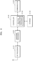
- FIG. 7 is a diagram for describing an operation when an MT receives smtc configuration to measure a normal neighbor cell, according to an embodiment.
- the MT may receive measurement configuration information from a serving cell.
- a measurement object and a report configuration may be transmitted in pair, wherein the report configuration is information indicating on which condition measurement of the measurement object is to be reported to the base station.
- the MT may identify reference signal configuration information included in the measurement object (MO) to identify whether the MO is an MO corresponding to an SSB to be measured. As a result of the identification, when the SSB is to be measured, the MT may again identify a measurement frequency through ssbFrequency information and may also identify subcarrier spacing information. Also, through ssbToMeasure, the terminal may be configured with an index of an SSB to be measured. Thereafter, the terminal may receive smtc1-related information and calculate an smtc occasion through the related information. Information included in the smtc1 may be smtc periodicity, offset value, and duration.
- the MT may measure an SSB for all cells in the calculated smtc occasion.
- FIG. 8 is a diagram for describing an operation when an MT receives smtc configuration and short-period smtc configuration to measure a normal neighbor cell, according to an embodiment.
- the MT may receive measurement configuration information from a serving cell.
- a measurement object and a report configuration may be transmitted in pair, wherein the report configuration is information indicating on which condition the MT is to report measurement of the measurement object to the base station.
- the MT may identify reference signal configuration information included in the measurement object (MO) to identify whether the MO is an MO corresponding to an SSB to be measured .
- the MT may again identify a measurement frequency through ssbFrequency information and may also identify subcarrier spacing information.
- the terminal may be configured with an index of an SSB to be measured. Thereafter, the terminal may receive smtc1-related information and calculate an smtc occasion through the related information.
- Information included in the smtc1 may be smtc periodicity, offset value, and duration.
- the MT may measure an SSB for all cells in the calculated smtc occasion.
- smtc2 may be configured together with smtc1 in a given measurement object, and a periodicity and a pci list may be separately included in smtc2.
- the MT may calculate an smtc2 occasion by applying an offset value and duration included in smtc1 and applying a periodicity value separately applied to smtc2.
- the terminal may perform SSB measurement in the smtc2 occasion only for the cells included in the pci list separately configured in smtc2.
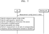
- FIG. 9 is a diagram for describing an operation when an MT receives smtc1, smtc2, and smtc3 configurations to measure a normal neighbor cell and an IAB node neighbor cell, according to an embodiment.
- the embodiment of FIG. 9 may correspond to a case where the MT ignores an smtc1 signal.
- the MT may receive measurement configuration information from a serving cell.
- a measurement object and a report configuration may be transmitted in pair, wherein the report configuration is information indicating on which condition measurement of the measurement object is to be reported to the base station.
- the MT may identify reference signal configuration information included in the measurement object (MO) to identify whether the MO is an MO corresponding to an SSB to be measured.
- the MT may again identify a measurement frequency through ssbFrequency information and may also identify subcarrier spacing information.
- the terminal may be configured with an index of an SSB to be measured. Thereafter, the terminal may receive smtc1-related information and calculate an smtc occasion through the related information.
- Information included in the smtc1 may be smtc periodicity, offset value, and duration. For a given frequency ssbFrequency, the MT may measure an SSB for all cells in the calculated smtc occasion.
- smtc3 information may be transmitted together with smtc1 in the MO.
- the smtc3 information may include smtc periodicity, offset, duration, ssbToMeasure, and pci list information.
- the MT may determine an smtc3 occasion through the periodicity, offset, and duration and measure an SSB id corresponding to given ssbToMeasure.
- an object to be measured may be limited to the cells existing in a given pci list.
- smtc3 may exist as a list, and periodicity, offset, duration, ssbToMeasure, and pci list may exist separately in each list.
- Smtc3 occasions may be determined by the number of lists according to the periodicity, offset, duration, ssbToMeasure, and pci list existing in each list, and the MT may measure an ssb only for the cells of the pci list associated with each of the multiple smtc3 occasions.
- the smtc3 information may be prioritized. That is, the MT may not measure all the cells in the smtc1 occasion but may only perform measurement corresponding to the smtc3 occasion.
- FIG. 10 is a diagram for describing an operation when an MT receives smtc1, smtc2, and smtc3 configurations to measure a normal neighbor cell and an IAB node neighbor cell.
- the embodiment of FIG. 10 may correspond to a case where the MT reuses some information of smtc1.
- the MT may receive measurement configuration information from a serving cell.
- a measurement object and a report configuration may be transmitted in pair, wherein the report configuration is information indicating on which condition measurement of the measurement object is to be reported to the base station.
- the MT may identify reference signal configuration information included in the measurement object (MO) to identify whether the MO is an MO corresponding to an SSB to be measured. As a result of the identification, when the MO corresponds to the SSB to be measured, the MT may again identify a measurement frequency through ssbFrequency information and may also identify subcarrier spacing information. Also, through ssbToMeasure, the terminal may be configured with an index of an SSB to be measured. Thereafter, the terminal may receive smtc1-related information and calculate an smtc occasion through the related information. Information included in the smtc1 may be smtc periodicity, offset value, and duration. For a given frequency ssbFrequency, the MT may measure an SSB for all cells in the calculated smtc occasion.
- Smtc3 information may be transmitted together with smtc1 in the MO.
- the smtc3 information may include smtc periodicity, offset, duration, ssbToMeasure, and pci list information.
- the portion may be replaced with information configured in smtc1.
- the MT may calculate the occasion of smtc3 by using the offset information in smtc1 and measure an ssb for the cells of the pci list corresponding thereto.
- the MT may determine an smtc3 occasion through the supplemented periodicity, offset, and duration and measure SSB ids corresponding to given ssbToMeasure.
- an object to be measured may be limited to the cells existing in a given pci list.
- smtc3 may exist as a list, and periodicity, offset, duration, ssbToMeasure, and pci list may exist separately in each list. Accordingly, smtc3 occasions may be determined by the number of lists, and the MT may measure an ssb only for the cells of the pci list associated with each of the multiple smtc3 occasions.
- the MT may perform ssb measurement on the smtc occasions of both smtc1 and smtc3.
- an ssb may be measured for all the cells in the case of smtc1
- an ssb may be measured only for the cells included in a given pci list in the case of smtc3.
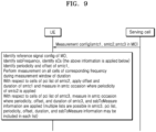
- FIG. 11 is a diagram for describing a case where a network configures only one of smtc1 or smtc3 when configuring a measurement object for measurement by an MT.
- Embodiment of FIG. 11 may correspond to a case where the network configures only one of smtc1 or smtc3 in one MO.
- related information may be conditionally configured in the MO.
- ssbFrequency information and ssbSubcarrierSpacing information may be configured only in the condition of SSBorAssociatedSSB2.
- Smtc1 information may be configured only in the condition of SSBorAssociatedSSB2.
- referenceSignalConfig information configured for the type of a reference signal may be configured only in the condition of Not_IABMT as conditional information instead of mandatory information. This is illustrated below.
- each condition may be as in the following table.
- SSBorAssociatedSS82 This field is mandatory present if ssb-ConfigMobility is configured or associatedSSB is configured in at least one cell or smtc3list is configured. Otherwise, it is absent, Need R.
- SSBorAssociatedSSB1 This field is mandatory present if ssb-ConfigMobility is configured or associatedSSB is configured in at least one cell. Otherwise, it is absent, Need R. Not_IABMT This field is mandatory present if smtc3 is not configured . Otherwise it is absent, Need R.
- a referenceSignalConfig field may not exist and ssb-ConfigMobility or associatedSSB information that may be configured therein may also not be configured. Accordingly, the smtc1 information may not exist.
- the MT may determine whether smtc1 or smtc3 exists.
- the terminal may identify the Periodicity and Offset of smtc1 and perform measurement on all the cells of the corresponding frequency during the measurement window of Duration. Additionally, the terminal may apply the offset and duration of smtc1 to the cells of the pci list of smtc2 and may perform measurement in an smtc occasion to which the periodicity of smtc2 is applied.
- the terminal may perform SSB measurement in an smtc3 occasion to which the periodicity, offset, duration, and ssbToMeasure information of smtc3 are applied, with respect to the cells of the pci list of smtc3. Also, multiple lists may be applied to smtc3. Each list may include pci list, periodicity, offset, duration, and ssbToMeasure information, and thus, the terminal may measure an ssb in multiple smtc3 occasions through the information included in each list.
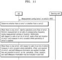
- FIG. 12 is a diagram for describing a case where a measurement object configured for measurement by an MT is specialized for detecting a neighbor lAB node, according to an embodiment.
- a new MO may be introduced.
- an indicator for configuring only smtc3 for an IAB node may be included in the MO itself, and a 1-bit indicator indicating a corresponding case may be included in the MO.
- Necessary information ssbFrequency, SCS, smtc3 list with each entry has smtc periodicity, offset, duration, pci list, ssb-toMeasure info. Or optionally indication for IAB MT purpose.
- the MO type may be configured only for the IAB MT by the network.
- the MT having received the MO may identify and apply ssbFrequency and SCS and may perform measurement in an smtc3 occasion to which the periodicity, offset, duration, and ssbToMeasure information of smtc3 are applied, with respect to the cells of the pci list of smtc3.
- lists may be maintained in smtc3, absolute radio frequency channel number (ARFCN) information for each particular channel raster may be mapped in each list, and the periodicity, offset, duration, and ssbToMeasure information may be separately configured in the list.
- ARFCN absolute radio frequency channel number
- the terminal may calculate a given smtc3 occasion and may measure an ssb in the calculated smtc3 occasion with respect to the cells of the pci list associated with the list at the frequency associated with the list.
- FIG. 13 is a diagram for describing a case where an MT adds multiple measurement frequency information in a measurement object according to capability or class, according to an embodiment.
- the MT may transmit information about whether its capability is wide area MT, medium area MT, or local area MT by indicating the same in a capability signaling message.
- a serving cell may receive the information through the capability signaling message, and when the capability of the MT or the class of the MT may perform SSB measurement for each of the multiple channel rasters associated with ssbFrequency without separate channel raster information, a base station may provide only ssbFrequency information and SCS and may provide the other smtc3 configuration information without separate channel raster information when configuring smtc3 for an MO.
- the base station may generate lists, may provide ARFCN information for broadcasting an SSB for each list, and may provide the other information necessary for an smtc occasion for each list when configuring smtc3 for the MO.
- the serving base station may provide smtc3 configuration information without separate channel raster frequency information, and when the MT transmits local area MT information, the serving base station may provide smtc3 configuration information including separate frequency information for the MO.
- the MT may perform measurement in an smtc occasion to which the periodicity, offset, duration, and ssbToMeasure information of smtc3 are applied, with respect to the cells of the pci list of smtc3.
- lists may be maintained in smtc3, ARFCN information for each particular channel raster may be mapped in each list, and the periodicity, offset, duration, ssbToMeasure, and pci list information may be separately configured for each entry in the list.
- the terminal may calculate an smtc3 occasion for each list entry and may measure an ssb in the calculated smtc3 occasion with respect to the cells of the pci list associated with the list entry at the frequency associated with the list entry.
- the terminal may detect and measure an SSB by performing blind detection of all particular bands based on the ssbFrequency frequency of the MO. Also, in this case, the SSB may be measured in the smtc3 occasion calculated with the given information with respect to the cells of the pci list provided for each list.
- a computer-readable storage medium may be provided to store one or more programs (software modules).
- the one or more programs stored in the computer-readable storage medium may be configured for execution by one or more processors in an electronic device.
- the one or more programs may include instructions for causing the electronic device to execute the methods according to the embodiments of the present disclosure described in the specification or the claims.
- RAMs random access memories
- nonvolatile memories including flash memories, read only memories (ROMs), electrically erasable programmable ROMs (EEPROMs), magnetic disc storage devices, compact disc-ROMs (CD-ROMs), digital versatile discs (DVDs), other types of optical storage devices, or magnetic cassettes.
- the programs may be stored in a memory including any combination of some or all thereof.
- each of the memories may be provided in plurality.
- the programs may be stored in an attachable storage device that may be accessed through a communication network such as Internet, Intranet, local area network (LAN), wide LAN (WLAN), or storage area network (SAN), or through a communication network configured as any combination thereof.
- a storage device may be connected through an external port to an apparatus performing an embodiment of the present disclosure.
- a separate storage device on a communication network may be connected to an apparatus performing an embodiment of the present disclosure.
- the components included in the present disclosure are expressed in the singular or plural according to the presented particular embodiments.
- the singular or plural expressions are selected suitably according to the presented situations for convenience of description, the present disclosure is not limited to the singular or plural components, and the components expressed in the plural may even be configured in the singular or the components expressed in the singular may even be configured in the plural.
Landscapes
- Engineering & Computer Science (AREA)
- Signal Processing (AREA)
- Computer Networks & Wireless Communication (AREA)
- Computer Security & Cryptography (AREA)
- Mobile Radio Communication Systems (AREA)
Applications Claiming Priority (2)
| Application Number | Priority Date | Filing Date | Title |
|---|---|---|---|
| KR1020200050318A KR102956342B1 (ko) | 2020-04-24 | 무선 통신 시스템에서 신호를 송수신하는 방법 및 장치 | |
| PCT/KR2021/005189 WO2021215884A1 (ko) | 2020-04-24 | 2021-04-23 | 무선 통신 시스템에서 신호를 송수신하는 방법 및 장치 |
Publications (3)
| Publication Number | Publication Date |
|---|---|
| EP4132082A1 true EP4132082A1 (de) | 2023-02-08 |
| EP4132082A4 EP4132082A4 (de) | 2023-07-12 |
| EP4132082B1 EP4132082B1 (de) | 2025-11-05 |
Family
ID=78269854
Family Applications (1)
| Application Number | Title | Priority Date | Filing Date |
|---|---|---|---|
| EP21792820.9A Active EP4132082B1 (de) | 2020-04-24 | 2021-04-23 | Verfahren und vorrichtung zum senden und empfangen von signalen in einem drahtloskommunikationssystem |
Country Status (3)
| Country | Link |
|---|---|
| US (1) | US12507101B2 (de) |
| EP (1) | EP4132082B1 (de) |
| WO (1) | WO2021215884A1 (de) |
Families Citing this family (4)
| Publication number | Priority date | Publication date | Assignee | Title |
|---|---|---|---|---|
| US11848709B2 (en) * | 2020-08-14 | 2023-12-19 | Huawei Technologies Co., Ltd. | Media-based reconfigurable intelligent surface-assisted modulation |
| KR102560539B1 (ko) * | 2021-12-06 | 2023-07-27 | 주식회사 블랙핀 | 비지상 네트워크에서 복수의 측정 시간 설정으로 주변 셀을 측정하는 방법 및 장치 |
| EP4445507A4 (de) * | 2021-12-07 | 2025-09-24 | Qualcomm Inc | Rückwärtskompatibler erstzugriff in einem schritt |
| US12432590B2 (en) * | 2022-01-05 | 2025-09-30 | Lg Electronics Inc. | Scheduling restriction and SMTC configuration for high frequency range |
Family Cites Families (11)
| Publication number | Priority date | Publication date | Assignee | Title |
|---|---|---|---|---|
| US10932147B2 (en) * | 2018-03-30 | 2021-02-23 | Mediatek Inc. | Gap-based cell measurement in wireless communication system |
| US10903942B2 (en) * | 2018-04-16 | 2021-01-26 | Qualcomm Incorporated | Synchronization signal block and downlink channel multiplexing |
| US20190313271A1 (en) | 2018-06-20 | 2019-10-10 | Intel Corporation | Apparatus, system and method of configuring new radio (nr) measurements |
| CN110896555B (zh) * | 2018-09-13 | 2023-06-02 | 华为技术有限公司 | 一种消息处理方法和装置 |
| WO2020060127A1 (ko) * | 2018-09-20 | 2020-03-26 | 한국전자통신연구원 | 통신 시스템에서 셀 정보를 포함하는 신호의 송수신을 위한 방법 및 장치 |
| WO2020067829A1 (en) * | 2018-09-28 | 2020-04-02 | Samsung Electronics Co., Ltd. | Integrated access backhaul configuration |
| WO2020129228A1 (ja) * | 2018-12-20 | 2020-06-25 | 株式会社Nttドコモ | 無線ノード、及び、無線通信方法 |
| US20210208602A1 (en) | 2019-07-12 | 2021-07-08 | Lg Electronics Inc. | Aerial control system |
| US20200374735A1 (en) | 2019-08-13 | 2020-11-26 | Intel Corporation | Signaling enhancements of smtc configuration for an iab mt |
| US11576137B2 (en) * | 2019-12-30 | 2023-02-07 | Qualcomm Incorporated | Synchronization signal block (SSB) configuration for power management |
| WO2021206506A1 (ko) * | 2020-04-09 | 2021-10-14 | 삼성전자 주식회사 | 백홀 및 액세스 홀 결합 시스템에서 du에게 ip 주소를 할당하는 방법 및 장치 |
-
2021
- 2021-04-23 US US17/919,879 patent/US12507101B2/en active Active
- 2021-04-23 EP EP21792820.9A patent/EP4132082B1/de active Active
- 2021-04-23 WO PCT/KR2021/005189 patent/WO2021215884A1/ko not_active Ceased
Also Published As
| Publication number | Publication date |
|---|---|
| EP4132082A4 (de) | 2023-07-12 |
| EP4132082B1 (de) | 2025-11-05 |
| US20230164601A1 (en) | 2023-05-25 |
| WO2021215884A1 (ko) | 2021-10-28 |
| KR20210131786A (ko) | 2021-11-03 |
| US12507101B2 (en) | 2025-12-23 |
Similar Documents
| Publication | Publication Date | Title |
|---|---|---|
| CN114051751B (zh) | 用于在下一代移动通信系统中测量和报告交叉链路干扰的方法和装置 | |
| KR20200114445A (ko) | 무선 통신 시스템에서 복수의 빔을 통해 신호를 송수신하는 방법 및 장치 | |
| EP4132082B1 (de) | Verfahren und vorrichtung zum senden und empfangen von signalen in einem drahtloskommunikationssystem | |
| US12096406B2 (en) | Method and apparatus for uplink transmission using MIMO in wireless communication system | |
| US20240284280A1 (en) | Method and device for supporting inter-cell movement based on l1 and l2 in wireless communication system | |
| US20230124607A1 (en) | Apparatus and method for conditional mobility on secondary node initiated by master node in wireless communication systems | |
| EP3923633A1 (de) | Verfahren und vorrichtung zur übergabe in einem mobilen kommunikationssystem der nächsten generation | |
| EP4304246A1 (de) | Betriebsverfahren zur koexistenz von bedingter mobilität in einem mobilkommunikationssystem der nächsten generation | |
| US20240292308A1 (en) | Method and apparatus for handover of a user equipment for network energy saving in next generation mobile communication system | |
| US20240155445A1 (en) | Method of configuring handover using physical layer and mac layer signaling in next generation mobile communication system | |
| US20240056935A1 (en) | Method and device for performing conditional handover in wireless communication system | |
| CN113647146B (zh) | 用于下一代移动通信系统中的切换方法和装置 | |
| US20240107387A1 (en) | Method and apparatus for measurement reporting of uncrewed aerial vehicle terminal in non-terrestrial network | |
| EP4734429A1 (de) | Verfahren und vorrichtung zur unterstützung mehrerer trp-operationen auf basis eines verbesserten pdcch unter verwendung eines integrierten tci-rahmens in einem mobilkommunikationssystem der nächsten generation | |
| US12348994B2 (en) | Method and apparatus for configuring measurement of channel pathloss for plurality of TRPs in wireless communication system | |
| KR20230123827A (ko) | 차세대 이동통신 시스템에서 조건부 PSCell 변경 방법 및 장치 | |
| KR20230123683A (ko) | 무선 통신 시스템에서 조건부 pscell 변경을 위한 단말 능력 신호 방법 | |
| US20260129613A1 (en) | Method and apparatus for performing lower-layer triggered mobility of user equipment using conditions in a wireless communication system | |
| US20250280334A1 (en) | Apparatus and method for measurement and report of physical layer reference signal in next-generation mobile communication system | |
| US20250039756A1 (en) | Method and apparatus for conditional reconfiguration of user equipment and base station in wireless communication system | |
| US20260052431A1 (en) | Method and apparatus for configuring candidate pscell during conditional handover in next-generation mobile communication | |
| US20260129541A1 (en) | Method and apparatus for using condition and non-condition during lower-layer triggered mobility of terminal in wireless communication systems | |
| EP4668869A1 (de) | Verfahren und vorrichtung zur verarbeitung von konfigurationsinformationen von durch eine niedrigere schicht ausgelöster mobilität in einem drahtloskommunikationssystem | |
| US20250039748A1 (en) | Method and apparatus for evaluating condition for sequential conditional pscell change in next generation mobile communication system | |
| US20250151151A1 (en) | Method and apparatus for reporting enhanced early measurement result in next generation mobile communication system |
Legal Events
| Date | Code | Title | Description |
|---|---|---|---|
| STAA | Information on the status of an ep patent application or granted ep patent |
Free format text: STATUS: THE INTERNATIONAL PUBLICATION HAS BEEN MADE |
|
| PUAI | Public reference made under article 153(3) epc to a published international application that has entered the european phase |
Free format text: ORIGINAL CODE: 0009012 |
|
| STAA | Information on the status of an ep patent application or granted ep patent |
Free format text: STATUS: REQUEST FOR EXAMINATION WAS MADE |
|
| 17P | Request for examination filed |
Effective date: 20221025 |
|
| AK | Designated contracting states |
Kind code of ref document: A1 Designated state(s): AL AT BE BG CH CY CZ DE DK EE ES FI FR GB GR HR HU IE IS IT LI LT LU LV MC MK MT NL NO PL PT RO RS SE SI SK SM TR |
|
| REG | Reference to a national code |
Ref country code: DE Ref legal event code: R079 Free format text: PREVIOUS MAIN CLASS: H04W0024100000 Ipc: H04W0048160000 Ref document number: 602021041877 Country of ref document: DE |
|
| A4 | Supplementary search report drawn up and despatched |
Effective date: 20230613 |
|
| RIC1 | Information provided on ipc code assigned before grant |
Ipc: H04W 24/10 20090101ALN20230606BHEP Ipc: H04L 5/00 20060101ALI20230606BHEP Ipc: H04W 48/16 20090101AFI20230606BHEP |
|
| DAV | Request for validation of the european patent (deleted) | ||
| DAX | Request for extension of the european patent (deleted) | ||
| GRAP | Despatch of communication of intention to grant a patent |
Free format text: ORIGINAL CODE: EPIDOSNIGR1 |
|
| STAA | Information on the status of an ep patent application or granted ep patent |
Free format text: STATUS: GRANT OF PATENT IS INTENDED |
|
| RIC1 | Information provided on ipc code assigned before grant |
Ipc: H04W 24/10 20090101ALN20250521BHEP Ipc: H04L 5/00 20060101ALI20250521BHEP Ipc: H04W 48/16 20090101AFI20250521BHEP |
|
| INTG | Intention to grant announced |
Effective date: 20250605 |
|
| GRAS | Grant fee paid |
Free format text: ORIGINAL CODE: EPIDOSNIGR3 |
|
| GRAA | (expected) grant |
Free format text: ORIGINAL CODE: 0009210 |
|
| STAA | Information on the status of an ep patent application or granted ep patent |
Free format text: STATUS: THE PATENT HAS BEEN GRANTED |
|
| AK | Designated contracting states |
Kind code of ref document: B1 Designated state(s): AL AT BE BG CH CY CZ DE DK EE ES FI FR GB GR HR HU IE IS IT LI LT LU LV MC MK MT NL NO PL PT RO RS SE SI SK SM TR |
|
| REG | Reference to a national code |
Ref country code: CH Ref legal event code: F10 Free format text: ST27 STATUS EVENT CODE: U-0-0-F10-F00 (AS PROVIDED BY THE NATIONAL OFFICE) Effective date: 20251105 Ref country code: GB Ref legal event code: FG4D |
|
| REG | Reference to a national code |
Ref country code: DE Ref legal event code: R096 Ref document number: 602021041877 Country of ref document: DE |
|
| REG | Reference to a national code |
Ref country code: IE Ref legal event code: FG4D |
|
| REG | Reference to a national code |
Ref country code: NL Ref legal event code: MP Effective date: 20251105 |
|
| PG25 | Lapsed in a contracting state [announced via postgrant information from national office to epo] |
Ref country code: ES Free format text: LAPSE BECAUSE OF FAILURE TO SUBMIT A TRANSLATION OF THE DESCRIPTION OR TO PAY THE FEE WITHIN THE PRESCRIBED TIME-LIMIT Effective date: 20251105 |
|
| REG | Reference to a national code |
Ref country code: LT Ref legal event code: MG9D |
|
| PG25 | Lapsed in a contracting state [announced via postgrant information from national office to epo] |
Ref country code: NO Free format text: LAPSE BECAUSE OF FAILURE TO SUBMIT A TRANSLATION OF THE DESCRIPTION OR TO PAY THE FEE WITHIN THE PRESCRIBED TIME-LIMIT Effective date: 20260205 |
|
| PG25 | Lapsed in a contracting state [announced via postgrant information from national office to epo] |
Ref country code: HR Free format text: LAPSE BECAUSE OF FAILURE TO SUBMIT A TRANSLATION OF THE DESCRIPTION OR TO PAY THE FEE WITHIN THE PRESCRIBED TIME-LIMIT Effective date: 20251105 Ref country code: AT Free format text: LAPSE BECAUSE OF FAILURE TO SUBMIT A TRANSLATION OF THE DESCRIPTION OR TO PAY THE FEE WITHIN THE PRESCRIBED TIME-LIMIT Effective date: 20251105 Ref country code: FI Free format text: LAPSE BECAUSE OF FAILURE TO SUBMIT A TRANSLATION OF THE DESCRIPTION OR TO PAY THE FEE WITHIN THE PRESCRIBED TIME-LIMIT Effective date: 20251105 |
|
| REG | Reference to a national code |
Ref country code: AT Ref legal event code: MK05 Ref document number: 1855789 Country of ref document: AT Kind code of ref document: T Effective date: 20251105 |
|
| PG25 | Lapsed in a contracting state [announced via postgrant information from national office to epo] |
Ref country code: NL Free format text: LAPSE BECAUSE OF FAILURE TO SUBMIT A TRANSLATION OF THE DESCRIPTION OR TO PAY THE FEE WITHIN THE PRESCRIBED TIME-LIMIT Effective date: 20251105 |
|
| PG25 | Lapsed in a contracting state [announced via postgrant information from national office to epo] |
Ref country code: RS Free format text: LAPSE BECAUSE OF FAILURE TO SUBMIT A TRANSLATION OF THE DESCRIPTION OR TO PAY THE FEE WITHIN THE PRESCRIBED TIME-LIMIT Effective date: 20260205 |
|
| PG25 | Lapsed in a contracting state [announced via postgrant information from national office to epo] |
Ref country code: IS Free format text: LAPSE BECAUSE OF FAILURE TO SUBMIT A TRANSLATION OF THE DESCRIPTION OR TO PAY THE FEE WITHIN THE PRESCRIBED TIME-LIMIT Effective date: 20260305 |
|
| PG25 | Lapsed in a contracting state [announced via postgrant information from national office to epo] |
Ref country code: PT Free format text: LAPSE BECAUSE OF FAILURE TO SUBMIT A TRANSLATION OF THE DESCRIPTION OR TO PAY THE FEE WITHIN THE PRESCRIBED TIME-LIMIT Effective date: 20260305 |
|
| PG25 | Lapsed in a contracting state [announced via postgrant information from national office to epo] |
Ref country code: PL Free format text: LAPSE BECAUSE OF FAILURE TO SUBMIT A TRANSLATION OF THE DESCRIPTION OR TO PAY THE FEE WITHIN THE PRESCRIBED TIME-LIMIT Effective date: 20251105 |
|
| PG25 | Lapsed in a contracting state [announced via postgrant information from national office to epo] |
Ref country code: LV Free format text: LAPSE BECAUSE OF FAILURE TO SUBMIT A TRANSLATION OF THE DESCRIPTION OR TO PAY THE FEE WITHIN THE PRESCRIBED TIME-LIMIT Effective date: 20251105 |