EP4132085A1 - Procédé et appareil de communication - Google Patents
Procédé et appareil de communication Download PDFInfo
- Publication number
- EP4132085A1 EP4132085A1 EP20932636.2A EP20932636A EP4132085A1 EP 4132085 A1 EP4132085 A1 EP 4132085A1 EP 20932636 A EP20932636 A EP 20932636A EP 4132085 A1 EP4132085 A1 EP 4132085A1
- Authority
- EP
- European Patent Office
- Prior art keywords
- indication information
- data packet
- data
- synchronous transmission
- network element
- Prior art date
- Legal status (The legal status is an assumption and is not a legal conclusion. Google has not performed a legal analysis and makes no representation as to the accuracy of the status listed.)
- Pending
Links
Images


Classifications
-
- H—ELECTRICITY
- H04—ELECTRIC COMMUNICATION TECHNIQUE
- H04L—TRANSMISSION OF DIGITAL INFORMATION, e.g. TELEGRAPHIC COMMUNICATION
- H04L47/00—Traffic control in data switching networks
- H04L47/10—Flow control; Congestion control
- H04L47/24—Traffic characterised by specific attributes, e.g. priority or QoS
- H04L47/2483—Traffic characterised by specific attributes, e.g. priority or QoS involving identification of individual flows
-
- H—ELECTRICITY
- H04—ELECTRIC COMMUNICATION TECHNIQUE
- H04L—TRANSMISSION OF DIGITAL INFORMATION, e.g. TELEGRAPHIC COMMUNICATION
- H04L47/00—Traffic control in data switching networks
- H04L47/10—Flow control; Congestion control
- H04L47/32—Flow control; Congestion control by discarding or delaying data units, e.g. packets or frames
-
- H—ELECTRICITY
- H04—ELECTRIC COMMUNICATION TECHNIQUE
- H04L—TRANSMISSION OF DIGITAL INFORMATION, e.g. TELEGRAPHIC COMMUNICATION
- H04L47/00—Traffic control in data switching networks
- H04L47/10—Flow control; Congestion control
- H04L47/24—Traffic characterised by specific attributes, e.g. priority or QoS
- H04L47/2408—Traffic characterised by specific attributes, e.g. priority or QoS for supporting different services, e.g. a differentiated services [DiffServ] type of service
-
- H—ELECTRICITY
- H04—ELECTRIC COMMUNICATION TECHNIQUE
- H04L—TRANSMISSION OF DIGITAL INFORMATION, e.g. TELEGRAPHIC COMMUNICATION
- H04L47/00—Traffic control in data switching networks
- H04L47/10—Flow control; Congestion control
- H04L47/24—Traffic characterised by specific attributes, e.g. priority or QoS
- H04L47/2425—Traffic characterised by specific attributes, e.g. priority or QoS for supporting services specification, e.g. SLA
- H04L47/2433—Allocation of priorities to traffic types
-
- H—ELECTRICITY
- H04—ELECTRIC COMMUNICATION TECHNIQUE
- H04L—TRANSMISSION OF DIGITAL INFORMATION, e.g. TELEGRAPHIC COMMUNICATION
- H04L47/00—Traffic control in data switching networks
- H04L47/10—Flow control; Congestion control
- H04L47/28—Flow control; Congestion control in relation to timing considerations
-
- H—ELECTRICITY
- H04—ELECTRIC COMMUNICATION TECHNIQUE
- H04L—TRANSMISSION OF DIGITAL INFORMATION, e.g. TELEGRAPHIC COMMUNICATION
- H04L47/00—Traffic control in data switching networks
- H04L47/10—Flow control; Congestion control
- H04L47/31—Flow control; Congestion control by tagging of packets, e.g. using discard eligibility [DE] bits
-
- H—ELECTRICITY
- H04—ELECTRIC COMMUNICATION TECHNIQUE
- H04L—TRANSMISSION OF DIGITAL INFORMATION, e.g. TELEGRAPHIC COMMUNICATION
- H04L47/00—Traffic control in data switching networks
- H04L47/10—Flow control; Congestion control
- H04L47/35—Flow control; Congestion control by embedding flow control information in regular packets, e.g. piggybacking
-
- H—ELECTRICITY
- H04—ELECTRIC COMMUNICATION TECHNIQUE
- H04W—WIRELESS COMMUNICATION NETWORKS
- H04W28/00—Network traffic management; Network resource management
- H04W28/02—Traffic management, e.g. flow control or congestion control
- H04W28/0268—Traffic management, e.g. flow control or congestion control using specific QoS parameters for wireless networks, e.g. QoS class identifier [QCI] or guaranteed bit rate [GBR]
-
- H—ELECTRICITY
- H04—ELECTRIC COMMUNICATION TECHNIQUE
- H04L—TRANSMISSION OF DIGITAL INFORMATION, e.g. TELEGRAPHIC COMMUNICATION
- H04L45/00—Routing or path finding of packets in data switching networks
- H04L45/12—Shortest path evaluation
- H04L45/121—Shortest path evaluation by minimising delays
-
- H—ELECTRICITY
- H04—ELECTRIC COMMUNICATION TECHNIQUE
- H04L—TRANSMISSION OF DIGITAL INFORMATION, e.g. TELEGRAPHIC COMMUNICATION
- H04L47/00—Traffic control in data switching networks
- H04L47/10—Flow control; Congestion control
- H04L47/12—Avoiding congestion; Recovering from congestion
- H04L47/125—Avoiding congestion; Recovering from congestion by balancing the load, e.g. traffic engineering
-
- H—ELECTRICITY
- H04—ELECTRIC COMMUNICATION TECHNIQUE
- H04L—TRANSMISSION OF DIGITAL INFORMATION, e.g. TELEGRAPHIC COMMUNICATION
- H04L47/00—Traffic control in data switching networks
- H04L47/70—Admission control; Resource allocation
- H04L47/80—Actions related to the user profile or the type of traffic
- H04L47/805—QOS or priority aware
Definitions
- This application relates to the field of communication technologies, and in particular, to a communication method and apparatus.
- a user plane network element After a protocol data unit (protocol data unit, PDU) session is established, a user plane network element views a quintuple of a received data packet, matches a data flow to which the data packet belongs, and then processes the data packet based on a parameter required for data packet processing. However, the user plane network element identifies, by using the quintuple carried in the data packet, a service flow to which the data packet belongs, and performs a unified operation on the data packet of the service flow. Because differentiated processing cannot be performed on different data packets in one service flow, it is difficult to adapt to and meet a temporary requirement change of a user or a network condition change.
- PDU protocol data unit
- Embodiments of this application provide a communication method and apparatus, to resolve a problem that when performing a unified operation on a data flow, a user plane network element cannot meet a temporary requirement change of a user, a network condition change, or the like.
- an embodiment of this application provides a communication method.
- the method includes: receiving a first data packet, where the first data packet carries first indication information; and processing the first data packet based on the first indication information, where the first indication information includes one or more of the following: synchronous transmission indication information, packet discard indication information, data type indication information, charging indication information, statistics indication information, or priority indication information.
- the first data packet is a data packet in a first data flow
- the second data packet is a data packet in a second data flow.
- the first indication information includes the packet discard indication information.
- the first data packet may be discarded based on the packet discard indication information when network congestion occurs; or after the first data packet is received, the first data packet may be discarded based on the packet discard indication information when it is identified that transmission duration of the first data packet exceeds a delay threshold, where the delay threshold is received by the first user plane network element from a first control plane network element or the first data packet carries the delay threshold.
- packet discard processing at the packet granularity may be implemented.
- the first indication information includes the data type indication information
- the data type indication information indicates a video frame type of the first data packet
- the video frame type includes one or more of the following: an I-frame, a P-frame, or a B-frame.
- Quality of service QoS guarantee provided by the first user plane network element for a data packet whose video frame type is the I-frame is higher than QoS guarantee provided for a data packet whose video frame type is the P-frame or the B-frame. In this way, QoS guarantee at the packet granularity may be implemented.
- the first indication information includes the statistics indication information.
- a statistics rule indicated by the statistics indication information may be executed for the first data packet. In this way, statistics or statistics-free at the packet granularity may be implemented.
- the first indication information includes the priority indication information, and the priority indication information includes a high priority.
- the first data packet may be transmitted when network congestion occurs; or after the first data packet is received, QoS guarantee of the first data packet may be improved when it is identified that the transmission duration of the first data packet exceeds the delay threshold.
- preferential processing at the packet granularity may be implemented, for example, preferably transmitting the data packet or improving QoS guarantee of the data packet.
- the first data packet includes a first field
- the first field includes the first indication information
- the first indication information indicates a data packet processing type and/or a parameter required for data processing
- the first field indicates the first user plane network element to process the first data packet.
- this embodiment of this application provides a new data packet format, to adapt to data processing at the packet granularity.
- the data packet processing type includes one or more of the following: synchronous transmission, packet discard processing, routing selection, charging or charging-free processing, statistics or statistics-free processing, improving or reducing a priority, or improving or reducing QoS.
- first configuration information from the first control plane network element may be further received, where the first configuration information includes one or more of the following: the synchronous transmission indication information, the packet discard indication information, the data type indication information, the charging indication information, the statistics indication information, or the priority indication information.
- the first data packet When the first data packet is processed based on the first indication information, if a data processing type indicated by the first indication information is associated with a data processing type indicated by the first configuration information, the first data packet may be processed based on the first indication information.
- the first configuration information includes the synchronous transmission indication information, and a first synchronous transmission identifier and/or a synchronous transmission precision requirement may be further received, where the first synchronous transmission identifier indicates the first user plane network element to perform synchronous transmission on a data packet that carries a synchronous transmission identifier associated with the first synchronous transmission identifier.
- the first indication information includes the synchronous transmission indication information
- the first data packet is a data packet generated by an access network element by adding the synchronous transmission indication information to a second data packet
- the second data packet comes from a terminal device or a server
- the second data packet carries a second synchronous transmission identifier
- an embodiment of this application provides a communication method.
- the method includes: generating a first data packet, where the first data packet carries first indication information; and sending the first data packet, where the first indication information includes one or more of the following: synchronous transmission indication information, packet discard indication information, data type indication information, charging indication information, statistics indication information, or priority indication information.
- the communication method provided in this embodiment of this application may be applied to a terminal device or a server.
- refined differentiated processing may be performed, on a user plane network element, on different data packets at a granularity of a data packet by carrying indication information in the data packet. Compared with data processing performed at a granularity of a data flow, this may better adapt to and meet different user requirements, a network condition change, and the like.
- the first indication information includes the packet discard indication information and/or the priority indication information, and the first data packet further carries a delay threshold.
- a first request message may be further sent, where the first request message requests to establish or modify a session, the first request message includes information about a data packet processing type and/or identification information corresponding to a data flow, and the identification information corresponding to the data flow requests to process a data packet in a data flow of the identification information.
- the second configuration information includes the synchronous transmission indication information, and a first synchronous transmission identifier may be further received, where the first synchronous transmission identifier indicates a first user plane network element to perform synchronous transmission on a data packet that carries a synchronous transmission identifier associated with the first synchronous transmission identifier.
- an embodiment of this application provides a communication method.
- the method includes: delivering configuration information, where the configuration information includes one or more of the following: synchronous transmission indication information, packet discard indication information, data type indication information, charging indication information, statistics indication information, or priority indication information.
- a first request message may be further received, where the first request message requests to establish or modify a session, the first request message includes information about a data packet processing type and/or identification information corresponding to a data flow, and the identification information corresponding to the data flow requests to process a data packet in a data flow of the identification information.
- a first user plane network element that has a processing capability required for the data packet processing type is selected based on the information about the data packet processing type.
- the data packet processing type includes one or more of the following: synchronous transmission, packet discard processing, routing selection, charging or charging-free processing, statistics or statistics-free processing, improving or reducing a priority, or improving or reducing QoS.
- the data packet processing type includes synchronous transmission
- a first synchronous transmission identifier may be further allocated based on a synchronous transmission type and the identification information corresponding to the data flow.
- an embodiment of this application provides a communication apparatus.
- the communication has a function of implementing any one of the first aspect and the possible implementations of the first aspect, a function of implementing any one of the second aspect and the possible implementations of the second aspect, or a function of implementing any one of the third aspect and the possible implementations of the third aspect.
- the function may be implemented by hardware, or may be implemented by hardware by executing corresponding software.
- the hardware or software includes one or more function modules corresponding to the foregoing function.
- an embodiment of this application provides a chip system, where the chip system includes a processor and a memory, the processor and the memory are electrically coupled to each other.
- the memory is configured to store computer program instructions.
- the processor is configured to execute some or all of the computer program instructions in the memory. When the some or all of the computer program instructions are executed, a function of the user plane network element in the method according to any one of the first aspect and the possible implementations of the first aspect is implemented, a function of the terminal device in the method according to any one of the second aspect and the possible implementations of the second aspect is implemented, or a function of the control plane network element in the method according to any one of the third aspect and the possible implementations of the third aspect is implemented.
- an embodiment of this application provides a communication system.
- the system includes the user plane network element that performs the method in any one of the first aspect and the possible implementations of the first aspect, and the terminal device that performs the method in any one of the second aspect and the possible implementations of the second aspect.
- example in embodiments of this application is used to represent giving an example, an illustration, or a description. Any embodiment or design described as an “example” in this application should not be explained as being more preferred or having more advantages than another embodiment or design. Exactly, the term “example” is used to present a concept in a specific manner.
- a network architecture and a service scenario that are described in embodiments of this application are intended to describe technical solutions in embodiments of this application more clearly, but constitute no limitation on the technical solutions provided in embodiments of this application.
- a person of ordinary skill in the art may know that, with evolution of the network architecture and emergence of new service scenarios, the technical solutions provided in embodiments of this application are also applicable to similar technical problems.
- the terminal device may alternatively be a wearable device.
- the wearable device may also be referred to as a wearable intelligent device, an intelligent wearable device, or the like, and is a general term of wearable devices that are intelligently designed and developed for daily wear by using a wearable technology, for example, glasses, gloves, watches, clothes, and shoes.
- the wearable device is a portable device that can be directly worn on the body or integrated into clothes or an accessory of a user.
- the wearable device is not only a hardware device, but also implements a powerful function through software support, data exchange, and cloud interaction.
- wearable intelligent devices include full-featured and large-sized devices that can implement all or some functions without depending on smartphones, for example, smart watches or smart glasses, and include devices that focus on only one type of application function and need to collaboratively work with other devices such as smartphones, for example, various smart bands, smart helmets, or smart jewelry for monitoring physical signs.
- the terminal devices described above are located in a vehicle (for example, placed in the vehicle or installed in the vehicle), the terminal devices may be all considered as vehicle-mounted terminal devices.
- the vehicle-mounted terminal devices are also referred to as on-board units (on-board units, OBUs).
- the terminal device may further include a relay (relay).
- a relay relay
- any device that can perform data communication with a base station may be considered as the terminal device.
- the RSU may be a fixed infrastructure entity supporting a V2X application, and may exchange a message with another entity supporting the V2X application.
- the network device may further coordinate attribute management of the air interface.
- the network device may include an evolved NodeB (NodeB, eNB, or e-NodeB, evolved NodeB) in a long term evolution (long term evolution, LTE) system or a long term evolution-advanced (long term evolution-advanced, LTE-A) system, may include a next generation NodeB (next generation NodeB, gNB) in a 5th generation (a 5th generation, 5G) mobile communication technology NR system (also briefly referred to as an NR system), or may include a centralized unit (centralized unit, CU) and a distributed unit (distributed unit, DU) in a cloud radio access network (cloud radio access network, Cloud RAN) system.
- This is not limited in embodiments of this application.
- the network device may further include a core network (core network, CN) device, and the core network device includes, for example, an access and mobility management function (access and mobility management function, AMF).
- core network core network, CN
- AMF access and mobility management function
- the service flow includes a series of data packets with a same quintuple. To be specific, the series of data packets with the same quintuple belong to the same service flow.
- the service flow may be uniquely identified by the quintuple carried in the data packet.
- the quintuple includes a source address, a destination address, a source port number, a destination port number, and a protocol type (for example, a transmission layer protocol).
- the service flow may also be referred to as a data flow, or referred to as a flow for short, and the data packet may also be referred to as a packet for short.
- a plurality of in this application means two or more.
- a global system for mobile communication global system of mobile communication, GSM
- GSM global system of mobile communication
- CDMA code division multiple access
- WCDMA Wideband Code Division Multiple access
- general packet radio service general packet radio service, GPRS
- LTE LTE frequency division duplex
- FDD frequency division duplex
- TDD time division duplex
- UMTS universal mobile communication system
- WiMAX worldwide interoperability for microwave access
- WiMAX worldwide interoperability for microwave access
- a 5G network architecture shown in FIG. 1 is used as an example to describe an application scenario used in this application. It may be understood that, for another communication network architecture similar to the 5G network architecture, details are not described.
- the 5G network device architecture shown in FIG. 1 may include a terminal device part, a data network (data network, DN), and an operator network part. The following briefly describes functions of some network elements.
- the operator network may include one or more of the following network elements: an authentication server function (Authentication Server Function, AUSF) network element, a network exposure function (network exposure function, NEF) network element, a policy control function (policy control function, PCF) network element, a unified data management (unified data management, UDM) network element, a unified data repository (Unified Data Repository, UDR) (not shown in the figure), an unstructured data storage function (unstructured data storage function, UDSF) (not shown in the figure), a network repository function (Network Repository Function, NRF) network element, an application function (application function, AF) network element, an access and mobility management function (access and mobility management function, AMF) network element, a session management function (session management function, SMF) network element, a radio access network (radio access network, RAN) network element, a user plane function (user plane function, UPF) network element, a network slice selection function (Network Slice Selection Function, NSSF) network element, and the like.
- a user plane network element may include a (R)AN, the UPF network element, and a DN
- a control plane network element may include the AUSF network element, the UDM network element, the AMF network element, an SFM network element, a PFC network element, and the AF network element.
- the terminal device may also be referred to as user equipment (user equipment, UE), and is a device that is used by a user and that has a wireless receiving and sending function.
- user equipment user equipment
- the (R)AN is a subnetwork of the operator network and an implementation system between a service node on the operator network and the terminal device.
- the terminal device To connect to the operator network, the terminal device first connects to the (R)AN and then may be connected to the service node of the operator network by using the (R)AN.
- a (R)AN device is a device that provides a wireless communication function for the terminal device, and the RAN device is also referred to as an access network device.
- the RAN device in this application includes but is not limited to: a gNB, an eNB, a radio network controller (radio network controller, RNC), a NodeB (NodeB, NB), a base station controller (base station controller, BSC), a base transceiver station (base transceiver station, BTS), a home evolved NodeB (for example, a home evolved NodeB, or a home NodeB, HNB), a baseband unit (baseband unit, BBU), a transmission reception point (transmitting and receiving point, TRP), and a transmitting point (transmitting point, TP), a mobile switching center, and the like.
- RNC radio network controller
- NodeB NodeB
- BSC base station controller
- BTS base transceiver station
- BTS base transceiver station
- HNB home evolved NodeB
- BBU baseband unit
- TRP transmission reception point
- TP transmitting point
- the AMF network element is responsible for management such as user access and mobility.
- Functions of the AMF include: termination of non-access stratum (Non-Access Stratum, NAS) signaling security, user registration, reachability, mobility management, N1/N2 interface signaling transmission, access authentication and authorization, and the like.
- Non-Access Stratum Non-Access Stratum
- the SMF network element provides session management (for example, session establishment, modification, or release), internet protocol (internet protocol, IP) address allocation and management, UPF selection and control, and the like for a session of the terminal device.
- session management for example, session establishment, modification, or release
- internet protocol internet protocol, IP
- the UPF network element serves as an interface UPF of a data network, and provides functions such as user packet forwarding and processing, charging statistics based on a session/flow level, bandwidth throttling, and quality of service (quality of service, QoS) policy execution.
- the UDM network element is mainly responsible for functions such as subscription data management, user access authorization, and authentication information generation.
- the NEF network element is mainly configured to support capability and event exposure, and receive related external information.
- the AF network element represents that the AF network element is applied to another control network element for interaction, including providing a service QoS policy requirement, a routing policy requirement, and the like.
- An AF may be a third-party functional entity or an application service deployed by an operator, for example, an IMS voice call service.
- the UDR network element provides a capability of storing subscription data, policy data, and capability exposure data.
- the UDSF can store unstructured data of each network element.
- the PCF network element is responsible for generating a terminal device access policy and a QoS flow control policy.
- the NRF network element may be configured to provide a network element discovery function and provide, based on a request from another network element, network element information corresponding to a network element type.
- the NRF further provides a network element management service, for example, registration, update, and deregistration of a network element and subscription and push of a network element status.
- the AUSF network element is mainly responsible for user authentication, to determine whether to allow a user or a device to access a network.
- the NSSF network element is mainly configured to: select a network slice, perform user counting on the network slice, and the like.
- the DN is a network outside the operator network.
- the operator network may access a plurality of DNs.
- a plurality of services may be deployed in the DN, and the DN may provide services such as a data service and/or a voice service for the terminal device.
- the DN may be identified by a data network name (data network name, DNN) in a 5G network.
- DNN data network name
- the DN includes the Internet (Internet), an IP multimedia subsystem (IP multimedia subsystem, IMS) network, and the like.
- Nnssf, Nausf, Nnef, Npcf, Nudm, Naf, Namf, Nsmf, N1, N2, N3, N4, N6, and N9 are interface sequence numbers.
- meanings of these interface sequence numbers refer to meanings defined in the 3rd generation partnership project (3rd generation partnership project, 3GPP) standard protocol. This is not limited herein.
- the schematic diagram of the network architecture shown in FIG. 1 may be understood as a schematic diagram of a service-based 5G network architecture in a non-roaming scenario. Embodiments of this application are also applicable to a roaming scenario.
- a PDU session may be used to establish a user plane transmission channel for a terminal device.
- the PDU session also referred to as a "session" establishment procedure is used to create a new PDU session for the terminal device, and allocate an end-to-end user plane connection resource between the terminal device and an anchor UPF network element.
- FIG. 2 is a schematic diagram of a PDU session (session) establishment procedure, including the following process.
- S201 A terminal device sends a PDU session establishment request to an AMF network element.
- the AMF network element selects an SMF network element.
- S203 Establish a PDU session management context between the AMF network element and the SMF network element.
- the SMF network element obtains session subscription information from a UDM network element.
- a session management subscription data includes information such as a session type, a default session parameter value, and a subscribed session aggregate maximum bit rate (aggregate maximum bit rate, AMBR).
- AMBR aggregate maximum bit rate
- S205 The SMF network element performs PDU session granularity authentication and authorization.
- the SMF network element and a third-party authentication, authorization, and accounting (authentication authorization accounting, AAA) server in a DN perform secondary authentication and authorization on a PDU session.
- AAA authentication authorization accounting
- the SMF network element selects a PCF network element and a UPF network element for the PDU session.
- the SMF network element obtains session policy information from the PCF network element, to implement session policy authorization.
- S208 Establish an end-to-end user plane path between the terminal device, a (R)AN, and the UPF network element.
- the UPF network element and/or the terminal device may obtain, from a control plane network element (for example, the SMF network element), a parameter required for data packet processing.
- a service flow 1 transmits the data packet by using a QoS parameter 1
- a service flow 2 performs packet discard processing
- a service flow 3 transmits the data packet by using a QoS parameter 2.
- S209 The SMF network element registers with UDM network element, and the UDM network element records an SMF identifier corresponding to the PDU session.
- the SMF network element allocates an IPv6 prefix to the terminal device.
- the SMF network element When the session type is IPv6 or IP v4v6, the SMF network element generates a router advertisement (router advertisement, RA) message that carries the IPv6 prefix allocated for the session, and sends the message to the terminal device through a user plane.
- a router advertisement route advertisement, RA
- the UPF network element and/or the terminal device view/views a quintuple of the data packet, match/matches a data flow to which the data packet belongs, and then process/processes the data packet based on the parameter that is required for data packet processing and that is obtained in S108.
- the data packet in the service flow 1 is transmitted by using the QoS parameter 1
- packet discard processing is performed on the data packet in the service flow 2
- the data packet in the service flow 3 is transmitted by using the QoS parameter 2.
- a user plane network element identifies, by using the quintuple carried in the data packet, the service flow to which the data packet belongs, and performs a unified operation on the data packet of the service flow. Because differentiated processing cannot be performed on different data packets in one service flow, it is difficult to adapt to and meet a temporary requirement change of a user or a network condition change.
- this application provides a communication method.
- the terminal device sends the data packet that carries first indication information, where the first indication information includes one or more of synchronous transmission indication information, packet discard indication information, data type indication information, charging indication information, statistics indication information, or priority indication information.
- the user plane network element may perform corresponding processing on the received data packet based on the first indication information in the received data packet, so that the user plane network element can perform refined differentiated processing on different data packets, to ensure to adapt to and meet different user requirements and network conditions.
- a control granularity implements control at a (data) packet granularity instead of a (data) flow granularity.
- the communication method provided in this embodiment of this application may be applied to a communication system shown in FIG. 1 . It may be understood that the communication method provided in this application mainly uses an example in which a first user plane network element is the UPF network element, and is also applicable to another user plane network element (for example, the (R)AN); uses the terminal device as an example, and is also applicable to a server; and uses an example in which a first control plane network element is the SMF network element, and is also applicable to another control plane network element.
- a first user plane network element is the UPF network element, and is also applicable to another user plane network element (for example, the (R)AN)
- a first control plane network element is the SMF network element, and is also applicable to another control plane network element.
- the process includes the following steps.
- S301 A terminal device generates a first data packet, where the first data packet carries first indication information.
- the first indication information includes one or more of the following information: synchronous transmission indication information, packet discard indication information, data type indication information, charging indication information, statistics indication information, priority indication information, or the like.
- the terminal device may determine, based on different requirements, specific information included in the first indication information. For example, when data packets of data flows generated by a plurality of sound source speakers need to be combined with audio tracks, data packets of data flows generated by a plurality of interaction devices need to be synchronized, or data packets of data flows collected by a plurality of cameras need to be synchronized, the first indication information may include the synchronous transmission indication information.
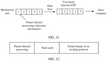
- a mechanical arm (which may also be another device) needs to feed back status information (for example, posture information and power information) in real time to a host computer for display, if a transmission delay of the data packet exceeds a delay threshold, data in the data packet is expired data, and the data packet cannot be sent to the host computer.
- the first indication information may include the packet discard indication information.
- Holographic data, augmented reality (augmented reality, AR) data, or virtual reality (virtual reality, VR) data needs to be transmitted to a server for processing.
- Some data in the holographic/AR/VR data is computing-delay-sensitivity data (which is also referred to as computing-delay-sensitive data), and some data is computing-delay-insensitivity data (which is also referred to as computing-delay-tolerant data).
- the first indication information may include the data type indication information. Alternatively, when corresponding processing needs to be performed on video frames of different types, the first indication information may include the data type indication information.
- the first indication information may include the charging indication information. If statistics or statistics-free processing needs to be performed on the data packet generated by the APP installed on the terminal device, the first indication information may include the statistics indication information. If importance of data in the data packet is higher or lower than importance of data in another data packet, the first indication information may include the priority indication information or the like.
- the first data packet may further carry the delay threshold.
- a value of the delay threshold is random, and is not limited in this embodiment of this application.
- the delay threshold may be 5 milliseconds (ms), 10 ms, or the like.
- the APP of the terminal device generates a data packet A, and the terminal device may add the first indication information to the data packet A, to generate the first data packet.
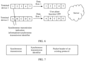
- the terminal device may further add an (allocated) synchronous transmission identifier (ID) to the data packet A, to generate a second data packet, and send the second data packet to an access network element.
- the access network element generates the first data packet based on the second data packet, and sends the first data packet to a first user plane network element.
- the APP of the terminal device generates the data packet A, and the terminal device may add a first field based on the data packet A, to generate the first data packet.
- the first data packet may include the first field, and the first field includes the first indication information.
- the first indication information indicates a data packet processing type and/or a parameter required for data processing, and the first field indicates the first user plane network element to process the first data packet.
- the data packet processing type includes one or more of the following: synchronous transmission, packet discard processing, routing selection, charging or charging-free processing, statistics or statistics-free processing, improving or reducing a priority, improving or reducing QoS, or the like.
- the parameter required for data packet processing includes one or more of the following: a synchronous transmission ID allocated for synchronous transmission, a data type, a null value (null), or the like.
- the first data packet includes a packet granularity control field (namely, the first field) and the data packet A, where the first field may be represented by command, a packet header of the data packet A may use a protocol such as the GPRS tunneling protocol (GPRS tunneling protocol, GTP), or the service data adaptation protocol (service data adaptation protocol, SDAP), the data packet processing type may be represented by action, and the parameter required for data packet processing may be represented by flag.
- GPRS tunneling protocol GPRS tunneling protocol, GTP
- service data adaptation protocol service data adaptation protocol
- the data packet processing type may be represented by action
- the parameter required for data packet processing may be represented by flag.
- the data packet processing type action and the parameter flag are only terms shown in this embodiment of this application, or other terms may be used to describe the data packet processing type and the parameter, to implement similar or same functions.
- the APP of the terminal device expects to implement synchronous transmission
- the data packet processing type in the first field includes synchronous transmission
- the parameter required for data packet processing in the first field includes the synchronous transmission identifier allocated for synchronous transmission.
- a first control plane network element may deliver second configuration information, and the terminal device may receive the second configuration information from the first control plane network element, where the second configuration information includes one or more of the following information: the synchronous transmission indication information, the packet discard indication information, the data type indication information, the charging indication information, the statistics indication information, the priority indication information, or the like.
- the first control plane network element may preconfigure configuration information related to data packet processing to the terminal device.
- the terminal device may select, based on the second configuration information and an actual requirement, specific information included in the first indication information.
- the terminal device may further send a first request message, where the first request message requests to establish or modify a session.
- the first request message may be a PDU session establishment or modification request message, and the PDU session establishment or modification request message requests to establish or modify a PDU session.
- the first request message includes information about the data packet processing type and/or identification information corresponding to a data flow.
- the identification information corresponding to the data flow requests to process a data packet in a data flow of the identification information, and the identification information corresponding to the data flow can be used to uniquely identify the data flow.
- an example in which the identification information corresponding to the data flow is an APP ID is used for description.
- the second configuration information may be sent in a process of establishing a user plane path of the terminal device.
- the first control plane network element may send the second configuration information before the user plane path of the terminal device is established.
- the first control plane network element may further select, based on the information about the data packet processing type, a first user plane network element that has a processing capability required for the data packet processing type. In other words, the first user plane network element selected by the first control plane network element supports the data packet processing type.
- the first control plane network element may further give authorization to perform a requested data packet processing type on the data packet in a data flow of the identification information.
- the first control plane network element may give authorization to perform synchronous transmission on a data packet in an APP1 ID of a terminal device 1, or a second control plane network element (UDM network element) may give authorization to perform the requested data packet processing type on the data packet in a data flow of the identification information.
- UDM network element may give authorization to perform the requested data packet processing type on the data packet in a data flow of the identification information.
- the first control plane network element may further allocate a first synchronous transmission identifier for the terminal device (or the identification information corresponding to the data flow). For example, the first control plane network element allocates the first synchronous transmission identifier based on a synchronous transmission type and/or the identification information corresponding to the data flow.
- the terminal device may further receive the first synchronous transmission identifier, where the first synchronous transmission identifier indicates the first user plane network element to perform synchronous transmission on a data packet that carries a synchronous transmission identifier associated with the first synchronous transmission identifier.
- the second configuration information may further include the first synchronous transmission identifier, or other information may carry the first synchronous transmission identifier.
- the first data packet may further include the first synchronous transmission identifier if the first indication information includes synchronous transmission, the first data packet may further include the first synchronous transmission identifier.
- S302 The terminal device sends the first data packet, and the first user plane network element receives the first data packet.
- the terminal device may send the first data packet to the access network element, and the access network element sends the first data packet to the first user plane network element.
- the access network element may also be referred to as a second user plane network element.
- the terminal device sends the second data packet to the access network element, where the second data packet carries a second synchronous transmission identifier.
- the access network element may sequentially add the synchronous transmission indication information to each second data packet based on a time sequence of receiving each second data packet, to generate the first data packet, and send the generated first data packet to the first user plane network element each time after adding the synchronous transmission indication information.
- the first control plane network element may deliver first configuration information, and the first user plane network element may receive the first configuration information from the first control plane network element, where the first configuration information includes one or more of the following information: the synchronous transmission indication information, the packet discard indication information, the data type indication information, the charging indication information, the statistics indication information, the priority indication information, or the like.
- the first configuration information configures a packet detection rule (packet detection rule, PDR) and/or a forwarding action rule (forwarding action rule, FAR) in the first user plane network element.
- the first user plane network element may perform corresponding processing on the first data packet based on the first indication information. For a specific processing process of the first user plane network element, refer to the following S303.
- the first user plane network element may be selected by the first control plane network element, and the first user plane network element has the processing capability required for the data packet processing type.
- the first control plane network element delivers the first configuration information to the selected first user plane network element.
- the first control plane network element may further send the first synchronous transmission identifier and/or a synchronous transmission precision requirement that are/is allocated for the terminal device.
- the first synchronous transmission identifier indicates the first user plane network element to perform synchronous transmission on the data packet that carries the synchronous transmission identifier associated with the first synchronous transmission identifier.
- the synchronous transmission precision requirement indicates synchronous transmission precision that needs to be achieved in a synchronous transmission process. For example, the synchronous transmission precision requirement is 99%. It is assumed that the terminal device 1 and a terminal device 2 each send 100 data packets. In this case, it indicates that synchronous transmission is implemented (or needs to be implemented) for 99 data packets thereof.
- the first configuration information may further include the first synchronous transmission identifier and/or the synchronous transmission precision requirement, or other information may carry the first synchronous transmission identifier and/or the synchronous transmission precision requirement.
- the first control plane network element may further send the delay threshold.
- the value of the delay threshold is random. This is not limited in this embodiment of this application.
- the first user plane network element processes the first data packet based on the first indication information.
- the first user plane network element may perform differentiated processing on the received data packet based on different information carried in the first indication information.
- the following provides a detailed example for description.
- the first user plane network element may synchronously transmit the first data packet and at least one second data packet.
- the synchronous transmission indication information carried in the at least one second data packet is associated with the synchronous transmission indication information carried in the first data packet.
- the synchronous transmission indication information carried in the at least one second data packet and the synchronous transmission indication information carried in the first data packet are the same or have an association relationship.
- a third synchronous transmission identifier carried in the at least one second data packet and the first synchronous transmission identifier carried in the first data packet are the same, a third synchronous transmission identifier and the first synchronous transmission identifier have an association relationship (for example, stored in a same association table), or a third synchronous transmission identifier and the first synchronous transmission identifier may be mutually converted by using a preset algorithm (obtained by mutually deriving by using a mathematical formula).
- synchronous transmission in this embodiment of this application means that a data packet that needs to be synchronously transmitted is sent in a first time interval.
- the first user plane network element may configure the first time interval for the data packet that needs to be synchronously transmitted for transmission, which may alternatively be implemented by using another scheduling mechanism.
- the first time interval represents any time interval. This is not limited in this embodiment of this application.
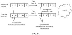
- the first data packet is a data packet in a first data flow
- the second data packet is a data packet in a second data flow. That is, the first data packet and the second data packet belong to different data flows.
- the first user plane network element may implement synchronous transmission of data packets in a plurality of data flows, so that an error in synchronous transmission can be avoided, and a synchronization error between data flows that have a synchronous transmission requirement can be avoided.
- the first user plane network element may discard the first data packet based on the packet discard indication information when network congestion occurs; or after the first data packet is received, the first user plane network element discards the first data packet based on the packet discard indication information when it is identified that transmission duration of the first data packet exceeds the delay threshold.
- the data type indication information may be used to indicate the computing-delay-sensitive data or the computing-delay-tolerant data.
- a user plane network element configured to process the computing-delay-sensitive data and a user plane network element configured to process the computing-delay-tolerant data may be different.
- the user plane network element configured to process the computing-delay-sensitive data is a UPF network element 1
- the user plane network element configured to process the computing-delay-tolerant data is a UPF network element 2.
- the network architecture may further include an uplink classifier (uplink classifier, ULCL), and the ULCL may alternatively be considered as the user plane network element.
- the ULCL may perform data packet routing selection or data packet offloading transmission, transmit a data packet of the computing-delay-sensitive data to the UPF network element 1, and transmit a data packet of the computing-delay-tolerant data to the UPF network element 2.
- the data type indication information indicates a video frame type of the first data packet.
- the video frame type includes one or more of the following: an I-frame, a P-frame, or a B-frame.
- each data packet carries one type of video frame data.
- the first user plane network element may improve QoS guarantee of the first data packet when network congestion occurs; or the first user plane network element may improve QoS guarantee of the first data packet when it is identified that the transmission duration of the first data packet exceeds the delay threshold.
- the first user plane network element may reduce QoS guarantee of the first data packet when network congestion occurs; or the first user plane network element may reduce QoS guarantee of the first data packet when it is identified that the transmission duration of the first data packet exceeds the delay threshold.
- the first user plane network element may execute, for the first data packet, a charging rule indicated by the charging indication information.
- the first user plane network element may perform charging or charging-free on the first data packet based on the charging indication information and the charging rule. For example, if the charging indication information indicates that the first data packet does not need to be charged or is free of charging, the first user plane network element may not perform charging or perform charging-free on the first data packet; or if the charging indication information indicates to perform double charging on the first data packet, the first user plane network element may perform double charging on the first data packet.
- the first user plane network element may execute, for the first data packet, a statistics rule indicated by the statistics indication information.
- the first user plane network element may perform statistics or statistics-free on the first data packet based on the statistics indication information and the statistics rule. For example, if the statistics indication information indicates that the first data packet does not need to be counted or is free of counting, the first user plane network element may not perform statistics or perform statistics-free on the first data packet; or if the statistics indication information indicates to perform double statistics on the first data packet, the first user plane network element may perform double statistics on the first data packet.
- the first user plane network element transmits the first data packet when network congestion occurs; or after the first data packet is received, the first user plane network element improves QoS guarantee of the first data packet when it is identified that the transmission duration of the first data packet exceeds the delay threshold.
- the first user plane network element discards (or does not transmit) the first data packet when network congestion occurs; or after the first data packet is received, the first user plane network element reduces QoS guarantee of the first data packet when it is identified that the transmission duration of the first data packet exceeds the delay threshold.
- the terminal device sends the data packet that carries the first indication information, where the first indication information includes one or more of the synchronous transmission indication information, the packet discard indication information, the data type indication information, the charging indication information, the statistics indication information, or the priority indication information.
- the user plane network element may perform corresponding processing on the received data packet based on the first indication information in the received data packet, so that the user plane network element can perform refined differentiated processing on different data packets at the packet granularity, to ensure to adapt to and meet different user requirements and network conditions.
- a first user plane network element receives a first data packet, where the first data packet carries first indication information.
- the first indication information includes one or more of the following: synchronous transmission indication information, packet discard indication information, data type indication information, charging indication information, statistics indication information, or priority indication information.
- the first user plane network element processes the first data packet based on the first indication information. For the process, refer to the foregoing S303.
- the first indication information includes the synchronous transmission indication information.
- the first user plane network element may synchronously transmit the first data packet and at least one second data packet, where synchronous transmission indication information carried in the at least one second data packet is associated with the synchronous transmission indication information carried in the first data packet.
- the first data packet is a data packet in a first data flow
- the second data packet is a data packet in a second data flow.
- the first indication information includes the packet discard indication information.
- the first user plane network element may discard the first data packet based on the packet discard indication information when network congestion occurs; or after the first data packet is received, discard the first data packet based on the packet discard indication information when it is identified that transmission duration of the first data packet exceeds a delay threshold, where the delay threshold is received by the first user plane network element from a first control plane network element or the first data packet carries the delay threshold.
- the first indication information includes the data type indication information
- the data type indication information indicates a video frame type of the first data packet
- the video frame type includes one or more of the following: an I-frame, a P-frame, or a B-frame.
- Quality of service QoS guarantee provided by the first user plane network element for a data packet whose video frame type is the I-frame is higher than QoS guarantee provided for a data packet whose video frame type is the P-frame or the B-frame.
- the first indication information includes the charging indication information; and when processing the first data packet based on the first indication information, the first user plane network element may execute, for the first data packet, a charging rule indicated by the charging indication information.
- the first indication information includes the statistics indication information; and when processing the first data packet based on the first indication information, the first user plane network element may execute, for the first data packet, a statistics rule indicated by the statistics indication information.
- the first indication information includes the priority indication information, and the priority indication information includes a high priority.
- the first user plane network element may transmit the first data packet when network congestion occurs, or after the first data packet is received, improve QoS guarantee of the first data packet when it is identified that the transmission duration of the first data packet exceeds the delay threshold.
- the first data packet includes a first field
- the first field includes the first indication information
- the first indication information indicates a data packet processing type and/or a parameter required for data processing
- the first field indicates the first user plane network element to process the first data packet.
- the data packet processing type includes one or more of the following: synchronous transmission, packet discard processing, routing selection, charging or charging-free processing, statistics or statistics-free processing, improving or reducing a priority, or improving or reducing QoS.
- the first user plane network element may further receive first configuration information from the first control plane network element, where the first configuration information includes one or more of the following: the synchronous transmission indication information, the packet discard indication information, the data type indication information, the charging indication information, the statistics indication information, or the priority indication information.
- the first user plane network element may process the first data packet based on the first indication information.
- the first configuration information includes the synchronous transmission indication information
- the first user plane network element may further receive a first synchronous transmission identifier and/or a synchronous transmission precision requirement, where the first synchronous transmission identifier indicates the first user plane network element to perform synchronous transmission on a data packet that carries a synchronous transmission identifier associated with the first synchronous transmission identifier.
- the first indication information includes the synchronous transmission indication information
- the first data packet is a data packet generated by an access network element by adding the synchronous transmission indication information to a second data packet
- the second data packet comes from a terminal device or a server
- the second data packet carries a second synchronous transmission identifier
- a terminal device or a server generates a first data packet, where the first data packet carries first indication information.
- the first indication information includes one or more of the following: synchronous transmission indication information, packet discard indication information, data type indication information, charging indication information, statistics indication information, or priority indication information.
- the terminal device or the server sends the first data packet.
- the first indication information includes the packet discard indication information and/or the priority indication information, and the first data packet further carries a delay threshold.
- the terminal device or the server may further receive second configuration information from a first control plane network element, where the second configuration information includes one or more of the following: the synchronous transmission indication information, the packet discard indication information, the data type indication information, the charging indication information, the statistics indication information, or the priority indication information.
- the second configuration information includes the synchronous transmission indication information
- the terminal device or the server may further receive a first synchronous transmission identifier, where the first synchronous transmission identifier indicates the first user plane network element to perform synchronous transmission on a data packet that carries a synchronous transmission identifier associated with the first synchronous transmission identifier.
- the first data packet includes a first field
- the first field includes the first indication information
- the first indication information indicates the data packet processing type and/or a parameter required for data processing
- the first field indicates the first user plane network element to process the first data packet.
- a first control plane network element delivers configuration information, where the configuration information includes one or more of the following: synchronous transmission indication information, packet discard indication information, data type indication information, charging indication information, statistics indication information, or priority indication information.
- the first control plane network element may further receive a first request message, where the first request message requests to establish or modify a session, a first request includes information about a data packet processing type and/or identification information corresponding to a data flow, and the identification information corresponding to the data flow requests to process a data packet in a data flow of the identification information.
- the first control plane network element may further select, based on the information about the data packet processing type, a first user plane network element that has a processing capability required for the data packet processing type.
- the first control plane network element may deliver the configuration information to the first user plane network element.
- the data packet processing type includes one or more of the following: synchronous transmission, packet discard processing, routing selection, charging or charging-free processing, statistics or statistics-free processing, improving or reducing a priority, or improving or reducing QoS.
- the data packet processing type includes synchronous transmission
- the first control plane network element may further allocate a first synchronous transmission identifier based on a synchronous transmission type and the identification information corresponding to the data flow.
- the first control plane network element may further send the first synchronous transmission identifier and/or a synchronous transmission precision requirement.
- the data packet processing type includes packet discard processing
- the first control plane network element may further send a delay threshold.
- the first control plane network element may further give authorization to perform a requested data packet processing type on the data packet in a data flow of the identification information.
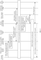
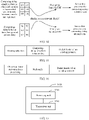
- the user plane network element and the control plane network element may simultaneously support differentiated processing on the data packet. As shown in FIG. 4B , the following process is included.
- An AF network element sends transmission configuration information to the UDM network element.
- the transmission configuration information is related to the data packet processing type. For example, for different data packet processing types, information carried in the transmission configuration information is different.
- the AF network element sends policy configuration information to a PCF network element.
- the policy configuration information is also related to the data packet processing type. For example, for the data packet processing type of synchronous transmission, the policy configuration information indicates the synchronous transmission precision requirement.
- S402 is an optional step.
- the AF network element may not send the policy configuration information to the PCF network element. That is, the AF network element may not perform S402.
- S403 The terminal device sends the first request message, where the first request message requests to establish or modify the session.
- the first request message carries identification information of the APP installed on the terminal device (which is referred to as an application identifier/APP identifier for short below) and the information about the data packet processing type.
- the first request message is a PDU session establishment request message.
- S404 The SMF network element obtains session subscription information from the DUM network element.
- the UDM network element gives authorization, based on the configuration information in S401 and S402, to verify whether the terminal device is allowed to use the APP to perform the requested data packet processing.
- the SMF network element performs session granularity authentication and authorization.
- S405 The SMF network element obtains session policy information from the PCF network element, to implement session policy authorization.
- S406 Complete establishment of a user plane path between the terminal device, a (R)AN, and a UPF network element.
- the establishment of the user plane path may implement establishment of a differentiated path for data packet transmission, and implement differentiated configuration for data packet processing.
- S403 to S406 may be considered as a process in which the control plane network element supports differentiated processing on the data packet.
- S407 The terminal device sends the first data packet to the UPF network element.
- the first data packet carries the first indication information.
- transmission of the first data packet on the differentiated path may be implemented.
- the UPF network element may perform corresponding processing (for example, synchronous transmission, packet discard, statistics or statistics-free, and charging or charging-free) on the first data packet based on the first indication information, to implement differentiated processing at the data packet granularity.
- processing for example, synchronous transmission, packet discard, statistics or statistics-free, and charging or charging-free
- the data packet processing type includes synchronous transmission.
- synchronous transmission is performed on the data packets in the plurality of data flows.
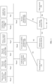
- An embodiment of this application provides a control procedure for synchronous transmission of a plurality of data flows. As shown in FIG. 5A and FIG. 5B , the procedure includes the following process.
- FIG. 5A and FIG. 5B shows synchronous transmission between a terminal device 1 and a terminal device 2.
- a control procedure of the terminal device 1 is mainly used as an example, and a control procedure of the terminal device 2 is similar to the control procedure of the terminal device 1, and repeated parts are not described again.
- S501 An AF network element sends synchronous transmission configuration information to a UDM network element.
- the AF network element may configure, in a subscribed terminal device, an APP of a terminal device that needs to transmit uplink synchronous data.
- the synchronous transmission configuration information indicates that an APP 1 of the terminal device 1 and an APP 2 of the terminal device 2 need to transmit the uplink synchronous data.
- the APP 1 represents identification information of an APP that is in the terminal device 1 and that needs to transmit the uplink synchronous data
- the APP 2 represents identifier information of an APP that is in the terminal device 2 and that needs to transmit the uplink synchronous data.
- the identification information of the APP may be represented by using a triplet, where the triplet includes a destination address, a destination port number, and a protocol type.
- the AF network element sends synchronous precision configuration information to a PCF network element.
- the synchronous precision configuration information indicates a synchronous transmission precision requirement.
- the synchronous transmission precision requirement is not limited in this embodiment of this application.
- the synchronous transmission precision requirement may be 99%.
- S503 The terminal device sends a PDU session establishment request message.
- An AMF network element receives the PDU session establishment request message.
- the PDU session establishment request message carries the APP 1 (to be specific, the identification information of the APP that is in the terminal device 1 and that needs to transmit the uplink synchronous data) and a data packet processing type of synchronous transmission; or the PDU session establishment request message carries the APP 2 and a data packet processing type of synchronous transmission.
- the AMF network element selects an SMF network element, where the SMF network element selected by the AMF network element supports synchronous transmission.
- Whether the SMF network element supports synchronous transmission is determined by a hardware feature of the SMF.
- S505 Establish a PDU session management context between the AMF network element and the (selected) SMF network element.
- the AMF network element sends the APP 1 and the data packet processing type of synchronous transmission to the SMF network element; or the AMF network element sends the APP 2 and the data packet processing type of synchronous transmission to the SMF network element.
- the SMF network element obtains session subscription information from the UDM network element.
- the session subscription information indicates that the APP 1 and the APP 2 are allowed to perform synchronous transmission.
- the UDM network element authorizes and verifies, based on the configuration information in S501 and S502, whether the terminal device 1 is allowed to use the APP 1 to perform synchronous transmission. If authorizing and verifying that the APP 1 may perform synchronous transmission, the UDM sends the indication information "indicating that the APP 1 and the APP 2 are allowed to perform synchronous transmission" to the SMF network element. Alternatively, the UDM network element authorizes and verifies, based on configuration information in S601 and S602, whether the terminal device 2 is allowed to use the APP 2 to perform synchronous transmission. If authorizing and verifying that the APP 1 may perform synchronous transmission, the UDM sends the indication information "indicating that the APP 1 and the APP 2 are allowed to perform synchronous transmission" to the SMF network element.
- the indication information "indicating that the APP 1 and the APP 2 are allowed to perform synchronous transmission” includes identification information of the terminal device 1, the APP 1, identification information of the terminal device 2, the APP 2, and synchronous transmission indication information.
- S507 The SMF network element performs PDU session granularity authentication and authorization.
- the SMF network element selects the PCF network element and a UPF network element, where the PFC network element and the UPF network element that are selected by the SMF network element support synchronous transmission.
- Whether a PFC network element supports synchronous transmission is determined by a hardware feature of the PFC network element, and whether the UPF network element supports synchronous transmission is determined by a hardware feature of the UPF network element.
- the SMF network element obtains session policy information from the PCF network element, to implement session policy authorization.
- the session policy information indicates that a synchronous transmission precision requirement between the APP 1 and the APP 2 is 99%.
- S510 The SMF network element sends an N4 session establishment request to the UPF network element.
- the N4 session establishment request indicates the UPF network element to perform synchronous transmission on a data packet of the APP 1 (or the APP 2).
- the N4 session establishment request includes the APP 1, the synchronous transmission indication information, the synchronous transmission precision requirement, and a synchronous transmission ID allocated by the SMF network element for the APP 1.
- the N4 session establishment request includes the APP 2, the synchronous transmission indication information, the synchronous transmission precision requirement, and a synchronous transmission ID allocated by the SMF network element for the APP 2. Because synchronous transmission is performed between the APP 1 and the APP 2, the synchronous transmission ID allocated for the APP 1 is the same as or associated with the synchronous transmission ID allocated for the APP 2.
- an internet protocol (internet protocol, IP) address of the terminal device 1 or an IP address of the terminal device 2 is already allocated
- the identification information of the APP may be represented by using a quadruplet, and the quadruplet includes the destination address, the destination port number, the protocol type, and an IP address of the terminal device.
- the SMF network element sends a session establishment accept (for example, Namf_Communication_N1N2MessageTransfer) to the AMF network element.
- a session establishment accept for example, Namf_Communication_N1N2MessageTransfer
- the session establishment accept includes the APP 1 (or the APP 2) and the synchronous transmission indication information.
- the AMF network element sends an N2 PDU session request message to a (R)AN.
- the AMF network element notifies the (R)AN to establish a radio bearer.
- the N2 PDU session request message includes a NAS message, and the NAS message includes the APP 1 (or the APP 2) and the synchronous transmission indication information.
- S514 Establish an access network resource between the (R)AN and the terminal device.
- An access network resource establishment message is the NAS message, and the NAS message includes the APP 1 (or the APP 2) and the synchronous transmission indication information.
- S515 Establish a remaining user plane path between the terminal device, the (R)AN, and the UPF network element.
- a data flow 1 generated by the terminal device 1 includes a data packet 1, a data packet 2, a data packet 3, a data packet 4, and a data packet 5, and each data packet includes the synchronous transmission indication information and a synchronous transmission ID.
- the terminal device 1 sequentially sends the data packets in the data flow 1 to the (R)AN, and the (R)AN sequentially sends the data packets in the data flow 1 to the UPF network element.
- a structure of the data packet 1 may be shown in FIG. 7 .
- the data packet processing type includes synchronous transmission, and a parameter required for data packet processing includes the synchronous transmission identifier ID.
- the data packet 1 includes Command:[Action: Synchronize transmission, flag 0x0001].
- a data flow 2 generated by the terminal device 2 includes a data packet A, a data packet B, a data packet C, a data packet D, and a data packet E, and each data packet includes the synchronous transmission indication information and the synchronous transmission ID.
- the terminal device 2 sequentially sends the data packets in the data flow 2 to the (R)AN, and the (R)AN sequentially sends the data packets in the data flow 2 to the UPF network element.
- a structure of the data packet A may also be shown in FIG. 8A and FIG. 8B .
- the data packet processing type includes synchronous transmission, and a parameter required for data packet processing includes the synchronous transmission ID.
- the data packet A includes Command: [Action: Synchronize transmission, flag 0x0001].
- the UPF network element receives the data packets in the data flow 1 and the data packets in the data flow 2.
- the UPF network element may identify, based on the synchronous transmission IDs carried in the data packets, data flows to which the data packets belong that need to be synchronously transmitted.
- the UPF network element may further determine a plurality of data packets that carry a same synchronous transmission ID and that have same (or close) receiving time as data packets that need to be synchronously transmitted, and synchronously transmit the plurality of data packets.
- the UPF network element synchronously transmits the data packet 1 and the data packet A to a server, and synchronously transmits the data packet 2 and the data packet B to the server until all data packets in the data flow 1 and the data flow 2 are synchronously transmitted.
- the UPF network element may perform statistics on a data packet that performs synchronous transmission, and complete corresponding charging work with a user service charging system (online charging system/offline charging system, OCS/OFCS).
- a user service charging system online charging system/offline charging system, OCS/OFCS.
- control procedure for synchronous transmission of the plurality of data flows may alternatively include the following steps.
- S812 The SMF network element sends a session establishment accept (for example, Namf_Communication_N1N2MessageTransfer) to the AMF network element.
- a session establishment accept for example, Namf_Communication_N1N2MessageTransfer
- the session establishment accept includes the APP 1 (or the APP 2), the synchronous transmission indication information, and a synchronous transmission ID.
- the AMF network element sends an N2 PDU session request message to a (R)AN.
- the AMF network element notifies the (R)AN to establish a radio bearer.
- the N2 PDU session request message includes a NAS message, and the NAS message includes the APP 1 (or the APP 2), the synchronous transmission indication information, and the synchronous transmission ID.
- S814 Establish an access network resource between the (R)AN and the terminal device.
- An access network resource establishment message is the NAS message, and the NAS message includes the APP 1 (or the APP 2), the synchronous transmission indication information, and the synchronous transmission ID.
- a data flow 1 generated by the terminal device 1 includes a data packet 1, a data packet 2, a data packet 3, a data packet 4, and a data packet 5, and each data packet includes the synchronous transmission ID.
- the terminal device 1 sequentially sends the data packets in the data flow 1 to the (R)AN.
- a data flow 2 generated by the terminal device 2 includes a data packet A, a data packet B, a data packet C, a data packet D, and a data packet E, and each data packet includes the synchronous transmission ID.
- the terminal device 2 sequentially sends the data packets in the data flow 2 to the (R)AN.
- the (R)AN receives the data packet, and may determine, based on a plurality of data packets that carry a same synchronous transmission ID and that have same (or close) receiving time, that the plurality of data packets are data packets that need to be synchronously transmitted. Then, the (R)AN sequentially adds the synchronous transmission indication information to the received data packets (for example, adds information included in command to the data packets) based on a time sequence of receiving the data packets, and sends, to the UPF network element each time after adding the synchronous transmission indication information to the data packets, data packets that carry the "synchronous transmission indication information". For an operation of the UPF network element, refer to FIG. 5A and FIG. 5B . Details are not described herein again.
- the data packet processing type includes (timeout-based) packet discard processing, to be specific, discards a packet whose transmission duration exceeds the delay threshold in the data flow.
- An embodiment of this application proposes a timeout-based data packet discard control procedure. As shown in FIG. 10A and FIG. 10B , the procedure includes the following process.
- S1001 An AF network element sends transmission configuration information to a UDM network element.
- the AF network element may configure, in a subscribed terminal device, an APP of a terminal device that is allowed to perform timeout-based packet discard processing, for example, may be applied to area of interest (area of interest, AoI) processing in a game scenario.
- the transmission configuration information indicates that an APP 1 of a terminal device 1 is allowed to perform timeout-based packet discard processing, and a delay threshold is 10 ms.
- S1002 The terminal device sends a PDU session establishment request message.
- An AMF network element receives the PDU session establishment request message.
- the PDU session establishment request message carries the APP 1 (to be specific, identification information of an APP that is in the terminal device 1 and that needs to transmit uplink synchronous data) and a data packet processing type of (timeout-based) packet discard processing; or the PDU session establishment request message carries an APP 2 and a data packet processing type of (timeout-based) packet discard processing.
- the AMF network element selects an SMF network element, where the SMF network element selected by the AMF network element supports (timeout-based) packet discard processing.
- S1004 Establish a PDU session management context between the AMF network element and the SMF network element.
- the AMF network element sends the APP 1 and the data packet processing type of (timeout-based) packet discard processing to the SMF network element; or the AMF network element sends the APP 2 and the data packet processing type of (timeout-based) packet discard processing to the SMF network element.
- the SMF network element obtains session subscription information from the UDM network element.
- the session subscription information indicates that the APP 1 may perform (timeout-based) packet discard processing.
- the UDM network element authorizes and verifies, based on the configuration information in S1001, whether the terminal device 1 is allowed to use the APP 1 to perform (timeout-based) packet discard processing. If authorizing and verifying that the APP 1 may perform (timeout-based) packet discard processing, the UDM sends indication information "indicating that the APP 1 is allowed to perform (timeout-based) packet discard processing" to the SMF network element.
- the indication information "indicating that the APP 1 is allowed to perform (timeout-based) packet discard processing” includes identification information of the terminal device 1, the APP 1, (timeout-based) packet discard processing indication information, and the delay threshold.
- S 1006 The SMF network element performs PDU session granularity authentication and authorization.
- the SMF network element selects a PCF network element and a UPF network element, where a PFC network element and the UPF network element that are selected by the SMF network element support (timeout-based) packet discard processing.
- S 1008 The SMF network element obtains session policy information from the PCF network element, to implement session policy authorization.
- the SMF network element sends an N4 session establishment request to the UPF network element.
- the N4 session establishment request indicates the UPF network element to perform (timeout-based) packet discard processing on a data packet of the APP 1.
- the N4 session establishment request includes the APP 1, the (timeout-based) data packet discard indication information, and the delay threshold.
- the identification information of the APP may be represented by using a quadruplet, and the quadruplet includes a destination address, a destination port number, a protocol type, and an IP address of the terminal device.
- S1011 The SMF network element sends a session establishment accept (for example, Namf_Communication_N1N2MessageTransfer) to the AMF network element.
- a session establishment accept for example, Namf_Communication_N1N2MessageTransfer
- the session establishment accept includes the APP 1 and the (timeout-based) packet discard indication information.
- the AMF network element sends an N2 PDU session request message to a (R)AN.
- the AMF network element notifies the (R)AN to establish a radio bearer.
- the N2 PDU session request message includes a NAS message, and the NAS message includes the APP 1 and the (timeout-based) packet discard indication information.
- S1013 Establish an access network resource between the (R)AN and the terminal device.
- An access network resource establishment message is the NAS message, and the NAS message includes the APP 1 and the (timeout-based) packet discard indication information.
- a (timeout-based) packet discard processing request of the terminal device succeeds.
- S1014 Establish a remaining user plane path between the terminal device, the (R)AN, and the UPF network element.
- a data flow generated by a mechanical arm includes a data packet 1, a data packet 2, a data packet 3, a data packet 4, and a data packet 5, and each data packet includes the (timeout-based) packet discard indication information.
- the mechanical arm sequentially sends the data packets in the data flow to the (R)AN, and the (R)AN sequentially sends the data packets in the data flow to the UPF network element.
- a structure of the data packet 1 may be shown in FIG. 12 .
- the data packet processing type includes (timeout-based) packet discard processing, and a parameter required for data packet processing includes null.
- the data packet 1 includes Command: [Action: Drop].
- the UPF network element adds a timestamp at which the data packet is received to the data packet, and performs statistics on transmission duration of the data packet. If the transmission duration of the data packet exceeds the delay threshold, the UPF performs packet discard processing on the data packet.
- the UPF network element may further send the data packet to a host computer.
- the UPF may perform timeout-based packet discard processing only on a data packet that carries Command (to be specific, indicating the data packet processing type of packet discard processing).
- a data packet that carries Command to be specific, indicating the data packet processing type of packet discard processing.
- real-time posture data of the mechanical arm has the (timeout-based) packet discard requirement, but other data (for example, temperature information or a power status of the mechanical arm) does not require strong real-time performance. Therefore, this type of data may not require (timeout-based) packet discard processing.
- routing selection (which may also be referred to as differentiated routing or offloading processing)
- an embodiment of this application proposes a control procedure of routing selection. As shown in FIG. 13A and FIG. 13B , the following process is included.
- An AF network element sends transmission configuration information to a UDM network element.
- the AF network element may configure, in a subscribed terminal device, an APP of a terminal device that is allowed to perform routing selection.
- the transmission configuration information indicates that an APP 1 of a terminal device 1 is allowed to perform routing selection.
- S1302 The terminal device sends a PDU session establishment request message.
- An AMF network element receives the PDU session establishment request message.
- the PDU session establishment request message carries the APP 1 and a data packet processing type of routing processing.
- the AMF network element selects an SMF network element, where the SMF network element selected by the AMF network element supports routing selection.
- Whether the SMF network element supports routing selection is determined by a hardware feature of the SMF.
- S1304 Establish a PDU session management context between the AMF network element and the SMF network element.
- the AMF network element sends the APP 1 and the data packet processing type of routing selection to the SMF network element.
- the SMF network element obtains session subscription information from the UDM network element.
- the session subscription information indicates that the APP 1 is allowed to perform routing selection.
- the UDM network element authorizes and verifies, based on the configuration information in S1301, whether the terminal device 1 is allowed to use the APP 1 to perform routing selection. If authorizing and verifying that the APP 1 may perform routing selection, the UDM sends indication information "indicating that the APP 1 is allowed to perform routing selection" to the SMF network element.
- S 1306 The SMF network element performs PDU session granularity authentication and authorization.
- the SMF network element selects a PCF network element and a UPF network element, where the PFC network element and the UPF network element that are selected by the SMF network element support routing selection.
- Whether a PFC network element supports routing selection is determined by a hardware feature of the PFC network element, and whether the UPF network element supports routing selection is determined by a hardware feature of the UPF network element.
- S 1308 The SMF network element obtains session policy information from the PCF network element, to implement session policy authorization.
- S1309 The SMF network element sends an N4 session establishment request to the UPF network element.
- the N4 session establishment request indicates the UPF network element to perform routing selection on a data packet of the APP 1.
- S1311 The SMF network element sends a session establishment accept (for example, Namf_Communication_N1N2MessageTransfer) to the AMF network element.
- a session establishment accept for example, Namf_Communication_N1N2MessageTransfer
- the AMF network element sends an N2 PDU session request message to a (R)AN.
- the AMF network element notifies the (R)AN to establish a radio bearer.
- the N2 PDU session request message includes a NAS message, and the NAS message includes the APP 1 and the routing selection indication information.
- S1313 Establish an access network resource between the (R)AN and the terminal device.
- An access network resource establishment message is the NAS message, and the NAS message includes the APP 1 and the routing selection indication information.
- S1314 The SMF network element sends an N4 session establishment request message to a ULCL.
- an AMF notifies the ULCL of a traffic forwarding rule.
- the N4 session establishment request message includes the APP 1, indication information about computing-delay-sensitive data, and corresponding path indication information; and/or the N4 session establishment request message includes the APP 1, indication information about computing-delay-tolerant data, and corresponding path indication information.
- the corresponding path indication information may be ULCL path indication information or PDU session anchor (PDU session anchor, PSA) path indication information.
- S1316 The SMF network element updates uplink and downlink data transmission paths of a PSA 1.
- the PSA 1 (or an edge computing node connected to the PSA 1) is configured to process the computing-delay-tolerant data.
- S1317 The SMF network element updates uplink and downlink data transmission paths of a PSA 2.
- the PSA 2 (or an edge computing node connected to the PSA 2) is configured to process the computing-delay-sensitive data.
- the PSA 1 sends downlink data to the ULCL, and the ULCL sends the downlink data to the terminal device; and/or the PSA 2 sends downlink data to the ULCL, and the ULCL sends the downlink data to the terminal device.
- S1318 is an optional step.
- the SMF network element updates an uplink data transmission path of the (R)AN.
- the terminal device sends a data packet of a "computing-delay-tolerant data" type to the ULCL, and the ULCL sends the data packet to the PSA 1; and/or the terminal device sends a data packet of a "computing-delay-tolerant data” type to the ULCL, and the ULCL sends the data packet to the PSA 2.
- an offloading function of the ULCL may be used to perform routing selection on different data packets in one data flow, so that a mobile edge computing (mobile edge computing, MEC) node connected to an offloaded PSA 2 processes the computing-delay-sensitive data, and an MEC node that is connected to an offloaded PSA 1 processes the computing-delay-tolerant data.
- MEC mobile edge computing
- a data flow generated by the terminal device 1 includes a data packet D1, a data packet D2, a data packet D3, a data packet D4, a data packet D5, and a data packet D6 of the computing-delay-sensitive data type.
- the computing-delay-sensitive data may be related information about synchronous transmission of a tactile and a picture.
- the terminal device 1 sends, by using a computing-delay-sensitive data transmission path, a data packet in the data flow to an MEC node connected to the UPF, where the MEC node is a server configured to process the computing-delay-sensitive data.
- a structure of the data packet may be shown in FIG. 15 .
- the data packet processing type includes routing selection, and a parameter required for data packet processing includes the computing-delay-sensitive data or the computing-delay-tolerant data.
- the data flow generated by the terminal device 1 includes a data packet S1, a data packet S2, a data packet S3, a data packet S4, a data packet S5, and a data packet S6 of the computing-delay-tolerant data type.
- the computing-delay-tolerant data may be related information about background picture data.
- the terminal device 1 sends, by using a computing-delay-tolerant data transmission path, a data packet in the data flow to an MEC node connected to the UPF, where the MEC node is a server configured to process the computing-delay-tolerant data.
- timeout-based packet discard shown in FIG. 10A and FIG. 10B may alternatively be replaced with another operation, for example, improving or reducing QoS of the data packet, or improving or reducing a priority of the data packet. That is, the control procedure shown in FIG. 10A and FIG. 10B is also applicable to a data packet processing type of improving or reducing the priority, or improving or reducing QoS.
- the UPF network element For example, if transmission duration of a received data packet exceeds the delay threshold, the UPF network element increases a transmission priority of the data packet, or improves QoS of transmission of the data packet. If network congestion occurs, the UPF network element may improve a transmission priority of the received data packet. In other words, the UPF preferably transmits the data packet.
- the data packet sent by the terminal device may carry data type indication information, and the data type indication information indicates that a video frame type of the data packet is an I-frame, a P-frame, or a B-frame
- the data packet may not carry information included in command.
- QoS guarantee provided by the UPF network element for a data packet of the I-frame is higher than QoS guarantee provided for a data packet of the P-frame or the B-frame. If network congestion occurs, the UPF network element may reserve the data packet of the I-frame, and discard the data packet of the P-frame or the B-frame.
- (timeout-based) packet discard shown in FIG. 10A and FIG. 10B may be replaced with another operation, for example, statistics or statistics-free processing, or charging or charging-free processing. That is, the control procedure shown in FIG. 10A and FIG. 10B is also applicable to statistics or statistics-free processing, or charging or charging-free processing. For example, if the received data packet carries "statistics", the UPF network element may perform statistics on the data packet (where a statistics rule may be agreed upon in advance or separately indicated); and if the received data packet carries "statistics-free", the UPF network element may not perform statistics on the data packet.
- the UPF network element may perform charging on the data packet (where a charging rule may be agreed upon in advance or separately indicated); and if the received data packet carries "charging-free", the UPF network element may not perform charging on the data packet.
- a structure of the data packet may be shown in FIG. 16 .
- the data packet processing type includes (free of) charging/(free of) statistics processing, and a parameter required for data packet processing includes null.
- the communication apparatus 1700 includes a processing unit 1701 and a transceiver unit 1702.
- the apparatus 1700 may be configured to implement the method described in the foregoing method embodiments applied to the user plane network element, the terminal device, or the control plane network element.
- the apparatus 1700 is applied to a user plane network element.
- the transceiver unit 1702 is configured to receive a first data packet, where the first data packet carries first indication information.
- the processing unit 1701 is configured to process the first data packet based on the first indication information.
- the first indication information includes one or more of the following: synchronous transmission indication information, packet discard indication information, data type indication information, charging indication information, statistics indication information, or priority indication information.
- the processing unit 1701 when the first indication information includes the synchronous transmission indication information, is specifically configured to synchronously transmit the first data packet and at least one second data packet by using the transceiver unit 1702, where synchronous transmission indication information carried in the at least one second data packet is associated with the synchronous transmission indication information carried in the first data packet.
- the processing unit 1701 when the first indication information includes the packet discard indication information, is specifically configured to discard the first data packet based on the packet discard indication information when network congestion occurs; or after the first data packet is received, discard the first data packet based on the packet discard indication information when it is identified that transmission duration of the first data packet exceeds a delay threshold, where the delay threshold is received by a first user plane network element from a first control plane network element or the first data packet carries the delay threshold.
- the first indication information includes the data type indication information
- the data type indication information indicates a video frame type of the first data packet
- the video frame type includes one or more of the following: an I-frame, a P-frame, or a B-frame.
- Quality of service QoS guarantee provided by the first user plane network element for a data packet whose video frame type is the I-frame is higher than QoS guarantee provided for a data packet whose video frame type is the P-frame or the B-frame.
- the processing unit 1701 when the first indication information includes the charging indication information, the processing unit 1701 is specifically configured to execute, for the first data packet, a charging rule indicated by the charging indication information.
- the processing unit 1701 when the first indication information includes the statistics indication information, the processing unit 1701 is specifically configured to execute, for the first data packet, a statistics rule indicated by the statistics indication information.
- the processing unit 1701 is specifically configured to: transmit the first data packet by using the transceiver unit 1702 when network congestion occurs; or after the first data packet is received, improve QoS guarantee of the first data packet when it is identified that the transmission duration of the first data packet exceeds the delay threshold.
- the first data packet includes a first field
- the first field includes the first indication information
- the first indication information indicates a data packet processing type and/or a parameter required for data processing
- the first field indicates the first user plane network element to process the first data packet.
- the transceiver unit 1702 is further configured to: before the processing the first data packet based on the first indication information, receive first configuration information from the first control plane network element, where the first configuration information includes one or more of the following: the synchronous transmission indication information, the packet discard indication information, the data type indication information, the charging indication information, the statistics indication information, or the priority indication information.
- the processing unit 1701 is specifically configured to: if a data processing type indicated by the first indication information is associated with the data processing type indicated by the first configuration information, process the first data packet based on the first indication information.
- the first configuration information includes the synchronous transmission indication information
- the transceiver unit 1702 is further configured to receive a first synchronous transmission identifier and/or a synchronous transmission precision requirement, where the first synchronous transmission identifier indicates the first user plane network element to perform synchronous transmission on a data packet that carries a synchronous transmission identifier associated with the first synchronous transmission identifier.
- the apparatus 1700 is used in a terminal device.
- the processing unit 1701 is configured to generate a first data packet, where the first data packet carries first indication information.
- the transceiver unit 1702 is configured to send the first data packet.
- the first indication information includes one or more of the following: synchronous transmission indication information, packet discard indication information, data type indication information, charging indication information, statistics indication information, or priority indication information.
- the transceiver unit 1702 is further configured to: before the generating a first data packet, receive second configuration information from a first control plane network element, where the second configuration information includes one or more of the following: synchronous transmission indication information, packet discard indication information, data type indication information, charging indication information, statistics indication information, or priority indication information.
- the transceiver unit 1702 is further configured to send a first request message, where the first request message requests to establish a session, the first request message includes information about a data packet processing type and/or identification information corresponding to a data flow, and the identification information corresponding to the data flow requests to process a data packet in a data flow of the identification information.
- the second configuration information includes the synchronous transmission indication information
- the transceiver unit 1702 is further configured to receive a first synchronous transmission identifier, where the first synchronous transmission identifier indicates a first user plane network element to perform synchronous transmission on a data packet that carries a synchronous transmission identifier associated with the first synchronous transmission identifier.
- the first data packet includes a first field
- the first field includes the first indication information
- the first indication information indicates the data packet processing type and/or a parameter required for data processing
- the first field indicates the first user plane network element to process the first data packet.
- the apparatus 1700 is applied to a control plane network element.
- the processing unit 1701 is configured to deliver configuration information by using the transceiver unit 1702, where the configuration information includes one or more of the following: synchronous transmission indication information, packet discard indication information, data type indication information, charging indication information, statistics indication information, or priority indication information.
- the transceiver unit 1702 is further configured to: before the delivering configuration information, receive a first request message, where the first request message requests to establish a session, a first request includes information about a data packet processing type and/or identification information corresponding to a data flow, and the identification information corresponding to the data flow requests to process a data packet in a data flow of the identification information.
- the processing unit 1701 is configured to select, based on information about the data packet processing type, a first user plane network element that has a processing capability required for the data packet processing type.
- the transceiver unit 1702 is specifically configured to deliver the configuration information to the first user plane network element.
- the data packet processing type includes one or more of the following: synchronous transmission, packet discard processing, routing selection, charging or charging-free processing, statistics or statistics-free processing, improving or reducing a priority, or improving or reducing QoS.
- the data packet processing type includes synchronous transmission
- the processing unit 1701 is further configured to allocate a first synchronous transmission identifier based on a synchronous transmission type and the identification information corresponding to the data flow.
- the transceiver unit 1702 is further configured to send the first synchronous transmission identifier and/or a synchronous transmission precision requirement.
- the data packet processing type includes packet discard processing
- the transceiver unit 1702 is further configured to send a delay threshold.
- the processing unit 1701 is further configured to: before the delivering configuration information, authorize to perform a requested data packet processing type on the data packet in the data flow of the identification information.
- division into modules is an example, and is only a logical function division. During actual implementation, there may be another division manner.
- functional units in embodiments of this application may be integrated into one processing unit, or may exist alone physically, or two or more units are integrated into one unit.
- the integrated unit may be implemented in a form of hardware, or may be implemented in a form of a software functional unit.
- the integrated unit When the integrated unit is implemented in the form of the software functional unit and sold or used as an independent product, the integrated unit may be stored in a computer-readable storage medium. Based on such an understanding, the technical solutions of this application essentially, or the part contributing to the conventional technology, or all or some of the technical solutions may be implemented in a form of a software product.
- the computer software product is stored in a storage medium, and includes several instructions for instructing a computer device (which may be a personal computer, a server, a network device, or the like) or a processor (processor) to perform all or some of the steps of the methods described in embodiments of this application.
- the foregoing storage medium includes any medium that can store program code, such as a USB flash drive, a removable hard disk, a read-only memory (read-only memory, ROM), a random access memory (random access memory, RAM), a magnetic disk, or an optical disc.
- program code such as a USB flash drive, a removable hard disk, a read-only memory (read-only memory, ROM), a random access memory (random access memory, RAM), a magnetic disk, or an optical disc.
- an embodiment of this application further provides a schematic diagram of a structure of an update apparatus 1800.
- the apparatus 1800 may be configured to implement the method described in the foregoing method embodiments applied to the user plane network element, the terminal device, or the control plane network element. For details, refer to the descriptions in the foregoing method embodiments.
- the apparatus 1800 may be located in a user plane network element, a terminal device, or a control plane network element, or may be a user plane network element, a terminal device, or a control plane network element.
- the apparatus 1800 includes one or more processors 1801.
- the processor 1801 may be a general purpose processor, a dedicated processor, or the like.
- the processor may be a baseband processor or a central processing unit.
- the baseband processor may be configured to process a communication protocol and communication data.
- the central processing unit may be configured to: control a communication apparatus (for example, a base station, a terminal, or a chip), execute a software program, and process data of the software program.
- the communication apparatus may include a transceiver unit, configured to input (receive) and output (send) a signal.
- the transceiver unit may be a transceiver or a radio frequency chip.
- the apparatus 1800 includes one or more processors 1801.
- the one or more processors 1801 may implement the method of the user plane network element, the terminal device, or the control plane network element in the foregoing embodiments.
- processor 1801 may further implement another function in addition to the method in the foregoing embodiments.
- the processor 1801 may execute instructions, so that the apparatus 1800 performs the method described in the foregoing method embodiments. All or some of the instructions, for example, instructions 1803, may be stored in the processor, or all or some of the instructions, for example, instructions 1804, may be stored in a memory 1802 coupled to the processor. Alternatively, the apparatus 1800 may be enabled, by using both the instructions 1803 and the instructions 1804, to perform the method described in the foregoing method embodiments.
- the communication apparatus 1800 may alternatively include a circuit, and the circuit may implement a function of the user plane network element, the terminal device, or the control plane network element in the foregoing method embodiments.
- the apparatus 1800 may include one or more memories 1802.
- the memory stores instructions 1804, and the instructions may be run on the processor, the apparatus 1800 is enabled to perform the method described in the foregoing method embodiments.
- the memory may further store data.
- the processor may alternatively store instructions and/or data.
- the one or more memories 1802 may store the correspondence described in the foregoing embodiments, or the related parameter or table in the foregoing embodiments.
- the processor and the memory may be separately disposed, or may be integrated together.
- the apparatus 1800 may further include a transceiver 1805 and an antenna 1806.
- the processor 1801 may be referred to as a processing unit, and controls the apparatus (a terminal or a base station).
- the transceiver 1805 may be referred to as a transceiver, a transceiver circuit, the transceiver unit, or the like, and is configured to implement a transceiver function of the apparatus by using the antenna 1806.
- the processor in this embodiment of this application may be an integrated circuit chip, and has a signal processing capability.
- the steps in the foregoing method embodiments may be completed by using a hardware integrated logic circuit in the processor or instructions in a form of software.
- the foregoing processor may be a general purpose processor, a digital signal processor (digital signal processor, DSP), an application-specific integrated circuit (application specific integrated circuit, ASIC), a field programmable gate array (field programmable gate array, FPGA) or another programmable logic device, a discrete gate or transistor logic device, or a discrete hardware component. It may implement or perform the methods, the steps, and logical block diagrams that are disclosed in embodiments of this application.
- the general-purpose processor may be a microprocessor, or the processor may be any conventional processor or the like. Steps of the methods disclosed with reference to embodiments of this application may be directly executed and accomplished by a hardware decoding processor, or may be executed and accomplished by using a combination of hardware and software modules in the decoding processor.
- a software module may be located in a mature storage medium in the art, such as a random access memory, a flash memory, a read-only memory, a programmable read-only memory, an electrically erasable programmable memory, or a register. The storage medium is located in the memory, and a processor reads information in the memory and completes the steps in the foregoing methods in combination with hardware of the processor.
- the memory in this embodiment of this application may be a volatile memory or a nonvolatile memory, or may include a volatile memory and a nonvolatile memory.
- the nonvolatile memory may be a read-only memory (read-only memory, ROM), a programmable read-only memory (programmable ROM, PROM), an erasable programmable read-only memory (erasable PROM, EPROM), an electrically erasable programmable read-only memory (electrically EPROM, EEPROM), or a flash memory.
- the volatile memory may be a random access memory (random access memory, RAM), used as an external cache.
- RAMs may be used, for example, a static random access memory (static RAM, SRAM), a dynamic random access memory (dynamic RAM, DRAM), a synchronous dynamic random access memory (synchronous DRAM, SDRAM), a double data rate synchronous dynamic random access memory (double data rate SDRAM, DDR SDRAM), an enhanced synchronous dynamic random access memory (enhanced SDRAM, ESDRAM), a synchlink dynamic random access memory (synchlink DRAM, SLDRAM), and a direct rambus dynamic random access memory (direct rambus RAM, DR RAM).
- static random access memory static random access memory
- DRAM dynamic random access memory
- DRAM dynamic random access memory
- SDRAM synchronous dynamic random access memory
- double data rate SDRAM double data rate SDRAM
- DDR SDRAM double data rate SDRAM
- ESDRAM enhanced synchronous dynamic random access memory
- synchlink dynamic random access memory synchlink dynamic random access memory
- direct rambus RAM direct rambus RAM
- An embodiment of this application further provides a computer-readable medium.
- the computer-readable medium stores a computer program.
- the computer program is executed by a computer, the communication method according to any one of the method embodiments applied to the user plane network element, the terminal device, or the control plane network element is implemented.
- An embodiment of this application further provides a computer program product.
- the computer program product is executed by a computer, the communication method according to any one of the method embodiments applied to the user plane network element, the terminal device, or the control plane network element is implemented.
- An embodiment of this application further provides a communication system.
- the communication system includes the user plane network element and the terminal device that perform the foregoing communication methods, and may further include the control plane network element.
- All or some of the foregoing embodiments may be implemented by using software, hardware, firmware, or any combination thereof.
- the software is used to implement the foregoing embodiments, all or some of the foregoing embodiments may be implemented in a form of a computer program product.
- the computer program product includes one or more computer instructions. When the computer instructions are loaded and executed on the computer, the procedure or functions according to embodiments of this application are all or partially generated.
- the computer may be a general-purpose computer, a dedicated computer, a computer network, or other programmable apparatuses.
- the computer instructions may be stored in a computer-readable storage medium or may be transmitted from a computer-readable storage medium to another computer-readable storage medium.
- the computer instructions may be transmitted from a website, computer, server, or data center to another website, computer, server, or data center in a wired (for example, a coaxial cable, an optical fiber, or a digital subscriber line (digital subscriber line, DSL)), or wireless (for example, infrared, radio, or microwave) manner.
- the computer-readable storage medium may be any usable medium accessible by the computer, or a data storage device, for example, a server or a data center, integrating one or more usable media.
- the usable medium may be a magnetic medium (for example, a floppy disk, a hard disk, or a magnetic tape), an optical medium (for example, a high-density digital video disc (digital video disc, DVD)), a semiconductor medium (for example, a solid-state drive (solid state drive, SSD)), or the like.
- a magnetic medium for example, a floppy disk, a hard disk, or a magnetic tape
- an optical medium for example, a high-density digital video disc (digital video disc, DVD)
- a semiconductor medium for example, a solid-state drive (solid state drive, SSD)
- An embodiment of this application further provides a processing apparatus, including a processor and an interface.
- the processor is configured to perform the communication method according to any one of the method embodiments applied to the user plane network element, the terminal device, or the control plane network element.
- the processing apparatus may be a chip.
- the processor may be implemented by hardware, or may be implemented by software.
- the processor may be a logic circuit, an integrated circuit, or the like.
- the processor may be a general-purpose processor.
- the general-purpose processor is implemented by reading software code stored in a memory.
- the memory may be integrated into the processor, or may be located outside the processor and exist independently.
- the disclosed system, apparatus, and method may be implemented in other manners.
- the described apparatus embodiment is only an example.
- division into the units is only logical function division and may be other division in actual implementation.
- a plurality of units or components may be combined or integrated into another system, or some features may be ignored or not performed.
- the displayed or discussed mutual couplings or direct couplings or communication connections may be implemented through some interfaces, indirect couplings or communication connections between the apparatuses or units, or electrical connections, mechanical connections, or connections in other forms.
- the units described as separate parts may or may not be physically separate, and parts displayed as units may or may not be physical units, in other words, may be located in one position, or may be distributed on a plurality of network units. Some or all of the units may be selected according to actual requirements to achieve the objectives of the solutions of embodiments in this application.
- function units in embodiments of this application may be integrated into one processing unit, each of the units may exist alone physically, or two or more units may be integrated into one unit.
- the integrated unit may be implemented in a form of hardware, or may be implemented in a form of a software functional unit.
- the computer-readable medium includes a computer storage medium and a communication medium, where the communication medium includes any medium that enables a computer program to be transmitted from one place to another.
- the storage medium may be any available medium accessible to a computer.
- the computer-readable medium may include a RAM, a ROM, an EEPROM, a CD-ROM, or another optical disc storage or disk storage medium, another magnetic storage device, or any other medium that can carry or store expected program code in a form of an instruction or a data structure and can be accessed by a computer.
- any connection may be properly defined as a computer-readable medium.
- the software is transmitted from a website, a server, or another remote source by using a coaxial cable, an optical fiber/cable, a twisted pair, a digital subscriber line (DSL), or wireless technologies such as infrared ray, radio and microwave
- a coaxial cable, optical fiber/cable, twisted pair, DSL, or wireless technologies such as infrared ray, radio, and microwave
- the coaxial cable, optical fiber/cable, twisted pair, DSL, or wireless technologies such as infrared ray, radio, and microwave are included in fixation of a medium to which they belong.
- a disk (Disk) and a disc (disc) used in this application include a compact disc (CD), a laser disc, an optical disc, a digital versatile disc (DVD), a floppy disk, and a Blu-ray disc, where the disk generally copies data in a magnetic manner, and the disc copies data optically in a laser manner.
- CD compact disc
- DVD digital versatile disc
- floppy disk a compact disc
- Blu-ray disc where the disk generally copies data in a magnetic manner, and the disc copies data optically in a laser manner.
Landscapes
- Engineering & Computer Science (AREA)
- Computer Networks & Wireless Communication (AREA)
- Signal Processing (AREA)
- Mobile Radio Communication Systems (AREA)
- Data Exchanges In Wide-Area Networks (AREA)
Applications Claiming Priority (1)
| Application Number | Priority Date | Filing Date | Title |
|---|---|---|---|
| PCT/CN2020/086515 WO2021212439A1 (fr) | 2020-04-23 | 2020-04-23 | Procédé et appareil de communication |
Publications (2)
| Publication Number | Publication Date |
|---|---|
| EP4132085A1 true EP4132085A1 (fr) | 2023-02-08 |
| EP4132085A4 EP4132085A4 (fr) | 2023-05-24 |
Family
ID=78270847
Family Applications (1)
| Application Number | Title | Priority Date | Filing Date |
|---|---|---|---|
| EP20932636.2A Pending EP4132085A4 (fr) | 2020-04-23 | 2020-04-23 | Procédé et appareil de communication |
Country Status (5)
| Country | Link |
|---|---|
| US (1) | US12143305B2 (fr) |
| EP (1) | EP4132085A4 (fr) |
| JP (1) | JP2023522447A (fr) |
| CN (1) | CN115428516B (fr) |
| WO (1) | WO2021212439A1 (fr) |
Families Citing this family (15)
| Publication number | Priority date | Publication date | Assignee | Title |
|---|---|---|---|---|
| CN113873582B (zh) * | 2020-06-30 | 2023-03-28 | 华为技术有限公司 | 一种移动边缘计算处理方法以及相关设备 |
| WO2023147707A1 (fr) * | 2022-02-07 | 2023-08-10 | Oppo广东移动通信有限公司 | Procédés de communication, dispositifs de réseau d'accès, éléments de cœur de réseau et équipements terminaux |
| CN117014955A (zh) * | 2022-04-27 | 2023-11-07 | 维沃移动通信有限公司 | 数据处理方法及装置 |
| WO2024055332A1 (fr) * | 2022-09-16 | 2024-03-21 | 北京小米移动软件有限公司 | Appareil et procédé de traitement d'informations, dispositif de communication et support de stockage |
| WO2024055334A1 (fr) * | 2022-09-16 | 2024-03-21 | 北京小米移动软件有限公司 | Procédé et appareil de traitement pour perte de paquets, et dispositif de communication et support d'enregistrement |
| CN118316804A (zh) * | 2023-01-09 | 2024-07-09 | 中国移动通信有限公司研究院 | 信息处理方法、装置、网络设备及存储介质 |
| CN118713783A (zh) * | 2023-03-27 | 2024-09-27 | 华为技术有限公司 | 通信方法、设备、芯片、存储介质和程序产品 |
| US12506911B2 (en) * | 2023-05-11 | 2025-12-23 | Cisco Technology, Inc. | Quality of service enhancements for video and extended reality applications over wireless networks |
| WO2024113907A1 (fr) * | 2023-07-25 | 2024-06-06 | Lenovo (Beijing) Limited | Procédé et appareil de prise en charge de transmissions de synchronisation |
| WO2025039160A1 (fr) * | 2023-08-21 | 2025-02-27 | Oppo广东移动通信有限公司 | Procédé de communication sans fil, et dispositif de communication |
| CN116887009B (zh) * | 2023-09-06 | 2023-12-12 | 湖南智警公共安全技术研究院有限公司 | 基于5g网络的端云一体视频结构化方法及系统 |
| CN119729611A (zh) * | 2023-09-28 | 2025-03-28 | 华为技术有限公司 | 通信方法及装置 |
| CN120238948A (zh) * | 2023-12-29 | 2025-07-01 | 华为技术有限公司 | 通信方法及装置 |
| CN120950194A (zh) * | 2024-05-14 | 2025-11-14 | 华为技术有限公司 | 人工智能优先级通知方法及相关装置 |
| CN121603939A (zh) * | 2024-08-21 | 2026-03-03 | 华为技术有限公司 | 一种通信方法及装置 |
Family Cites Families (19)
| Publication number | Priority date | Publication date | Assignee | Title |
|---|---|---|---|---|
| US6977943B2 (en) * | 2001-10-04 | 2005-12-20 | Tropic Networks Inc. | Method and system for traffic management in packet networks using random early marking |
| KR100537499B1 (ko) * | 2002-07-26 | 2005-12-19 | 삼성전자주식회사 | 전송제어 파라미터 생성방법 및 프레임 특성에 따른선택적 자동 재전송 방법 |
| JP2004180192A (ja) * | 2002-11-29 | 2004-06-24 | Sanyo Electric Co Ltd | ストリーム制御方法およびその方法を利用可能なパケット転送装置 |
| US8325638B2 (en) * | 2008-12-09 | 2012-12-04 | Qualcomm Incorporated | Performing packet flow optimization with policy and charging control |
| JP6326250B2 (ja) * | 2014-03-04 | 2018-05-16 | 株式会社Nttドコモ | 基地局、課金管理装置、及び通信システム |
| EP3133817A4 (fr) * | 2014-04-18 | 2017-11-15 | LG Electronics Inc. | Appareil d'émission de signaux de diffusion, appareil de réception de signaux de diffusion, procédé d'émission de signaux de diffusion et procédé de réception de signaux de diffusion |
| WO2016049926A1 (fr) * | 2014-09-30 | 2016-04-07 | 华为技术有限公司 | Appareil et procédé de traitement de paquet de données |
| US10250491B2 (en) * | 2016-05-09 | 2019-04-02 | Qualcomm Incorporated | In-flow packet prioritization and data-dependent flexible QoS policy |
| CN108064058B (zh) * | 2016-11-07 | 2022-11-01 | 中兴通讯股份有限公司 | 拥塞控制方法及装置、基站 |
| CN108289007B (zh) * | 2017-01-10 | 2022-04-15 | 中兴通讯股份有限公司 | 数据包传输方法及装置 |
| WO2018142021A1 (fr) * | 2017-02-06 | 2018-08-09 | Nokia Technologies Oy | Comptage de trafic lors de la division entre deux accès |
| CN108419275B (zh) * | 2017-02-10 | 2022-01-14 | 华为技术有限公司 | 一种数据传输方法、通信设备、终端和基站 |
| US10341126B2 (en) * | 2017-06-15 | 2019-07-02 | Cisco Technology, Inc. | System and method to facilitate flow identification in a network environment |
| EP3711346A4 (fr) * | 2017-11-17 | 2021-07-07 | Nokia Technologies Oy | Procédé et appareil de synchronisation entre différents flux de paquets de données |
| CN110691370B (zh) * | 2018-07-06 | 2021-02-09 | 华为技术有限公司 | 一种数据传输方法、装置及系统 |
| US11399304B2 (en) * | 2018-09-28 | 2022-07-26 | Ofinno, Llc | Packet duplication by core network |
| US20210392090A1 (en) * | 2018-11-09 | 2021-12-16 | Nokia Technologies Oy | Managing packet duplication |
| US10448268B1 (en) * | 2019-01-30 | 2019-10-15 | Cisco Technology, Inc. | Preservation of policy and charging for a subscriber following a user-plane element failover |
| CN110166379A (zh) * | 2019-04-18 | 2019-08-23 | 北京字节跳动网络技术有限公司 | 流表的处理方法、装置、电子设备及存储介质 |
-
2020
- 2020-04-23 WO PCT/CN2020/086515 patent/WO2021212439A1/fr not_active Ceased
- 2020-04-23 JP JP2022564408A patent/JP2023522447A/ja active Pending
- 2020-04-23 EP EP20932636.2A patent/EP4132085A4/fr active Pending
- 2020-04-23 CN CN202080100059.1A patent/CN115428516B/zh active Active
-
2022
- 2022-10-20 US US17/969,734 patent/US12143305B2/en active Active
Also Published As
| Publication number | Publication date |
|---|---|
| US12143305B2 (en) | 2024-11-12 |
| US20230043261A1 (en) | 2023-02-09 |
| CN115428516B (zh) | 2025-03-11 |
| JP2023522447A (ja) | 2023-05-30 |
| EP4132085A4 (fr) | 2023-05-24 |
| WO2021212439A1 (fr) | 2021-10-28 |
| CN115428516A (zh) | 2022-12-02 |
Similar Documents
| Publication | Publication Date | Title |
|---|---|---|
| EP4132085A1 (fr) | Procédé et appareil de communication | |
| US12238632B2 (en) | Service configuration method, communication apparatus, and communication system | |
| CN113543053B (zh) | 业务保障的方法和装置 | |
| US20230035694A1 (en) | Service guarantee method and apparatus | |
| US20250063363A1 (en) | User Plane Integrity Protection Method and Apparatus, and Device | |
| CN115175255B (zh) | 一种多播广播业务的传输切换方法及装置 | |
| EP4358552A1 (fr) | Procédé de facturation, équipement utilisateur et dispositif côté réseau | |
| US20230164640A1 (en) | Communication method and communication apparatus | |
| EP3079384A1 (fr) | Procédé pour transmettre un petit paquet de données, station de base et équipement utilisateur | |
| US12284563B2 (en) | Method and apparatus for transmitting and receiving signals in wireless communication system | |
| US20240292219A1 (en) | Method and device for operating terminal in wireless communication system | |
| EP4325917A1 (fr) | Procédé et dispositif d'exploitation de terminal dans un système de communication sans fil | |
| WO2022253004A1 (fr) | Procédé de communication et appareil de communication | |
| US20230047783A1 (en) | Data transmission method and apparatus | |
| CN114916018A (zh) | 通信方法及通信装置 | |
| US20240214455A1 (en) | Communication method and apparatus | |
| CN106604319A (zh) | 一种测距方法及基站 | |
| CN115696468B (zh) | 通信的方法和通信装置 | |
| WO2023173292A1 (fr) | Procédé de communication sans fil, et dispositifs | |
| WO2026073729A1 (fr) | Accès à des services locaux par l'intermédiaire d'une cellule cag | |
| WO2026073730A1 (fr) | Accès à des services locaux par l'intermédiaire d'une cellule cag |
Legal Events
| Date | Code | Title | Description |
|---|---|---|---|
| STAA | Information on the status of an ep patent application or granted ep patent |
Free format text: STATUS: THE INTERNATIONAL PUBLICATION HAS BEEN MADE |
|
| PUAI | Public reference made under article 153(3) epc to a published international application that has entered the european phase |
Free format text: ORIGINAL CODE: 0009012 |
|
| STAA | Information on the status of an ep patent application or granted ep patent |
Free format text: STATUS: REQUEST FOR EXAMINATION WAS MADE |
|
| 17P | Request for examination filed |
Effective date: 20221025 |
|
| AK | Designated contracting states |
Kind code of ref document: A1 Designated state(s): AL AT BE BG CH CY CZ DE DK EE ES FI FR GB GR HR HU IE IS IT LI LT LU LV MC MK MT NL NO PL PT RO RS SE SI SK SM TR |
|
| REG | Reference to a national code |
Ref country code: DE Ref legal event code: R079 Free format text: PREVIOUS MAIN CLASS: H04W0028160000 Ipc: H04L0047240000 |
|
| A4 | Supplementary search report drawn up and despatched |
Effective date: 20230420 |
|
| RIC1 | Information provided on ipc code assigned before grant |
Ipc: H04W 28/02 20090101ALI20230414BHEP Ipc: H04L 47/35 20220101ALI20230414BHEP Ipc: H04L 47/32 20220101ALI20230414BHEP Ipc: H04L 47/31 20220101ALI20230414BHEP Ipc: H04L 47/28 20220101ALI20230414BHEP Ipc: H04L 47/24 20220101AFI20230414BHEP |
|
| DAV | Request for validation of the european patent (deleted) | ||
| DAX | Request for extension of the european patent (deleted) | ||
| STAA | Information on the status of an ep patent application or granted ep patent |
Free format text: STATUS: EXAMINATION IS IN PROGRESS |
|
| 17Q | First examination report despatched |
Effective date: 20250820 |