EP4132194A1 - Procédé et dispositif permettant d'émettre/de recevoir un signal dans un système de communication sans fil - Google Patents
Procédé et dispositif permettant d'émettre/de recevoir un signal dans un système de communication sans fil Download PDFInfo
- Publication number
- EP4132194A1 EP4132194A1 EP21780052.3A EP21780052A EP4132194A1 EP 4132194 A1 EP4132194 A1 EP 4132194A1 EP 21780052 A EP21780052 A EP 21780052A EP 4132194 A1 EP4132194 A1 EP 4132194A1
- Authority
- EP
- European Patent Office
- Prior art keywords
- random access
- rach
- reference point
- access preamble
- configurations
- Prior art date
- Legal status (The legal status is an assumption and is not a legal conclusion. Google has not performed a legal analysis and makes no representation as to the accuracy of the status listed.)
- Pending
Links
Images




Classifications
-
- H—ELECTRICITY
- H04—ELECTRIC COMMUNICATION TECHNIQUE
- H04W—WIRELESS COMMUNICATION NETWORKS
- H04W74/00—Wireless channel access
- H04W74/08—Non-scheduled access, e.g. ALOHA
- H04W74/0866—Non-scheduled access, e.g. ALOHA using a dedicated channel for access
- H04W74/0891—Non-scheduled access, e.g. ALOHA using a dedicated channel for access for synchronized access
-
- H—ELECTRICITY
- H04—ELECTRIC COMMUNICATION TECHNIQUE
- H04W—WIRELESS COMMUNICATION NETWORKS
- H04W74/00—Wireless channel access
- H04W74/002—Transmission of channel access control information
- H04W74/006—Transmission of channel access control information in the downlink, i.e. towards the terminal
-
- H—ELECTRICITY
- H04—ELECTRIC COMMUNICATION TECHNIQUE
- H04B—TRANSMISSION
- H04B7/00—Radio transmission systems, i.e. using radiation field
- H04B7/14—Relay systems
- H04B7/15—Active relay systems
- H04B7/185—Space-based or airborne stations; Stations for satellite systems
- H04B7/1851—Systems using a satellite or space-based relay
-
- H—ELECTRICITY
- H04—ELECTRIC COMMUNICATION TECHNIQUE
- H04B—TRANSMISSION
- H04B7/00—Radio transmission systems, i.e. using radiation field
- H04B7/14—Relay systems
- H04B7/15—Active relay systems
- H04B7/185—Space-based or airborne stations; Stations for satellite systems
- H04B7/1851—Systems using a satellite or space-based relay
- H04B7/18519—Operations control, administration or maintenance
-
- H—ELECTRICITY
- H04—ELECTRIC COMMUNICATION TECHNIQUE
- H04W—WIRELESS COMMUNICATION NETWORKS
- H04W52/00—Power management, e.g. Transmission Power Control [TPC] or power classes
- H04W52/04—Transmission power control [TPC]
- H04W52/06—TPC algorithms
- H04W52/14—Separate analysis of uplink or downlink
- H04W52/146—Uplink power control
-
- H—ELECTRICITY
- H04—ELECTRIC COMMUNICATION TECHNIQUE
- H04W—WIRELESS COMMUNICATION NETWORKS
- H04W52/00—Power management, e.g. Transmission Power Control [TPC] or power classes
- H04W52/04—Transmission power control [TPC]
- H04W52/30—Transmission power control [TPC] using constraints in the total amount of available transmission power
- H04W52/36—Transmission power control [TPC] using constraints in the total amount of available transmission power with a discrete range or set of values, e.g. step size, ramping or offsets
-
- H—ELECTRICITY
- H04—ELECTRIC COMMUNICATION TECHNIQUE
- H04W—WIRELESS COMMUNICATION NETWORKS
- H04W52/00—Power management, e.g. Transmission Power Control [TPC] or power classes
- H04W52/04—Transmission power control [TPC]
- H04W52/38—TPC being performed in particular situations
- H04W52/48—TPC being performed in particular situations during retransmission after error or non-acknowledgment
-
- H—ELECTRICITY
- H04—ELECTRIC COMMUNICATION TECHNIQUE
- H04W—WIRELESS COMMUNICATION NETWORKS
- H04W52/00—Power management, e.g. Transmission Power Control [TPC] or power classes
- H04W52/04—Transmission power control [TPC]
- H04W52/38—TPC being performed in particular situations
- H04W52/50—TPC being performed in particular situations at the moment of starting communication in a multiple access environment
-
- H—ELECTRICITY
- H04—ELECTRIC COMMUNICATION TECHNIQUE
- H04W—WIRELESS COMMUNICATION NETWORKS
- H04W56/00—Synchronisation arrangements
- H04W56/0005—Synchronisation arrangements synchronizing of arrival of multiple uplinks
-
- H—ELECTRICITY
- H04—ELECTRIC COMMUNICATION TECHNIQUE
- H04W—WIRELESS COMMUNICATION NETWORKS
- H04W56/00—Synchronisation arrangements
- H04W56/001—Synchronization between nodes
- H04W56/0015—Synchronization between nodes one node acting as a reference for the others
-
- H—ELECTRICITY
- H04—ELECTRIC COMMUNICATION TECHNIQUE
- H04W—WIRELESS COMMUNICATION NETWORKS
- H04W72/00—Local resource management
- H04W72/04—Wireless resource allocation
- H04W72/044—Wireless resource allocation based on the type of the allocated resource
- H04W72/0446—Resources in time domain, e.g. slots or frames
-
- H—ELECTRICITY
- H04—ELECTRIC COMMUNICATION TECHNIQUE
- H04W—WIRELESS COMMUNICATION NETWORKS
- H04W74/00—Wireless channel access
- H04W74/08—Non-scheduled access, e.g. ALOHA
- H04W74/0833—Random access procedures, e.g. with 4-step access
-
- H—ELECTRICITY
- H04—ELECTRIC COMMUNICATION TECHNIQUE
- H04W—WIRELESS COMMUNICATION NETWORKS
- H04W56/00—Synchronisation arrangements
- H04W56/004—Synchronisation arrangements compensating for timing error of reception due to propagation delay
- H04W56/0045—Synchronisation arrangements compensating for timing error of reception due to propagation delay compensating for timing error by altering transmission time
-
- H—ELECTRICITY
- H04—ELECTRIC COMMUNICATION TECHNIQUE
- H04W—WIRELESS COMMUNICATION NETWORKS
- H04W74/00—Wireless channel access
- H04W74/08—Non-scheduled access, e.g. ALOHA
- H04W74/0833—Random access procedures, e.g. with 4-step access
- H04W74/0836—Random access procedures, e.g. with 4-step access with 2-step access
-
- H—ELECTRICITY
- H04—ELECTRIC COMMUNICATION TECHNIQUE
- H04W—WIRELESS COMMUNICATION NETWORKS
- H04W74/00—Wireless channel access
- H04W74/08—Non-scheduled access, e.g. ALOHA
- H04W74/0833—Random access procedures, e.g. with 4-step access
- H04W74/0838—Random access procedures, e.g. with 4-step access using contention-free random access [CFRA]
-
- H—ELECTRICITY
- H04—ELECTRIC COMMUNICATION TECHNIQUE
- H04W—WIRELESS COMMUNICATION NETWORKS
- H04W84/00—Network topologies
- H04W84/02—Hierarchically pre-organised networks, e.g. paging networks, cellular networks, WLAN [Wireless Local Area Network] or WLL [Wireless Local Loop]
- H04W84/04—Large scale networks; Deep hierarchical networks
- H04W84/06—Airborne or Satellite Networks
Definitions
- the present disclosure relates to a method and apparatus for use in a wireless communication system.
- a wireless communication system is developing to diversely cover a wide range to provide such a communication service as an audio communication service, a data communication service and the like.
- the wireless communication is a sort of a multiple access system capable of supporting communications with multiple users by sharing available system resources (e.g., bandwidth, transmit power, etc.).
- the multiple access system may include one of code division multiple access (CDMA) system, frequency division multiple access (FDMA) system, time division multiple access (TDMA) system, orthogonal frequency division multiple access (OFDMA) system, single carrier frequency division multiple access (SC-FDMA) system, and the like.
- CDMA code division multiple access
- FDMA frequency division multiple access
- TDMA time division multiple access
- OFDMA orthogonal frequency division multiple access
- SC-FDMA single carrier frequency division multiple access
- the object of the present disclosure is to provide a method and apparatus for performing a random access procedure efficiently in a wireless communication system.
- the present disclosure provides a method and apparatus for transmitting and receiving a signal in a wireless communication system.
- a method of transmitting and receiving a signal by a user equipment (UE) for supporting a Non-Terrestrial Network (NTN) in a wireless communication system includes receiving Random Access Channel (RACH) configurations, and transmitting a random access preamble on a specific RACH occasion (RO) based on the RACH configurations, wherein a number of reference points in a cell is derived based on a number of the RACH configurations, and wherein the reference points have each initial timing advance (TA) value for an RACH process.
- RACH Random Access Channel
- RO RACH occasion
- a user equipment (UE) for transmitting and receiving a signal in a wireless communication system includes at least one transceiver, at least one processor, and at least one memory operatively connected to the at least one processor, and configured to store instructions for causing the at least one processor to perform a specific operation when being executed, wherein the specific operation includes receiving Random Access Channel (RACH) configurations, and transmitting a random access preamble on a specific RACH occasion (RO) based on the RACH configurations, wherein a number of reference points in a cell is derived based on a number of the RACH configurations, and wherein the reference points have each initial timing advance (TA) value for an RACH process.
- RACH Random Access Channel
- RO RACH occasion
- an apparatus for a user equipment includes at least one processor, and at least one memory operatively connected to the at least one processor, and configured to cause the at least one processor to perform an operation when being executed, wherein the operation includes receiving Random Access Channel (RACH) configurations; and transmitting a random access preamble on a specific RACH occasion (RO) based on the RACH configurations, wherein a number of reference points in a cell is derived based on a number of the RACH configurations, and wherein the reference points have each initial timing advance (TA) value for an RACH process.
- RACH Random Access Channel
- RO RACH occasion
- Another aspect of the present disclosure provides a computer-readable storage medium including at least one computer program for causing at least one processor to perform an operation, the operation including receiving Random Access Channel (RACH) configurations, and transmitting a random access preamble on a specific RACH occasion (RO) based on the RACH configurations, wherein a number of reference points in a cell is derived based on a number of the RACH configurations, and wherein the reference points have each initial timing advance (TA) value for an RACH process.
- RACH Random Access Channel
- RO RACH occasion
- a method of transmitting and receiving a signal by a base station (BS) for supporting a Non-Terrestrial Network (NTN) in a wireless communication system includes transmitting Random Access Channel (RACH) configurations, and receiving a random access preamble on a specific RACH occasion (RO) based on the RACH configurations, wherein a number of the RACH configurations is determined based on a number of reference points in a cell, and wherein the reference points have each initial timing advance (TA) value for an RACH process.
- RACH Random Access Channel
- RO RACH occasion
- a base station (BS) for transmitting and receiving a signal in a wireless communication system includes at least one transceiver, at least one processor, and at least one memory operatively connected to the at least one processor, and configured to store instructions for causing the at least one processor to perform a specific operation when being executed, wherein the specific operation includes receiving Random Access Channel (RACH) configurations, and transmitting a random access preamble on a specific RACH occasion (RO) based on the RACH configurations, wherein a number of the RACH configurations is determined based on a number of reference points in a cell, and wherein the reference points have each initial timing advance (TA) value for an RACH process.
- RACH Random Access Channel
- RO RACH occasion
- each of the RACH configurations may be indicated by an RACH configuration index, and a number of the RACH configuration indexes may be equal to a number of the reference points.
- one reference point may be selected among the reference points based on each initial TA value, and the random access preamble may be transmitted based on the selected one reference point.
- ramping may be performed on transmission power of the random access preamble based on that reception of Random Access Response (RAR) corresponding to the random access preamble fails, and the random access preamble with the transmission power on which ramping is performed may be retransmitted, and the selected reference point may be maintained.
- RAR Random Access Response
- the selected reference point may be changed to another reference point based on that reception of Random Access Response (RAR) corresponding to the random access preamble fails, and the random access preamble may be retransmitted based on an initial TA value of the another reference point, and transmission power of the random access preamble is maintained.
- RAR Random Access Response
- the communication apparatus may include an autonomous driving vehicle communicable with at least a UE, a network, and another autonomous driving vehicle other than the communication apparatus.
- a communication apparatus may perform a random access procedure more efficiently in a different way from the prior art.
- CDMA code division multiple access
- FDMA frequency division multiple access
- TDMA time division multiple access
- OFDMA orthogonal frequency division multiple access
- SC-FDMA single carrier frequency division multiple access
- CDMA may be implemented as a radio technology such as universal terrestrial radio access (UTRA) or CDMA2000.
- TDMA may be implemented as a radio technology such as global system for mobile communications (GSM)/general packet radio service (GPRS)/enhanced data rates for GSM evolution (EDGE).
- GSM global system for mobile communications
- GPRS general packet radio service
- EDGE enhanced data rates for GSM evolution
- OFDMA may be implemented as a radio technology such as institute of electrical and electronics engineers (IEEE) 802.11 (wireless fidelity (Wi-Fi)), IEEE 802.16 (worldwide interoperability for microwave access (WiMAX)), IEEE 802.20, evolved UTRA (E-UTRA), and so on.
- IEEE institute of electrical and electronics engineers
- Wi-Fi wireless fidelity
- WiMAX worldwide interoperability for microwave access
- WiMAX wireless fidelity
- E-UTRA evolved UTRA
- UTRA is a part of universal mobile telecommunications system
- 3rd generation partnership project (3GPP) long term evolution (LTE) is a part of evolved UMTS (E-UMTS) using E-UTRA
- LTE-advanced (LTE-A) is an evolution of 3GPP LTE.
- 3GPP new radio or new radio access technology (NR) is an evolved version of 3GPP LTE/LTE-A.
- LTE refers to a technology beyond 3GPP TS 36.xxx Release 8.
- LTE-A the LTE technology beyond 3GPP TS 36.xxx Release 10
- LTE-A pro the LTE technology beyond 3GPP TS 36.xxx Release 13
- 3GPP NR is the technology beyond 3GPP TS 38.xxx Release 15.
- LTE/NR may be referred to as a 3GPP system, "xxx" specifies a technical specification number.
- LTE/NR may be generically referred to as a 3GPP system.
- terminologies, abbreviations, and so on as used herein refer to technical specifications published before the present disclosure. For example, the following documents may be referred to.
- FIG. 1 illustrates a radio frame structure used for NR.
- Each radio frame has a length of 10ms and is divided into two 5-ms half-frames. Each half-frame is divided into five 1-ms subframes. A subframe is divided into one or more slots, and the number of slots in a subframe depends on a subcarrier spacing (SCS).
- SCS subcarrier spacing
- Each slot includes 12 or 14 OFDM(A) symbols according to a cyclic prefix (CP). When a normal CP is used, each slot includes 14 OFDM symbols. When an extended CP is used, each slot includes 12 OFDM symbols.
- a symbol may include an OFDM symbol (or a CP-OFDM symbol) and an SC-FDMA symbol (or a discrete Fourier transform-spread-OFDM (DFT-s-OFDM) symbol).
- Table 1 exemplarily illustrates that the number of symbols per slot, the number of slots per frame, and the number of slots per subframe vary according to SCSs in a normal CP case.
- Table 2 illustrates that the number of symbols per slot, the number of slots per frame, and the number of slots per subframe vary according to SCSs in an extended CP case.
- different OFDM(A) numerologies may be configured for a plurality of cells aggregated for one UE.
- the (absolute time) duration of a time resource e.g., a subframe, a slot, or a transmission time interval (TTI)
- TTI transmission time interval
- TU time unit
- various numerologies may be supported to support various 5th generation (5G) services.
- 5G 5th generation
- SCS 5th generation
- a wide area in traditional cellular bands may be supported, while with an SCS of 30kHz or 60kHz, a dense urban area, a lower latency, and a wide carrier bandwidth may be supported.
- an SCS of 60kHz or higher a bandwidth larger than 24.25kHz may be supported to overcome phase noise.
- An NR frequency band may be defined by two types of frequency ranges, FR1 and FR2.
- FR1 and FR2 may be configured as described in Table 3 below.
- FR2 may be millimeter wave (mmW).
- mmW millimeter wave
- FIG. 2 illustrates a resource grid during the duration of one slot.
- a slot includes a plurality of symbols in the time domain. For example, one slot includes 14 symbols in a normal CP case and 12 symbols in an extended CP case.
- a carrier includes a plurality of subcarriers in the frequency domain.
- a resource block (RB) may be defined by a plurality of (e.g., 12) consecutive subcarriers in the frequency domain.
- a plurality of RB interlaces (simply, interlaces) may be defined in the frequency domain. Interlace me ⁇ 0, 1, ..., M-1 ⁇ may be composed of (common) RBs ⁇ m, M+m, 2M+m, 3M+m,... ⁇ . M denotes the number of interlaces.
- a bandwidth part may be defined by a plurality of consecutive (physical) RBs ((P)RBs) in the frequency domain and correspond to one numerology (e.g., SCS, CP length, and so on).
- a carrier may include up to N (e.g., 5) BWPs.
- Data communication may be conducted in an active BWP, and only one BWP may be activated for one UE.
- Each element in a resource grid may be referred to as a resource element (RE), to which one complex symbol may be mapped.
- RE resource element
- a UE receives information from a BS in downlink (DL), and the UE transmits information to the BS in uplink (UL).
- the information exchanged between the BS and UE includes data and various control information, and various physical channels/signals are present depending on the type/usage of the information exchanged therebetween.
- a physical channel corresponds to a set of resource elements (REs) carrying information originating from higher layers.
- a physical signal corresponds to a set of REs used by physical layers but does not carry information originating from the higher layers.
- the higher layers include a medium access control (MAC) layer, a radio link control (RLC) layer, a packet data convergence protocol (PDCP) layer, a radio resource control (RRC) layer, and so on.
- MAC medium access control
- RLC radio link control
- PDCP packet data convergence protocol
- RRC radio resource control
- DL physical channels include a physical broadcast channel (PBCH), a physical downlink shared channel (PDSCH), and a physical downlink control channel (PDCCH).
- DL physical signals include a DL reference signal (RS), a primary synchronization signal (PSS), and a secondary synchronization signal (SSS).
- the DL RS includes a demodulation reference signal (DM-RS), a phase tracking reference signal (PT-RS), and a channel state information reference signal (CSI-RS).
- UL physical channel include a physical random access channel (PRACH), a physical uplink shared channel (PUSCH), and a physical uplink control channel (PUCCH).
- UL physical signals include a UL RS.
- the UL RS includes a DM-RS, a PT-RS, and a sounding reference signal (SRS).
- FIG. 3 illustrates a structure of a self-contained slot.
- a frame has a self-contained structure in which a DL control channel, DL or UL data, a UL control channel, and the like may all be contained in one slot.
- the first N symbols (hereinafter, DL control region) in the slot may be used to transmit a DL control channel
- the last M symbols (hereinafter, UL control region) in the slot may be used to transmit a UL control channel.
- N and M are integers greater than or equal to 0.
- a resource region hereinafter, a data region
- a data region that is between the DL control region and the UL control region may be used for DL data transmission or UL data transmission.
- Respective sections are listed in a temporal order.
- a base station may be, for example, a gNode B (gNB).
- gNB gNode B
- a PDSCH carries DL data (e.g., DL-shared channel transport block (DL-SCH TB)).
- the TB is coded into a codeword (CW) and then transmitted after scrambling and modulation processes.
- the CW includes one or more code blocks (CBs).
- CBs code blocks
- One or more CBs may be grouped into one code block group (CBG).
- the PDSCH may carry up to two CWs. Scrambling and modulation may be performed for each CW, and modulation symbols generated from each CW may be mapped to one or more layers. Each layer may be mapped to resources together with a DMRS after precoding and transmitted on a corresponding antenna port.
- the PDSCH may be dynamically scheduled by a PDCCH (dynamic scheduling).
- the PDSCH may be semi-statically scheduled based on higher layer (e.g., RRC) signaling (and/or Layer 1 (L1) signaling (e.g., PDCCH)) (configured scheduling (CS)). Therefore, in the dynamic scheduling, PDSCH transmission is accompanied by the PDCCH, whereas in the CS, PDSCH transmission may not be accompanied by the PDCCH.
- the CS may include semi-persistent scheduling (SPS).
- a PDCCH carries Downlink Control Information (DCI).
- DCI Downlink Control Information
- the PDCCH may carry: transmission formats and resource allocation of a DL-SCH; frequency/time resource allocation information on an uplink shared channel (UL-SCH); paging information on a paging channel (PCH); system information on a DL-SCH; time/frequency resource allocation information on a higher layer control message such as a random access response (RAR) transmitted over a PDSCH; transmit power control commands; and information on activation/deactivation of SPS/CS.
- Various DCI formats may be provided depending on information in DCI.
- Table 4 shows DCI formats transmitted over the PDCCH.
- DCI format 0_0 may be used to schedule a TB-based (or TB-level) PUSCH
- DCI format 0_1 may be used to schedule a TB-based (or TB-level) PUSCH or a CBG-based (or CBG-level) PUSCH
- DCI format 1_0 may be used to schedule a TB-based (or TB-level) PDSCH
- DCI format 1_1 may be used to schedule a TB-based (or TB-level) PDSCH or a CBG-based (or CBG-level) PDSCH (DL grant DCI).
- DCI format 0_0/0_1 may be referred to as UL grant DCI or UL scheduling information
- DCI format 1_0/1_1 may be referred to as DL grant DCI or UL scheduling information
- DCI format 2_0 may be used to provide dynamic slot format information (e.g., dynamic SFI) to the UE
- DCI format 2_1 may be used to provide downlink pre-emption information to the UE.
- UEs defined as one group may be provided with DCI format 2_0 and/or DCI format 2_1 over a group common PDCCH, which is a PDCCH defined for a group of UEs.
- the PDCCH/DCI may include a cyclic redundancy check (CRC), and the CRC may be masked/scrambled with various identifiers (e.g., radio network temporary identifier (RNTI)) according to the owner or purpose of the PDCCH. For example, if the PDCCH is for a specific UE, the CRC may be masked with a cell-RNTI (C-RNTI). If the PDCCH relates to paging, the CRC may be masked with a paging-RNTI (P-RNTI).
- C-RNTI radio network temporary identifier
- the CRC may be masked with a system information RNTI (SI-RNTI). If the PDCCH relates to a random access response, the CRC may be masked with a random access-RNTI (RA-RNTI).
- SI-RNTI system information RNTI
- RA-RNTI random access-RNTI
- Table 5 shows the usage of the PDCCH and transport channels according to the type of RNTI.
- the transport channel means a transport channel related to data carried by a PDSCH/PUSCH scheduled by the PDCCH.
- RNTI Usage Transport Channel P-RNTI Paging and System Information change notification PCH(Paging Channel) SI-RNTI Broadcast of System Information DL-SCH RA-RNTI Random Access Response DL-SCH Temporary C-RNTI Contention Resolution (when no valid C-RNTI is available) DL-SCH Temporary C-RNTI Msg3 transmission UL-SCH C-RNTI, MCS(Modulation and Coding Scheme)-C-RNTI Dynamically scheduled unicast transmission UL-SCH C-RNTI Dynamically scheduled unicast transmission DL-SCH MCS-C-RNTI Dynamically scheduled unicast transmission DL-SCH C-RNTI Triggering of PDCCH ordered random access NiA CS(Configued Scheduling)-RNTI Configured scheduled unicast transmission (activation,
- One PDCCH may include 1, 2, 4, 8, or 16 control channel elements (CCEs) depending on the aggregation level (AL).
- CCEs control channel elements
- A aggregation level
- One CCE may include 6 resource element groups (REGs), and one REG may be defined by one OFDMA symbol and one (P)RB.
- the PDCCH may be transmitted in a control resource set (CORESET).
- the CORESET corresponds to a set of physical resources/parameters used to carry the PDCCH/DCI within a BWP.
- the CORESET may include a set of REGs with a given numerology (e.g., SCS, CP length, etc.).
- the CORESET may be configured by system information (e.g., MIB) or UE-specific higher layer (e.g., RRC) signaling.
- system information e.g., MIB
- UE-specific higher layer e.g., RRC
- the following parameters/information may be used to configure the CORESET.
- One UE may be configured with one or more CORESETs, and a plurality of CORESETs may overlap in the time/frequency domain.
- the UE may monitor (e.g., blind decoding) a set of PDCCH candidates in the CORESET.
- the PDCCH candidate may mean CCE(s) monitored by the UE for PDCCH reception/detection.
- PDCCH monitoring may be performed in one or more CORESETs in an active DL BWP on each active cell in which the PDCCH monitoring is configured.
- the set of PDCCH candidates monitored by the UE may be defined as a PDCCH search space (SS) set.
- the SS set may be classified into a common search space (CSS) set or a UE-specific search space (USS) set.
- Table 6 shows PDCCH search spaces.
- Search Space Type RNTI Use Case Type0-PDCCH Common SI-RNTI on a primary cell Broadcast of System Information Type0A-PDCCH Common SI-RNTI on a primary cell Broadcast of System Information Type1-PDCCH Common RA-RNTI or TC-RNTI on a primary cell Msg2, Msg4 in RACH Type2-PDCCH Common P-RNTI on a primary cell Paging System Information change notification Type3-PDCCH Common INT-RNTI, SFI-RNTI, TPC-PUSCH-RNTI, TPC-PUCCH-RNTI, TPC-SRS-RNTI, C-RNTI, MCS-C-RNTI or CS-RNTI Group signaling UE Specific UE Specific C-RNTI, MCS-C-RNTI or CS-RNTI UE signaling (e.g., PDSCH/PUSCH)
- the SS set may be configured by system information (e.g., MIB) or UE-specific higher layer (e.g., RRC) signaling.
- S e.g., 10
- S SS sets or less may be configured in each DL BWP of a serving cell.
- the following parameters/information may be provided for each SS set.
- Each SS set may be associated with one CORESET, and each CORESET configuration may be associated with one or more SS sets.
- the UE may monitor PDCCH candidates in one or more SS sets in a slot according to the configuration of the CORESET/SS set.
- An occasion e.g., time/frequency resource
- PDCCH (monitoring) occasion is defined as a PDCCH (monitoring) occasion.
- PDCCH (monitoring) occasions may be configured within a slot.
- a PUSCH may carry UL data (e.g., uplink shared channel (UL-SCH) transport block (TB)) and/or uplink control information (UCI).
- the PUSCH may be transmitted based on a cyclic prefix orthogonal frequency division multiplexing (CP-OFDM) waveform or a discrete Fourier transform spread OFDM (DFT-s-OFDM) waveform.
- CP-OFDM orthogonal frequency division multiplexing
- DFT-s-OFDM discrete Fourier transform spread OFDM
- the UE may transmit the PUSCH by applying transform precoding. For example, when the transform precoding is not allowed (e.g., when the transform precoding is disabled), the UE may transmit the PUSCH based on the CP-OFDM waveform.
- the UE may transmit the PUSCH based on the CP-OFDM waveform or DFT-s-OFDM waveform.
- PUSCH transmission may be dynamically scheduled by a PDCCH (dynamic scheduling) or semi-statically scheduled by higher layer signaling (e.g., RRC signaling) (and/or Layer 1 (L1) signaling (e.g., PDCCH)) (configured scheduling (CS)). Therefore, in the dynamic scheduling, the PUSCH transmission may be associated with the PDCCH, whereas in the CS, the PUSCH transmission may not be associated with the PDCCH.
- the CS may include PUSCH transmission based on a Type-1 configured grant (CG) and PUSCH transmission based on a Type-2 CG.
- CG Type-1 configured grant
- Type-2 CG some parameters for PUSCH transmission may be signaled by higher layers, and the rest may be signaled by the PDCCH.
- the PUSCH transmission may not be associated with the PDCCH.
- a PUCCH may carry UCI.
- the UCI includes the following information.
- the PUCCH formats may be classified according to UCI payload sizes/transmission lengths (e.g., the number of symbols included in a PUCCH resource) and/or transmission structures.
- the PUCCH formats may be classified into short PUCCH formats (PUCCH formats 0 and 2) and long PUCCH formats (PUCCH formats 1, 3, and 4) according to the transmission lengths.
- FIG. 4 illustrates an ACK/NACK transmission process.
- the UE may detect a PDCCH in slot #n.
- the PDCCH includes DL scheduling information (e.g., DCI format 1_0 or DCI format 1_1).
- the PDCCH indicates a DL assignment-to-PDSCH offset, K0 and a PDSCH-to-HARQ-ACK reporting offset, K1.
- DCI format 1_0 or DCI format 1_1 may include the following information.
- Frequency domain resource assignment Indicates an RB set assigned to a PDSCH.
- the UE may transmit UCI on a PUCCH in slot #(n+K1).
- the UCI includes an HARQ-ACK response to the PDSCH.
- the HARQ-ACK response may be configured in one bit.
- the HARQ-ACK response may be configured in two bits if spatial bundling is not configured and in one bit if spatial bundling is configured.
- slot #(n+K1) is designated as an HARQ-ACK transmission timing for a plurality of PDSCHs
- UCI transmitted in slot #(n+K1) includes HARQ-ACK responses to the plurality of PDSCHs.
- FIG. 5 illustrates an exemplary PUSCH transmission process.
- the UE may detect a PDCCH in slot #n.
- the PDCCH may include UL scheduling information (e.g., DCI format 0_0 or DCI format 0_1).
- DCI format 0_0 and DCI format 0_1 may include the following information.
- the UE may then transmit a PUSCH in slot #(n+K2) according to the scheduling information in slot #n.
- the PUSCH includes a UL-SCH TB.
- NTN Non-Terrestrial Network
- Non-Terrestrial Network refers to a network or a network segment, which is configured to use a radio resource in a satellite or an Unmanned Aircraft System (UAS) platform.
- UAS Unmanned Aircraft System
- NR NTN non-terrestrial network
- LTE NTN service as an existing terrestrial network (TN) service provides a wireless communication service to UEs by installing a corresponding BS on the ground, but the NTN service provides a wireless communication service to UEs by installing a BS at places on the ground, where an artificial satellite (a geostationary earth orbit, a low-earth orbit, a medium-earth orbit, etc.), an airplanes, an unmanned plane, a drone, or the like is not positioned rather than installing the BS on the ground.
- an artificial satellite a geostationary earth orbit, a low-earth orbit, a medium-earth orbit, etc.
- FIG. 6 shows examples of scenarios of NTN that a UE is capable of accessing.
- FIG. 6(a) shows an example of an NTN scenario based on a transparent payload
- FIG. 6(b) shows an example of an NTN scenario based on a regenerative payload.
- the NTN may be usually characterized by the following factors.
- Transparent payload Radio frequency filtering, and frequency conversion and amplification. Thus, a waveform signal repeated by a payload is not changed.
- Regenerative payload Demodulation/decoding, switching and/or routing, coding/modulation as well as radio frequency filtering and frequency conversion and amplification. This is practically equivalent to having all or some of functions of a BS (e.g., gNB) on a satellite (or UAS platform).
- a BS e.g., gNB
- satellite or UAS platform
- Table 8 shows an example of types of a satellite (or UAS platform).
- Platforms Altitude range Orbit Typical beam footprint size Low-Earth Orbit (LEO) satellite 300 - 1500 km Circular around the earth 100 - 1000 km Medium-Earth Orbit (MEO) satellite 7000 - 25000 km 100 - 1000 km Geostationary Earth Orbit (GEO) satellite 35 786 km notional station keeping position fixed in terms of elevation/azimuth with respect to a given earth point 200 - 3500 km UAS platform (including HAPS) 8 - 50 km (20 km for HAPS) 5 - 200 km High Elliptical Orbit (HEO) satellite 400 - 50000 km Elliptical around the earth 200 - 3500 km
- LEO Low-Earth Orbit
- MEO Medium-Earth Orbit
- GEO Geostationary Earth Orbit
- a Highly Elliptical Orbiting (HEO) satellite system may also be considered.
- HEO Highly Elliptical Orbiting
- Each satellite may steer a beam to a fixed point on the Earth by using beamforming technology. This may be applied for a time corresponding to visibility of the satellite.
- the max delay variation in the beam may be calculated based on the minimum elevation angle (Min Elevation angle) for both the gateway and the UE.
- the maximum differential delay in the beam may be calculated based on a diameter of the maximum beam footprint at the lowest point (at nadir).
- the speed of light used to calculate the delay may be 299,792,458 m/s.
- the size of the maximum beam footprint of the GEO may be determined based on GEO High Throughput system technology of the current state under the assumption that there is a spot beam at a coverage edge (low altitude).
- the maximum differential delay at a cell level may be calculated in consideration at a beam level delay for the largest beam size.
- the cell may include two or more beams.
- the cumulative differential delay of all beams in the cell may not exceed the maximum differential delay at a cell level in Table 10.
- NTN-related description of the present specification may be applied to an NTN GEO scenario and any non-geostationary orbit (NGSO) scenario having a circuit orbit with an altitude equal to or greater than 600 km.
- NGSO non-geostationary orbit
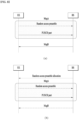
- FIG.7 illustrates random access procedures.
- FIG. 7(a) illustrates the contention-based random access procedure
- FIG. 7(b) illustrates the dedicated random access procedure.
- the contention-based random access procedure includes the following four steps.
- the messages transmitted in steps 1 to 4 may be referred to as message 1 (Msg1) to message 4 (Msg4), respectively.
- the UE may receive random access information in system information from the BS.
- the UE When the UE needs random access, the UE transmits an RACH preamble to the BS as in step 1.
- the BS may identify each RACH preamble by a time/frequency resource (RACH occasion (RO)) in which the RACH preamble is transmitted, and a preamble index (PI).
- RACH occasion RO
- PI preamble index
- the BS Upon receipt of the RACH preamble from the UE, the BS transmits an RAR message to the UE as in step 2.
- the UE monitors an L1/L2 PDCCH with a cyclic redundancy check (CRC) masked with a random access-RNTI (RA-RNTI), including scheduling information for the RAR message, within a preconfigured time window (e.g., ra-ResponseWindow).
- CRC cyclic redundancy check
- RA-RNTI random access-RNTI
- the PDCCH masked with the RA-RNTI may be transmitted only in a common search space.
- the UE may receive an RAR message on a PDSCH indicated by the scheduling information.
- the UE checks whether there is RAR information directed to the UE in the RAR message.
- the presence or absence of the RAR information directed to the UE may be determined by checking whether there is a random access preamble ID (RAPID) for the preamble transmitted by the UE.
- RAPID random access preamble ID
- the index of the preamble transmitted by the UE may be identical to the RAPID.
- the RAR information includes the index of the corresponding RACH preamble, timing offset information (e.g., timing advance command (TAC)) for UL synchronization, UL scheduling information (e.g., UL grant) for Msg3 transmission, and UE temporary identification information (e.g., temporary-C-RNTI (TC-RNTI)).
- TAC timing advance command
- TC-RNTI temporary-C-RNTI
- Msg3 UL-SCH data
- Msg3 may include the ID (or global ID) of the UE.
- Msg3 may include RRC connection request-related information (e.g., RRCSetupRequest message) for initial access.
- Msg3 may include a buffer status report (BSR) on the amount of data available for transmission at the UE.
- BSR buffer status report
- the BS After receiving the UL-SCH data, the BS transmits a contention resolution message (Msg4) to the UE as in step 4.
- Msg4 may include the ID of the UE and/or RRC connection-related information (e.g., an RRCSetup message).
- RRC connection-related information e.g., an RRCSetup message.
- the dedicated random access procedure includes the following three steps. Messages transmitted in steps 0 to 2 may be referred to as Msg0 to Msg2, respectively.
- the BS may trigger the dedicated random access procedure by a PDCCH serving the purpose of commanding RACH preamble transmission (hereinafter, referred to as a PDCCH order).
- Steps 1 and 2 of the dedicated random access procedure may be the same as steps 1 and 2 of the contention-based random access procedure.
- DCI format 1_0 is used to initiate a non-contention-based random access procedure by a PDCCH order.
- DCI format 1_0 is used to schedule a PDSCH in one DL cell.
- the CRC of DCI format 1_0 is scrambled with a C-RNTI, and all bits of a "Frequency domain resource assignment" field are 1s, DCI format 1_0 is used as a PDCCH order indicating a random access procedure.
- the fields of DCI format 1_0 are configured as follows.
- DCI format 1_0 When DCI format 1_0 does not correspond to a PDCCH order, DCI format 1_0 includes fields used to schedule a PDSCH (e.g., a time domain resource assignment, a modulation and coding scheme (MCS), an HARQ process number, a PDSCH-to-HARQ_feedback timing indicator, and so on).
- a PDSCH e.g., a time domain resource assignment, a modulation and coding scheme (MCS), an HARQ process number, a PDSCH-to-HARQ_feedback timing indicator, and so on.
- MCS modulation and coding scheme
- the NR system may require lower latency than conventional systems.
- the random access may be terminated, that is, contention may be resolved only if the UE and BS sequentially succeed in LBT in all steps of the 4-step random access procedure. If the LBT fails even in one step of the 4-step random access procedure, resource efficiency may decrease, and latency may increase. If the LBT fails in a scheduling/transmission process associated with Msg2 or Msg3, the resource efficiency may significantly decrease, and the latency may significantly increase.
- low latency may be required in various scenarios of the NR system. Therefore, a 2-step random access procedure may be performed in the L-band as well.
- the 2-step random access procedure may include two steps: transmission of a UL signal (referred to as MsgA) from the UE to the BS and transmission of a DL signal (referred to as MsgB) from the BS to the UE.
- MsgA a UL signal
- MsgB a DL signal
- a random access preamble and a PUSCH part may be transmitted together in a non-contention random access procedure as shown in FIG. 8(b) .
- the BS may transmit a PDCCH for scheduling Msg. B to the UE, which may be referred to as a Msg. B PDCCH.
- Methods related to the configuration of a plurality of reference points to be described below are related to uplink transmission and may be equally applied to a downlink signal transmission method in the NR system or LTE system described above, and needless to say, the technological spirit proposed in the present specification may be modified or replaced according to the term, expression, structure, etc. defined in each system to be implemented in the corresponding system.
- FIG. 9 shows an example in which a reference point is implemented in an NTN.
- a frequency band considered for an NR NTN service may be mainly a band of 2 GHz for a band equal to or less than 6 GHz and a band of DL 20 GHz and UL 30 GHz for a band equal to or greater than 6 GHz.
- the cell coverage may be changed from as small as 1000 km to as large as 3500 km.
- the BS needs to configure a large maximum timing advance (TA) value for uplink transmission to provide a service to all UEs in the corresponding cell.
- TA timing advance
- a plurality of reference points in one cell may be defined.
- the reference point may be a point used as a reference when a UE configures TA for UL transmission.
- the BS may solve the problem of increasing the resource overhead of the container indicating a TA command by introducing a plurality of reference points.
- the present specification proposes a method of configuring a plurality of reference points, a method of selecting a reference point of a UE, and an RACH process configuring method based on a plurality of reference points.
- the following methods may be considered as a method for the BS to configure a plurality of reference points and to inform the UE.
- Method 3-1-1 Method of distinguishing multiple reference points using independent RACH configuration (e.g., RACH occasion)]
- the BS may independently configure/instruct the RACH configuration (e.g., RACH occasion) for each of the cell-specific multiple reference points through higher-layer signaling (e.g., SIB1) to the UE.
- RACH configuration e.g., RACH occasion
- SIB1 higher-layer signaling
- At least one RACH configuration needs to be transmitted.
- the total number of the independently configured/indicated RACH configurations may indicate the total number of reference points provided by a corresponding cell.
- a specific example is as follows.
- Each RACH configuration may be independently indicated for each RACH configuration index, and a value of the RACH configuration index may be configured to 0 to a Max RACH configuration number -1.
- the Max RACH configuration number may be a value that is preconfigured in a system.
- an RACH configuration index 0 needs to always be indicated.
- the BS may select one of values from 0 to a Max RACH configuration number - 1 and may indicate an RACH configuration of the selected value.
- RACH configuration index 0 When only one RACH configuration (i.e., RACH configuration index 0) is transmitted, devices in a corresponding cell may be operated based on a single reference point.
- a parameter e.g., msg1-FrequencyStart
- a start PRB within UL BWP
- RACH occasions corresponding to the respective parameters may be FDMed.
- a start PRB may be indicated based on a subcarrier spacing (SCS) of a corresponding UL BWP, and thus the BS may FDM ROs for each reference point in consideration of an SCS value of a corresponding UL BWP, an SCS value of a PRACH preamble, a length of a PRACH sequence, and the like.
- SCS subcarrier spacing
- the start PRB of the reference point n+1 may be configured to be greater than X+12 in consideration of the case in which a reference point n+1 is FDMed after a reference point n assuming that the SCS of the corresponding UL BWP is 30 kHz, the start PRB of the reference point n is X, and the L-839 ZC (Zadoff Chu) sequence is configured to use SCS of 5 kHz at the reference point n.
- the start PRB of the reference point n+1 may be configured to be greater than X+24 in consideration of the case in which a reference point n+1 is FDMed after a reference point n assuming that the SCS of the corresponding UL BWP is 15 kHz, the start PRB of the reference point n is X, and the L-139 ZC sequence is configured to use SCS of 30 kHz at the reference point n.
- the BS may transmit additional information for each reference point as well as RACH configurations that are independently transmitted.
- the BS may provide such additional information to a UE in order to help the UE to select an appropriate reference point among a plurality of reference points using a corresponding value.
- Position information (e.g., coordinates (latitude, longitude), altitude etc.) of each reference point may be provided via higher-layer signaling.
- An initial TA value (e.g., common TA) to be used to transmit a PRACH preamble in an RO corresponding to each reference point may be provided via higher-layer signaling.
- the BS may configure a corresponding initial TA value for each reference point and may finely adjust the remaining TA through an existing RAR TA command field.
- a reference signal received power (RSRP) range, an angle of arrival (AOA) range, or the like may be configured for each reference point.
- RSRP reference signal received power
- AOA angle of arrival
- time and/or frequency resources of each RO may be configured not to overlap.
- time and/or frequency resources corresponding to respective ROs for a plurality of reference points overlap entirely or partially the UE may determine that reference points corresponding to overlapping ROs and related information are invalid.
- an RO according to an RACH configuration indicated to be initial e.g., RACH configuration index 0
- the UE may determine that only a reference point corresponding to a default RO among overlapping reference points and related information are valid.
- ROs may be configured to prevent time and/or frequency resources between the ROs from overlapping.
- each RO may be configured via TDM instead of FDM.
- the BS may configure RO configurations for respective reference points to prevent a RACH slot between RO configurations from overlapping.
- the BS may configure a period, a starting offset value, and the like to prevent an RACH slot from overlapping by differently configuring the period, the starting offset value, and the like for the respective ROs.
- Method 3-1-2 Method of successively arranging ROs assigned to a plurality of reference points on time axis when BS configures plurality of reference points
- a second method may be a method of successively arranging ROs assigned to a plurality of reference points on the time axis when the plurality of reference points are configured.
- ROs on the frequency domain may be included in the same frequency band.
- the BS may provide an initial TA value (common TA) configured for each reference point to the UE, but may not separately inform RO information mapped to each reference point, and may be used when only entire RO information is provided.
- the BS may arrange ROs corresponding to the plurality of reference points in the form of TDM, may map a reference point having a large TA value to an RO located at a position earlier in time, and may map a reference point having a small TA value to an RO located at a position late in time. This may be to ensure that RACH transmission of any UE present in a corresponding cell does not deviate from a PRACH preamble reception window (i.e., RO) of the BS.
- a PRACH preamble reception window i.e., RO
- FIG. 10 shows an example in which ROs corresponding to a plurality of reference points are arranged in the form of TDM. It may be assumed that one RO occupies 4 OFDM symbols and that RO1 to RO3 are arranged in the form of TDM. It may be assumed that delay of a UE is 3 OFDM symbols (round trip delay 6 OFDM symbol).
- the PRACH preamble may be divided into 2 OFDM symbols for each of RO 2 and RO 3 and may be received from a BS reception point of view.
- a RACH process of the UE may fail.
- the corresponding PRACH preamble does not damage a UL signal/channel of other UEs.
- FIG. 11 A detailed example to which Method 3-1-2 is applied may be shown in FIG. 11 .
- the number of a plurality of reference points may be three, four ROs may be FDMed for each reference point, the four FDMed ROs may be included in one RO group, and a plurality of RO groups may be successively arranged on the time axis.
- Four ROs positioned in the same time axis may be mapped one-to-one to one reference point.
- a plurality of TDMed ROs on the time axis may be grouped, and the grouped ROs may be mapped to one reference point.
- ROs located on the same frequency axis may be mapped to one reference point.
- Method 3-1-3 Method of configuring SSBs (or a SSB group) to be assigned to different reference points
- a third method may be a method of configuring SSBs (or a SSB group including a plurality of SSBs) to be assigned to different reference points.
- the BS may indicate an RACH configuration using one of the following methods.
- a single RACH configuration for only a SSB group to which a corresponding SSB belongs may be transmitted through a higher-layer signaling (e.g., SIB1) corresponding to each SSB.
- a higher-layer signaling overhead for a RACH configuration may be maintained at an existing level.
- a plurality of RACH configurations (i.e., independent RACH configuration for each SSB group) for all SSB groups may be transmitted through higher-layer signaling (e.g., SIB1) corresponding to each SSB.
- SIB1 higher-layer signaling
- the BS may need to inform the UE which SSB indexes belong to each SSB group.
- a common TA value (e.g., z) corresponding to a specific reference point may be mapped to a specific SSB (e.g., SSB index x) and an RO (e.g., RO index y) corresponding thereto, and a common TA value (e.g., z') corresponding to another reference point may be mapped to another SSB (e.g., SSB index x') and an RO (e.g., RO index y') corresponding thereto.
- the BS may need to provide a sharp beam in order to use this method. When a beam is not a sharp beam, resource waste of a DL region reserved for SSB transmission and subsequent channel transmission related thereto may occur.
- a cell ID may be set differently for each SSB group than before.
- an existing cell ID may be configured, and a sub cell ID may be configured as a sub-concept of the existing cell ID.
- a plurality of additionally assigned cell ID values may be assigned to respective SSB groups separately from the existing cell ID value.
- a plurality of SSB groups may be present in one SSB group per cell ID. In the state in which the UE recognizes one cell based on a cell ID corresponding to one SSB group, the UE may select an SSB index and may perform an RACH process in the same method as in the existing NR system.
- a plurality of ROs belonging to the RO group may be mapped for respective different SSB indexes or SSB groups. That is, this method may be used when an SSB or an SSB group is mapped to each reference point after different ROs are assigned for respective reference points.
- the RACH configuration may be maintained without change (i.e., the same RACH configuration is given to all SSBs (or SSB group)), mapping of SSBs (or SSB group) to ROs may be configured to one-to-one mapping for each SSB (or SSB group), and different reference points may be assigned for the respective SSBs (or SSB group). That is, the BS may indicate reference points (and/or common TA values) for respective SSBs or SSB groups through higher-layer signaling.
- SSB-to-RO mapping is configured to one-to-one mapping
- SSB index 0 may be mapped to an RO of an even (RACH) slot
- SSB index 1 may be mapped to an RO of an odd (RACH) slot.
- ROs assigned to different reference points may be TDMed.
- the number of SSB indexes is six
- an SSB group index corresponding to SSB indexes grouped by three is two
- three ROs for each RACH slot are FDMed (and/or TDMed) and are present
- an RACH slot is present in every slot.
- SSB-to-RO mapping is configured to one-to-one mapping
- SSB group index 0 may be mapped to an RO of an even (RACH) slot
- SSB group index 1 may be mapped to an RO of an odd (RACH) slot.
- three SSB indices belonging to SSB group index 0 may be mapped one-to-one to different ROs.
- Three SSB indices belonging to SSB group index 1 may be mapped one-to-one to different ROs.
- ROs assigned to different reference points may be TDMed.
- Different ROs assigned to the same reference point may be FDMed.
- a method of selecting an appropriate reference point from among a plurality of reference points by the UE may be divided according to a method of configuring a reference point by the BS (the methods described in Section 3.1).
- Method 3-2-1 Method of selecting appropriate reference point of UE when independent RACH configurations are configured for respective reference points
- the UE may sequentially list appropriate reference points, which may be regarded as a method of determining priorities among a plurality of reference points.
- Method 3-2-1-A This may be a method in which the UE compares physical position information for each reference point and preferentially selects the reference point closest to the current UE position.
- Method 3-2-1-A may be used by the UE that does not know an accurate position of the BS.
- the UE may preferentially select the nearest reference point using a position of the UE and the position of the reference point.
- the UE may select an RO corresponding to the selected reference point according to Method 3-2-1-A, and may transmit a PRACH preamble using a preconfigured initial TA value.
- Method 3-2-1-B This may be a method in which the UE calculates an appropriate TA value using position information of the UE and the BS and then selects the most appropriate reference point first according to the initial TA value for each reference point configured by the UE.
- the method may be used by the UE that is capable of accurately know the position of the BS and the position of the UE itself.
- the UE may be configured to calculate an appropriate TA value (reference TA value) and then to preferentially select a reference point that is smaller than the corresponding TA value and provides the largest initial TA.
- the BS indicates initial TA values of three reference points with a, b, and c (where a ⁇ b ⁇ c)
- a reference TA value calculated using position information of the UE and the BS is x (the BS may make a value of a as small as possible and a value of x is larger than a).
- the UE may select an RO corresponding to the reference point selected according to Method 3-2-1-B and may transmit a PRACH preamble using a preconfigured initial TA value for a corresponding reference point.
- Method 3-2-1-C This may be a method in which the BS preferentially selects a reference point assigned to a position corresponding to an RSRP of the UE based on a preconfigured RSRP ranged for reference point selection. This may be used by the UE when the UE does not know an accurate position of the UE.
- the BS may indicate an RSRP threshold in order to divide an RSRP range for reference point selection. When the number of the indicated RSRP thresholds is X, the number of all RSRP ranges may be X+1, and when the RSRP thresholds are listed in small order (or in large order), the RSRP thresholds may be expressed to RSRP range #X from RSRP range #0.
- the UE may select an RO corresponding to the reference point selected according to Method 3-2-1-C and may transmit a PRACH preamble using a preconfigured initial TA value for a corresponding reference point.
- Method 3-2-1-D This may be a method in which the BS preferentially selects a reference point assigned to an AOA of the UE based on a preconfigured AOA range for reference point selection.
- the BS may indicate an AOA threshold in order to divide an AOA for reference point selection.
- the number of indicated AOA thresholds is Y
- the number of all AOA ranges is Y + 1
- the AOA thresholds may be expressed to AOA range #Y from AOA range #0.
- the UE may select an RO corresponding to the reference point selected according to Method 3-2-1-D and may transmit a PRACH preamble using a preconfigured initial TA value for the corresponding reference point.
- Method 3-2-1-E This may be a method in which the UE selects a reference point in according to the RACH configuration index order (or reverse order) configured by the BS via higher-layer signaling.
- the priority of the reference point may be configured according to the order indicated by the BS.
- the BS may align the order of the reference point index by establishing a specific reference in order to support an operation of the UE.
- a parameter to be a specific reference may be a distance from a cell center and/or an initially configured TA value for each reference point.
- Method 3-2-2 Method of selecting appropriate reference point of UE when ROs for plurality of reference points are successively arranged on time axis
- the UE may select a reference point as follows.
- This may be a method in which the UE selects a reference point with the smallest initial TA value, and transmits a PRACH preamble in the first RO among successively arranged ROs on the time axis, provided from the BS.
- an initial TA value of a reference point selected by the UE is smaller than a round trip delay value of an actual UE, a PRACH preamble is transmitted on the first RO, and thus since the PRACH preamble is transmitted somewhere among the ROs successively arranged on the time axis after the first RO, UL signal/channel transmission of other UEs may not be interrupted.
- the UE may select a reference point having the next smallest initial TA value. As a time interval between an actual round trip delay value of the UE and the initial TA value of the initially selected reference point is increased, an RACH process may be disadvantageously lengthy.
- This may be a method in which the UE selects a reference point with the largest initial TA value, and transmits a PRACH preamble in the last RO among ROs successively arranged on the time axis, provided from the BS.
- a PRACH preamble may be transmitted on the last RO, and thus since the PRACH preamble is transmitted somewhere among the ROs successively arranged on the time axis before the last RO, UL signal/channel transmission of other UEs may not be interrupted.
- the UE may select a reference point having the next greatest reference point. As a time interval between an actual round trip delay value of the UE and the initial TA value of the initially selected reference point is increased, an RACH process may be disadvantageously lengthy.
- Method 3-2-2 when RAR transmitted by the BS is detected and a Msg. 3 scheduling configuration is transmitted in an RAR window corresponding to an RO in which the UE transmits a PRACH preamble, the UE may determine that the Msg. 1 PRACH preamble is successfully transmitted and may transmit the Msg. 3 PUSCH.
- the UE when the UE transmits a PRACH preamble using RO1 as a target, the UE needs to monitor an RAR window corresponding thereto.
- the BS when a corresponding PRACH preamble is received in another RO (e.g., RO3) but not RO1, the BS may transmit RAR in another RAR window (RAR window 3) but not RAR window 1.
- the UE may determine that RAR reception fails and may retransmit the Msg. 1 PRACH preamble.
- Method 3-1-1 when the BS provides additional information for each reference point, the operation of the UE in Method 3-2-1 may also be used in Method 3-2-2.
- Method 3-2-3 Method of selecting appropriate reference point when respective SSBs for SSB group) are configured to be assigned to different reference points
- the UE may select a reference point as follows.
- the UE may select the most visible SSB index (e.g., the largest RSRP value) among the SSB indexes transmitted by the BS and may select the reference point mapped to the corresponding SSB index or the SSB group to which the corresponding SSB index belongs. Then, the UE may know the initial TA value through the RACH configuration for the reference point and may also know the assigned RO information, and thus may transmit the PRACH preamble accordingly.
- the most visible SSB index e.g., the largest RSRP value
- a plurality of reference points may also be appropriately used using the following method in a RACH process to be performed by the UE.
- Reference points to be used for respective specific RACH processes among a plurality of reference points may be differently configured.
- a specific reference point e.g., default reference point
- one of a plurality of reference points may be selected and used by the UE in other RACH processs (e.g., PDCCH ordered RACH process) except for initial access.
- the UE may determine the priority through a method of selecting an appropriate reference point from among a plurality of reference points.
- the BS may indicate a reference point to be used by the UE in other RACH processes except for initial access through perform higher-layer signalling (e.g., UE specific RRC signalling), Msg. 2 RAR (or PDCCH scheduling Msg. 2 PDCCH) and/or Msg. 4 PDSCH (or PDCCH scheduling Msg. 4 PDSCH).
- higher-layer signalling e.g., UE specific RRC signalling
- Msg. 2 RAR or PDCCH scheduling Msg. 2 PDCCH
- Msg. 4 PDSCH or PDCCH scheduling Msg. 4 PDSCH.
- the BS may indicate a reference point to be used by the UE among a plurality of reference points, through a DCI field (e.g., DCI format 1-0).
- a DCI field e.g., DCI format 1-0
- the BS may transmit a reference point index in order to indicate a reference point.
- the BS may also indirectly indicate a reference point by indicating an initial TA value assigned to each reference point or an assigned RO.
- a method of determining priority among a plurality of reference points and performing a RACH process while changing a reference point according to a predefined rule during a RACH process may be considered.
- the UE may transmit a PRACH preamble using a reference point with the highest priority after determining a priority for each reference point, and then when RAR reception fails, the UE may transmit a PRACH preamble using a reference point with the next highest priority.
- Method 3-3-2 may be applied when the UE needs to perform an RACH process using a trial and error method because a plurality of ROs is configured to the UE through an RACH configuration of the BS but mapping information between a plurality of reference points and ROs is not configured to the UE.
- RACH configurations i.e., RO configuration
- RO configurations i.e., RO configuration
- a method in which the UE changes the reference point while maintain transmission power of Msg. 1 PRACH preamble may be considered.
- This method may have an advantage in that RAR is capable of being rapidly received when there is no problem in TX power.
- the UE may rapidly change the selected reference point to another reference point.
- the UE may maintain a reference point and may first perform ramping on transmission power of a Msg. 1 PRACH preamble.
- the RAR may be rapidly received.
- TX power ramping may be advantageously performed first.
- Method 3-3-3 Method of differently configuring PRACH preamble transmission power depending on cases when one reference point or plurality of reference points are assigned to respective SSB indexes for SSB groups)]
- PRACH preamble transmission power may be different configured. That is, when the BS defines reference points for respective SSB indexes or SSB groups, the UE may perform an operation of changing an SSB index and/ or a reference point during a RACH process.
- the UE may transmit the PRACH preamble while maintaining previous PRACH preamble transmission power. Since only the SSB index is changed and the common TA and RO configurations are not changed, the transmission power may be maintained.
- the UE may change PRACH preamble transmission power to initial transmission power and may transmit a PRACH preamble.
- Common TA and RO configurations may be changed while a reference point is changed, and thus transmission power may be configured to initial transmission power.
- a rule may be defined such that the BS informs the UE of information as to whether the proposed methods are applied (or information about rules of the proposed methods) through a predefined signal (e.g., a physical layer signal or a higher-layer signal).
- the higher layer may include, for example, one or more of functional layers such as MAC, RLC, PDCP, RRC, or SDAP.
- Methods, embodiments, or descriptions for implementing the method proposed in the present specification may be separately applied or one or more methods (embodiments, or descriptions) may be combined and applied.
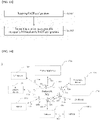
- FIG. 13 is a flowchart of a signal transmission/reception method according to embodiments of the present disclosure.
- embodiments of the present disclosure may be performed by a UE, and may include receiving RACH configurations (S1301), and transmitting a random access preamble on a specific RO based on the RACH configurations (S1303).
- the number of reference points in a cell may be derived based on the number of RACH configurations.
- the reference points may have each initial TA value for an RACH process.
- Each of the RACH configurations may be indicated by an RACH configuration index.
- the number of RACH configuration indexes may be the same as the number of reference points.
- the BS may also indicate a plurality of reference points using different methods among the methods of Section 3.1.
- the UE may select one of reference points based on each initial TA value.
- the UE may transmit a random access preamble based on a TA value of one selected reference point.
- the UE may determine a reference TA value and may select a reference point having the greatest TA value among reference points having a smaller TA value than the determined reference TA value.
- the UE may also select one of a plurality of reference points using different methods among the methods of Section 3.2.
- the UE may change the selected reference point during an RACH process using Method 3-3-2.
- ramping may be performed on transmission power of a random access preamble based on that reception of Random Access Response (RAR) corresponding to the random access preamble fails, the random access preamble with transmission power on which ramping is performed, and the selected reference point may be maintained.
- RAR Random Access Response
- the selected reference point may be changed to another reference point based on that reception of Random Access Response (RAR) corresponding to a random access preamble fails, the random access preamble may be retransmitted based on the initial TA value of another reference point, and power transmission of the random access preamble may be maintained.
- RAR Random Access Response
- one or more of the operations described with reference to FIGS. 1 to 12 and/or one or more of the operations described in Sections 3.1 to 3.3 may be combined and may be additionally performed.
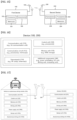
- FIG. 14 illustrates a communication system 1 applied to the present disclosure.
- the communication system 1 applied to the present disclosure includes wireless devices, BSs, and a network.
- a wireless device is a device performing communication using radio access technology (RAT) (e.g., 5G NR (or New RAT) or LTE), also referred to as a communication/radio/5G device.
- RAT radio access technology
- the wireless devices may include, not limited to, a robot 100a, vehicles 100b-1 and 100b-2, an extended reality (XR) device 100c, a hand-held device 100d, a home appliance 100e, an IoT device 100f, and an artificial intelligence (AI) device/server 400.
- RAT radio access technology
- XR extended reality
- AI artificial intelligence
- the vehicles may include a vehicle having a wireless communication function, an autonomous driving vehicle, and a vehicle capable of vehicle-to-vehicle (V2V) communication.
- the vehicles may include an unmanned aerial vehicle (UAV) (e.g., a drone).
- UAV unmanned aerial vehicle
- the XR device may include an augmented reality (AR)/virtual reality (VR)/mixed reality (MR) device and may be implemented in the form of a head-mounted device (HMD), a head-up display (HUD) mounted in a vehicle, a television (TV), a smartphone, a computer, a wearable device, a home appliance, a digital signage, a vehicle, a robot, and so on.
- AR augmented reality
- VR virtual reality
- MR mixeded reality
- the hand-held device may include a smartphone, a smart pad, a wearable device (e.g., a smart watch or smart glasses), and a computer (e.g., a laptop).
- the home appliance may include a TV, a refrigerator, a washing machine, and so on.
- the IoT device may include a sensor, a smart meter, and so on.
- the BSs and the network may be implemented as wireless devices, and a specific wireless device 200a may operate as a BS/network node for other wireless devices.
- the wireless devices 100a to 100f may be connected to the network 300 via the BSs 200.
- An AI technology may be applied to the wireless devices 100a to 100f, and the wireless devices 100a to 100f may be connected to the AI server 400 via the network 300.
- the network 300 may be configured using a 3G network, a 4G (e.g., LTE) network, or a 5G (e.g., NR) network.
- the wireless devices 100a to 100f may communicate with each other through the BSs 200/network 300, the wireless devices 100a to 100f may perform direct communication (e.g., sidelink communication) with each other without intervention of the BSs/network.
- the vehicles 100b-1 and 100b-2 may perform direct communication (e.g., V2V/vehicle-to-everything (V2X) communication).
- V2X vehicle-to-everything
- the IoT device e.g., a sensor
- IoT devices e.g., sensors
- Wireless communication/connections 150a, 150b, and 150c may be established between the wireless devices 100a to 100f/BS 200 and between the BSs 200.
- the wireless communication/connections may be established through various RATs (e.g., 5G NR) such as UL/DL communication 150a, sidelink communication 150b (or, D2D communication), or inter-BS communication (e.g., relay or integrated access backhaul (IAB)).
- RATs e.g., 5G NR
- UL/DL communication 150a UL/DL communication 150a
- sidelink communication 150b or, D2D communication
- inter-BS communication e.g., relay or integrated access backhaul (IAB)
- Wireless signals may be transmitted and received between the wireless devices, between the wireless devices and the BSs, and between the BSs through the wireless communication/connections 150a, 150b, and 150c.
- signals may be transmitted and receive don various physical channels through the wireless communication/connections 150a, 150b and 150c.
- various configuration information configuring processes various signal processing processes (e.g., channel encoding/decoding, modulation/demodulation, and resource mapping/demapping), and resource allocation processes, for transmitting/receiving wireless signals, may be performed based on the various proposals of the present disclosure.
- various signal processing processes e.g., channel encoding/decoding, modulation/demodulation, and resource mapping/demapping
- resource allocation processes for transmitting/receiving wireless signals
- FIG. 15 illustrates wireless devices applicable to the present disclosure.
- a first wireless device 100 and a second wireless device 200 may transmit wireless signals through a variety of RATs (e.g., LTE and NR).
- RATs e.g., LTE and NR
- the first wireless device 100 and the second wireless device 200 ⁇ may correspond to ⁇ the wireless device 100x and the BS 200 ⁇ and/or ⁇ the wireless device 100x and the wireless device 100x ⁇ of FIG. 14 .
- the first wireless device 100 may include one or more processors 102 and one or more memories 104, and further include one or more transceivers 106 and/or one or more antennas 108.
- the processor(s) 102 may control the memory(s) 104 and/or the transceiver(s) 106 and may be configured to implement the descriptions, functions, procedures, proposals, methods, and/or operation flowcharts disclosed in this document.
- the processor(s) 102 may process information in the memory(s) 104 to generate first information/signals and then transmit wireless signals including the first information/signals through the transceiver(s) 106.
- the processor(s) 102 may receive wireless signals including second information/signals through the transceiver(s) 106 and then store information obtained by processing the second information/signals in the memory(s) 104.
- the memory(s) 104 may be connected to the processor(s) 102 and may store various pieces of information related to operations of the processor(s) 102.
- the memory(s) 104 may store software code including instructions for performing all or a part of processes controlled by the processor(s) 102 or for performing the descriptions, functions, procedures, proposals, methods, and/or operation flowcharts disclosed in this document.
- the processor(s) 102 and the memory(s) 104 may be a part of a communication modem/circuit/chip designed to implement RAT (e.g., LTE or NR).
- the transceiver(s) 106 may be connected to the processor(s) 102 and transmit and/or receive wireless signals through the one or more antennas 108.
- Each of the transceiver(s) 106 may include a transmitter and/or a receiver.
- the transceiver(s) 106 may be interchangeably used with radio frequency (RF) unit(s).
- the wireless device may be a communication modem/circuit/chip.
- the second wireless device 200 may include one or more processors 202 and one or more memories 204, and further include one or more transceivers 206 and/or one or more antennas 208.
- the processor(s) 202 may control the memory(s) 204 and/or the transceiver(s) 206 and may be configured to implement the descriptions, functions, procedures, proposals, methods, and/or operation flowcharts disclosed in this document.
- the processor(s) 202 may process information in the memory(s) 204 to generate third information/signals and then transmit wireless signals including the third information/signals through the transceiver(s) 206.
- the processor(s) 202 may receive wireless signals including fourth information/signals through the transceiver(s) 106 and then store information obtained by processing the fourth information/signals in the memory(s) 204.
- the memory(s) 204 may be connected to the processor(s) 202 and store various pieces of information related to operations of the processor(s) 202.
- the memory(s) 204 may store software code including instructions for performing all or a part of processes controlled by the processor(s) 202 or for performing the descriptions, functions, procedures, proposals, methods, and/or operation flowcharts disclosed in this document.
- the processor(s) 202 and the memory(s) 204 may be a part of a communication modem/circuit/chip designed to implement RAT (e.g., LTE or NR).
- the transceiver(s) 206 may be connected to the processor(s) 202 and transmit and/or receive wireless signals through the one or more antennas 208.
- Each of the transceiver(s) 206 may include a transmitter and/or a receiver.
- the transceiver(s) 206 may be interchangeably used with RF unit(s).
- the wireless device may be a communication modem/circuit/chip.
- One or more protocol layers may be implemented by, not limited to, one or more processors 102 and 202.
- the one or more processors 102 and 202 may implement one or more layers (e.g., functional layers such as physical (PHY), medium access control (MAC), radio link control (RLC), packet data convergence protocol (PDCP), RRC, and service data adaptation protocol (SDAP)).
- the one or more processors 102 and 202 may generate one or more protocol data units (PDUs) and/or one or more service data Units (SDUs) according to the descriptions, functions, procedures, proposals, methods, and/or operation flowcharts disclosed in this document.
- PDUs protocol data units
- SDUs service data Units
- the one or more processors 102 and 202 may generate messages, control information, data, or information according to the descriptions, functions, procedures, proposals, methods, and/or operation flowcharts disclosed in this document and provide the messages, control information, data, or information to one or more transceivers 106 and 206.
- the one or more processors 102 and 202 may generate signals (e.g., baseband signals) including PDUs, SDUs, messages, control information, data, or information according to the descriptions, functions, procedures, proposals, methods, and/or operation flowcharts disclosed in this document and provide the generated signals to the one or more transceivers 106 and 206.
- the one or more processors 102 and 202 may receive the signals (e.g., baseband signals) from the one or more transceivers 106 and 206 and acquire the PDUs, SDUs, messages, control information, data, or information according to the descriptions, functions, procedures, proposals, methods, and/or operation flowcharts disclosed in this document.
- signals e.g., baseband signals
- the one or more processors 102 and 202 may be referred to as controllers, microcontrollers, microprocessors, or microcomputers.
- the one or more processors 102 and 202 may be implemented by hardware, firmware, software, or a combination thereof.
- ASICs application specific integrated circuits
- DSPs digital signal processors
- DSPDs digital signal processing devices
- PLDs programmable logic devices
- FPGAs field programmable gate arrays
- the descriptions, functions, procedures, proposals, methods, and/or operation flowcharts disclosed in this document may be implemented using firmware or software, and the firmware or software may be configured to include the modules, procedures, or functions.
- Firmware or software configured to perform the descriptions, functions, procedures, proposals, methods, and/or operation flowcharts disclosed in this document may be included in the one or more processors 102 and 202 or may be stored in the one or more memories 104 and 204 and executed by the one or more processors 102 and 202.
- the descriptions, functions, procedures, proposals, methods, and/or operation flowcharts disclosed in this document may be implemented using firmware or software in the form of code, an instruction, and/or a set of instructions.
- the one or more memories 104 and 204 may be connected to the one or more processors 102 and 202 and store various types of data, signals, messages, information, programs, code, instructions, and/or commands.
- the one or more memories 104 and 204 may be configured to include read-only memories (ROMs), random access memories (RAMs), electrically erasable programmable read-only memories (EPROMs), flash memories, hard drives, registers, cash memories, computer-readable storage media, and/or combinations thereof.
- the one or more memories 104 and 204 may be located at the interior and/or exterior of the one or more processors 102 and 202.
- the one or more memories 104 and 204 may be connected to the one or more processors 102 and 202 through various technologies such as wired or wireless connection.
- the one or more transceivers 106 and 206 may transmit user data, control information, and/or wireless signals/channels, mentioned in the methods and/or operation flowcharts of this document, to one or more other devices.
- the one or more transceivers 106 and 206 may receive user data, control information, and/or wireless signals/channels, mentioned in the descriptions, functions, procedures, proposals, methods, and/or operation flowcharts disclosed in this document, from one or more other devices.
- the one or more transceivers 106 and 206 may be connected to the one or more processors 102 and 202 and transmit and receive wireless signals.
- the one or more processors 102 and 202 may perform control so that the one or more transceivers 106 and 206 may transmit user data, control information, or wireless signals to one or more other devices.
- the one or more processors 102 and 202 may perform control so that the one or more transceivers 106 and 206 may receive user data, control information, or wireless signals from one or more other devices.
- the one or more transceivers 106 and 206 may be connected to the one or more antennas 108 and 208 and the one or more transceivers 106 and 206 may be configured to transmit and receive user data, control information, and/or wireless signals/channels, mentioned in the descriptions, functions, procedures, proposals, methods, and/or operation flowcharts disclosed in this document, through the one or more antennas 108 and 208.
- the one or more antennas may be a plurality of physical antennas or a plurality of logical antennas (e.g., antenna ports).
- the one or more transceivers 106 and 206 may convert received wireless signals/channels from RF band signals into baseband signals in order to process received user data, control information, and wireless signals/channels using the one or more processors 102 and 202.
- the one or more transceivers 106 and 206 may convert the user data, control information, and wireless signals/channels processed using the one or more processors 102 and 202 from the baseband signals into the RF band signals.
- the one or more transceivers 106 and 206 may include (analog) oscillators and/or filters.
- FIG. 16 illustrates another example of a wireless device applied to the present disclosure.
- the wireless device may be implemented in various forms according to a use case/service (refer to FIG. 14 ).
- wireless devices 100 and 200 may correspond to the wireless devices 100 and 200 of FIG. 15 and may be configured to include various elements, components, units/portions, and/or modules.
- each of the wireless devices 100 and 200 may include a communication unit 110, a control unit 120, a memory unit 130, and additional components 140.
- the communication unit 110 may include a communication circuit 112 and transceiver(s) 114.
- the communication circuit 112 may include the one or more processors 102 and 202 and/or the one or more memories 104 and 204 of FIG. 15 .
- the transceiver(s) 114 may include the one or more transceivers 106 and 206 and/or the one or more antennas 108 and 208 of FIG.
- the control unit 120 is electrically connected to the communication unit 110, the memory 130, and the additional components 140 and provides overall control to the wireless device. For example, the control unit 120 may control an electric/mechanical operation of the wireless device based on programs/code/instructions/information stored in the memory unit 130.
- the control unit 120 may transmit the information stored in the memory unit 130 to the outside (e.g., other communication devices) via the communication unit 110 through a wireless/wired interface or store, in the memory unit 130, information received through the wireless/wired interface from the outside (e.g., other communication devices) via the communication unit 110.
- the additional components 140 may be configured in various manners according to type of the wireless device.
- the additional components 140 may include at least one of a power unit/battery, input/output (I/O) unit, a driving unit, and a computing unit.
- the wireless device may be implemented in the form of, not limited to, the robot (100a of FIG. 14 ), the vehicles (100b-1 and 100b-2 of FIG. 14 ), the XR device (100c of FIG. 14 ), the hand-held device (100d of FIG. 14 ), the home appliance (100e of FIG. 14 ), the IoT device (100f of FIG.
- the wireless device may be mobile or fixed according to a use case/service.
- all of the various elements, components, units/portions, and/or modules in the wireless devices 100 and 200 may be connected to each other through a wired interface or at least a part thereof may be wirelessly connected through the communication unit 110.
- the control unit 120 and the communication unit 110 may be connected by wire and the control unit 120 and first units (e.g., 130 and 140) may be wirelessly connected through the communication unit 110.
- Each element, component, unit/portion, and/or module in the wireless devices 100 and 200 may further include one or more elements.
- the control unit 120 may be configured with a set of one or more processors.
- control unit 120 may be configured with a set of a communication control processor, an application processor, an electronic control unit (ECU), a graphical processing unit, and a memory control processor.
- the memory 130 may be configured with a RAM, a dynamic RAM (DRAM), a ROM, a flash memory, a volatile memory, a non-volatile memory, and/or a combination thereof.
- FIG. 17 illustrates a vehicle or an autonomous driving vehicle applied to the present disclosure.
- the vehicle or autonomous driving vehicle may be implemented as a mobile robot, a car, a train, a manned/unmanned aerial vehicle (AV), a ship, or the like.
- AV manned/unmanned aerial vehicle
- a vehicle or autonomous driving vehicle 100 may include an antenna unit 108, a communication unit 110, a control unit 120, a driving unit 140a, a power supply unit 140b, a sensor unit 140c, and an autonomous driving unit 140d.
- the antenna unit 108 may be configured as a part of the communication unit 110.
- the blocks 110/130/140a to 140d correspond to the blocks 110/130/140 of FIG. 16 , respectively.
- the communication unit 110 may transmit and receive signals (e.g., data and control signals) to and from external devices such as other vehicles, BSs (e.g., gNBs and road side units), and servers.
- the control unit 120 may perform various operations by controlling elements of the vehicle or the autonomous driving vehicle 100.
- the control unit 120 may include an ECU.
- the driving unit 140a may enable the vehicle or the autonomous driving vehicle 100 to drive on a road.
- the driving unit 140a may include an engine, a motor, a powertrain, a wheel, a brake, a steering device, and so on.
- the power supply unit 140b may supply power to the vehicle or the autonomous driving vehicle 100 and include a wired/wireless charging circuit, a battery, and so on.
- the sensor unit 140c may acquire information about a vehicle state, ambient environment information, user information, and so on.
- the sensor unit 140c may include an inertial measurement unit (IMU) sensor, a collision sensor, a wheel sensor, a speed sensor, a slope sensor, a weight sensor, a heading sensor, a position module, a vehicle forward/backward sensor, a battery sensor, a fuel sensor, a tire sensor, a steering sensor, a temperature sensor, a humidity sensor, an ultrasonic sensor, an illumination sensor, a pedal position sensor, and so on.
- IMU inertial measurement unit
- the autonomous driving unit 140d may implement technology for maintaining a lane on which the vehicle is driving, technology for automatically adjusting speed, such as adaptive cruise control, technology for autonomously driving along a determined path, technology for driving by automatically setting a route if a destination is set, and the like.
- the communication unit 110 may receive map data, traffic information data, and so on from an external server.
- the autonomous driving unit 140d may generate an autonomous driving route and a driving plan from the obtained data.
- the control unit 120 may control the driving unit 140a such that the vehicle or autonomous driving vehicle 100 may move along the autonomous driving route according to the driving plan (e.g., speed/direction control).
- the communication unit 110 may aperiodically/periodically acquire recent traffic information data from the external server and acquire surrounding traffic information data from neighboring vehicles.
- the sensor unit 140c may obtain information about a vehicle state and/or surrounding environment information.
- the autonomous driving unit 140d may update the autonomous driving route and the driving plan based on the newly obtained data/information.
- the communication unit 110 may transfer information about a vehicle position, the autonomous driving route, and/or the driving plan to the external server.
- the external server may predict traffic information data using AI technology based on the information collected from vehicles or autonomous driving vehicles and provide the predicted traffic information data to the vehicles or the autonomous driving vehicles.
- the present disclosure is applicable to various wireless communication systems.
Landscapes
- Engineering & Computer Science (AREA)
- Computer Networks & Wireless Communication (AREA)
- Signal Processing (AREA)
- Physics & Mathematics (AREA)
- Astronomy & Astrophysics (AREA)
- General Physics & Mathematics (AREA)
- Aviation & Aerospace Engineering (AREA)
- Mobile Radio Communication Systems (AREA)
Applications Claiming Priority (2)
| Application Number | Priority Date | Filing Date | Title |
|---|---|---|---|
| KR20200039340 | 2020-03-31 | ||
| PCT/KR2021/003978 WO2021201586A1 (fr) | 2020-03-31 | 2021-03-31 | Procédé et dispositif permettant d'émettre/de recevoir un signal dans un système de communication sans fil |
Publications (2)
| Publication Number | Publication Date |
|---|---|
| EP4132194A1 true EP4132194A1 (fr) | 2023-02-08 |
| EP4132194A4 EP4132194A4 (fr) | 2024-03-27 |
Family
ID=77929324
Family Applications (1)
| Application Number | Title | Priority Date | Filing Date |
|---|---|---|---|
| EP21780052.3A Pending EP4132194A4 (fr) | 2020-03-31 | 2021-03-31 | Procédé et dispositif permettant d'émettre/de recevoir un signal dans un système de communication sans fil |
Country Status (3)
| Country | Link |
|---|---|
| US (1) | US12446074B2 (fr) |
| EP (1) | EP4132194A4 (fr) |
| WO (1) | WO2021201586A1 (fr) |
Families Citing this family (4)
| Publication number | Priority date | Publication date | Assignee | Title |
|---|---|---|---|---|
| CN116133146A (zh) * | 2021-11-12 | 2023-05-16 | 华为技术有限公司 | 一种通信方法及通信装置 |
| US12452907B2 (en) * | 2022-10-24 | 2025-10-21 | Qualcomm Incorporated | Physical random access channel for uplink-subband in subband full duplex |
| CN120034980A (zh) * | 2023-11-23 | 2025-05-23 | 华为技术有限公司 | 信息发送方法及装置 |
| US20250330925A1 (en) * | 2024-04-17 | 2025-10-23 | Qualcomm Incorporated | Adaptive synchronization signal block occasion to random access occasion mapping |
Family Cites Families (10)
| Publication number | Priority date | Publication date | Assignee | Title |
|---|---|---|---|---|
| US10327265B2 (en) | 2016-11-04 | 2019-06-18 | Qualcomm Incorporated | Random access procedure timing designs |
| ES2933380T3 (es) | 2018-01-12 | 2023-02-06 | Lg Electronics Inc | Método y aparato para transmitir y recibir una señal inalámbrica en un sistema de comunicación inalámbrica |
| US11038577B2 (en) | 2018-02-27 | 2021-06-15 | Qualcomm Incorporated | Power ramping for random access channel (RACH) preamble transmissions with beam switching |
| US10931365B2 (en) * | 2018-05-11 | 2021-02-23 | Dish Network L.L.C. | Timing advance for satellite-based communications using a satellite with enhanced processing capabilities |
| US11470650B2 (en) * | 2019-10-09 | 2022-10-11 | Qualcomm Incorporated | Preamble and physical uplink shared channel resource ordering and scrambling identifier generation for two-step random access channel procedure |
| CN110621078A (zh) | 2018-06-19 | 2019-12-27 | 索尼公司 | 电子设备、用户设备、无线通信方法和存储介质 |
| SG10201809360VA (en) * | 2018-10-23 | 2020-05-28 | Panasonic Ip Corp America | Communication apparatuses and communication methods for random access |
| US11700648B2 (en) * | 2019-04-26 | 2023-07-11 | Telefonaktiebolaget Lm Ericsson (Publ) | Network device, terminal device, and methods therein |
| CN110291835B (zh) * | 2019-05-17 | 2023-03-10 | 北京小米移动软件有限公司 | 随机接入配置信息获取方法、系统及设备 |
| US11672007B2 (en) * | 2020-03-06 | 2023-06-06 | Qualcomm Incorporated | Feedback reporting in a two-step random-access procedure |
-
2021
- 2021-03-31 US US17/911,957 patent/US12446074B2/en active Active
- 2021-03-31 WO PCT/KR2021/003978 patent/WO2021201586A1/fr not_active Ceased
- 2021-03-31 EP EP21780052.3A patent/EP4132194A4/fr active Pending
Also Published As
| Publication number | Publication date |
|---|---|
| US12446074B2 (en) | 2025-10-14 |
| US20230180297A1 (en) | 2023-06-08 |
| EP4132194A4 (fr) | 2024-03-27 |
| KR20220160565A (ko) | 2022-12-06 |
| WO2021201586A1 (fr) | 2021-10-07 |
Similar Documents
| Publication | Publication Date | Title |
|---|---|---|
| US11871288B2 (en) | Method and device for transmitting and receiving signals in wireless communication system | |
| US12550160B2 (en) | Method and apparatus for performing random access procedure with preamble repetition in wireless communication system | |
| JP7546149B2 (ja) | 無線通信システムにおいて端末が上りリンク信号を送信する方法及びそのための装置 | |
| US12143222B2 (en) | Method and device for transmitting and receiving wireless signal in wireless communication system | |
| EP4093136B1 (fr) | Procédé destiné à la réalisation de procédure d'accès aléatoire et dispositif associé | |
| US12058696B2 (en) | Method for transmitting or receiving signal in wireless communication system supporting unlicensed band, and apparatus supporting same | |
| US12446074B2 (en) | Method and device for transmitting/receiving signal in wireless communication system | |
| CN114026909A (zh) | 在无线通信系统中执行波束故障恢复过程的方法及其设备 | |
| US20240305415A1 (en) | Method for terminal to evaluate validity of harq process and device for same in wireless communication system | |
| EP4383832A1 (fr) | Procédé et dispositif de prise en charge d'économie d'énergie dans un système de communication sans fil | |
| EP4236494A1 (fr) | Procédé et appareil de transmission et de réception de signaux dans un système de communication sans fil | |
| US12096480B2 (en) | Method and apparatus for transmitting and receiving wireless signal in wireless communication system | |
| EP4572511A1 (fr) | Procédé, équipement utilisateur, dispositif de traitement et support de stockage pour transmettre un signal de liaison montante, et procédé et station de base pour recevoir un signal de liaison montante | |
| EP4668957A1 (fr) | Procédé, équipement utilisateur, dispositif de traitement et support de stockage pour transmettre un canal de liaison montante, et procédé et station de base pour recevoir un canal de liaison montante | |
| EP4572433A1 (fr) | Procédé, équipement utilisateur, dispositif de traitement et support de stockage pour transmettre un signal de liaison montante, et procédé et station de base pour recevoir un signal de liaison montante | |
| EP4280521A1 (fr) | Procédé et dispositif pour une transmission/réception de signal dans un système de communication sans fil | |
| EP4280492A1 (fr) | Procédé et dispositif d'émission et de réception de signaux dans un système de communication sans fil | |
| KR102959173B1 (ko) | 무선 통신 시스템에서 신호를 송수신하는 방법 및 장치 | |
| US20250227699A1 (en) | Method and device for transmitting/receiving signals in wireless communication system | |
| CN120677814A (zh) | 共享频谱中扩展应用于ue间传输的cp的方法和设备 |
Legal Events
| Date | Code | Title | Description |
|---|---|---|---|
| STAA | Information on the status of an ep patent application or granted ep patent |
Free format text: STATUS: THE INTERNATIONAL PUBLICATION HAS BEEN MADE |
|
| PUAI | Public reference made under article 153(3) epc to a published international application that has entered the european phase |
Free format text: ORIGINAL CODE: 0009012 |
|
| STAA | Information on the status of an ep patent application or granted ep patent |
Free format text: STATUS: REQUEST FOR EXAMINATION WAS MADE |
|
| 17P | Request for examination filed |
Effective date: 20220809 |
|
| AK | Designated contracting states |
Kind code of ref document: A1 Designated state(s): AL AT BE BG CH CY CZ DE DK EE ES FI FR GB GR HR HU IE IS IT LI LT LU LV MC MK MT NL NO PL PT RO RS SE SI SK SM TR |
|
| DAV | Request for validation of the european patent (deleted) | ||
| DAX | Request for extension of the european patent (deleted) | ||
| REG | Reference to a national code |
Ref country code: DE Ref legal event code: R079 Free format text: PREVIOUS MAIN CLASS: H04W0074080000 Ipc: H04W0074083300 |
|
| A4 | Supplementary search report drawn up and despatched |
Effective date: 20240227 |
|
| RIC1 | Information provided on ipc code assigned before grant |
Ipc: H04W 84/06 20090101ALN20240221BHEP Ipc: H04W 56/00 20090101ALN20240221BHEP Ipc: H04W 74/00 20090101ALI20240221BHEP Ipc: H04W 74/0833 20240101AFI20240221BHEP |