EP4132318B1 - Umwandelbare dreiweg-eindämmungsvorrichtung - Google Patents
Umwandelbare dreiweg-eindämmungsvorrichtung Download PDFInfo
- Publication number
- EP4132318B1 EP4132318B1 EP21729064.2A EP21729064A EP4132318B1 EP 4132318 B1 EP4132318 B1 EP 4132318B1 EP 21729064 A EP21729064 A EP 21729064A EP 4132318 B1 EP4132318 B1 EP 4132318B1
- Authority
- EP
- European Patent Office
- Prior art keywords
- base
- flexible
- lip
- bag
- layer
- Prior art date
- Legal status (The legal status is an assumption and is not a legal conclusion. Google has not performed a legal analysis and makes no representation as to the accuracy of the status listed.)
- Active
Links
Images







Classifications
-
- A—HUMAN NECESSITIES
- A45—HAND OR TRAVELLING ARTICLES
- A45C—PURSES; LUGGAGE; HAND CARRIED BAGS
- A45C7/00—Collapsible or extensible purses, luggage, bags or the like
- A45C7/0059—Flexible luggage; Hand bags
-
- A—HUMAN NECESSITIES
- A45—HAND OR TRAVELLING ARTICLES
- A45C—PURSES; LUGGAGE; HAND CARRIED BAGS
- A45C9/00—Purses, Luggage or bags convertible into objects for other use
-
- A—HUMAN NECESSITIES
- A45—HAND OR TRAVELLING ARTICLES
- A45C—PURSES; LUGGAGE; HAND CARRIED BAGS
- A45C13/00—Details; Accessories
- A45C13/10—Arrangement of fasteners
- A45C13/1023—Arrangement of fasteners with elongated profiles fastened by sliders
- A45C13/103—Arrangement of zip-fasteners
-
- A—HUMAN NECESSITIES
- A45—HAND OR TRAVELLING ARTICLES
- A45C—PURSES; LUGGAGE; HAND CARRIED BAGS
- A45C3/00—Flexible luggage; Handbags
- A45C3/001—Flexible materials therefor
-
- A—HUMAN NECESSITIES
- A45—HAND OR TRAVELLING ARTICLES
- A45C—PURSES; LUGGAGE; HAND CARRIED BAGS
- A45C7/00—Collapsible or extensible purses, luggage, bags or the like
- A45C7/0059—Flexible luggage; Hand bags
- A45C7/0063—Flexible luggage; Hand bags comprising an integrated expansion device
- A45C7/0068—Flexible luggage; Hand bags comprising an integrated expansion device with slide fastener strips
-
- A—HUMAN NECESSITIES
- A45—HAND OR TRAVELLING ARTICLES
- A45C—PURSES; LUGGAGE; HAND CARRIED BAGS
- A45C13/00—Details; Accessories
- A45C13/10—Arrangement of fasteners
- A45C13/1038—Arrangement of fasteners of flexible ties
- A45C13/1046—Arrangement of fasteners of flexible ties of strings or cords
-
- A—HUMAN NECESSITIES
- A45—HAND OR TRAVELLING ARTICLES
- A45C—PURSES; LUGGAGE; HAND CARRIED BAGS
- A45C7/00—Collapsible or extensible purses, luggage, bags or the like
- A45C2007/0004—Collapsible or extensible purses, luggage, bags or the like convertible into an open planar surface, e.g. a sheet
-
- A—HUMAN NECESSITIES
- A45—HAND OR TRAVELLING ARTICLES
- A45C—PURSES; LUGGAGE; HAND CARRIED BAGS
- A45C7/00—Collapsible or extensible purses, luggage, bags or the like
- A45C2007/0004—Collapsible or extensible purses, luggage, bags or the like convertible into an open planar surface, e.g. a sheet
- A45C2007/0013—Collapsible or extensible purses, luggage, bags or the like convertible into an open planar surface, e.g. a sheet with fasteners along the periphery of the surface
-
- A—HUMAN NECESSITIES
- A45—HAND OR TRAVELLING ARTICLES
- A45C—PURSES; LUGGAGE; HAND CARRIED BAGS
- A45C9/00—Purses, Luggage or bags convertible into objects for other use
- A45C2009/007—Purses, Luggage or bags convertible into objects for other use into other hand or travelling articles
Definitions
- the present invention relates to convertible luggage, and more particularly, to a device that can be converted to: a mat that contains items; a drawstring container/bag; and a cylinder-shaped container/bag, which may include handles.
- Projects and activities involving multiple items are difficult and time-consuming to clean up after. It is difficult to pick up large numbers of small items from a work or play surface and place them in a storage container. It also takes a long time, especially when the items have been scattered over a sizable area during use.
- rigid or soft/flexible containers for storage of items when not in use on a play or work surface.
- rigid containers include large plastic containers, lunch boxes, picnic baskets, bins, baskets, and/or drawers.
- soft/flexible containers include backpacks, sacks, Zip-Lock TM brand storage bags, and pillow cases.
- Such conventional containers have several drawbacks. For example, rigid containers are difficult to carry and stow because their rigidness does not allow them to conform to a person that is carrying them or to an available storage space. In addition, when more than a few small play/toy pieces are placed in a rigid container, the pieces stack up on one another, and the users, such as children, are neither able to see nor get to the pieces that shift to the center or bottom of these containers. This makes it difficult to play with, or even see, all of the pieces of, for example, a play set.
- rigid containers are inconvenient to transport to another location, especially when they contain a heavy quantity of items. For example, a rigid container cannot be comfortably slung on one's back and walked with, for example, to a neighbor's house or down the aisle of an airliner.
- rigid containers are typically breakable, and a broken container may release small items held inside. For example, if a rigid plastic container containing small building block toys is dropped on a hard floor in an airport, or on a driveway at a neighbor's house, it may crack open, scattering the building block toys that were held inside.
- Typical flexible containers such as tote bags and sacks, do not securely contain small items, such as play pieces or work items that are only a few millimeters in size, because they are designed to stop the passage of large items, such as books and clothing, and because they do not securely and completely close their openings. Lacking means for completely and securely closing all openings, tote bags and sacks do not prevent small pieces from falling out when dropped, flipped, or shaken, as might occur during transport by person or car, or as airline baggage. And, like rigid containers, the sack-like or bag-like shape of a flexible container causes pieces to stack up on one another, such that a user of the pieces is neither able to see nor get to the pieces that shift to the middle or bottom of the container.
- parents may provide a separate play or work surface, such as a flat mat, sheet, or blanket.
- a child may dump play pieces from a backpack onto a flat play mat, which provides cushioning for the pieces and the child, and protects the underlying surface (e.g., a floor or table) from wear.
- a flat play mat does not restrict the movement or aid clean up of pieces at the end of play, as children typically push and scatter play pieces off of the surface of a play mat while dumping from a container onto a mat, and during play. Thus, even when a flat play mat is used, all pieces that scatter off the mat must typically be picked-up individually, lifted, and put back into a container.
- a drawstring bag (e.g., a bag that is closed using a cinch cord) is useful, but it suffers from having a small internal volume, which is due to the bag being shaped similar to a sphere when the bag is closed and compressed by the cinch cord or drawstring. Consequently, drawstring bag often cannot contain many types of large or bulky items that a user may wish to put inside, such as boxed foods (e.g., breakfast cereal and the like), bagged foods (e.g., potato chips and the like), paper goods (e.g., paper towel rolls and the like), or other types of groceries or consumer items.
- boxed foods e.g., breakfast cereal and the like
- bagged foods e.g., potato chips and the like
- paper goods e.g., paper towel rolls and the like
- US5819343 discloses a device for containing items comprising a flexible base having first and second layers of material, a flexible lip comprising a piece of thin material and a cord running through an envelope of the flexible lip.
- Embodiments consistent with the invention includes devices and apparatuses for containing items that convert between at least three different forms or configurations, each of which functions to contain items.
- the configurations included a containment mat configuration, a drawstring bag configuration, and a cylindrical shaped bag configuration, all of which are formed by a single device.
- the device includes a flexible, approximately elliptical base that has a perimeter and that comprises a first layer of material and a second layer of material, wherein the first layer of material includes an opening; a flexible lip having a length that is approximately equal to a circumference of the flexible, approximately elliptical base, the flexible lip comprising at least one piece of thin material that is configured to form at least one envelope; wherein the flexible lip is attached near the perimeter of the flexible, approximately elliptical base such that, in a first configuration, at least a portion of the flexible lip is disposed substantially perpendicular to the flexible, approximately elliptical base when the flexible, approximately elliptical base is deployed flat in a substantially horizontal position; at least one cord running through the at least one envelope of the flexible lip, wherein pulling the at least one cord forms the device into a first bag that has an annular passage that is nearly completely closed by the at least one piece of thin material of the flexible lip; and a flexible wall that is attached to the flexible, approximately ellip
- the flexible wall of the approximately cylindrical bag is disposed between the first layer of material and the second layer of material of the base when the device is in the first configuration
- the flexible lip is disposed between the first layer of material and the second layer of material of the base when the device is in the second configuration.
- a user obtains the ability to retain a number of items in a first configuration that allows the items to be rapidly contained and transported, and also the ability to substantially increase containment volume, by implemented the second configuration, when needed and without changing or adding devices.
- the flexible, approximately elliptical base is a flexible circular base.
- the device further includes at least one cord clamping device, adjustable attached to the at least one cord.
- the at least one cord clamping device is a cord lock.
- the at least one piece of thin material that is configured to form at least one envelope comprises two pieces of thin material that are configured to form two envelopes; and the at least one cord running through the at least one envelope of the flexible lip comprises two cords running through the two envelopes.
- the device further includes two cord locks, adjustable attached to the two cords.
- the at least one piece of thin material comprises at least one piece of thin nylon material or thin polyester material.
- pulling the at least one cord forms the device into a bag that has an annular passage that is completely closed by the at least one piece of thin material of the flexible lip.
- the flexible lip and the wall of the approximately cylindrical bag are attached to the perimeter of the approximately elliptical base by stitches.
- an aesthetic design may be obtained while also providing durability exceeding that of other fastening methods, for example, adhesive.
- the device further includes a fastener connected to the opening, wherein the fastener seals and unseals the opening.
- the fastener is a zipper.
- Another embodiment is a device for containing items that includes: a flexible, polygonal base that has a perimeter and that comprises a first layer of material and a second layer of material, wherein the first layer of material includes an opening; a flexible lip having a length that is approximately equal to a circumference of the flexible, polygonal base, the flexible lip comprising at least one piece of thin material that is configured to form at least one envelope; wherein the flexible lip is attached near the perimeter of the flexible, polygonal base such that, in a first configuration, at least a portion of the flexible lip is disposed substantially perpendicular to the flexible polygonal base when the flexible polygonal base is deployed flat in a substantially horizontal position; at least one cord running through the at least one envelope of the flexible lip, wherein pulling the at least one cord forms the device into a first bag that has an annular passage that is nearly completely closed by the at least one piece of thin material of the flexible lip; and a flexible wall that is attached to the flexible, polygonal base such that the flexible, polygonal base and the
- the flexible wall of the approximately cylindrical bag is disposed between the first layer of material and the second layer of material of the base when the device is in the first configuration
- the flexible lip is disposed between the first layer of material and the second layer of material of the base when the device is in the second configuration.
- the device further includes at least one cord clamping device, adjustable attached to the at least one cord.
- the at least one cord clamping device is a cord lock.
- the at least one piece of thin material that is configured to form at least one envelope comprises two pieces of thin material that are configured to form two envelopes; and the at least one cord running through the at least one envelope of the flexible lip comprises two cords running through the two envelopes.
- the device further includes two cord locks, adjustable attached to the two cords.
- the at least one piece of thin material comprises at least one piece of thin nylon material or thin polyester material.
- pulling the at least one cord forms the device into a bag that has an annular passage that is completely closed by the at least one piece of thin material of the flexible lip.
- the flexible lip and the wall of the approximately cylindrical bag are attached to the perimeter of the polygonal base by stitches.
- the device further includes a fastener connected to the opening, wherein the fastener seals and unseals the opening.
- embodiments consistent with the present invention include, among other things, luggage or carrying container devices or the like that convert to form: 1) a mat or work surface that has a raised lip or edge structure that contains items on the mat or work surface; 2) an approximately spherical bag or flexible container, which may, for example, be sealed using the lip or edge structure in conjunction with a drawstring, cinch cord, or the like; and 3) a relatively larger, approximately cylindrical bag, which may include carrying handles and an open end, similar to a shopping bag.
- Non-convertible bags, luggage, flexible containers, containment devices, etc. are limited to one configuration- such as a sack, a drawstring bag, a shopping bag, or the like. They cannot be configured or used as different type of bag or as a containment mat or a work mat that prevents items from leaving the mat's surface.
- Some devices convert between two configurations: a bag configuration and a containment mat configuration. Such devices employ the flexible base of the device as the wall of the bag in the bag configuration, and typically include a drawstring or cinch cord to form and close the bag.
- This first drawstring bag configuration forms an approximately spherical or teardrop shape, where the surface area of the bag is a slightly less or approximately equal to the area of the base of the device in the mat configuration.
- embodiments consistent with the present disclosure provide a second, approximately cylindrical bag configuration, whose surface area and internal volume are not limited by the size of the base.
- the cylindrical-shaped bag provides a larger internal volume for carrying items than the volume provided by the drawstring bag configuration, and does so without changing or adversely affecting the functionality of the containment mat configuration or the drawstring bag configuration.
- embodiments consistent with the present disclosure advantageously provide three different configurations in a single device that weighs only slightly more than, and that can be folded when empty into only slightly more space than, a two-configuration device.
- Various embodiments consistent with the present disclosure provide three configurations in a single convertible containment device, and provide a user with three different capabilities in one device. For example, when used in traveling, a traveler can employ the device disclosed herein in multiple situations and for multiple different requirements and uses, while enjoying the convenience, efficiency, and weight savings of only having to remember to bring, pack, carry, and use a single containment device.
- embodiments consistent with the present disclosure can be used: 1) in the small, drawstring bag configuration to hold makeup or other small items while on a plane, in a car, etc.; 2) in the containment mat configuration to confine small item (e.g., makeup) on a large flat surface, such as a bathroom counter; and 3) in the larger, cylindrical-shaped bag configuration to carry large items at a travel or shopping destination (e.g., to carry groceries from a store to a rented vacation house).
- small item e.g., makeup
- a large flat surface such as a bathroom counter
- 3) in the larger, cylindrical-shaped bag configuration to carry large items at a travel or shopping destination (e.g., to carry groceries from a store to a rented vacation house).
- FIG. 1 is a top view of an exemplary three-way convertible containment device 100 in a mat configuration, consistent with embodiments of the invention.
- three-way convertible containment device 100 is spread out in a mat or work surface configuration with a top side 110A of a base 110 facing upward.
- base 110 may be elliptical, circular (as shown), or oval in shape.
- base 110 may be in the shape of a polygon, such as an equilateral, cyclic polygon having six or more sides, e.g., a hexagon, an octagon, etc. Other embodiments of base 110 may be in the shape of a many-sided polygon.
- the diameter or longest dimension of base 110 may be in the range of about 4 inches to about 120 inches or larger, including embodiments of 18 inches and 60 inches.
- base 110 may be formed of two or more pieces or layers of flexible material, such as denim, suede, leather, velvet, canvas, cotton twill, large denier polyester, large denier nylon, ballistic nylon, ripstop nylon, nylon mesh fabric, sail oxford ripstop nylon, Cordura TM brand fabric, packcloth, or the like.
- at least one layer of the base 110 may be formed of a lightweight flexible material, such as 1.9 oz calendared rip-stop nylon material, microfiber fabric, taffeta fabric, or the like.
- top surface or layer 110A of base 110 may be formed of a lightweight flexible material, such as 1.9 oz calendared rip-stop nylon material, to provide a work or play surface having specific desired qualities, such as being waterproof, stain resistant, pleasant to touch, colorful, easily able to custom print, etc.
- bottom surface or layer 110B (not shown in FIG. 1 ) of base 110 may be formed of a relatively heavyweight flexible material, such as 10oz cotton denim fabric or ballistic nylon, for example 1000 denier ballistic nylon.
- base 110 may be formed of multiple materials in sections, such as a ballistic nylon, outer-periphery donut-shaped section, surrounding a nylon mesh "bull's-eye" inner section.
- the top surface or layer 110A of the base 110 includes an opening 1430, which may be in the form of a placket, vent, slit, or the like, and which allows access to the space(s) between the layers of the base 110.
- other layers in addition to the top surface or layer 110A may also have openings similar to opening 1430.
- the opening 1430 may be implemented as a placket, which may, in some embodiments, include one or more fasteners, such as hook and loop fasteners or buttons.
- a lip 120 is attached to the perimeter of base 110 in a manner that causes at least a portion of lip 120 to stand substantially perpendicular to base 110 when base 110 is spread out on a substantially horizontal surface.
- Lip 120 forms a wall or barrier around the top surface 110A, and acts to contain any items, parts, or pieces placed on top surface or layer 110A while a user utilizes the items, parts, or pieces. See, for example FIGs. 3 and 4 .
- lip 120 stands up substantially perpendicular to base 110 due at least in part to the configuration of lip 120, e.g., its dimensions, such as vertical height above horizontal base 110, and its length in relation to the circumference or peripheral distance around base 110, and its folded form in certain embodiments.
- lip 120 stands up substantially perpendicular to base 110 due at least in part to its fabrication from lightweight flexible material, such as 1.9 oz calendared rip-stop nylon material, including its fabrication from a material that is more flexible and lower in weight and density compared to a thicker, more rigid material (e.g., 10 oz. denim) that forms base 110.
- lip 120 stands up substantially perpendicular to base 110 due at least in part to its method or implementation of attachment to base 110. In some embodiments, lip 120 stands up substantially perpendicular to base 110 due at least in part to the elliptical, oval, or polygonal shape of base 110. In some embodiments, lip 120 stands up substantially perpendicular to base 110 due at least in part to the presence of a particular length of string or cord inside an envelope formed by lip 120. In some embodiments, lip 120 stands up substantially perpendicular to base 110 due at least in part to a separate stiffening structure such as perpendicular support members attached to the base 110 and situated inside an envelope formed by lip 120.
- lip 120 may be attached to base 110 by stitches 130.
- lip 120 may be configured (e.g., folded over) to form a channel or envelope through which a cinch cord 140 may pass.
- cinch cord 140 e.g., drawstring
- cinch cord 140 may be pulled to change convertible containment device 100 from the open, flat, mat configuration shown into a closed bag-like configuration (as shown in FIG. 5 ).
- cinch cord 140 comes out of adjacent openings of the envelope formed by lip 120 at a single point of the periphery of base 110. As shown in FIG.
- cinch cord 140 may also pass through a cord lock 150, which may be adjustably employed to clamp and maintain convertible containment device 100 in a closed bag-like configuration.
- cinch cord 140 may be constructed of 3 mm or 5 mm climbing cord.
- top surface 110A of base 110 includes interior pockets 160, which may be formed of flexible material, such as various types of fabric, including for example see-through vinyl plastic, that is sewn or otherwise attached to base 110.
- Interior pockets 160 may be used to contain and separate chosen items from other items contained in convertible containment device 100, especially when convertible containment device 100 is in a bag-like luggage configuration.
- interior pockets 160 may use zippers 170 to open and close the pocket opening.
- buttons, Velcro ® brand strips or other closure means may be used to prevent any contents of interior pockets 160 from leaving interior pockets 160.
- the dimensions, and even the presence, of interior pockets 160 are not critical. As an example, in an embodiment where the diameter of base 110 is about 60 inches, the dimensions of interior pockets 160 may be about 6 inches by about 14 inches.
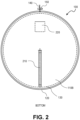
- FIG. 2 is a bottom view of an exemplary three-way convertible containment device 100 in a mat configuration, consistent with embodiments of the invention.
- base 110 includes a bottom surface or layer 110B.
- bottom surface layer 110B of base 110 may be formed of a heavyweight flexible material, such as 10oz cotton denim fabric or ballistic nylon
- top surface 110A (not shown in FIG. 2 ) of base 110 may be formed of a flexible material better suited as a work or play surface, including materials that possess waterproof and/or stain resistant properties, such as lightweight nylon materials.
- the bottom layer 110B may include a slit or opening (not shown in FIG. 2 ), similar to the opening 1430 shown in FIG. 1 .
- an opening in the layer 110B may be in addition to, or as an alternative to, the opening 1430 in the layer 110A shown in FIG.1 .
- bottom surface 110B of base 110 includes a cord pocket 220, which may be formed of flexible material, such as various types of fabric, sewn or otherwise attached to base 110.
- cord pocket 220 may include one or more Velcro ® brand strips to secure items, in particular the cinch cord 140, inside cord pocket 220.
- buttons, snaps, zippers, or other closure means may be used to secure cinch cord 140 inside cord pocket 220.
- the dimensions of cord pocket 220 are not critical, as long as cord pocket 220 can easily store cinch cord 140, which may have a length approximately equal to the circumference or periphery length of base 110.
- cinch cord 140 comes out two openings in the envelope or channel 710 formed by lip 120 (see FIG. 7 ) at a point of the periphery of base 110 that is near the opening of cord pocket 220.
- cinch cord 140 may come out of openings in the envelope or channel 710 formed by lip 120 at two points of the periphery of base 110, such as two points on a diameter of base 110.
- Such an embodiment may include two cord pockets 220 positioned near the two points on the diameter of base 110 where cinch cord 140 emerges from the envelope of lip 120.
- lip 120 may be formed of two separate pieces, each having a length approximately one-half the circumference of base 110, or less (e.g., up to about 15% less), and cinch cord 140 may include two cord locks 150 and/or there may be two cinch cords 140.
- cinch cord(s) 140 comes out of openings in the envelope or channel formed by lip 120 at more than two points of the periphery of base 110 are also possible.
- Carrying strap 210 is also attached to bottom surface 110B.
- Carrying strap 210 may be formed of strong, flexible material, such as various types of fabric, which are sewn, riveted, or otherwise attached to base 110.
- Carrying strap 210 may be used to lift and carry convertible containment device 100, especially when convertible containment device 100 is in a bag-like luggage configuration.
- carrying strap 210 may be constructed of nylon webbing material, and may include a padded section.
- the dimensions, the attachment points, the number, and even the presence, of carrying strap 210 are not critical. As an example, in an embodiment where the diameter of base 110 is about 60 inches, the length of carrying strap 210 may be about 28 or 29 inches.
- a relatively short (e.g., 8 inch or hand sized) carrying strap may be used, having a first attachment point on bottom surface 110B of base 110 and the other attachment point opposite the first attachment point on top surface 110B of base 110.
- two separate carrying straps 210 may be provided, configured such that one strap may go over each shoulder of a person, and convertible containment device 100 may be transported as a backpack or knapsack.
- FIG. 3 is a side view of an exemplary three-way convertible containment device 100 in a mat configuration, consistent with embodiments of the invention.
- base 110 is deployed on a horizontal surface
- lip 120 is standing substantially perpendicular to base 110 and is substantially vertical.
- lip 120 stands at a uniform height throughout its length.
- lip 120 may not stand to a uniform height, as portions of lip 120 may flex, sag, or flop over to some degree (e.g., as a function of the flexibility of the material used to form lip 120), reducing the deployed height in localized sections of lip 120.
- cinch cord 140 is depicted as running inside a cavity or envelope formed by the flexible material of lip 120, up to a point where cinch cord 140 emerges from the cavity, close to where cord lock 150 is deployed in this example.
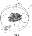
- FIG. 4 is a perspective view of an exemplary three-way convertible containment device 100 in a mat configuration, consistent with embodiments of the invention.
- items 410 are contained on the top surface 110A of base 110 by the lip 120 which rises substantially perpendicular to base 110.
- the height to which lip 120 rises above base 110 may vary at different points around the circumference of base 110, as lip 120 flexes, sags, or flops over.
- the maximum height of lip 120 is 3.5 inches
- some portions of lip 120 may sag to a height of about 1.5 to 2 inches, while other portions stand at about 3.5 inches.
- convertible containment device 100 is opened or laid out on a horizontal surface to form a mat or work/play surface having a surrounding containment wall (lip 120).
- a user may easily spread out items 410, (e.g., various parts; pieces; toys; tools; balls; sporting equipment; knitting equipment; medical tools, supplies, and devices; electronic accessories and devices; cosmetics; travel items; fasteners; camping supplies; military supplies (e.g., stop-the-bleed kit, opioid overdose kit, and IFAK (individual first aid kit), survival kit); scuba-diving accessories, emergency survival items, etc.) on the upper surface or layer 110A of base 110, where they can be easily seen and utilized, for example to play or work with as an entire set.
- items 410 e.g., various parts; pieces; toys; tools; balls; sporting equipment; knitting equipment; medical tools, supplies, and devices; electronic accessories and devices; cosmetics; travel items; fasteners; camping supplies; military supplies (e.g., stop-the-bleed kit, opioid overdose kit, and
- lip 120 stops items 410 from being pushed off of upper surface 110A of base 110 during use of items 410, which later enables a user to quickly and efficiently clean up and store items 410 by converting convertible containment device 100 into the closed, bag-like configuration while items 410 are contained on upper surface 110A of base 110.
- Examples of activities involving numerous items 410 include traveling (e.g., items like cosmetics, toiletries, money, electronics, accessories, etc.), playing, repairing and other work, etc.
- Examples of items connected to playing include: Lego ® brand building blocks, Lincoln Log ® brand building sticks, Kynex ® brand building blocks, Duplo ® brand building blocks, Matchbox ® brand toy cars, Hot Wheels ® brand toy cars, Polly Pockets ® brand figures, American Girl ® brand doll sets, Barbie ® brand dolls, Squinkies ® brand figures, Playmobil ® brand figures, wooden building blocks, action figures, Star Wars ® brand action figures, Thomas and Friends ® brand train toys, Littlest Pet Shop ® brand toys, My Little Pony ® brand toys, beads, crafts and art supplies, clay modeling, board games, train sets, dolls and doll accessories, stuffed animals, marbles, jacks, puzzles, building sticks, Play-Doh ® brand modeling clays, etc.
- Examples of items connected to repairing and other work include:
- the opening 1430 in the layer 110A of the base 110 is closed, such that it appears as a line or seam in the embodiment shown.
- the opening 1430 may be implemented as a vent or a slit or the like, where the material on each side of the opening may not overlap.
- the opening 1430 may be implemented as a placket or the like, where the material on each side of the opening overlaps with each.
- Some embodiments may employ fasteners for opening and securely closing the opening 1430.
- Arrows 420 represent the motion of lip 120 when convertible containment device 100 is converted from the mat configuration to the bag configuration.
- a user may vertically lift and pull cinch cord 140 while items 410 are on top surface 110A of base 110, such that in the bag configuration top surface 110A becomes part of the inner surface of the bag, while bottom surface 110B becomes part of the outer surface of the bag.
- the lifting and pulling of cinch cord 140 causes the lip 120 and the peripheral edge of base 110 to raise and draw together as the portion of cinch cord 140 inside lip 120 becomes smaller, which forms convertible containment device 100 into a bag-like container or piece of luggage with items 410 inside.
- cord lock 150 to lock in a position near lip 120, which prevents cinch cord 140 from entering the envelope formed by lip 120 and clamps shut the bag formed by convertible containment device 100.
- the material that forms the lip 120, (and which envelopes cinch cord 140) may be any material that is flexible, thin, and non-binding to a degree that allows the material to be drawn together in a manner that leaves little or no opening in the bag when the cinch cord 140 is tightened to a large degree-i.e., when cinch cord 140 is used as a draw string to force lip 120 into a smaller annular shape.
- 1.9 oz., calendared, rip-stop nylon material provides the appropriate characteristics of flexibility, thinness, and non-bindingness for lip 120.
- Other materials with similar properties may also be used within the scope of the invention.
- the exemplary embodiment shown in FIG. 4 also includes a carrying strap 215, which may be formed of strong, flexible material, such as various types of fabric, and which is sewn, riveted, or otherwise attached to base 110.
- carrying strap 215 may be constructed of nylon webbing material.
- the embodiment shown employs carrying strap 215 having a first attachment point (not shown) on bottom surface 110B of base 110 and a second attachment point opposite the first attachment point on top surface 110B of base 110.
- carrying strap 215 forms a loop and passes through an annular passage (e.g., annular passage 510 of FIG. 5 ) when convertible containment device 100 is in the bag configuration.
- the illustrated implementation of carrying strap 215 may be preferable to the implementation of carrying strap 210 ( FIG. 2 ) where the length of carrying strap 210 is shorter than the length required to pass a person's arm through carrying strap 210 and comfortably sling convertible containment device 100 in the bag configuration over the person's shoulder.
- the lip may include several magnets (e.g., cylindrical, permanent, rare-earth magnets of from about 1/16 to about 1 inch in diameter and about 1/16 to about 1 ⁇ 2 inch in height) that are sewn into or otherwise attached to or contained in specific areas of the lip 120, for example, inside of the envelope.
- the lip 120 may be gathered by hand to convert the device 100 from the mat configuration to the bag configuration, and the magnets may attract to each other to keep the lip 120 in a gathered position so that the device remains in the bag configuration, similar to that shown in FIG. 5 .
- the lip 120 may be fitted and wired with electromagnets, a power source, and a switch.
- the lip 120 may be gathered by hand to convert the device 100 from the mat configuration to the bag configuration, and the electromagnets may be switched on to attract to each other to keep the lip 120 in a gathered position so that the device remains in the bag configuration.
- the bag may be automatically opened and at least partially converted back to the mat configuration by switching off the magnets and allowing gravity to pull the device into a position where the base 110 is partially or largely flat.
- Still other embodiments may have an electromagnetic closing mechanism in the lip 120, which, when switch on, at least partially gathers the lip 120 and at least partially reconfigures the device 100 into the bag configuration.
- FIG. 5 is a side view of an exemplary three-way convertible containment device 100 in a bag configuration with the device 100 resting on flat surface, consistent with embodiments of the invention.
- cinch cord 140 has been drawn to place convertible containment device 100 in a bag or luggage configuration and to essentially close or fully close an annular passage 510.
- bottom surface layer 110B of base 110 forms the lower portion of the outside of the bag or luggage.
- a user may slide cord lock 150 to a position adjacent to lip 120 and adjacent to closed annular passage 510 (as shown), and secure cord lock 150 at that position. Locked cord lock 150 prevents any additional length of cinch cord 140 from entering the envelope formed by lip 120 and increasing the diameter or opening size of annular passage 510.
- the tightening of cinch cord 140 draws together or gathers together the thin, flexible, non-binding (e.g., slippery) material of lip 120 so that annular passage 510 is essentially closed, at least to a degree that does not allow items 410 to pass through annular passage 510.
- the drawstring or cord 140 is pulled very tightly the annular passage becomes completely closed.
- a thin, flexible, non-binding material is preferred for lip 120 because such material will gather, compact, and/or fold upon itself inside the loop formed by tightened cinch cord 140 and completely, or nearly completely, fill in and close annular passage 510, thus preventing small items 410 that are inside convertible containment device 100 from escaping from inside the bag configuration shown in FIG. 5 .
- 1.9 oz., calendared, rip-stop nylon cloth provides the appropriate characteristics of flexibility, thinness, and non-bindingness for lip 120.
- Similar suitable materials may include 1.0 ounce nylon cloth; 1.1 ounce silicone impregnated nylon cloth; 3 ⁇ 4 ounce nylon spinnaker cloth, 1.1 ounce nylon parachute cloth, paraglider fabric, satin, and the like. Other materials with similar properties may also be used within the scope of the invention.
- Thicker, heavier materials such as denim, canvas, large denier nylon, and the like, are not preferred for some embodiments of lip 120 because such materials will not gather, compact, and/or fold upon themselves sufficiently to completely, or nearly completely, close annular passage 510 when cinched into a relatively small annular shape by cinch cord 140.
- the device 100 in the drawstring bag configuration is approximately in the shape of a hemisphere.
- the device is resting on a flat surface, such as a table top, which imparts a flat side to the device 100, and creates the hemispherical shape, due to the flexibility of the materials forming the base 110 and the lip 120.
- a flat surface such as a table top
- the device assumes a generally spherical shape when in the drawstring bag configuration while not resting on a flat surface and/or if not being affected by gravity.
- FIG. 6 is a top view of an exemplary convertible containment device 100 in a bag configuration, consistent with embodiments of the invention.
- cinch cord 140 has been drawn to place convertible containment device 100 in a bag or luggage configuration and to essentially close annular passage 510.
- cord lock 150 is not shown, for clarity of illustration.
- cord lock 150 would be positioned adjacent to lip 120 and adjacent to closed annular passage 510, locking annular passage 510 in a drawn-closed position.
- the length of cinch cord 140 that was pulled out of the envelope formed by lip 120 to close convertible containment device 100 is stored inside of cord pocket 220.
- the tightened cinch cord compresses the material of lip 120 inside annular passage 510 formed by the portion of cinch cord 140 that remains within the passage or envelope 710 formed in lip 120, which blocks and closes annular passage 510.
- the loose portion of cinch cord 140 may be placed completely inside cord pocket 220, and cord pocket 220 may be fastened closed using a Velcro ® brand strip, button, snap, zipper, flap, or other closing means.
- FIG. 6 also illustrates that carrying strap 210, which is attached to bottom surface 110B of base 110, is available for a user to grasp when convertible containment device 100 is in a bag or luggage configuration.
- a user may, for example, place carrying strap 210 over their shoulder to transport convertible containment device 100, with items 410 inside, to another location.
- FIG. 7 is a detailed perspective view of an exemplary containment lip 120 and drawstring 140 of a convertible containment device 100, consistent with embodiments of the invention.
- lip 120 may be made of a flexible material that is doubled over or folded over and attached to base 110 in a manner that forms a hollow cavity, channel, or envelope 710, having openings at each end.
- cinch cord 140 may be run through envelope 710, so that cinch cord 140 surrounds base 110 when convertible containment device 100 is open and laid out in the mat configuration, and so that cinch cord 140 may be drawn or slid through and out of openings in envelope 710 to form a bag with an annular passage 510.
- envelope 710 may be divided into two or more smaller envelopes, for example by stitching or otherwise lengthwise joining together the walls of envelope 710.
- cinch cord 140 may pass through one of the smaller envelopes.
- cinch cord 140 may pass through the lower small envelope, which is adjacent to base 110, in order to enhance the standing up of lip 120 when convertible containment device 100 is in the mat configuration.
- cinch cord 140 may pass through the middle small envelope, which is removed from base 110 by a lower envelope, in order to enhance the cinching and closing of annular passage 510 when convertible containment device 100 is in the bag or luggage configuration.
- envelope 710 may be empty, or envelope 710 may be nonexistent for embodiments where the material forming lip 120 is not folded over.
- cinch cord 140 may be attached to the outside of lip 120 using loops (e.g., similar to belt loops) or other means of slidable attachment that allows lip 120 to be cinched closed in the bag configuration.
- cinch cord 140 may be replaced by another closing mechanism, such as a clamp (e.g., similar to one half of a pair of handcuffs, similar to a tightening or ratcheting strap as found on a ski boot, or similar to a locking wood clamp, and the like) that is clamped on the outside of, and squeezes together, the folds of lip 120 after a user has gathered the folds together by hand to form a bag configuration.
- the clamp may be stored in outside pocket 220 when convertible containment device 100 is in the mat configuration.
- FIG. 8 is a view of exemplary components fpr a three-way convertible containment device, consistent with embodiments of the invention.
- base 110 has a circular shape with a diameter D and a circumference C.
- the embodiment of a base 110 shown in FIG. 8 includes two components, pieces, or layers 110B and 110Z, which are stacked on each other when assembled.
- the diameter of base 110 may be in the range of about 6 inches to about 120 inches or larger, including embodiments of 18 inches, 20 inches, 22 inches, and 60 inches.
- Layer 110Z of the base 110 that includes an opening 1430, which allows access to the space between layer 110B and layer 110Z, and which may be formed or implemented in different ways in different embodiments.
- the layer 110Z includes a hole or slit 1430 in a single piece of material that forms the layer 110Z.
- the layer 110Z may be formed by joining or attaching (e.g., using stitches) multiple pieces of material (e.g., fabric) together in a manner that leaves an opening similar to opening 1430.
- two or more pieces of material may be stitched together to form a placket, vent, or the like which allows access to the space between layer 110B and layer 110Z.
- the opening 1430 may be fitted with one or more fastener, such as a zipper 180, buttons, a hook and loop strip(s), or the like, to make the opening 1430 sealable and unsealable.
- fastener such as a zipper 180, buttons, a hook and loop strip(s), or the like
- FIG 8 shows the opening 1430 spanning almost the entire diameter of the layer 110Z of the base 110 (e.g., spanning greater than 90% of the diameter), other embodiments may include an opening 1430 that is smaller, such as an opening 1430 that has a length that is from about 15% to about 89% of the longest dimension (e.g., the diameter for a circle) of the base 110.
- lip 120 has a folded-over rectangular shape with a length approximately equal to the circumference C of base 110.
- the approximately length of lip 120 may be a longer or shorter than C.
- variations from length C may be needed to facilitate attaching lip 120 along the periphery of base 110, or to facilitate multiple openings for multiple cinch cords or drawstrings, among other things.
- lip 120 also has a height dimension H.
- the height of lip 120 may be in the range of about 1 inch to about 5 inches or larger, including embodiments of 1.5 inches and 3.5 inches.
- making the length of lip 120 approximately equal to C, and/or attaching lip 120 to base 110 so that the effective length of lip 120, without counting overlap, is approximately equal to C creates a structure that urges lip 120 to rise or stand up in a vertical direction when base 120 is spread out flat on a horizontal surface, such as a floor or table.
- lip 120 may be made of more than one piece, each piece having a length that together making the overall length of lip 120 approximately equal to C. Such embodiments may have multiple openings in the envelope 710, from which a cinch cord 140 may emerge.
- the length of lip 120 may be slightly greater than C while still being approximately equal, for example up to about 5% greater than C (such as 1%, 2%, 3% or 4% greater), or from about one-half inch to about one inch greater than C, such that the ends of lip 120 overlap to some degree when attached to base 110, reducing or eliminating space(s) between the ends of lip 120 when attached to base 110.
- the length of lip 120 may be less than C while still being approximately equal, for example up to about 20% less than C, (such as 1%, 2%, 3%, 5%, 7%, 10%, 14%, 17%, or 22% less), or from about one-quarter inch to about six inches shorter than C, such that the ends of lip 120 are separated to some degree when attached to base 110, leaving space(s) between the ends of lip 120 when attached to base 110.
- FIG. 8 also shows one example of an optional dividing line 1405 on the lip 120, wherein the dividing line 1405 indicates where the lip 120 could be cut into, divided into, or implemented as two separate pieces.
- the pieces may be attached to the base 110 with a space or gap between them to allow access to one or more cords 140 and the total length of the pieces may be less than the circumference C of the base 110.
- the total length of the pieces of the lip 120 may be approximately equal to the circumference C of the base 110, as shown.
- the total length of the pieces of the lip 120 may be from about 5% more about 20% less than the circumference C of the base 110.
- other embodiments may have more than one dividing line 1405, such that the lip 120 could be cut into, divided into, or implemented as three or more separate pieces, which may be attached to the base 110 with or without spaces between them, and/or which may be sewn together to form longer envelopes.
- FIG. 8 also shows an example of material used to make the wall of a large volume, cylindrical-shaped bag 1305.
- the material for the bag 1305 has a rectangular shape with a length approximately equal to the circumference C of base 110.
- the length of the material for the bag 1305 may be a longer or shorter than C.
- variations from length C may be needed to facilitate attaching the bag 1305 to the base 110, among other things. For example, variations from length C may depend on how close the length edge of the bag 1305 is attached to the periphery of the base 110.
- the material for the bag 1305 may be of approximately length C, or a little longer, (e.g., up to +5% longer), if attached at or near the periphery, or it may be less than length C, (e.g., up to -10% shorter), in embodiments where it is attached inboard of the periphery.
- the material for the bag 1305 also has a height dimension H2.
- the height H2 of the bag 1305 may be in the range of about 4 inches to about 48 inches or larger, including embodiments of 12 inches, 15 inches, 16 inches, 18 inches, and 27 inches, among others.
- FIG. 8 is described using circular base 110 as an example, corresponding principles apply when base 110 is shaped as an ellipse that is not a circle, an oval, a polygon, or the like. Further, embodiments that use a circular base 110 as shown in the example of FIG.
- the bag 1305 is formed of two pieces, portions, or panels of material: a first, left piece 1410 and a second, right piece 1411, which are attached or joined together, for example using stitches of thread.
- the bag wall 1305 may be formed of a single piece of material, or the bag wall 1305 may be formed of more than two pieces of material that are joined together.
- the overall shape of the bag 1305, whether or not composed of multiple pieces 1410, 1411, may be trapezoidal instead of rectangular as shown in FIG. 8 , such that when deployed in the approximately cylindrical bag configuration (e.g., for use as a shopping bag), the bag has the approximate form of a truncated cone or an inverted truncated cone.
- the left edge 1420 of the material of the bag 1305 is attached or joined to the right edge 1421 of the material of the bag 1305 (e.g., by stitching or adhesive or the like) and the bottom edge 1423 of the material of the bag 1305 is attached or joined to the base 110, for example, at or near the periphery or perimeter of the base 110.
- the top edge 1424 of the bag 130 forms the rim of the opening of the approximately cylindrical bag when the device 100, 1100 is in the approximately cylindrical bag configuration.
- the bottom edge 1423 of the material of the bag 1305 may attached or joined inboard from or inside the periphery or perimeter of the base 110, such as from about one-quarter inch to about six inches inboard of the perimeter of the base 110 or from about 1/15 to about 1 ⁇ 4 of the base's diameter inboard.
- the diameter of a circular base 110 is 20 inches
- the bottom edge 1423 of the bag 1305 may be attached two inches (or 1/10 of the base's diameter) inboard of the base's perimeter, such that the circular bottom of the cylindrical-shaped shopping bag has a diameter of 16 inches.
- the length of the bottom edge 1423 of the bag 1305 may be less than the circumference C of the base 110.
- the bag 1305 may be formed of one layer of material (as shown) or may be formed of two or more layers of material, which may be attached to each other by stitches, adhesive, or the like.
- the three-way convertible containment device may include other components that are not shown in the example of FIG. 8 , such as a cord(s), a cord lock(s), a pocket(s), a handle(s), a device carrying pouch, etc.
- FIG. 9 is a detailed cut-away perspective view of an exemplary attachment between a containment lip 120 and a layer of a base 110 of a convertible containment device 100, consistent with embodiments of the invention.
- lip 120 is attached to base layer 110 using gathers or pleats 810 secured by stitches 130.
- pleats 810 allow the straight edge of lip 120 to be attached to the curved or multi-angled periphery of base 110, and provide structure and static forces which urge lip 120 to rise or stand approximately perpendicular to base 110.
- the layer of base 110 is folded over at the periphery to provide a more substantial anchor for stitches 130.
- base 110 may not include this fold.
- this illustration shows only a single layer or piece of material for base 110.
- base 110 may be formed of multiple pieces or layers.
- a second layer of base material may be placed over pleats 810 before stitching, such that pleats 810 are sandwiched between two base pieces or layers.
- a similar sandwiching arrangement that includes a third piece of padding or other material may be used to form base 110.
- Attachment means other than stitches 130, such as glue, heat welding, rivets, etc. are within the scope of the invention.
- serge stitching or overlocking stitching may be used to attach lip 120 to base 110.
- base 110 and lip 120 may be formed of a single piece of thin flexible material (not shown).
- the folded over edge of the single piece may be formed into pleats or gathers, similar to pleats 810, so as to urge the portion of the single piece forming the envelope to rise approximately perpendicular to the portion of the single piece forming the base.
- pleats 810 may gather in a lesser amount of material that is insufficient to fold over as shown, but which instead forms a smaller single fold in a substantially perpendicular orientation to base 110 or forms ripples in the lip material, where the ripples do not include folds.
- These single-fold and ripple implementations may be more desirable in embodiments where base 110 has a diameter of about two feet or larger. Other implementations are possible within the scope of the invention.
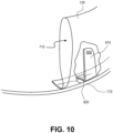
- FIG 10 is a detailed cut away perspective view of an exemplary containment lip 120 with a support member 900 for a convertible containment device 100, consistent with embodiments of the invention.
- envelope 710 formed by lip 120 contains a support member 900 that cause at least a portion of lip 120 to stand up from or rise approximately perpendicular to base 110.
- support member 900 may be "L" shaped, with a first leg 920 of support member 900 sewn or otherwise attached to base 110 such that a second leg 910 of support member 900 stands substantially perpendicular to the base 110, holding up at least a portion of lip 120.
- the length of the second leg 910 may be approximately half the height of lip 120, or shorter, to avoid interfering with the gathering of the top edge of lip 120 when cinch cord 140 (not shown) is tightened to close convertible containment device 100 into a bag configuration.
- support member 900 may be formed of a somewhat stiff yet pliable material, such as vinyl plastic or the like. In other embodiments, support member 900 may be formed of other materials that provide structure to cause lip 120 to stand up, such as wire, sections of thick fabric (e.g., ballistic nylon), leather, and the like.
- support members 900 may be placed within envelope 710 at spaced intervals (not shown) around the periphery of base 110.
- support members 900 may be spaced from about 6 inches to about 18 inches apart around the periphery of base 110.
- the distance between support members 900 may be at least 8 inches to avoid interfering with the gathering of lip 120 when cinch cord 140 (not shown) is tightened to close convertible containment device 100 into a bag configuration.
- One advantage, among several, of the disclosed convertible containment device is that various embodiments provide an easily storable and transportable shoulder satchel, bag, or knapsack that converts into a mat and that is structured to securely contain large and small items both in the open, mat position and in the closed bag/satchel/knapsack position.
- Various embodiments allow users, including children of appropriate age, to quickly and efficiently clean up pieces, parts, components, etc. that are laid out and/or used on the open mat.
- Various embodiments also assist a Warfighter in Expeditionary Advanced Base Operation (EABO) efforts, such as by enabling rapid deployment, containment, and packing of Warfighter items and materials.
- EABO Expeditionary Advanced Base Operation
- FIG. 10 shows only a single layer or piece of material for base 110, but in various embodiments as described herein, base 110 may be formed of multiple pieces or layers.
- FIG. 11 is a top view of an example of a three-way convertible containment device 1100 in a mat configuration, consistent with embodiments of the invention.
- the three-way convertible containment device 1100 is spread out in a mat or work surface configuration and shows the top side or top layer 110Z of the base 110.
- the top layer 110Z of the base 110 includes a fastener or fastening means, in this example a zipper 180, for an opening 1430 in the layer 110Z, which enables a user to seal and unseal (e.g., fasten and unfasten) the opening 1430.
- the zipper 180 has two pull tabs; one is shown in FIG.
- the layer 110Z may also be referred to as the zipper layer 110Z in this embodiment.
- the base 110 may be elliptical, circular (as shown), or oval in shape, or approximations thereof.
- base 110 may be in the shape of a polygon, such as an equilateral, cyclic polygon having four or more sides, e.g., a square, a hexagon, an octagon, etc., or an irregular polygon.
- Other embodiments of base 110 may be in the shape of a many-sided polygon that approximates an elliptical or oval shape, e.g., a dodecagon, an elongated dodecagon shape, etc.
- the diameter or longest dimension of base 110 may be in the range of about 6 inches to about 120 inches or larger, including embodiments of 12 inches, 13 inches, 16 inches, 18 inches, 20 inches, 22 inches, 24 inches, and 60 inches, among others.
- base 110 may be formed of two or more pieces or layers of flexible material, such as denim, suede, leather, velvet, canvas, cotton twill, polyester including large denier polyester, nylon including large denier nylon, ballistic nylon, ripstop nylon, nylon mesh fabric, sail oxford ripstop nylon, Cordura TM brand fabric, packcloth, recycled material, or the like.
- base 110, or one or more layers thereof may be formed of a lightweight flexible material, such as 1.9 oz calendared rip-stop nylon material, polyester, microfiber fabric, taffeta fabric, or the like.
- one or both of the zipper layer 110Z and the bottom layer or surface 110B see FIG.
- base 110 may be formed of a lightweight flexible material, such as 1.9 oz calendared rip-stop nylon or polyester material, to provide a work or play surface having specific desired qualities, such as being waterproof, stain resistant, pleasant to touch, colorful, easily able to custom print, etc.
- bottom surface 110B (not shown in FIG. 11 ) of base 110 may be formed of a relatively heavyweight flexible material, such as 10oz cotton denim fabric or ballistic nylon (e.g., 1000 denier ballistic nylon) or the like.
- the layer 110Z of the base 110 may be formed of two (or more) pieces 111, 112 of flexible material that are configured to form an opening 1430, which is closable by the zipper 180; while in other embodiments, the layer 110Z may be single piece of material with a slit or the like in it, which forms an opening 1430 that accommodates the zipper 180.
- the zipper 180 is just one type of fastener that may be used.
- each of the pieces 111, 112 of the zipper layer 110Z is approximately the shape of a semicircular.
- the pieces 111, 112 may both be smaller than a semicircular (i.e., may be less than half the size of the circular base 110), which may be desirable to provide space or gap, which may be taken up by a zipper 180 in some embodiments.
- one piece 111 may be larger than a semicircle, and the other piece 112 may be smaller than, larger than, or the same size as a semicircle.
- the piece 111 may overlap the piece 112, for example in placket-like arrangement, and a fastener other than a zipper 180 (e.g., button(s), snap(s), hook and loop strip(s), etc.), may be employed to seal and unseal the opening 1430 between the pieces 111, 112.
- a fastener other than a zipper 180 e.g., button(s), snap(s), hook and loop strip(s), etc.
- no fastener at all may be employed.
- the pieces 111, 112 of the layer 110Z may be in the form of half, or approximately half of the base's shape; for example, one-half of an ellipse, one-half of a polygon, (e.g., one-half of a hexagon), and the like.
- one piece 111 may be larger than half of the base shape, and the other piece 112 may be smaller than, larger than, or the same size as one half of the base shape.
- the separation, gap, slit, or opening 1430 in the base layer 110Z may be off center or not in the middle of the base 110, such that the pieces 111, 112 are not the same size and/or shape.
- the opening 1430 and/or the zipper 180 may be curved or otherwise non-linear.
- the layer 110Z of the base 110 may be formed of more than the two pieces 111, 112, shown in the example of FIG.11 , and some of those pieces may be joined to each other by stitching or the like, and/or a fastener, such as the zipper 180.
- the layer 110Z (and/or the bottom layer 110B, or both) may have one (or more) opening 1430 (e.g., a slit, vent, placket or the like), which may or may not include a fastening or closing means or device, (e.g., a zipper 180, hook and loop strips, buttons, snaps, or the like).
- the opening 1430 allows access to the space or area in the base 110 between the layer 110Z and the layer 110B, such that the cylindrical-shaped bag 1305 may be placed or folded into the space between the layers of the base 110, e.g., when the cylindrical-shaped bag 1305 is not in use.
- a lip 120 is attached to the perimeter of base 110 in a manner that causes at least a portion of lip 120 to stand substantially perpendicular to base 110 when base 110 is spread out on a substantially horizontal surface.
- the lip 120 forms a wall or barrier around the zipper layer 110Z, and acts to contains any items, parts, or pieces placed on top surface 110A while a user utilizes the items, parts, or pieces. See, for example FIGs. 3 and 4 .
- lip 120 stands up substantially perpendicular to base 110 due at least in part to the configuration of lip 120, e.g., its dimensions, such as vertical height above horizontal base 110, and its connection to the circumference or periphery of the base 110, and its folded form in certain embodiments.
- lip 120 stands up substantially perpendicular to base 110 due at least in part to its fabrication from lightweight flexible material, such as 1.9 oz calendared rip-stop nylon material or a light polyester material, including its fabrication from a material that is more flexible and lower in weight and density compared to a thicker, more rigid material (e.g., 10 oz. denim) that forms base 110.
- lip 120 stands up substantially perpendicular to base 110 due at least in part to its method or implementation of attachment to base 110. In some embodiments, lip 120 stands up substantially perpendicular to base 110 due at least in part to the elliptical, oval, or polygonal shape of base 110. In some embodiments, lip 120 stands up substantially perpendicular to base 110 due at least in part to the presence of a particular length of string or cord inside an envelope formed by lip 120. In some embodiments, lip 120 stands up substantially perpendicular to base 110 due at least in part to a separate stiffening structure such as perpendicular support members attached to the base 110 and situated inside an envelope formed by lip 120.
- lip 120 may be attached to base 110 by stitches 130.
- lip 120 may be configured (e.g., folded over) to form a channel or envelope through which a cinch cord 140 may pass.
- cinch cord 140 may be pulled to change convertible containment device 1100 from the open flat configuration shown into a closed bag-like configuration (as shown in FIG. 5 ).
- cinch cord 140 comes out of adjacent openings of the envelope formed by lip 120 at a single point of the periphery of base 110.
- cinch cord 140 may also pass through a cord lock 150, which may be adjustably employed to clamp and maintain convertible containment device 1100 in a closed bag-like configuration.
- cinch cord 140 may come out of the multiple openings and may have multiple cord locks 150, and/or there may be two or more cinch cords 140, each having a cord lock 150.
- cinch cord 140 may be constructed of 3 mm or 5 mm climbing cord.
- the zipper layer 110Z of base 110 includes pockets 160, which may be formed of flexible material, such as various types of fabric, including for example see-through vinyl plastic, that is sewn or otherwise attached to base 110. Pockets 160 may be used to contain and separate chosen items from other items contained in convertible containment device 1100, especially when convertible containment device 1100 is in a bag-like luggage configuration. In the embodiment shown, pockets 160 may use zippers 170 to open and close the pocket opening. In other embodiments, buttons, Velcro ® brand hook and loop strips or other closure means may be used to prevent any contents of pockets 160 from leaving interior pockets 160. The dimensions, and even the presence, of pockets 160 are not critical. As an example, in an embodiment where the diameter of base 110 is about 60 inches, the dimensions of pockets 160 may be about 6 inches by about 14 inches.
- the layer 110Z of base 110 includes an opening 1430, (in this instance fastened by the zipper 180), that provides access to the space between the zipper layer 110Z and the bottom surface or layer 110B of the base 110.
- the space between the zipper layer 110Z and the bottom surface 110B may be used to contain additional flexible components (e.g., components made of fabric or a like material) that can be configured to form an approximately cylindrical bag out of the containment device 1100, while maintaining the structure and ability to also convert the device into a containment mat configuration (e.g. as shown in FIG.4 ) and into an approximately spherical, drawstring bag configuration (e.g. as shown in FIG. 5 ).
- additional flexible components e.g., components made of fabric or a like material
- the opening 1430 and the zipper 180 may be included in the bottom surface 110B of the base 110. Still other embodiments may include openings 1430 in both the layer 110Z and the bottom layer 110B of the base 110. As previously noted, the opening(s) 1430 may be closable by means other than a zipper 180, including, for example, devices such as a hook and loop strip, a plastic zip lock, buttons and button holes, and the like; or there may be no means or device included to close the opening 1430, in some embodiments.
- FIG. 12 is a perspective view of a three-way convertible containment device 1100, 100 in a mat configuration, consistent with embodiments of the invention.
- the zipper 180 that opens and closes the opening 1430 in the layer 110Z of the base 110 is in the closed or zipped-up position.
- items 410 are contained on the zipper layer 110Z of base 110 by the lip 120 which rises substantially perpendicular to base 110.
- the height to which lip 120 rises above base 110 may vary at different points around the circumference of base 110, as lip 120 flexes, sags, or flops over.
- some portions of lip 120 may sag to a height of about 1.5 to 2 inches; and in an embodiment where the maximum height of lip 120 is 1.5 inches, some portions of lip 120 may sag to a height of about 0.5 to 1 inch.
- this view is similar to that described above with respect to FIG. 4 .
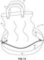
- FIG. 13 is a perspective view of an example of the three-way convertible containment device 1100, 100 showing the partial deployment of a bag 1305, which was flattened or folded and tucked or otherwise stored between the zipper layer 110Z of the base 110 and the bottom surface layer 110B of the base 110 when the zipper 180 was closed, as shown in FIGs. 11 and 12 .
- the wall of the bag 1305 may be formed of one, two or more pieces or layers of flexible material, such as canvas, cotton fabric, polyester, nylon, ballistic nylon, ripstop nylon, ripstop polyester, mesh or net fabric (e.g., nylon mesh), packcloth, non-woven material, recycled material, and the like.
- the approximately cylindrical bag 1305 may be formed of a lightweight flexible material, such as 1.9 oz calendared rip-stop nylon material or fabric, microfiber fabric, nonwoven plastic material, taffeta fabric, 1.9 oz polyester fabric, or the like.
- one end (e.g., the bottom edge 1423) of the wall of the bag 1305 is attached to the base 110, for example, using stitching, adhesive, or the like, preferably at, along, or near the periphery or perimeter of the base 110.
- the base 110 is circular in shape
- the wall of the bag 1305 and the base 110 form a cylindrical shape, where one end of the cylinder is closed by the base 110, and the other end of the cylinder is open such that items can be placed inside the space formed by the wall of the bag 305 and the base 110.
- the volume of the bag 305 is typically substantially larger, (e.g., 1.5 times larger, two times larger, three times larger, five time larger, ten times larger, 15 times larger, or more) than the "drawstring" bag formed by pulling the cinch cord 140 to form a spherical-shaped bag as shown in FIG. 5 .
- the base 110 is not circular, but is instead ovoid, oval, non-circular elliptical, or polygonal in shape, (such as an equilateral, cyclic polygon having six or more sides, e.g., a hexagon, an octagon, a dodecagon, etc.), then the wall of the bag 1305 and the base 110 will not form a bag that is exactly cylindrical in shape, but will instead form a bag that is "approximately cylindrical” in shape or "cylindrical-shaped", which is how those terms are used herein.
- the terms “approximately cylindrical” and “cylindrical-shaped” include exactly cylindrical in shape, and even cuboid in shape (for the case of a square base), and other shapes in between those two, as used herein.
- an "approximately cylindrical bag” as used herein may actually be cuboid in shape for an embodiment where the base 110 is a square.
- the bag 1305 includes two handles 1310 and 1315.
- the handles 1310 and 1315 may be separate components or pieces that are attached (e.g., by stitches) to the wall of the approximately cylindrical bag 1305, as shown in FIG. 13 .
- the handles 1310 and 1315 may be formed of the same or similar materials as any other part or component of the three-way convertible containment device 1100, 100, such as, for example, nylon fabric or polyester fabric.
- each handle may be made from one or more strip of material that has a width in the range of approximately two inches, +/one inch, and that has a length in the range of approximately four inches to 48 inches.
- each handle may be made of two rectangular strips of material that are sewn together in 2 layers and that have dimensions of two inches wide and 18 inches long.
- the handles may instead be former by integral holes or openings in the material of the wall of the bag 1305 (not shown).
- Yet other embodiments may not have handles.
- Still other embodiments may include a drawstring (not shown) around the top of the bag 1305, where a hem at the top of the 1305 forms a channel or envelope for the drawstring.
- magnets may be used as a closing means for the top of the bag 1305.
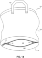
- FIG. 14 is a perspective view illustrating the side and bottom of an example of the three-way convertible containment device 1100, 100 that is deployed in an approximately cylindrical bag configuration, which may also be referred to as the "shopping bag” configuration.
- the bag 1305 was pulled completely out of the opening 1430 with the zipper 180, and the base 110 is turned inside out, such that the lip 120 is now in between the layers 110B and 110Z of the base 110, as shown. This places the opening 1430 with the zipper 180 on the outside of the bottom of the approximately cylindrical bag, as shown.
- the approximately cylindrical bag 1305 includes two handles, but only a single handle 1310 is visible, as the other handle 1315 is hidden in this perspective view.
- the layer 110Z of the base 110 that includes the opening 1430 and the zipper 180 is the outside bottom of the approximately cylindrical bag.
- the side of layer 110Z that is visible in the drawing is the opposite side of layer 110Z that is visible in FIG. 13 , because the base 110 has been turned inside out.
- the zipper 180 is open to show that the lip 120 is stored inside the base 110 in this configuration, but a user would likely close the zipper 180 when using the three-way convertible containment device 1100 in the cylindrical-shaped bag configuration.
- the zipper 180 is optional, and the opening 1430 may have no fastener and/or may have a placket-like design such that there is an overlap of material covering the opening 1430.
- a similar procedure as shown in FIGs. 13 and 14 may be performed in reverse to turn the containment lip 120 inside out from between the layers 110Z , 110B and place the approximately cylindrical bag 1305 in between those layers.
- the three-way convertible containment device 1100 in the approximately cylindrical bag configuration shown in FIG. 14 may be further configured such that the layer 110Z of the base 110 that includes the opening 1430 and the zipper 180 is the inside bottom of the approximately cylindrical bag. This may be done by turning inside out the approximately cylindrical bag 1305 shown in FIG. 14 .
- the space between the layers of the base 110, which is accessible via the zipper 180 is generally a good place of hold, store, or hide small items, which could include the small items (e.g., cosmetics or toys) that are contained in the containment mat configuration and/or the drawstring bag configuration.
- the hiding and security aspects of this space are enhanced when the approximately cylindrical bag is configured such that the zipper 180 is inside the approximately cylindrical bag, which makes it more difficult for a person to find and access.
- FIGs. 13 and 14 show the conversion from the containment mat configuration to the approximately cylindrical bag configuration
- the device 100, 1100 can similarly be converted from the drawstring bag configuration to the approximately cylindrical bag configuration in the same manner.
- small items that are contained in the drawstring bag would end up contained in the drawstring bag and also contained between the layers 110Z, 110B of the base 110.
- FIG. 15 is a cut-away view of a portion of the periphery of an example of a three-way convertible containment device 100, 1100 consistent with the invention. This drawing shows one possible way to attach or connect the parts to each other.
- the edges of: the bag 1305, the layer 110Z of the base 110 having the opening 1430 with the zipper 180, the folded over lip 120, and the layer 110B of the base 110 without the zipper are stacked and aligned, or approximately aligned.
- these parts may be attached by stitches or the like that pass through the parts along the line indicated by the arrows 1510, 1511.
- the edges of the parts may be covered by a seam cover 1505 before being stitched, which gives the three-way convertible containment device a more finished look and helps prevent the edges of the parts 1305, 110Z, 120, and 110B from wearing, fraying, ripping, unravelling, or the like.
- the seam cover may be formed of the same or a similar material as that used for any of the other parts.
- the orientation of the lip 120 may be reversed, such that the fold of the lip 120 is to the right of the stitch/attachment line indicated by the arrows 1510, 1511.
- the base layer 110B may include an opening 1430, which may be in addition to, or as an alternative to, the opening 1430 in the layer 110Z.
- any opening 1430 may lack a fastener(s), or it may be open and closable using a fastener, such as the zipper 180.
- a cinch cord 140 is not shown in this example, it would normally be found inside the "U" shape made by the lip 120.
- each part may be made of a flexible material or fabric, such as a polyester fabric, a nylon fabric, a nonwoven material, a plastic material, or the like.
- FIG. 15 shows each part as being approximately the same thickness, none of the drawings are to scale, and in various embodiments, the parts may be different or various thicknesses, e.g., the base layers 110Z and 110B may be formed of a thicker, heavier material than the lip 120 and/or the bag wall 1305.
- the parts 1305, 110Z, 120, and 110B may be made of the materials described previously herein.
- FIG. 15 is only one possible configuration-namely one wherein the approximately cylindrical bag 1305 is deployed with the base zipper layer 110A acting as the inside bottom of the approximately cylindrical bag 1305 and the non-zipper base layer 110B acting as the outside bottom of the approximately cylindrical bag.
- the approximately cylindrical bag 1305 could then be turned inside out and redeployed such that the non-zipper base layer 110B acts as the inside bottom of the approximately cylindrical bag 1305 and the base zipper layer 110Z acts as the outside bottom of the approximately cylindrical bag, as shown, for example, in FIG. 14 .
- the three-way convertible containment device 100, 1100 can also be converted to a different configuration than that shown in FIG.
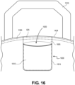
- FIG. 16 is a perspective view illustrating an example of a pouch 1600 that is attached to a section of the wall of the cylindrical-shaped bag 1305, according to an embodiment of the invention.
- the pouch 1600 may be used to store the device 100, 1100 when the device is not in use. For example, a user may fold, compress, and/or wad the device 100, 1100 into a shape that fits inside the pouch 1600.
- the pouch 1600 is formed of two pieces of material: a first pouch side 1605 and a second pouch side 1610.
- the second pouch side 1610 may be smaller than the first pouch side 1605; while in other embodiments, the sides 1605, 1610 may be approximately equal in size.
- the first pouch side 1605 and the second pouch side 1610 may be fastened together, for example using stitches 1615 or the like, in a manner that forms a pouch having an opening 1620 to its internal volume.
- the pouch 1600 may be formed of a single piece of material that is folded over and fastened along the edges, for example, using stitches.
- the size of the sides 1605 and 1610 are such that the pouch 1600 has sufficient internal volume 1620 to contain the folded up device 100, 1100.
- the size of the pouch 1600 will be dependent on the size of the device 100, 1100, which is related to the size of the base 110, the lip 120, the bag wall 1305, the handles 1310, 1315, and the like.
- the pouch may be attached at or near the top edge 1424 of the cylindrical shaped bag 1305, for example, using stitches 1625.
- the pouch 1600 is attached between the ends of one of the handles 1320 of the cylindrical shaped bag 1305.
- the pouch 1600 may be attached in a different location on the device 100, 1100, as the attachment point is not critical.
- the pouch 1600 may be separate from and not attached to the device 100, 1100.
Landscapes
- Chemical & Material Sciences (AREA)
- Engineering & Computer Science (AREA)
- Materials Engineering (AREA)
- Purses, Travelling Bags, Baskets, Or Suitcases (AREA)
Claims (12)
- Vorrichtung (100) zum Enthalten von Gegenständen, wobei die Vorrichtung umfasst:eine flexible, in etwa elliptische Basis (110), die einen Umfang aufweist und die eine erste Materialschicht (110A) und eine zweite Materialschicht (110B) umfasst, wobei die erste Materialschicht eine Öffnung (1430) beinhaltet,eine flexible Lippe, die eine Länge aufweist, die in etwa gleich einem Umfang der flexiblen, in etwa elliptischen Basis ist, wobei die flexible Lippe mindestens ein Stück von dünnem Material umfasst, das dazu ausgestaltet ist, mindestens eine Hülle auszubilden,wobei die flexible Lippe (120) derart in der Nähe des Umfangs der flexiblen, in etwa elliptischen Basis angebracht ist, dass in einer ersten Konfiguration mindestens ein Abschnitt der flexiblen Lippe im Wesentlichen senkrecht zu der flexiblen, in etwa elliptischen Basis angeordnet ist, wenn die flexible, in etwa elliptische Basis in einer im Wesentlichen horizontalen Position flach ausgelegt ist,mindestens eine Schnur (140), die durch die mindestens eine Hülle der flexiblen Lippe verläuft, wobei durch Ziehen an der mindestens einen Schnur die Vorrichtung zu einer ersten Tasche ausgebildet wird, die einen ringförmigen Durchlass aufweist, der durch das mindestens eine Stück von dünnem Material der flexiblen Lippe nahezu vollständig geschlossen ist, undeine flexible Wand, die derart an der flexiblen, in etwa elliptischen Basis angebracht ist, dass die flexible, in etwa elliptische Basis und die Wand eine in etwa zylindrische Tasche ausbilden, wenn sich die Vorrichtung in einer zweiten Konfiguration befindet,wobei die flexible Wand der in etwa zylindrischen Tasche zwischen der ersten Materialschicht und der zweiten Materialschicht der Basis angeordnet ist, wenn sich die Vorrichtung in der ersten Konfiguration befindet, undwobei die flexible Lippe zwischen der ersten Materialschicht und der zweiten Materialschicht der Basis angeordnet ist, wenn sich die Vorrichtung in der zweiten Konfiguration befindet.
- Vorrichtung (100) nach Anspruch 1, wobei die flexible, in etwa elliptische Basis (110) eine flexible kreisförmige Basis umfasst.
- Vorrichtung (100) zum Enthalten von Gegenständen, wobei die Vorrichtung umfasst:eine flexible, vieleckige Basis (110), die einen Umfang aufweist und die eine erste Materialschicht (110A) und eine zweite Materialschicht (110B) umfasst, wobei die erste Materialschicht eine Öffnung (1430) beinhaltet,eine flexible Lippe (120), die eine Länge aufweist, die in etwa gleich einem Umfang der flexiblen, vieleckigen Basis ist, wobei die flexible Lippe mindestens ein Stück von dünnem Material umfasst, das dazu ausgestaltet ist, mindestens eine Hülle auszubilden,wobei die flexible Lippe derart in der Nähe des Umfangs der flexiblen, vieleckigen Basis angebracht ist, dass in einer ersten Konfiguration mindestens ein Abschnitt der flexiblen Lippe im Wesentlichen senkrecht zu der flexiblen, vieleckigen Basis angeordnet ist, wenn die flexible, vieleckige Basis in einer im Wesentlichen horizontalen Position flach ausgelegt ist,mindestens eine Schnur (140), die durch die mindestens eine Hülle der flexiblen Lippe verläuft, wobei durch Ziehen an der mindestens einen Schnur die Vorrichtung zu einer ersten Tasche ausgebildet wird, die einen ringförmigen Durchlass aufweist, der durch das mindestens eine Stück von dünnem Material der flexiblen Lippe nahezu vollständig geschlossen ist, undeine flexible Wand, die derart an der flexiblen, vieleckigen Basis angebracht ist, dass die flexible, vieleckige Basis und die Wand eine in etwa zylindrische Tasche ausbilden, wenn sich die Vorrichtung in einer zweiten Konfiguration befindet,wobei die flexible Wand der in etwa zylindrischen Tasche zwischen der ersten Materialschicht und der zweiten Materialschicht der Basis angeordnet ist, wenn sich die Vorrichtung in der ersten Konfiguration befindet, undwobei die flexible Lippe zwischen der ersten Materialschicht und der zweiten Materialschicht der Basis angeordnet ist, wenn sich die Vorrichtung in der zweiten Konfiguration befindet.
- Vorrichtung (100) nach einem der Ansprüche 1-3, ferner umfassend:
mindestens eine Schnurklemmvorrichtung (150), die einstellbar an der mindestens einen Schnur (140) angebracht ist. - Vorrichtung (100) nach Anspruch 4, wobei die mindestens eine Schnurklemmvorrichtung (150) eine Schnurverriegelung ist.
- Vorrichtung (100) nach einem der Ansprüche 1-5, wobei das mindestens eine Stück von dünnem Material, das dazu ausgestaltet ist, mindestens eine Hülle auszubilden, zwei Stücke von dünnem Material umfasst, die dazu ausgestaltet sind, zwei Hüllen auszubilden, und
wobei die mindestens eine Schnur (140), die durch die mindestens eine Hülle der flexiblen Lippe (120) verläuft, zwei Schnüre umfasst, die durch die zwei Hüllen verlaufen. - Vorrichtung (100) nach Anspruch 6, ferner umfassend:
zwei Schnurverriegelungen (150), die einstellbar an den zwei Schnüren (140) angebracht sind. - Vorrichtung (100) nach einem der Ansprüche 1-7, wobei das mindestens eine Stück von dünnem Material mindestens ein Stück von dünnem Nylonmaterial oder dünnem Polyestermaterial umfasst.
- Vorrichtung (100) nach einem der Ansprüche 1-8, wobei durch Ziehen an der mindestens einen Schnur (140) die Vorrichtung zu einer Tasche ausgebildet wird, die einen ringförmigen Durchlass aufweist, der durch das mindestens eine Stück von dünnem Material der flexiblen Lippe (120) vollständig geschlossen ist.
- Vorrichtung (100) nach einem der Ansprüche 1-9, wobei die flexible Lippe (120) und die Wand der in etwa zylindrischen Tasche an dem Umfang der Basis (110) durch Nähte angebracht sind.
- Vorrichtung (100) nach einem der Ansprüche 1-10, ferner umfassend ein Befestigungsmittel (180), das mit der Öffnung (1430) verbunden ist, wobei das Befestigungsmittel die Öffnung verschließt und öffnet.
- Vorrichtung (100) nach Anspruch 11, wobei das Befestigungsmittel (180) einen Reißverschluss umfasst.
Applications Claiming Priority (2)
| Application Number | Priority Date | Filing Date | Title |
|---|---|---|---|
| US202063007550P | 2020-04-09 | 2020-04-09 | |
| PCT/US2021/026583 WO2021207602A1 (en) | 2020-04-09 | 2021-04-09 | Three way convertible containment device |
Publications (2)
| Publication Number | Publication Date |
|---|---|
| EP4132318A1 EP4132318A1 (de) | 2023-02-15 |
| EP4132318B1 true EP4132318B1 (de) | 2024-06-05 |
Family
ID=76197542
Family Applications (1)
| Application Number | Title | Priority Date | Filing Date |
|---|---|---|---|
| EP21729064.2A Active EP4132318B1 (de) | 2020-04-09 | 2021-04-09 | Umwandelbare dreiweg-eindämmungsvorrichtung |
Country Status (4)
| Country | Link |
|---|---|
| US (3) | US11375783B2 (de) |
| EP (1) | EP4132318B1 (de) |
| CN (1) | CN115697130B (de) |
| WO (1) | WO2021207602A1 (de) |
Families Citing this family (5)
| Publication number | Priority date | Publication date | Assignee | Title |
|---|---|---|---|---|
| EP4132318B1 (de) | 2020-04-09 | 2024-06-05 | Amy S. Fazackerley | Umwandelbare dreiweg-eindämmungsvorrichtung |
| US11623718B2 (en) * | 2021-07-13 | 2023-04-11 | Alfred Joseph Koontz, IV | Beanbag with storage |
| EP4190204A1 (de) * | 2021-12-01 | 2023-06-07 | Koninklijke Philips N.V. | Epiliervorrichtung |
| US20230232948A1 (en) * | 2022-01-27 | 2023-07-27 | Albert Ming Hwa Wang | Dual-purpose storage bag |
| BE1032583B1 (nl) * | 2024-05-02 | 2025-12-02 | Vdh E Commerce Bv | Een opvouwbare opbergtas |
Family Cites Families (18)
| Publication number | Priority date | Publication date | Assignee | Title |
|---|---|---|---|---|
| US2682290A (en) * | 1953-03-12 | 1954-06-29 | Prodoplast Corp | Combination pouch and shopping bag |
| ES220945Y (es) * | 1976-05-06 | 1977-03-01 | Subiros Berenguer Antonio | Bolsa. |
| US5158220A (en) * | 1990-04-16 | 1992-10-27 | Glass Marne A | Casino cup/slipper/shoe holder |
| US5819343A (en) | 1997-11-14 | 1998-10-13 | Zampirri, Jr.; Dominic C. | Multi-purpose combination blanket and tote bag |
| TWM254129U (en) * | 2003-11-26 | 2005-01-01 | Kon Chyau Metal Co Ltd | Environmentally friendly shopping bag |
| US20060102673A1 (en) * | 2004-11-18 | 2006-05-18 | Nike International Ltd. | Reconfigurable bag for carrying items |
| US9119448B1 (en) * | 2005-10-03 | 2015-09-01 | Jr286 Technologies, Inc. | Carrying bags and backpacks with expandable retainer to contain and securely carry large objects |
| US20080050050A1 (en) * | 2006-06-16 | 2008-02-28 | Seecof Benjamin R | Multi-purpose mat and storage bag |
| US20100127024A1 (en) * | 2008-11-26 | 2010-05-27 | Myrna Janet Cortes | Convertible activity backpack |
| US9084459B2 (en) * | 2010-11-18 | 2015-07-21 | Amy S. Fazackerley | Containment mat that converts to luggage with secure seal |
| CN202635862U (zh) * | 2012-04-19 | 2013-01-02 | 东莞金鼎丰玩具有限公司 | 一种包袋 |
| US9060581B2 (en) | 2013-01-03 | 2015-06-23 | Lifetime Brands, Inc. | Picnic organizer package bagging system |
| US9167874B2 (en) * | 2013-03-08 | 2015-10-27 | Jonathan Shlafer | Mat and a system and method for converting the mat to a bag |
| CN205358581U (zh) * | 2016-01-26 | 2016-07-06 | 杨清文 | 一种两用变形包 |
| US10039357B2 (en) * | 2016-03-21 | 2018-08-07 | Simon Wu Wu | Expandable bag |
| CN206197285U (zh) * | 2016-10-20 | 2017-05-31 | 东莞赛诺家居用品有限公司 | 一种可变形双用包 |
| TWM584124U (zh) * | 2019-05-21 | 2019-10-01 | 曉創意股份有限公司 | 具有多使用狀態之容置結構 |
| EP4132318B1 (de) * | 2020-04-09 | 2024-06-05 | Amy S. Fazackerley | Umwandelbare dreiweg-eindämmungsvorrichtung |
-
2021
- 2021-04-09 EP EP21729064.2A patent/EP4132318B1/de active Active
- 2021-04-09 US US17/226,618 patent/US11375783B2/en active Active
- 2021-04-09 CN CN202180032755.8A patent/CN115697130B/zh active Active
- 2021-04-09 WO PCT/US2021/026583 patent/WO2021207602A1/en not_active Ceased
-
2022
- 2022-06-10 US US17/837,140 patent/US12458120B2/en active Active
-
2025
- 2025-10-31 US US19/376,478 patent/US20260053244A1/en active Pending
Also Published As
| Publication number | Publication date |
|---|---|
| US20210315336A1 (en) | 2021-10-14 |
| WO2021207602A1 (en) | 2021-10-14 |
| CN115697130B (zh) | 2026-01-06 |
| US20260053244A1 (en) | 2026-02-26 |
| US20220312914A1 (en) | 2022-10-06 |
| US12458120B2 (en) | 2025-11-04 |
| EP4132318A1 (de) | 2023-02-15 |
| CN115697130A (zh) | 2023-02-03 |
| US11375783B2 (en) | 2022-07-05 |
Similar Documents
| Publication | Publication Date | Title |
|---|---|---|
| US12593903B2 (en) | Containment mat that converts to luggage with secure seal | |
| US12458120B2 (en) | Three way convertible containment device | |
| US7028870B2 (en) | Flexible foldable multi-article storage carrier | |
| US20090114690A1 (en) | Portable accessory organizer pack | |
| US5187823A (en) | Combination blanket and tote bag | |
| US9578937B2 (en) | Reusable bag | |
| US3696850A (en) | Multiple unit hand luggage | |
| US4984662A (en) | Self supporting, selectively collapsible soft-walled carrier | |
| US6192536B1 (en) | Wind resistant beach towel | |
| US5090526A (en) | Self supporting, selectively collapsible soft-walled carrier | |
| US20100089958A1 (en) | Combination Beach Bag And Blanket Or Towel | |
| US20140158737A1 (en) | Gym Locker Organizer Bag | |
| US8672546B2 (en) | Device with attached storage pouch | |
| CN106414254A (zh) | 包袋系统 | |
| US20110176752A1 (en) | Garden bag | |
| US20210100326A1 (en) | Luggage articles and combinations thereof | |
| US20140008252A1 (en) | Garment carrier | |
| CN114423317A (zh) | 前开口柔性容器 | |
| US20100104222A1 (en) | Convertible Carrying Apparatus | |
| JP3209745U (ja) | バッグ | |
| US20220202152A1 (en) | Bouldering Crash Pad Organizational Sleeve | |
| AU737974B3 (en) | A convertible bag | |
| JP2005119867A (ja) | 携帯ごみ収納バッグ |
Legal Events
| Date | Code | Title | Description |
|---|---|---|---|
| STAA | Information on the status of an ep patent application or granted ep patent |
Free format text: STATUS: UNKNOWN |
|
| STAA | Information on the status of an ep patent application or granted ep patent |
Free format text: STATUS: THE INTERNATIONAL PUBLICATION HAS BEEN MADE |
|
| PUAI | Public reference made under article 153(3) epc to a published international application that has entered the european phase |
Free format text: ORIGINAL CODE: 0009012 |
|
| STAA | Information on the status of an ep patent application or granted ep patent |
Free format text: STATUS: REQUEST FOR EXAMINATION WAS MADE |
|
| 17P | Request for examination filed |
Effective date: 20221109 |
|
| AK | Designated contracting states |
Kind code of ref document: A1 Designated state(s): AL AT BE BG CH CY CZ DE DK EE ES FI FR GB GR HR HU IE IS IT LI LT LU LV MC MK MT NL NO PL PT RO RS SE SI SK SM TR |
|
| DAV | Request for validation of the european patent (deleted) | ||
| DAX | Request for extension of the european patent (deleted) | ||
| GRAP | Despatch of communication of intention to grant a patent |
Free format text: ORIGINAL CODE: EPIDOSNIGR1 |
|
| STAA | Information on the status of an ep patent application or granted ep patent |
Free format text: STATUS: GRANT OF PATENT IS INTENDED |
|
| INTG | Intention to grant announced |
Effective date: 20231206 |
|
| GRAS | Grant fee paid |
Free format text: ORIGINAL CODE: EPIDOSNIGR3 |
|
| GRAA | (expected) grant |
Free format text: ORIGINAL CODE: 0009210 |
|
| STAA | Information on the status of an ep patent application or granted ep patent |
Free format text: STATUS: THE PATENT HAS BEEN GRANTED |
|
| AK | Designated contracting states |
Kind code of ref document: B1 Designated state(s): AL AT BE BG CH CY CZ DE DK EE ES FI FR GB GR HR HU IE IS IT LI LT LU LV MC MK MT NL NO PL PT RO RS SE SI SK SM TR |
|
| P01 | Opt-out of the competence of the unified patent court (upc) registered |
Effective date: 20240430 |
|
| REG | Reference to a national code |
Ref country code: CH Ref legal event code: EP |
|
| REG | Reference to a national code |
Ref country code: DE Ref legal event code: R096 Ref document number: 602021014120 Country of ref document: DE |
|
| REG | Reference to a national code |
Ref country code: IE Ref legal event code: FG4D |
|
| REG | Reference to a national code |
Ref country code: LT Ref legal event code: MG9D |
|
| PG25 | Lapsed in a contracting state [announced via postgrant information from national office to epo] |
Ref country code: BG Free format text: LAPSE BECAUSE OF FAILURE TO SUBMIT A TRANSLATION OF THE DESCRIPTION OR TO PAY THE FEE WITHIN THE PRESCRIBED TIME-LIMIT Effective date: 20240605 |
|
| REG | Reference to a national code |
Ref country code: NL Ref legal event code: MP Effective date: 20240605 |
|
| PG25 | Lapsed in a contracting state [announced via postgrant information from national office to epo] |
Ref country code: HR Free format text: LAPSE BECAUSE OF FAILURE TO SUBMIT A TRANSLATION OF THE DESCRIPTION OR TO PAY THE FEE WITHIN THE PRESCRIBED TIME-LIMIT Effective date: 20240605 Ref country code: FI Free format text: LAPSE BECAUSE OF FAILURE TO SUBMIT A TRANSLATION OF THE DESCRIPTION OR TO PAY THE FEE WITHIN THE PRESCRIBED TIME-LIMIT Effective date: 20240605 |
|
| PG25 | Lapsed in a contracting state [announced via postgrant information from national office to epo] |
Ref country code: GR Free format text: LAPSE BECAUSE OF FAILURE TO SUBMIT A TRANSLATION OF THE DESCRIPTION OR TO PAY THE FEE WITHIN THE PRESCRIBED TIME-LIMIT Effective date: 20240906 |
|
| PG25 | Lapsed in a contracting state [announced via postgrant information from national office to epo] |
Ref country code: ES Free format text: LAPSE BECAUSE OF FAILURE TO SUBMIT A TRANSLATION OF THE DESCRIPTION OR TO PAY THE FEE WITHIN THE PRESCRIBED TIME-LIMIT Effective date: 20240605 |
|
| PG25 | Lapsed in a contracting state [announced via postgrant information from national office to epo] |
Ref country code: LV Free format text: LAPSE BECAUSE OF FAILURE TO SUBMIT A TRANSLATION OF THE DESCRIPTION OR TO PAY THE FEE WITHIN THE PRESCRIBED TIME-LIMIT Effective date: 20240605 |
|
| PG25 | Lapsed in a contracting state [announced via postgrant information from national office to epo] |
Ref country code: NO Free format text: LAPSE BECAUSE OF FAILURE TO SUBMIT A TRANSLATION OF THE DESCRIPTION OR TO PAY THE FEE WITHIN THE PRESCRIBED TIME-LIMIT Effective date: 20240905 Ref country code: LV Free format text: LAPSE BECAUSE OF FAILURE TO SUBMIT A TRANSLATION OF THE DESCRIPTION OR TO PAY THE FEE WITHIN THE PRESCRIBED TIME-LIMIT Effective date: 20240605 Ref country code: HR Free format text: LAPSE BECAUSE OF FAILURE TO SUBMIT A TRANSLATION OF THE DESCRIPTION OR TO PAY THE FEE WITHIN THE PRESCRIBED TIME-LIMIT Effective date: 20240605 Ref country code: GR Free format text: LAPSE BECAUSE OF FAILURE TO SUBMIT A TRANSLATION OF THE DESCRIPTION OR TO PAY THE FEE WITHIN THE PRESCRIBED TIME-LIMIT Effective date: 20240906 Ref country code: FI Free format text: LAPSE BECAUSE OF FAILURE TO SUBMIT A TRANSLATION OF THE DESCRIPTION OR TO PAY THE FEE WITHIN THE PRESCRIBED TIME-LIMIT Effective date: 20240605 Ref country code: ES Free format text: LAPSE BECAUSE OF FAILURE TO SUBMIT A TRANSLATION OF THE DESCRIPTION OR TO PAY THE FEE WITHIN THE PRESCRIBED TIME-LIMIT Effective date: 20240605 Ref country code: BG Free format text: LAPSE BECAUSE OF FAILURE TO SUBMIT A TRANSLATION OF THE DESCRIPTION OR TO PAY THE FEE WITHIN THE PRESCRIBED TIME-LIMIT Effective date: 20240605 Ref country code: RS Free format text: LAPSE BECAUSE OF FAILURE TO SUBMIT A TRANSLATION OF THE DESCRIPTION OR TO PAY THE FEE WITHIN THE PRESCRIBED TIME-LIMIT Effective date: 20240905 |
|
| PG25 | Lapsed in a contracting state [announced via postgrant information from national office to epo] |
Ref country code: NL Free format text: LAPSE BECAUSE OF FAILURE TO SUBMIT A TRANSLATION OF THE DESCRIPTION OR TO PAY THE FEE WITHIN THE PRESCRIBED TIME-LIMIT Effective date: 20240605 |
|
| REG | Reference to a national code |
Ref country code: AT Ref legal event code: MK05 Ref document number: 1691766 Country of ref document: AT Kind code of ref document: T Effective date: 20240605 |
|
| PG25 | Lapsed in a contracting state [announced via postgrant information from national office to epo] |
Ref country code: NL Free format text: LAPSE BECAUSE OF FAILURE TO SUBMIT A TRANSLATION OF THE DESCRIPTION OR TO PAY THE FEE WITHIN THE PRESCRIBED TIME-LIMIT Effective date: 20240605 |
|
| PG25 | Lapsed in a contracting state [announced via postgrant information from national office to epo] |
Ref country code: PT Free format text: LAPSE BECAUSE OF FAILURE TO SUBMIT A TRANSLATION OF THE DESCRIPTION OR TO PAY THE FEE WITHIN THE PRESCRIBED TIME-LIMIT Effective date: 20241007 |
|
| PG25 | Lapsed in a contracting state [announced via postgrant information from national office to epo] |
Ref country code: PT Free format text: LAPSE BECAUSE OF FAILURE TO SUBMIT A TRANSLATION OF THE DESCRIPTION OR TO PAY THE FEE WITHIN THE PRESCRIBED TIME-LIMIT Effective date: 20241007 |
|
| PG25 | Lapsed in a contracting state [announced via postgrant information from national office to epo] |
Ref country code: PL Free format text: LAPSE BECAUSE OF FAILURE TO SUBMIT A TRANSLATION OF THE DESCRIPTION OR TO PAY THE FEE WITHIN THE PRESCRIBED TIME-LIMIT Effective date: 20240605 |
|
| PG25 | Lapsed in a contracting state [announced via postgrant information from national office to epo] |
Ref country code: EE Free format text: LAPSE BECAUSE OF FAILURE TO SUBMIT A TRANSLATION OF THE DESCRIPTION OR TO PAY THE FEE WITHIN THE PRESCRIBED TIME-LIMIT Effective date: 20240605 |
|
| PG25 | Lapsed in a contracting state [announced via postgrant information from national office to epo] |
Ref country code: IS Free format text: LAPSE BECAUSE OF FAILURE TO SUBMIT A TRANSLATION OF THE DESCRIPTION OR TO PAY THE FEE WITHIN THE PRESCRIBED TIME-LIMIT Effective date: 20241005 Ref country code: AT Free format text: LAPSE BECAUSE OF FAILURE TO SUBMIT A TRANSLATION OF THE DESCRIPTION OR TO PAY THE FEE WITHIN THE PRESCRIBED TIME-LIMIT Effective date: 20240605 |
|
| PG25 | Lapsed in a contracting state [announced via postgrant information from national office to epo] |
Ref country code: CZ Free format text: LAPSE BECAUSE OF FAILURE TO SUBMIT A TRANSLATION OF THE DESCRIPTION OR TO PAY THE FEE WITHIN THE PRESCRIBED TIME-LIMIT Effective date: 20240605 |
|
| PG25 | Lapsed in a contracting state [announced via postgrant information from national office to epo] |
Ref country code: RO Free format text: LAPSE BECAUSE OF FAILURE TO SUBMIT A TRANSLATION OF THE DESCRIPTION OR TO PAY THE FEE WITHIN THE PRESCRIBED TIME-LIMIT Effective date: 20240605 Ref country code: SK Free format text: LAPSE BECAUSE OF FAILURE TO SUBMIT A TRANSLATION OF THE DESCRIPTION OR TO PAY THE FEE WITHIN THE PRESCRIBED TIME-LIMIT Effective date: 20240605 |
|
| PG25 | Lapsed in a contracting state [announced via postgrant information from national office to epo] |
Ref country code: SM Free format text: LAPSE BECAUSE OF FAILURE TO SUBMIT A TRANSLATION OF THE DESCRIPTION OR TO PAY THE FEE WITHIN THE PRESCRIBED TIME-LIMIT Effective date: 20240605 |
|
| PG25 | Lapsed in a contracting state [announced via postgrant information from national office to epo] |
Ref country code: SM Free format text: LAPSE BECAUSE OF FAILURE TO SUBMIT A TRANSLATION OF THE DESCRIPTION OR TO PAY THE FEE WITHIN THE PRESCRIBED TIME-LIMIT Effective date: 20240605 Ref country code: SK Free format text: LAPSE BECAUSE OF FAILURE TO SUBMIT A TRANSLATION OF THE DESCRIPTION OR TO PAY THE FEE WITHIN THE PRESCRIBED TIME-LIMIT Effective date: 20240605 Ref country code: RO Free format text: LAPSE BECAUSE OF FAILURE TO SUBMIT A TRANSLATION OF THE DESCRIPTION OR TO PAY THE FEE WITHIN THE PRESCRIBED TIME-LIMIT Effective date: 20240605 Ref country code: PL Free format text: LAPSE BECAUSE OF FAILURE TO SUBMIT A TRANSLATION OF THE DESCRIPTION OR TO PAY THE FEE WITHIN THE PRESCRIBED TIME-LIMIT Effective date: 20240605 Ref country code: IS Free format text: LAPSE BECAUSE OF FAILURE TO SUBMIT A TRANSLATION OF THE DESCRIPTION OR TO PAY THE FEE WITHIN THE PRESCRIBED TIME-LIMIT Effective date: 20241005 Ref country code: EE Free format text: LAPSE BECAUSE OF FAILURE TO SUBMIT A TRANSLATION OF THE DESCRIPTION OR TO PAY THE FEE WITHIN THE PRESCRIBED TIME-LIMIT Effective date: 20240605 Ref country code: CZ Free format text: LAPSE BECAUSE OF FAILURE TO SUBMIT A TRANSLATION OF THE DESCRIPTION OR TO PAY THE FEE WITHIN THE PRESCRIBED TIME-LIMIT Effective date: 20240605 Ref country code: AT Free format text: LAPSE BECAUSE OF FAILURE TO SUBMIT A TRANSLATION OF THE DESCRIPTION OR TO PAY THE FEE WITHIN THE PRESCRIBED TIME-LIMIT Effective date: 20240605 |
|
| PG25 | Lapsed in a contracting state [announced via postgrant information from national office to epo] |
Ref country code: IT Free format text: LAPSE BECAUSE OF FAILURE TO SUBMIT A TRANSLATION OF THE DESCRIPTION OR TO PAY THE FEE WITHIN THE PRESCRIBED TIME-LIMIT Effective date: 20240605 |
|
| REG | Reference to a national code |
Ref country code: DE Ref legal event code: R097 Ref document number: 602021014120 Country of ref document: DE |
|
| PLBE | No opposition filed within time limit |
Free format text: ORIGINAL CODE: 0009261 |
|
| STAA | Information on the status of an ep patent application or granted ep patent |
Free format text: STATUS: NO OPPOSITION FILED WITHIN TIME LIMIT |
|
| PG25 | Lapsed in a contracting state [announced via postgrant information from national office to epo] |
Ref country code: DK Free format text: LAPSE BECAUSE OF FAILURE TO SUBMIT A TRANSLATION OF THE DESCRIPTION OR TO PAY THE FEE WITHIN THE PRESCRIBED TIME-LIMIT Effective date: 20240605 |
|
| 26N | No opposition filed |
Effective date: 20250306 |
|
| PGFP | Annual fee paid to national office [announced via postgrant information from national office to epo] |
Ref country code: DE Payment date: 20250429 Year of fee payment: 5 |
|
| PGFP | Annual fee paid to national office [announced via postgrant information from national office to epo] |
Ref country code: GB Payment date: 20250428 Year of fee payment: 5 |
|
| PGFP | Annual fee paid to national office [announced via postgrant information from national office to epo] |
Ref country code: FR Payment date: 20250425 Year of fee payment: 5 |
|
| PG25 | Lapsed in a contracting state [announced via postgrant information from national office to epo] |
Ref country code: SE Free format text: LAPSE BECAUSE OF FAILURE TO SUBMIT A TRANSLATION OF THE DESCRIPTION OR TO PAY THE FEE WITHIN THE PRESCRIBED TIME-LIMIT Effective date: 20240605 |
|
| REG | Reference to a national code |
Ref country code: CH Ref legal event code: H13 Free format text: ST27 STATUS EVENT CODE: U-0-0-H10-H13 (AS PROVIDED BY THE NATIONAL OFFICE) Effective date: 20251125 |
|
| PG25 | Lapsed in a contracting state [announced via postgrant information from national office to epo] |
Ref country code: LU Free format text: LAPSE BECAUSE OF NON-PAYMENT OF DUE FEES Effective date: 20250409 |
|
| PG25 | Lapsed in a contracting state [announced via postgrant information from national office to epo] |
Ref country code: MC Free format text: LAPSE BECAUSE OF FAILURE TO SUBMIT A TRANSLATION OF THE DESCRIPTION OR TO PAY THE FEE WITHIN THE PRESCRIBED TIME-LIMIT Effective date: 20240605 |
|
| REG | Reference to a national code |
Ref country code: BE Ref legal event code: MM Effective date: 20250430 |
|
| PG25 | Lapsed in a contracting state [announced via postgrant information from national office to epo] |
Ref country code: BE Free format text: LAPSE BECAUSE OF NON-PAYMENT OF DUE FEES Effective date: 20250430 |
|
| PG25 | Lapsed in a contracting state [announced via postgrant information from national office to epo] |
Ref country code: CH Free format text: LAPSE BECAUSE OF NON-PAYMENT OF DUE FEES Effective date: 20250430 |
|
| PG25 | Lapsed in a contracting state [announced via postgrant information from national office to epo] |
Ref country code: IE Free format text: LAPSE BECAUSE OF NON-PAYMENT OF DUE FEES Effective date: 20250409 |