EP4132392B1 - Interspinous vertebral distractor - Google Patents
Interspinous vertebral distractor Download PDFInfo
- Publication number
- EP4132392B1 EP4132392B1 EP20727366.5A EP20727366A EP4132392B1 EP 4132392 B1 EP4132392 B1 EP 4132392B1 EP 20727366 A EP20727366 A EP 20727366A EP 4132392 B1 EP4132392 B1 EP 4132392B1
- Authority
- EP
- European Patent Office
- Prior art keywords
- distractor
- base body
- sector
- spinous processes
- designed
- Prior art date
- Legal status (The legal status is an assumption and is not a legal conclusion. Google has not performed a legal analysis and makes no representation as to the accuracy of the status listed.)
- Active
Links
Images


Classifications
-
- A—HUMAN NECESSITIES
- A61—MEDICAL OR VETERINARY SCIENCE; HYGIENE
- A61B—DIAGNOSIS; SURGERY; IDENTIFICATION
- A61B17/00—Surgical instruments, devices or methods
- A61B17/56—Surgical instruments or methods for treatment of bones or joints; Devices specially adapted therefor
- A61B17/58—Surgical instruments or methods for treatment of bones or joints; Devices specially adapted therefor for osteosynthesis, e.g. bone plates, screws or setting implements
- A61B17/68—Internal fixation devices, including fasteners and spinal fixators, even if a part thereof projects from the skin
- A61B17/70—Spinal positioners or stabilisers, e.g. stabilisers comprising fluid filler in an implant
- A61B17/7062—Devices acting on, attached to, or simulating the effect of, vertebral processes, vertebral facets or ribs ; Tools for such devices
- A61B17/7065—Devices with changeable shape, e.g. collapsible or having retractable arms to aid implantation; Tools therefor
Definitions
- This invention concerns an interspinous vertebral distractor of the type specified in the preamble of the first claim.
- the invention relates to an implant designed to be implanted, preferably percutaneously, in an interspinous space to space two adjacent vertebrae apart.
- interspinous distraction can be surgically achieved by introducing an interspinous vertebral distractor between two spinous processes that is controlled by an operator-controlled device for inserting and controlling the distractor.
- Distractors are prostheses designed to be implanted in the space between the spinous processes of two adjacent vertebrae, in order to maintain an intervertebral distraction that is suitable for limiting the loads transmitted between the vertebrae in case of intervertebral disc degenerative diseases, thus limiting associated pain.
- They mainly consist of a base body that can be arranged between the spinous processes and the distractor's expansion anchoring means.
- the expansion of the anchoring means is controlled by the control device.
- the interspinous vertebral distraction procedure consists in positioning a distractor in the space between the spinous processes of two adjacent vertebrae.
- the affected intervertebral space is identified, the spinous processes are brought closer through expansion cannulae, the measurement of the distractor to be inserted is determined by means of a probe and, finally, the selected distractor is inserted.
- a first example of a procedure and distraction device and, in particular, a distractor is described in WO2006102269 .
- the distractor has a first ogive end so as to penetrate the intervertebral space, which is formed by a first pair of wings that open; the opposite end is equipped with a second pair of fixed wings enclosing the column between the two pairs of wings.
- the interspinous vertebral distraction procedure/device, and, in particular, the distractor are relatively complicated and, therefore, particularly expensive. This is mainly due to the fact that during the procedure, the operator encounters particular difficulties in inserting and defining a stable positioning of the interspinous vertebral distractors.
- Another drawback is the low stability of the interspinous vertebral distractors once they have been implanted.
- the technical task underlying this invention is to devise an interspinous vertebral distractor able to substantially overcome at least some of the drawbacks mentioned above.
- Said technical task comprises the important purpose of the invention's having an interspinous vertebral distractor that, once implanted, is easy to insert and stable, and that is easy to implement and, therefore, costs less.
- the measures, values, shapes, and geometric references (such as perpendicularity and parallelism), when used with words like “about” or other similar terms such as “approximately” or “substantially”, are to be understood as except for measurement errors or inaccuracies due to production and/or manufacturing errors and, above all, except for a slight divergence from the value, measure, shape, or geometric reference which it is associated with. For example, if associated with a value, such terms preferably indicate a divergence of no more than 10% of the value itself.
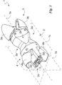
- the reference number 1 indicates, as a whole, the interspinous vertebral distractor according to the invention.
- the distractor 1 is a percutaneous device that can be implanted for interspinous distraction. It is designed to be implanted in an interspinous space so that it is interposed between two adjacent vertebrae and, thus, spaces two spinous processes apart.
- the distractor 1 defines a longitudinal axis 1a that is, suitably, barycentric.
- sagittal plane 1b that is, suitably, barycentric
- frontal plane 1c that is, suitably, barycentric
- the sagittal plane 1b is perpendicular to the frontal plane 1c.
- the intersection between the sagittal plane 1b and the frontal plane 1c defines the axis 1a.
- the distractor 1 comprises a base body 2 that is designed to be placed between two spinous processes by spacing them apart.
- the base body 2 defines, in relation to the longitudinal axis 1a, a first end and a second end.
- the base body 2 has a sagittal section (i.e. defined by the intersection of the sagittal plane 1b with the base body 2) with at least one convexity defining a depression 2a housing a spinous process.
- said sagittal section has two convexities and, therefore, two depressions 2a placed opposite the frontal plane 1c and each one is designed to accommodate a spinous process.
- the depressions 2a may be specular to the frontal plane 1c and, therefore, the sagittal section is symmetrical in relation to the frontal plane 1c.
- the base body 2 may have the minimum sagittal height at the bottom of the at least one depression 2a and, preferably, the maximum sagittal height at the apex of the at least one depression 2a.
- the expression "sagittal height” identifies a length calculated perpendicular to the frontal plane 1c.
- the minimum sagittal height of the base body 2 may be basically less than 100%, in detail less than 85%, and in more detail less than 65% of the maximum sagittal height of the same base body 2.
- the profile of the depression 2a may be elliptical with a suitable eccentricity of less than 1, in detail less than 0.95, and in more detail basically ranging between 0.95 and 0.75, and preferably between 0.9 and 0.8.
- the base body 2 has a frontal section (i.e. defined by the intersection of the frontal plane 1c with the base body 2) tapered with a minimum section close to the first end.
- the frontal section comprises a first proximal sector at the first end of a minimum and suitably constant frontal height; a second proximal sector at the second end of a maximum and suitably constant frontal height; and a central sector joining the first and second sectors and, thus, defining at least one slope 2b between the first and second sectors.
- frontal height identifies a length calculated perpendicular to the sagittal plane 1b.
- the central sector may have an increasing monotonic frontal height.
- the at least one slope 2b is formed at the depressions 2a.
- the radial section of the base body 2 made at the bottom of the depressions 2a has a frontal height and sagittal height basically equal to each other. Said radial section can preferably be circle-shaped.
- the start of the slope 2b i.e. the central sector, is at a shorter axial distance from the first end than the bottom of the depressions 2a.
- radial and axial identify a direction/plane respectively perpendicular and parallel to the longitudinal axis 1a.
- the maximum frontal height and maximum sagittal height may be almost equal.
- the minimum frontal height may be less than the minimum sagittal height.
- the central sector has two slopes 2b on opposite sides to the sagittal plane 1b and suitably almost specular to each other in relation to the sagittal plane 1b. Consequently, the central sector and, thus, the base body 2 may be specular to the sagittal plane 1b.
- the base body 2 may be hollow.
- the distractor 1 comprises a unit 3 for locking the distractor 1 at the spinous processes and, to be precise, between the spinous processes.
- the unit 3 (also called herein anchoring unit or locking unit) is attached to the base body 2 at the first end and can be moved in relation to the body 2 so as to expand radially (in particular perpendicularly to the frontal plane 1c) locking the distractor 1 between the spinous processes.
- the unit 3 is designed to define at least one expanded position wherein it has a maximum radial expansion; and at least one contracted position wherein it has a minimum radial expansion.
- the unit 3 defines the head of the distractor 1 entering between the spinous processes.
- the unit 3 may comprise at least one wing hinged to the base body 2 at the first end defining the rotation axis, which is, suitably, almost parallel to the frontal plane 1c.
- it comprises a first wing 3a hinged to the base body 2 and a second wing 3b hinged to the base body 2 on the opposite side to the first wing 3a in relation to the frontal plane 1c.
- the wings 3a and 3b may have rotation axes that are basically parallel to each other.
- the wings 3a and 3b may rotate simultaneously and in the opposite direction during a change in the position of the unit 3.
- They may have a tapered axial profile with a minimum section distal to the base body 2 so that, in the contracted position, the locking unit 3 is axially tapered and, in particular, ogive.
- the wings 3a and 3b may have a U-shaped radial section with an opening facing the longitudinal axis 1a.
- the distractor 1 may comprise an additional unit 4 for locking the distractor 1 at the spinous processes and, to be precise, between the spinous processes.
- the additional unit 4 is attached to the base body 2 at the second end and can be moved in relation to the body 2 so as to expand radially (in particular perpendicularly to the frontal plane 1c) locking the distractor 1 between the spinous processes.
- the additional unit 4 is designed to define an additional expanded position wherein it has maximum radial expansion; and an additional contracted position wherein it has minimum radial expansion.
- the additional unit 4 may comprise at least one additional wing hinged to the base body 2 at the second end with the rotation axis suitably almost parallel to the frontal plane 1c.
- it comprises a first additional wing 4a hinged to the base body 2 and a second additional wing 4b hinged to the base body 2 on the opposite side to the first additional wing 4a in relation to the frontal plane 1c.
- the additional wings 4a and 4b have rotation axes basically parallel to each other and, in detail, to the wings 3a and 3b.
- the additional wings 4a and 4b rotate simultaneously and in the opposite direction during a change in the position of the additional unit 4.
- the distractor 1 comprises an actuator 5 designed to control the passage of the distractor 1 between an anchoring configuration and an un-anchoring configuration.
- the unit 3 In the anchoring configuration, the unit 3 is in the expanded position locking the distractor 1 in the correct position; and, suitably, the additional unit 4 is in the additional expanded position locking the distractor 1 on the opposite side of the unit 3 in relation to the depression 2a.
- the unit 3 In the un-anchoring configuration, the unit 3 is in the contracted position and not locking the distractor 1 in the correct position; and, suitably, the additional unit 4 is in the additional contracted position.
- the actuator 5 is designed to rotate, specifically exclusively, about the longitudinal axis 1a in relation to the base body 2 by controlling a change in the configuration of the distractor 1.
- the actuator 5, shown in Fig. 5 may comprise a control thread 5a of the unit 3 and, suitably, an additional control thread 5b of the additional unit 4.
- the additional thread 5b may be opposite the thread 5a.
- the unit 3 may comprise, for each wing 3a and/or 3b, at least one thread 5a engagement tooth 3c that, when pushed by the actuator 5, controls the rotation of the wings 3a and/or 3b.
- the additional unit 4 may comprise, for each additional wing 5a and/or 5b, at least one additional thread 5b engagement tooth 4c that, when pushed by the actuator 5, controls the rotation of the additional tooth 4c by controlling the rotation of the additional wings 4a and/or 4b.
- the actuator 5 is externally controlled and the base body 2 comprises an opening 2c for accessing the actuator 5 at the second end.
- the opening 2c is always in view, i.e. accessible from the outside, regardless of the configuration of the distractor 1.
- the additional unit 4 in the contracted position is, therefore, folded over the base body 2 leaving the opening 2c in view.
- the actuator 5 is at least partially housed in the base body 2.
- the distractor 1 can be part of an interspinous vertebral distraction device 10 .
- the distraction device 10 comprises the distractor 1, previously described, and a control 20 for the distractor 1.
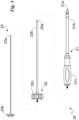
- the control 20, as presented in Figs. 4 and 5 , defines a main extension axis 20a that is preferably barycentric.
- the control 20 may comprise a first tool 21 for controlling the rotation of the distractor 1.
- the first tool 21 is designed to define a first rotational constraint with, suitably exclusively, the base body 2 i.e. a constraint that prevents their mutual rotation about the axes 1a and/or 20a.
- first means 21a designed to be engaged with the body 2, suitably at the opening 2c, defining said first rotational constraint.
- the first means 21a may comprise at least one tip and the base body 2 may comprise at least one seat 2d for inserting said tip.
- they comprise two tips located on opposite sides of the axis 1a and the base body 2 comprises a seat 2d for each tip.
- the first tool 21 comprises a hollow channel 21b and, thus, defines a channel designed to be placed in communication with the opening 2c when the first tool 21 is attached to the base body 2.
- the channel 21a is parallel to the main extension axis 20a.
- the first means 21b protrude from the channel 21b along the main extension axis 20a.
- the first tool 21 may comprise a grip 21c connected to the channel 21b on the opposite side to the means 21a.
- the control 20 may comprise a second tool 22 for controlling the change in configuration of the distractor 1.
- the second tool 22 is designed to define a second rotational constraint with, suitably exclusively, the actuator 5 i.e. a constraint that prevents their mutual rotation about the axes 1a and/or 20a.
- the second constraint is basically an interlocking mechanism.
- the actuator 5 may comprise a polygonal (e.g. hexagonal) end that is in view of the opening 2c and the second means 22a may define a counter-shaped engagement seat at said end.
- the second tool 22 may rotate in relation to the base body 2 and the first tool 21 about the extension axis 20a.
- the second tool 22 may comprise an additional hollow channel 22b and define an additional channel designed to be placed in communication with the opening 2c when the second tool 22 is attached to the actuator 5.
- the additional channel 22a is parallel to the main extension axis 20a.
- the second tool 22 may comprise a head 22c for controlling the second tool 22.
- the head 22c is designed to be placed outside the first tool 21 when the second tool 22 is in the channel 21b.
- the control 20 may comprise a third tool 23 axially constraining at least one of the tools 21 and 22 to the distractor 1.
- the third tool 23 is designed to be engaged with the actuator 5 by defining said axial constraint and, thus, preventing axial motion of the first tool 21 and/or of the second tool 22 in relation to the distractor 1.
- It may comprise third means 23a defining said axial constraint.
- the third tool 23 may comprise a gripping element 23b for controlling the third tool 23.
- the gripping element 23b is designed to be placed outside the first tool 21 and the second tool 22 when the third tool 23 is in the additional channel 22b.
- the third means 23a may define a threaded coupling with the actuator 5.
- the third tool 23 can be at least partially arranged in the additional channel.
- the procedure 100 comprises the distractor 1 and, in particular, the distraction device 10.
- the procedure 100 may comprise a preparation step 110 in which the control 20 is attached to the distractor 1.
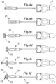
- the preparation step 110 may comprise a first constraint sub-step 111 ( Figs. 6a-6b ) wherein the first tool 21 is engaged to the base body 2 defining said first rotational constraint.
- the first constraint is implemented thanks to the first means 21a by inserting the at least one tip in the at least one seat 2b.
- the preparation step 110 may comprise a second constraint sub-step 112 ( Figs. 6c-6d ) wherein the second tool 22 is engaged with the actuator 5 defining said second rotational constraint.
- the first constraint is implemented by coupling the second means 22a to the actuator 5 by interference.
- the second tool 22 is inserted into the channel 21b.
- the preparation step 110 may comprise a third constraint sub-step 113 ( Figs. 6d-6e ) wherein the third tool 23 is designed to be engaged to the actuator 5 defining said axial constraint.
- the distractor 1 is in the un-anchoring configuration.
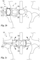
- the procedure 100 may comprise a positioning step 120 ( Figs. 2a-2b ) wherein the distractor 1, suitably controlled by the control 20 and, in particular, by the first tool 21, is brought near the spinous processes.
- the distractor 1 is placed with the frontal plane 1c basically perpendicular to the patient's frontal plane and then moved along the longitudinal axis 1a bringing the locking unit 3 basically to the two spinous processes.
- the distractor 1 then moves axially forward so that the unit 3, in the contracted position, penetrates between the spinous processes and, thanks to its tapered profile, is arranged between them.
- the step 120 ends when the at least one slope 2b is proximal to the spinous processes.
- the procedure 100 may comprise an insertion step 130 ( Figs. 2b-2c ) wherein the base body 2 and, in detail, the entire distractor 1 rotate about the longitudinal axis 1a arranging the frontal plane 1c basically parallel to the patient's frontal plane and, thus, the two spinous processes in the depressions 2a.
- the first tool 21 rotates the distractor 1 and, to be precise, axially moves the distractor 1 and, preferably simultaneously, rotates it about the longitudinal axis 1a.
- the axial translation causes the spinous processes to slide along the slopes 2b so that they gradually adapt to the profile of the sagittal section and, thus, to the at least one depression 2a.
- the rotation enables the depressions 2a to appear and, thus, to house the spinous processes inside, suitably after they have travelled at least part of the slopes 2b.
- the distractor 1 is rotated by an angle basically ranging between 60° and 120°, in detail between 75° and 105°, and preferably around 90°.
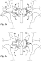
- the procedure 100 may comprise an expansion step 140 ( Figs. 2c-2d ) wherein the distractor 1 switches from the anchoring configuration to the un-anchoring configuration.
- the actuator 5 controlled by the second tool 22, causes the unit 3 to pass into the expanded position so as to constrain the distractor 1 between the spinous processes.
- the actuator 5 suitably controls the passage of the additional unit 4 into the additional expanded position so as to constrain the distractor 1 between the spinous processes on the opposite side to the unit 3 in relation to the depressions 2a.
- the variation in the configuration of the distractor 1 is controlled by rotating the second tool 22 in relation to the first tool 21 that, suitably, remains substantially still.
- the procedure 100 may comprise a removal step 150 ( Fig. 2e ) for moving the control 20 away from the distractor 1.
- step 150 the third tool 23 is disengaged from the actuator 5; then the second tool 23 and then the first tool 21 are moved away from the distractor 1.
- the distractor 1 according to the invention the vertebral distraction device 10 and, thus, the interspinous vertebral distraction procedure 100 (not claimed) achieve important advantages.
- a significant advantage is that the distractor 1 (and, thus, the vertebral distraction device 10 and procedure 100) have low costs.
Landscapes
- Health & Medical Sciences (AREA)
- Orthopedic Medicine & Surgery (AREA)
- Life Sciences & Earth Sciences (AREA)
- Neurology (AREA)
- Surgery (AREA)
- Heart & Thoracic Surgery (AREA)
- Engineering & Computer Science (AREA)
- Biomedical Technology (AREA)
- Nuclear Medicine, Radiotherapy & Molecular Imaging (AREA)
- Medical Informatics (AREA)
- Molecular Biology (AREA)
- Animal Behavior & Ethology (AREA)
- General Health & Medical Sciences (AREA)
- Public Health (AREA)
- Veterinary Medicine (AREA)
- Prostheses (AREA)
Priority Applications (1)
| Application Number | Priority Date | Filing Date | Title |
|---|---|---|---|
| EP23201042.1A EP4306066B1 (en) | 2020-04-08 | 2020-04-08 | Interspinous vertebral distractor |
Applications Claiming Priority (1)
| Application Number | Priority Date | Filing Date | Title |
|---|---|---|---|
| PCT/IB2020/053350 WO2021205209A1 (en) | 2020-04-08 | 2020-04-08 | Interspinous vertebral distractor |
Related Child Applications (2)
| Application Number | Title | Priority Date | Filing Date |
|---|---|---|---|
| EP23201042.1A Division-Into EP4306066B1 (en) | 2020-04-08 | 2020-04-08 | Interspinous vertebral distractor |
| EP23201042.1A Division EP4306066B1 (en) | 2020-04-08 | 2020-04-08 | Interspinous vertebral distractor |
Publications (2)
| Publication Number | Publication Date |
|---|---|
| EP4132392A1 EP4132392A1 (en) | 2023-02-15 |
| EP4132392B1 true EP4132392B1 (en) | 2024-08-28 |
Family
ID=70779802
Family Applications (2)
| Application Number | Title | Priority Date | Filing Date |
|---|---|---|---|
| EP20727366.5A Active EP4132392B1 (en) | 2020-04-08 | 2020-04-08 | Interspinous vertebral distractor |
| EP23201042.1A Active EP4306066B1 (en) | 2020-04-08 | 2020-04-08 | Interspinous vertebral distractor |
Family Applications After (1)
| Application Number | Title | Priority Date | Filing Date |
|---|---|---|---|
| EP23201042.1A Active EP4306066B1 (en) | 2020-04-08 | 2020-04-08 | Interspinous vertebral distractor |
Country Status (6)
| Country | Link |
|---|---|
| EP (2) | EP4132392B1 (pl) |
| JP (1) | JP7537059B2 (pl) |
| CN (1) | CN115443107B (pl) |
| ES (1) | ES2997609T3 (pl) |
| PL (1) | PL4132392T3 (pl) |
| WO (1) | WO2021205209A1 (pl) |
Families Citing this family (1)
| Publication number | Priority date | Publication date | Assignee | Title |
|---|---|---|---|---|
| US12396762B2 (en) | 2020-04-08 | 2025-08-26 | Diametros Medical S.R.L. | Interspinous vertebral distractor |
Family Cites Families (13)
| Publication number | Priority date | Publication date | Assignee | Title |
|---|---|---|---|---|
| US7931674B2 (en) | 2005-03-21 | 2011-04-26 | Kyphon Sarl | Interspinous process implant having deployable wing and method of implantation |
| US8147548B2 (en) | 2005-03-21 | 2012-04-03 | Kyphon Sarl | Interspinous process implant having a thread-shaped wing and method of implantation |
| US8403959B2 (en) * | 2004-12-16 | 2013-03-26 | Med-Titan Spine Gmbh | Implant for the treatment of lumbar spinal canal stenosis |
| US8096994B2 (en) * | 2005-02-17 | 2012-01-17 | Kyphon Sarl | Percutaneous spinal implants and methods |
| US7655043B2 (en) * | 2005-04-29 | 2010-02-02 | Warsaw Orthopedic, Inc. | Expandable spinal implant and associated instrumentation |
| EP2172160A1 (en) * | 2006-06-16 | 2010-04-07 | Kyphon SÀRL | Percutaneous spinal implants and methods |
| US20080108990A1 (en) * | 2006-11-02 | 2008-05-08 | St. Francis Medical Technologies, Inc. | Interspinous process implant having a fixed wing and a deployable wing and method of implantation |
| ITPI20080010A1 (it) | 2008-02-07 | 2009-08-08 | Giuseppe Calvosa | Distrattore vertebrale interspinoso per inserimento percutaneo |
| US8945184B2 (en) * | 2009-03-13 | 2015-02-03 | Spinal Simplicity Llc. | Interspinous process implant and fusion cage spacer |
| WO2012069877A1 (en) * | 2010-11-23 | 2012-05-31 | Giuseppe Calvosa | Intervertebral distractor |
| US9668876B2 (en) | 2013-12-05 | 2017-06-06 | Spinal Elements, Inc. | Expandable interbody device |
| FR3020756B1 (fr) * | 2014-05-06 | 2022-03-11 | Ldr Medical | Implant vertebral, dispositif de fixation vertebrale d'implant et instrumentation d'implantation |
| EP3226774B1 (en) * | 2014-12-04 | 2018-06-13 | Giuseppe Calvosa | Intervertebral distractor |
-
2020
- 2020-04-08 EP EP20727366.5A patent/EP4132392B1/en active Active
- 2020-04-08 WO PCT/IB2020/053350 patent/WO2021205209A1/en not_active Ceased
- 2020-04-08 CN CN202080099520.6A patent/CN115443107B/zh active Active
- 2020-04-08 JP JP2022560352A patent/JP7537059B2/ja active Active
- 2020-04-08 EP EP23201042.1A patent/EP4306066B1/en active Active
- 2020-04-08 ES ES20727366T patent/ES2997609T3/es active Active
- 2020-04-08 PL PL20727366.5T patent/PL4132392T3/pl unknown
Also Published As
| Publication number | Publication date |
|---|---|
| CN115443107B (zh) | 2025-03-25 |
| WO2021205209A1 (en) | 2021-10-14 |
| CN115443107A (zh) | 2022-12-06 |
| EP4306066A2 (en) | 2024-01-17 |
| ES2997609T3 (en) | 2025-02-17 |
| PL4132392T3 (pl) | 2025-01-20 |
| CA3179336A1 (en) | 2021-10-14 |
| JP2023526167A (ja) | 2023-06-21 |
| EP4306066C0 (en) | 2025-04-09 |
| EP4306066A3 (en) | 2024-04-17 |
| EP4132392A1 (en) | 2023-02-15 |
| JP7537059B2 (ja) | 2024-08-21 |
| BR112022020167A2 (pt) | 2022-11-22 |
| EP4306066B1 (en) | 2025-04-09 |
Similar Documents
| Publication | Publication Date | Title |
|---|---|---|
| US12569282B2 (en) | Tissue retraction and vertebral displacement devices, systems, and methods for posterior spinal fusion | |
| AU2022201525B2 (en) | Surgical staple implant kit | |
| US11969162B2 (en) | Systems and methods for performing spine surgery | |
| JP6021638B2 (ja) | 脊椎固定部材を挿入するためのデバイスおよび方法 | |
| AU761818C (en) | Methods and instrumentation for vertebral interbody fusion | |
| EP1488747B1 (en) | Instrumentation for vertebral interbody fusion | |
| US20160120532A1 (en) | Surgical retractor system and method | |
| US20200030010A1 (en) | Devices and methods for inserting a vertebral fixation member | |
| US12256917B2 (en) | Anterior to psoas instrumentation | |
| US12201335B2 (en) | All in one plate holder and spring loaded awl | |
| US12396762B2 (en) | Interspinous vertebral distractor | |
| EP4306066B1 (en) | Interspinous vertebral distractor | |
| WO2021205210A2 (en) | Interspinous vertebral distraction device | |
| WO2021205211A1 (en) | Interspinous vertebral distraction method | |
| CA3179336C (en) | Interspinous vertebral distractor | |
| US20250345102A1 (en) | Interspinous vertebral distractor | |
| AU2022241605A1 (en) | Interspinous vertebral distractor | |
| RU2809569C1 (ru) | Межостистый позвоночный дистрактор | |
| AU2005201167A1 (en) | Methods and instrumentation for vertebral interbody fusion |
Legal Events
| Date | Code | Title | Description |
|---|---|---|---|
| STAA | Information on the status of an ep patent application or granted ep patent |
Free format text: STATUS: UNKNOWN |
|
| STAA | Information on the status of an ep patent application or granted ep patent |
Free format text: STATUS: THE INTERNATIONAL PUBLICATION HAS BEEN MADE |
|
| PUAI | Public reference made under article 153(3) epc to a published international application that has entered the european phase |
Free format text: ORIGINAL CODE: 0009012 |
|
| STAA | Information on the status of an ep patent application or granted ep patent |
Free format text: STATUS: REQUEST FOR EXAMINATION WAS MADE |
|
| 17P | Request for examination filed |
Effective date: 20221005 |
|
| AK | Designated contracting states |
Kind code of ref document: A1 Designated state(s): AL AT BE BG CH CY CZ DE DK EE ES FI FR GB GR HR HU IE IS IT LI LT LU LV MC MK MT NL NO PL PT RO RS SE SI SK SM TR |
|
| DAV | Request for validation of the european patent (deleted) | ||
| DAX | Request for extension of the european patent (deleted) | ||
| GRAP | Despatch of communication of intention to grant a patent |
Free format text: ORIGINAL CODE: EPIDOSNIGR1 |
|
| STAA | Information on the status of an ep patent application or granted ep patent |
Free format text: STATUS: GRANT OF PATENT IS INTENDED |
|
| INTG | Intention to grant announced |
Effective date: 20240417 |
|
| GRAS | Grant fee paid |
Free format text: ORIGINAL CODE: EPIDOSNIGR3 |
|
| GRAA | (expected) grant |
Free format text: ORIGINAL CODE: 0009210 |
|
| STAA | Information on the status of an ep patent application or granted ep patent |
Free format text: STATUS: THE PATENT HAS BEEN GRANTED |
|
| AK | Designated contracting states |
Kind code of ref document: B1 Designated state(s): AL AT BE BG CH CY CZ DE DK EE ES FI FR GB GR HR HU IE IS IT LI LT LU LV MC MK MT NL NO PL PT RO RS SE SI SK SM TR |
|
| REG | Reference to a national code |
Ref country code: CH Ref legal event code: EP |
|
| REG | Reference to a national code |
Ref country code: DE Ref legal event code: R096 Ref document number: 602020036635 Country of ref document: DE |
|
| REG | Reference to a national code |
Ref country code: IE Ref legal event code: FG4D |
|
| REG | Reference to a national code |
Ref country code: NL Ref legal event code: FP |
|
| REG | Reference to a national code |
Ref country code: SE Ref legal event code: TRGR |
|
| REG | Reference to a national code |
Ref country code: LT Ref legal event code: MG9D |
|
| PG25 | Lapsed in a contracting state [announced via postgrant information from national office to epo] |
Ref country code: GR Free format text: LAPSE BECAUSE OF FAILURE TO SUBMIT A TRANSLATION OF THE DESCRIPTION OR TO PAY THE FEE WITHIN THE PRESCRIBED TIME-LIMIT Effective date: 20241129 Ref country code: FI Free format text: LAPSE BECAUSE OF FAILURE TO SUBMIT A TRANSLATION OF THE DESCRIPTION OR TO PAY THE FEE WITHIN THE PRESCRIBED TIME-LIMIT Effective date: 20240828 Ref country code: PT Free format text: LAPSE BECAUSE OF FAILURE TO SUBMIT A TRANSLATION OF THE DESCRIPTION OR TO PAY THE FEE WITHIN THE PRESCRIBED TIME-LIMIT Effective date: 20241230 |
|
| PG25 | Lapsed in a contracting state [announced via postgrant information from national office to epo] |
Ref country code: BG Free format text: LAPSE BECAUSE OF FAILURE TO SUBMIT A TRANSLATION OF THE DESCRIPTION OR TO PAY THE FEE WITHIN THE PRESCRIBED TIME-LIMIT Effective date: 20240828 |
|
| PG25 | Lapsed in a contracting state [announced via postgrant information from national office to epo] |
Ref country code: LV Free format text: LAPSE BECAUSE OF FAILURE TO SUBMIT A TRANSLATION OF THE DESCRIPTION OR TO PAY THE FEE WITHIN THE PRESCRIBED TIME-LIMIT Effective date: 20240828 |
|
| PG25 | Lapsed in a contracting state [announced via postgrant information from national office to epo] |
Ref country code: IS Free format text: LAPSE BECAUSE OF FAILURE TO SUBMIT A TRANSLATION OF THE DESCRIPTION OR TO PAY THE FEE WITHIN THE PRESCRIBED TIME-LIMIT Effective date: 20241228 |
|
| PG25 | Lapsed in a contracting state [announced via postgrant information from national office to epo] |
Ref country code: HR Free format text: LAPSE BECAUSE OF FAILURE TO SUBMIT A TRANSLATION OF THE DESCRIPTION OR TO PAY THE FEE WITHIN THE PRESCRIBED TIME-LIMIT Effective date: 20240828 |
|
| PG25 | Lapsed in a contracting state [announced via postgrant information from national office to epo] |
Ref country code: RS Free format text: LAPSE BECAUSE OF FAILURE TO SUBMIT A TRANSLATION OF THE DESCRIPTION OR TO PAY THE FEE WITHIN THE PRESCRIBED TIME-LIMIT Effective date: 20241128 |
|
| PG25 | Lapsed in a contracting state [announced via postgrant information from national office to epo] |
Ref country code: RS Free format text: LAPSE BECAUSE OF FAILURE TO SUBMIT A TRANSLATION OF THE DESCRIPTION OR TO PAY THE FEE WITHIN THE PRESCRIBED TIME-LIMIT Effective date: 20241128 Ref country code: PT Free format text: LAPSE BECAUSE OF FAILURE TO SUBMIT A TRANSLATION OF THE DESCRIPTION OR TO PAY THE FEE WITHIN THE PRESCRIBED TIME-LIMIT Effective date: 20241230 Ref country code: LV Free format text: LAPSE BECAUSE OF FAILURE TO SUBMIT A TRANSLATION OF THE DESCRIPTION OR TO PAY THE FEE WITHIN THE PRESCRIBED TIME-LIMIT Effective date: 20240828 Ref country code: IS Free format text: LAPSE BECAUSE OF FAILURE TO SUBMIT A TRANSLATION OF THE DESCRIPTION OR TO PAY THE FEE WITHIN THE PRESCRIBED TIME-LIMIT Effective date: 20241228 Ref country code: HR Free format text: LAPSE BECAUSE OF FAILURE TO SUBMIT A TRANSLATION OF THE DESCRIPTION OR TO PAY THE FEE WITHIN THE PRESCRIBED TIME-LIMIT Effective date: 20240828 Ref country code: GR Free format text: LAPSE BECAUSE OF FAILURE TO SUBMIT A TRANSLATION OF THE DESCRIPTION OR TO PAY THE FEE WITHIN THE PRESCRIBED TIME-LIMIT Effective date: 20241129 Ref country code: FI Free format text: LAPSE BECAUSE OF FAILURE TO SUBMIT A TRANSLATION OF THE DESCRIPTION OR TO PAY THE FEE WITHIN THE PRESCRIBED TIME-LIMIT Effective date: 20240828 Ref country code: BG Free format text: LAPSE BECAUSE OF FAILURE TO SUBMIT A TRANSLATION OF THE DESCRIPTION OR TO PAY THE FEE WITHIN THE PRESCRIBED TIME-LIMIT Effective date: 20240828 |
|
| REG | Reference to a national code |
Ref country code: ES Ref legal event code: FG2A Ref document number: 2997609 Country of ref document: ES Kind code of ref document: T3 Effective date: 20250217 |
|
| PG25 | Lapsed in a contracting state [announced via postgrant information from national office to epo] |
Ref country code: SM Free format text: LAPSE BECAUSE OF FAILURE TO SUBMIT A TRANSLATION OF THE DESCRIPTION OR TO PAY THE FEE WITHIN THE PRESCRIBED TIME-LIMIT Effective date: 20240828 Ref country code: DK Free format text: LAPSE BECAUSE OF FAILURE TO SUBMIT A TRANSLATION OF THE DESCRIPTION OR TO PAY THE FEE WITHIN THE PRESCRIBED TIME-LIMIT Effective date: 20240828 Ref country code: RO Free format text: LAPSE BECAUSE OF FAILURE TO SUBMIT A TRANSLATION OF THE DESCRIPTION OR TO PAY THE FEE WITHIN THE PRESCRIBED TIME-LIMIT Effective date: 20240828 |
|
| PG25 | Lapsed in a contracting state [announced via postgrant information from national office to epo] |
Ref country code: EE Free format text: LAPSE BECAUSE OF FAILURE TO SUBMIT A TRANSLATION OF THE DESCRIPTION OR TO PAY THE FEE WITHIN THE PRESCRIBED TIME-LIMIT Effective date: 20240828 |
|
| PG25 | Lapsed in a contracting state [announced via postgrant information from national office to epo] |
Ref country code: CZ Free format text: LAPSE BECAUSE OF FAILURE TO SUBMIT A TRANSLATION OF THE DESCRIPTION OR TO PAY THE FEE WITHIN THE PRESCRIBED TIME-LIMIT Effective date: 20240828 |
|
| PG25 | Lapsed in a contracting state [announced via postgrant information from national office to epo] |
Ref country code: SK Free format text: LAPSE BECAUSE OF FAILURE TO SUBMIT A TRANSLATION OF THE DESCRIPTION OR TO PAY THE FEE WITHIN THE PRESCRIBED TIME-LIMIT Effective date: 20240828 |
|
| REG | Reference to a national code |
Ref country code: DE Ref legal event code: R097 Ref document number: 602020036635 Country of ref document: DE |
|
| PLBE | No opposition filed within time limit |
Free format text: ORIGINAL CODE: 0009261 |
|
| STAA | Information on the status of an ep patent application or granted ep patent |
Free format text: STATUS: NO OPPOSITION FILED WITHIN TIME LIMIT |
|
| 26N | No opposition filed |
Effective date: 20250530 |
|
| REG | Reference to a national code |
Ref country code: AT Ref legal event code: UEP Ref document number: 1717093 Country of ref document: AT Kind code of ref document: T Effective date: 20240828 |
|
| PGFP | Annual fee paid to national office [announced via postgrant information from national office to epo] |
Ref country code: GB Payment date: 20260324 Year of fee payment: 7 |
|
| PGFP | Annual fee paid to national office [announced via postgrant information from national office to epo] |
Ref country code: MC Payment date: 20260327 Year of fee payment: 7 |
|
| PGFP | Annual fee paid to national office [announced via postgrant information from national office to epo] |
Ref country code: IT Payment date: 20260227 Year of fee payment: 7 |
|
| REG | Reference to a national code |
Ref country code: CH Ref legal event code: U11 Free format text: ST27 STATUS EVENT CODE: U-0-0-U10-U11 (AS PROVIDED BY THE NATIONAL OFFICE) Effective date: 20260501 |
|
| PGFP | Annual fee paid to national office [announced via postgrant information from national office to epo] |
Ref country code: LU Payment date: 20260421 Year of fee payment: 7 Ref country code: NL Payment date: 20260422 Year of fee payment: 7 |
|
| PG25 | Lapsed in a contracting state [announced via postgrant information from national office to epo] |
Ref country code: CY Free format text: LAPSE BECAUSE OF FAILURE TO SUBMIT A TRANSLATION OF THE DESCRIPTION OR TO PAY THE FEE WITHIN THE PRESCRIBED TIME-LIMIT Effective date: 20240828 |
|
| PG25 | Lapsed in a contracting state [announced via postgrant information from national office to epo] |
Ref country code: LT Free format text: LAPSE BECAUSE OF FAILURE TO SUBMIT A TRANSLATION OF THE DESCRIPTION OR TO PAY THE FEE WITHIN THE PRESCRIBED TIME-LIMIT Effective date: 20240828 |
|
| PGFP | Annual fee paid to national office [announced via postgrant information from national office to epo] |
Ref country code: ES Payment date: 20260520 Year of fee payment: 7 |
|
| PGFP | Annual fee paid to national office [announced via postgrant information from national office to epo] |
Ref country code: PL Payment date: 20260402 Year of fee payment: 7 |
|
| PGFP | Annual fee paid to national office [announced via postgrant information from national office to epo] |
Ref country code: DE Payment date: 20260420 Year of fee payment: 7 |
|
| PGFP | Annual fee paid to national office [announced via postgrant information from national office to epo] |
Ref country code: NO Payment date: 20260421 Year of fee payment: 7 |
|
| PGFP | Annual fee paid to national office [announced via postgrant information from national office to epo] |
Ref country code: AT Payment date: 20260420 Year of fee payment: 7 Ref country code: SE Payment date: 20260422 Year of fee payment: 7 |
|
| PGFP | Annual fee paid to national office [announced via postgrant information from national office to epo] |
Ref country code: IE Payment date: 20260423 Year of fee payment: 7 Ref country code: BE Payment date: 20260422 Year of fee payment: 7 Ref country code: CH Payment date: 20260501 Year of fee payment: 7 |
|
| PGFP | Annual fee paid to national office [announced via postgrant information from national office to epo] |
Ref country code: TR Payment date: 20260407 Year of fee payment: 7 |
|
| PGFP | Annual fee paid to national office [announced via postgrant information from national office to epo] |
Ref country code: FR Payment date: 20260423 Year of fee payment: 7 |