EP4132432B1 - Dispositif de prothèse actionnable, dispositif de traitement de données électroniques et procédé d'actionnement d'un dispositif de prothèse - Google Patents
Dispositif de prothèse actionnable, dispositif de traitement de données électroniques et procédé d'actionnement d'un dispositif de prothèse Download PDFInfo
- Publication number
- EP4132432B1 EP4132432B1 EP21717379.8A EP21717379A EP4132432B1 EP 4132432 B1 EP4132432 B1 EP 4132432B1 EP 21717379 A EP21717379 A EP 21717379A EP 4132432 B1 EP4132432 B1 EP 4132432B1
- Authority
- EP
- European Patent Office
- Prior art keywords
- prosthesis
- body signal
- sets
- data processing
- electronic data
- Prior art date
- Legal status (The legal status is an assumption and is not a legal conclusion. Google has not performed a legal analysis and makes no representation as to the accuracy of the status listed.)
- Active
Links
Images


Classifications
-
- A—HUMAN NECESSITIES
- A61—MEDICAL OR VETERINARY SCIENCE; HYGIENE
- A61F—FILTERS IMPLANTABLE INTO BLOOD VESSELS; PROSTHESES; DEVICES PROVIDING PATENCY TO, OR PREVENTING COLLAPSING OF, TUBULAR STRUCTURES OF THE BODY, e.g. STENTS; ORTHOPAEDIC, NURSING OR CONTRACEPTIVE DEVICES; FOMENTATION; TREATMENT OR PROTECTION OF EYES OR EARS; BANDAGES, DRESSINGS OR ABSORBENT PADS; FIRST-AID KITS
- A61F2/00—Filters implantable into blood vessels; Prostheses, i.e. artificial substitutes or replacements for parts of the body; Appliances for connecting them with the body; Devices providing patency to, or preventing collapsing of, tubular structures of the body, e.g. stents
- A61F2/50—Prostheses not implantable in the body
- A61F2/68—Operating or control means
- A61F2/70—Operating or control means electrical
- A61F2/72—Bioelectric control, e.g. myoelectric
-
- A—HUMAN NECESSITIES
- A61—MEDICAL OR VETERINARY SCIENCE; HYGIENE
- A61F—FILTERS IMPLANTABLE INTO BLOOD VESSELS; PROSTHESES; DEVICES PROVIDING PATENCY TO, OR PREVENTING COLLAPSING OF, TUBULAR STRUCTURES OF THE BODY, e.g. STENTS; ORTHOPAEDIC, NURSING OR CONTRACEPTIVE DEVICES; FOMENTATION; TREATMENT OR PROTECTION OF EYES OR EARS; BANDAGES, DRESSINGS OR ABSORBENT PADS; FIRST-AID KITS
- A61F2/00—Filters implantable into blood vessels; Prostheses, i.e. artificial substitutes or replacements for parts of the body; Appliances for connecting them with the body; Devices providing patency to, or preventing collapsing of, tubular structures of the body, e.g. stents
- A61F2/50—Prostheses not implantable in the body
- A61F2/54—Artificial arms or hands or parts thereof
- A61F2/58—Elbows; Wrists ; Other joints; Hands
- A61F2/583—Hands; Wrist joints
-
- A—HUMAN NECESSITIES
- A61—MEDICAL OR VETERINARY SCIENCE; HYGIENE
- A61F—FILTERS IMPLANTABLE INTO BLOOD VESSELS; PROSTHESES; DEVICES PROVIDING PATENCY TO, OR PREVENTING COLLAPSING OF, TUBULAR STRUCTURES OF THE BODY, e.g. STENTS; ORTHOPAEDIC, NURSING OR CONTRACEPTIVE DEVICES; FOMENTATION; TREATMENT OR PROTECTION OF EYES OR EARS; BANDAGES, DRESSINGS OR ABSORBENT PADS; FIRST-AID KITS
- A61F2/00—Filters implantable into blood vessels; Prostheses, i.e. artificial substitutes or replacements for parts of the body; Appliances for connecting them with the body; Devices providing patency to, or preventing collapsing of, tubular structures of the body, e.g. stents
- A61F2/50—Prostheses not implantable in the body
- A61F2/68—Operating or control means
- A61F2/70—Operating or control means electrical
- A61F2002/704—Operating or control means electrical computer-controlled, e.g. robotic control
Definitions
- the invention relates to an actuatable prosthesis device, comprising at least one drive, an electronic data processing device and at least one sensor arrangement for arranging on a body part of a prosthesis wearer, wherein the at least one sensor arrangement is configured to detect body signal patterns and the electronic data processing device is configured to control the at least one drive in dependence on a detected body signal pattern such that the prosthesis device executes a prosthesis movement associated with the body signal pattern.
- the invention also relates to an electronic data processing device for such a prosthetic device.
- the invention relates to a method for actuating such a prosthetic device.
- Actuable prosthetic devices include, for example, prostheses of the upper or lower extremities. Prosthetic devices also include prosthetic parts, such as a prosthetic hand or a prosthetic foot. Modern prosthetic devices are usually controlled by an electronic data processing device. For this purpose, the prosthetic device is assigned at least one drive, which can be controlled via the electronic data processing device. In order to be able to execute the most targeted movement possible and to trigger this movement as intuitively and easily as possible by a prosthetic wearer, such an actuable prosthetic device usually has at least one sensor arrangement. This is often arranged on a part of the prosthesis wearer's body to which the prosthetic device is assigned.
- voluntary body signals from the prosthesis wearer can then be detected and transmitted to the electronic data processing device.
- Individual prosthesis movements are then assigned to the body signals, so that the electronic data processing device can control the at least one drive in such a way that the prosthesis device executes the prosthesis movement associated with the body signal.
- body signals include, for example, the contraction of specific individual muscles or muscle groups at a specific intensity and/or frequency, or even co-contractions.
- body signal patterns are complex signal patterns, for example, sequences of muscle contractions of the amputation stump. These can be specifically trained by a prosthesis wearer and, for example, be based on a movement pattern that the prosthesis wearer used to move the limb fitted with the prosthesis when the limb was intact. Particularly in patients whose amputation occurred recently, there is a good memory of the necessary muscle contractions. For example, radial amputees can perform a contraction of the forearm muscles that, when the limb was intact, was associated with a grasping movement of the hand. These body signal patterns are then preferably detected by means of a sensor arrangement, stored in the electronic data processing device and/or a storage medium assigned thereto, and assigned to a specific prosthesis movement, in this example in particular such a grasping movement.
- a command is transmitted to the at least one drive via a control stored in the electronic data processing device to carry out a specific displacement or pivoting of a prosthetic component over a specific path in a specific time.
- the US 2014/100667 A1 relates to a method for controlling at least one powered joint in a prosthesis.
- myoelectric control signals are received from the user during a non-weight-bearing mode for a powered joint.
- a speed reference for a powered joint is generated based on the myoelectric control signals.
- a signal for actuating a powered joint is generated.
- the DE 10 2009 056 466 A1 concerns a method for the adaptive control and regulation of a prosthesis with voluntary control for near-natural movement of a prosthesis.
- the user's muscle activity is measured using an EMG array.
- a voluntary signal is then determined using a classification process that takes into account both the recorded muscle activity and the current movement state. This voluntary signal is used to regulate and control the actuators of a prosthesis.
- the DE 102017 119 490 B3 relates to a prosthetic system with at least two sensors and a control device coupled to the sensors.
- Actuators are activated or deactivated via the control unit to move at least one movably mounted prosthetic component.
- a standard program is stored in the control unit that assigns an actuator action to each sensor, regardless of the duration and/or intensity of the sensor signal. This allows the functionality of the prosthetic system to be checked.
- the US 2016/0051382 A1 relates to a method for operating a gripping device using a plurality of parallel, bidirectional state flow maps, each defining a sequence of positions for a plurality of joints in the gripping device.
- the method comprises receiving at least one control signal, determining a current position of the gripping device within one of the plurality of state flow maps currently selected for the gripping device, and selectively actuating the plurality of joints to traverse the sequence of positions, wherein a direction for traversing the sequence of positions is determined based on the at least one control signal.
- the US 2016/0101596 A1 relates to a method for setting up a control system for an orthopedic device that is attached to a patient's body part and connected to sensors that record biometric data from the patient, and for controlling the orthopedic device.
- a representation of an actuation of a limb is output in order to prompt a patient to perform this actuation.
- Biometric signals generated by the patient as a voluntary response upon request are recorded, and the generated signals are assigned to the actuation performed. The signal assignment is then saved.
- the object of the present invention is to propose a prosthetic device that can be actuated as easily as possible and with which a larger number of prosthetic movements are possible.
- the actuatable prosthesis device with at least one drive, an electronic data processing device and at least one sensor arrangement for arrangement on a body part of a prosthesis wearer, wherein the at least one sensor arrangement is set up to detect body signal patterns and the electronic data processing device is set up to control the at least one drive as a function of a detected body signal pattern such that the prosthesis device executes a prosthesis movement associated with the body signal pattern, provides that at least two sets of body signal patterns and prosthesis movements associated with them are stored in the electronic data processing device, and at least one trigger signal is assigned to the sets, which switches between the sets, wherein in several sets, preferably in each set, the same prosthesis movements are assigned to one or more body signal patterns.
- the number of prosthetic movements that can be carried out by the actuatable prosthetic device can be increased in a simple manner.
- the electronic data processing device contains exactly two sets and exactly one trigger signal.
- the prosthesis wearer performs a movement, in particular a Muscle contraction pattern, which is recorded by the sensor arrangement and recognized by the electronic data processing device as a specific body signal pattern.
- the electronic data processing device then first checks which of the two sets is selected and controls the drive according to the prosthesis movement assigned to the body signal pattern in the selected set. For example, to switch from the first set to the second set, the trigger signal must be triggered once. To switch from the second set back to the first set, the trigger signal is triggered again.
- the prosthesis wearer has selected the desired set using the trigger signal, they perform the movement or muscle contraction pattern that corresponds to the body signal pattern for the desired prosthesis movement.
- Such sequential switching offers the advantage that the prosthesis wearer only has to learn and/or remember one trigger signal.
- each set the same prosthetic movements are assigned to one or more body signal patterns.
- prosthetic movements 1 to 4 are assigned to body signal patterns 1 to 4.
- body signal pattern 1 is again assigned to prosthetic movement 1, but body signal patterns 2 to 4 are assigned to prosthetic movements 5 to 7.
- This is particularly advantageous when a prosthetic movement, in this example prosthetic movement 1, is a particularly frequently performed prosthetic movement. This can then be triggered with the same body signal pattern, regardless of which set is currently being used. This avoids unnecessarily frequent switching using the at least one trigger signal and increases user comfort.
- each set is assigned a different trigger signal, which then encodes precisely for that set.
- a first trigger signal can be assigned to a first set, a second trigger signal to a second set, and a third trigger signal to a third set.
- the system switches directly to the corresponding set. This is advantageous, for example, when two sets are present, since the prosthesis wearer does not need to know which set is currently selected to select a specific set. This design is particularly advantageous when more than two sets are present, as it eliminates the need for time-consuming sequential switching.
- the prosthetic device comprises a display device that indicates the currently selected set. This can be, for example, a display or one or more LEDs.
- one of the sets is stored as the standard set.
- the setting to the standard set occurs automatically. For example, this occurs automatically after a predetermined period of time, for example at least 10 seconds, in particular at least 30 seconds. This time period is preferably individually adjustable. In this way, it is not necessary for the prosthesis wearer to memorize the currently selected set or for a display device to be present to show them the currently selected set. If the prosthesis wearer has not allowed the prosthesis device to perform any prosthesis movement for a while, they know that they are always in the first set.
- a display device for the currently selected set is present.
- the standard set is initially only selected when switched on. If a trigger signal is subsequently generated and a switch is made from the standard set to a first or second set, these can also remain in the selected state.
- At least one body signal pattern is contained identically in the sets, wherein different prosthesis movements are assigned to the at least one identically contained body signal pattern in the sets.
- At least one body signal pattern is identically included in the sets ensures that this at least one body signal pattern is assigned twice, i.e., the same body signal pattern encodes more than one prosthetic movement.
- the prosthetic movement to be executed via the specific body signal pattern can be selected accordingly.
- more than one body signal pattern may be identical in the sets.
- two, three, four, five, six, seven, or eight of the body signal patterns contained in the sets may be identical.
- At least three, more preferably at least four sets are stored in the electronic data processing device, so that the number of prosthesis movements is greatly increased without having to increase the demands on the prosthesis wearer, namely to learn additional body signal patterns.
- the at least one trigger signal is a fixed body signal that deviates from the body signal patterns stored in the sets. Therefore, the at least one trigger signal is preferably not an independent Body signal patterns are not a specific body signal, but rather a body signal such as a co-contraction of a specific muscle or muscle group. This is particularly advantageous in order not to assign at least one trigger signal to one of the few available body signal patterns, but rather to keep this free for one or more prosthesis movements.
- the respective trigger signals can belong to the same category, i.e., they can all be different co-contractions.
- the different trigger signals can belong to different categories, for example, co-contractions, contraction patterns, contraction duration and/or contraction intensity.
- each set comprises at least four body signal patterns, in particular at least six body signal patterns.
- the number of body signal patterns per set can be determined, for example, depending on the level of experience of the prosthesis wearer for whom the respective prosthesis device is intended. For inexperienced and untrained prosthesis wearers, it may be advantageous, for example, to provide only exactly two, exactly three, or exactly four body signal patterns per set. For some, particularly more experienced wearers, however, it may be advantageous to have exactly five, exactly six, exactly seven, or exactly eight body signal patterns stored per set. Each set preferably contains no more than twelve, and particularly preferably no more than 10, body signal patterns, since the vast majority of prosthesis users cannot produce these with the necessary precision and distinguishability.
- the at least one sensor arrangement comprises a plurality of electrode pairs for detecting the body signal patterns and in particular a pair of electrodes for detecting the at least one trigger signal.
- the at least one sensor arrangement preferably has a plurality of electrode pairs for detecting the body signal patterns, for example at least two, particularly preferably at least four, in particular exactly four electrode pairs. It is possible for a further electrode pair to be present for detecting the at least one trigger signal. However, it is also possible for one of the electrode pairs for detecting the body signal patterns to simultaneously be the electrode pair for detecting the at least one trigger signal.
- the sensor arrangement or the electrode pair for detecting the at least one trigger signal can also be arranged in particular on a limb or on a body part that is not functionally connected to the prosthesis or prosthetic component.
- the electrodes of the at least one sensor arrangement are preferably arranged uniformly or substantially uniformly spaced from one another around the limb, the limb stump or the amputation stump, for example at a distance of 60° or approximately 60° from one another in the case of six electrodes, at a distance of 45° or approximately 45° from one another in the case of eight electrodes and at a distance of 90° or approximately 90° from one another in the case of four electrodes.
- the number of electrodes or electrode pairs required depends on the complexity of the respective prosthetic device and the movements to be performed.
- complex prosthetic devices, to which this invention particularly relates for example, with a powered prosthetic elbow joint, a prosthetic hand with individually movable prosthetic fingers, and/or a flexible and/or rotatable wrist, more than eight electrode pairs are sometimes necessary.
- the type of supply and the number of electrode pairs also depend on the wearer's ability to generate certain complex body signal patterns.
- the sets can be at least partially modified using an input device.
- a computer can be connected wirelessly or via a cable to the electronic data processing device and modify the sets stored therein.
- an app which can be installed, for example, on a smartphone of the respective prosthesis wearer or an orthopedic technician.
- the sets are variable means, for example, that the number of body signal patterns stored per set is variable and/or the stored prosthetic movements and/or the assignment of a specific prosthetic movement to a specific body signal pattern is variable. Additionally or alternatively, the body signal patterns themselves, in particular which muscles or muscle groups are to be contracted for a specific body signal pattern, or the associated specifications and parameters, can also be set or changed.
- signal quality is understood, among other things, to mean the separability of the signals, in particular the shape or course of the signal or the location where the signal is recorded. Furthermore, the repeatability of the signal is a quality criterion. High signal quality is achieved when the signal always looks the same, i.e. when a patient can always generate the same signal. The sustainability of the signal is also relevant for the signal quality. If the signal can be generated and recorded over a longer period of time, this is better than just a short-lasting signal, which could possibly be perceived as a disturbance and not taken into account.
- the patient is asked to perform muscle activities, for example, to perform the activity that the prosthetic device is intended to perform, such as opening the hand, closing the hand, rotating the wrist, or flexing the hand.
- this activity cannot be performed directly by the patient, since the The limb replaced by the prosthetic device is missing, but the remaining muscles can be partially activated as before the loss of the limb.
- This creates electrical potentials that are recorded by the at least one sensor arrangement and transmitted to the electronic data processing device. Based on, for example, the signal duration, signal intensity, edge slope, or even a signal frequency during muscle contractions, it is possible to determine whether a specific movement or a specific muscle contraction pattern is suitable for use as a body signal pattern.
- the input device in particular the app, to indicate to a prosthesis wearer which sensor arrangement is currently detecting which signal.
- the signal quality of the signal is additionally displayed visually. This allows the prosthesis wearer to execute certain muscle contraction patterns and, via the input device, to display what the at least one sensor arrangement has detected. This makes it possible, in particular, for the prosthesis wearer to train the execution of the body signal patterns or, if necessary, to adapt the body signal patterns to the actual sensor values obtained.
- the invention solves the stated problem by means of an electronic data processing device for such a prosthesis device, wherein at least two sets of body signal patterns and prostheses respectively assigned to them are stored in the electronic data processing device and at least one trigger signal is assigned to the sets, which switches between the sets, wherein the same prosthesis movement is assigned to at least one body signal pattern independently of the set.
- the invention solves the stated problem by a method for actuating a prosthetic device comprising the steps: a) selecting a set to be used from the at least two in the electronic sets stored in the data processing device by exerting the at least one trigger signal, b) detecting a body signal pattern of the prosthesis wearer by means of the at least one sensor arrangement, and c) actuating the prosthesis device by means of the at least one drive as a function of the detected body signal pattern and the selected set, so that the prosthesis device executes the prosthesis movement which is associated with the detected body signal pattern in the selected set, wherein the same prosthesis movement is executed for at least one body signal pattern regardless of the selected set.
- step c) comprises the following steps: conducting a sensor signal coding for the detected body signal pattern from the sensor arrangement to the electronic data processing device, evaluating the sensor signal in the electronic data processing device, determining a prosthetic movement to be carried out as a function of the sensor signal and the selected set and generating a control signal coding for the prosthetic movement to be carried out, conducting the control signal to the at least one drive of the prosthetic device, and operating the at least one drive as a function of the control signal, so that the prosthetic device carries out the prosthetic movement to be carried out.
- the sensor signal or the sensor signals and the control signal are transmitted to the electronic data processing device, for example via a data cable or wirelessly.
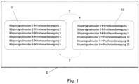
- FIG. 1 An electronic data processing device E is indicated, in which a first set S1 and a second set S2 are stored.
- the sets S1, S2 each have six body signal patterns.
- the body signal patterns in both sets S1, S2 are completely identical, namely body signal patterns 1 to 6.
- Each body signal pattern is assigned a prosthetic movement.
- the body signal patterns 1 to 6 are assigned prosthetic movements 1 to 6.
- the same body signal patterns 1 to 6 are assigned other prosthetic movements, namely prosthetic movements 7 to 12.
- This division makes it possible to trigger twelve different prosthetic movements with only six different body signal patterns.
- only one trigger signal T is present.
- the prosthesis wearer To switch between the sets S1, S2, the prosthesis wearer must execute or generate the trigger signal T. This is, for example, a co-contraction of a specific muscle or muscle group.
- This trigger signal T is then used to switch between sets S1 and S2.
- a first trigger signal T1 is assigned to the first set S1
- a second trigger signal T2 is assigned to the second set S2.
- the first trigger signal T1 differs from the second trigger signal T2. Applying or generating the first trigger signal T1 always switches to the first set S1, and applying or executing the second trigger signal T2 always switches to the second set S2.
- one of the two sets S1 or S2 is assigned a further, time-dependent switching signal.
- the electronic data processing device E automatically switches from set S2 to set S1 after 10 seconds, 20 seconds, or 30 seconds, unless this has been done by the wearer of the prosthetic device by triggering the trigger signal T.
- set S1 then forms the standard set.
- FIG. 2 A schematic flow diagram is shown. The process to be controlled and not in the Figure 2 , but in the Figures 3 and 4
- the prosthetic device 2 shown has a sensor arrangement 6 with eight electrode pairs 8, which can be seen from the eight signals indicated on the left. These signals are the result of a movement and/or a plurality of muscle contractions of a prosthesis wearer. These are transmitted to the electronic data processing device E and evaluated there, i.e., amplified if necessary, filtered, and in particular compared with body signal patterns stored in the electronic data processing device E.
- two sets, S1 and S2 are stored in the electronic data processing device E. In each set, three body signal patterns X, Y and Z are stored. In the first set S1, the body signal patterns X, Y, Z are assigned the prosthesis movements 1 to 3. In the second set S2, the same body signal patterns X, Y, Z are assigned the prosthesis movements 4 to 6, which differ from the prosthesis movements 1 to 3.
- the electronic data processing device E If the electronic data processing device E has detected, for example, that the body signal pattern X is present, the electronic data processing device E then checks which of the two sets S1 or S2 is selected. The selection was previously made, for example, by applying an associated trigger signal T.
- prosthesis movement 1 is executed based on the detected body signal pattern X. If the second set S2 is selected, prosthesis movement 4 is executed based on the detected body signal pattern X.
- FIG. 3 shows a schematic representation of an embodiment of the actuatable prosthetic device 2 of an upper extremity. Along its longitudinal axis, the prosthetic device 2 is partially shown in an exploded view.
- the prosthetic device 2 is designed as a prosthetic forearm and has several drives 4, a sensor arrangement 6 with a plurality of electrode pairs 8, and an electronic data processing device E.
- the Figure 3 The right drive 4 shown serves to rotate a prosthetic hand 10 of the prosthetic device 2 relative to a forearm shaft 12 of the Prosthetic device 2 around the longitudinal axis of the forearm shaft 12.
- the prosthetic hand 10 has a plurality of further drives 4 within the prosthetic hand 10, which serve to actuate the prosthetic fingers 14 of the prosthetic hand 10.
- the sensor arrangement 6 has four electrode pairs 8. These are designed, for example, as individual electrode pairs 8, each of which can be attached to the skin of a prosthesis wearer. According to a further embodiment, the electrode pairs 8 are applied to a prosthesis liner (not shown), for example, glued or integrally connected or formed with the liner. According to a further embodiment, the electrode pairs 8 are arranged on an inner side of the forearm shaft 12.
- the electrode pairs 8 are each connected to the electronic data processing device E via sensor lines 16.
- the signals detected by the electrodes are transmitted to the electronic data processing device E via the sensor lines 16.
- the signals are evaluated in the electronic data processing device E, in particular to determine whether and to which body signal pattern the received signals correspond. Subsequently, a prosthetic movement to be performed is determined based on the detected body signal pattern and the selected set. A control signal encoding this prosthetic movement to be performed is then transmitted to the drives 4 via the drive lines 18.
- the electronic data processing device E is connected wirelessly, for example via radio, to an input device 20. Signals received from the sensor arrangement 6, for example, can be visualized via this input device 20. Furthermore, it is preferably possible to change the sets and/or trigger signals stored in the electronic data processing device E. For example, the type and number of body signal patterns and/or prosthesis movements can be changed.
- the input device 20 is a smartphone, in particular that of the prosthesis wearer. This allows the wearer to display the signals detected by the sensor array 6. Additionally, a target value, for example, a target intensity, of the respective signal is preferably displayed. This allows the wearer to determine whether the quality of their performance is sufficient. If this is not the case, the wearer can either train or adjust the target values to reflect the actual performance.
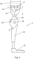
- FIG 4 is a further embodiment of the actuatable prosthetic device 2, presently in the form of a prosthetic leg for a patient with a transfemoral amputation.
- the prosthetic device 2 has a sensor arrangement 6 with several, e.g. six, electrode pairs 8, of which only four are in Figure 4 are visible.
- the prosthetic device 2 comprises a prosthetic foot 22 and a lower leg part 24.
- a prosthetic knee joint 26 is arranged on the lower leg part 24, which has an upper joint part 28.
- a damper 30 or actuator is assigned to the prosthetic knee joint 26.
- a prosthetic shaft is arranged on the upper joint part 28, which, for the sake of clarity, is shown in Figure 4 is not shown. Instead, the underlying limb stump 32 of a prosthesis wearer is indicated.
- the prosthetic knee joint 26 can also be assigned a drive (not shown) that actuates a flexion or extension movement of the prosthetic device 2. Control signals from the electronic data processing device E are supplied to this drive 4 via drive lines 18 (also not shown).
- the sensor arrangement 6 comprises a flexible, particularly elastic, belt 34 on which the electrode pairs 8 are arranged. This belt is arranged around the limb stump 34 so that the electrode pairs 8 rest against it and can detect corresponding signals. Sensor lines 16 run from the electrode pairs 8 to the electronic data processing device E.
Landscapes
- Health & Medical Sciences (AREA)
- Engineering & Computer Science (AREA)
- Biomedical Technology (AREA)
- Public Health (AREA)
- General Health & Medical Sciences (AREA)
- Life Sciences & Earth Sciences (AREA)
- Veterinary Medicine (AREA)
- Vascular Medicine (AREA)
- Transplantation (AREA)
- Animal Behavior & Ethology (AREA)
- Oral & Maxillofacial Surgery (AREA)
- Cardiology (AREA)
- Heart & Thoracic Surgery (AREA)
- Prostheses (AREA)
- Business, Economics & Management (AREA)
- General Business, Economics & Management (AREA)
- Epidemiology (AREA)
- Medical Informatics (AREA)
- Primary Health Care (AREA)
Claims (10)
- Dispositif de prothèse actionnable (2), comprenantau moins un entraînement (4),un dispositif électronique de traitement de données (E), etau moins une unité de détection (6) destinée à être disposée sur une partie du corps d'un porteur de prothèse,dans lequelladite au moins une unité de détection (6) est conçue pour détecter des modèles de signaux corporels (X, Y, Z), et le dispositif électronique de traitement de données (E) est conçu pour commander ledit au moins un entraînement (4) en fonction d'un modèle de signal corporel (X, Y, Z) détecté, de telle sorte que le dispositif de prothèse (2) exécute un mouvement de prothèse associé au modèle de signal corporel (X, Y, Z),au moins deux jeux (S1, S2) de modèles de signaux corporels (X, Y, Z) et de mouvements de prothèse respectivement associés à ceux-ci sont stockés dans le dispositif électronique de traitement de données (E), etau moins un signal de déclenchement (T) est associé auxdits jeux (S1, S2), lequel commute entre les jeux (S1, S2),caractérisé en ce queles mêmes mouvement de prothèse respectifs sont associés à un ou à plusieurs modèles de signaux corporels (X, Y, Z) dans plusieurs jeux (S1, S2), de préférence dans chaque jeu (S1, S2).
- Dispositif de prothèse actionnable (2) selon la revendication 1,
caractérisé en ce qu'au moins un modèle de signal corporel (X, Y, Z) est contenu de manière identique dans les jeux (S1, S2), des mouvements de prothèse respectifs différents étant associés audit au moins un modèle de signal corporel (X, Y, Z) contenu de manière identique dans les jeux (S1, S2). - Dispositif de prothèse actionnable (2) selon l'une des revendications 1 ou 2,
caractérisé en ce que chaque jeu (S1, S2) contient les modèles de signaux corporels identiques (X, Y, Z). - Dispositif de prothèse actionnable (2) selon l'une des revendications précédentes,
caractérisé en ce que ledit au moins un signal de déclenchement (T) est un signal corporel fixé qui diffère des modèles de signaux corporels (X, Y, Z) stockés dans les jeux (S1, S2). - Dispositif de prothèse actionnable (2) selon l'une des revendications précédentes,
caractérisé en ce que chaque jeu (S1, S2) comprend au moins quatre modèles de signaux corporels (X, Y, Z), en particulier au moins six modèles de signaux corporels (X, Y, Z). - Dispositif de prothèse actionnable (2) selon l'une des revendications précédentes,
caractérisé en ce que l'unité de détection (6) comprend plusieurs paires d'électrodes (8) destinées à détecter les modèles de signaux corporels (X, Y, Z) et en particulier une paire d'électrodes (8) destinées à détecter ledit au moins un signal de déclenchement (T). - Dispositif de prothèse actionnable (2) selon l'une des revendications précédentes,
caractérisé en ce que les jeux (S1, S2) peuvent être modifiés au moyen d'un appareil d'entrée (20). - Dispositif électronique de traitement de données (E) pour un dispositif de prothèse actionnable (2) selon l'une des revendications précédentes,
dans lequel au moins deux jeux (S1, S2) de modèles de signaux corporels (X, Y, Z) et de mouvements de prothèse respectivement associés à ceux-ci sont stockés dans le dispositif électronique de traitement de données (E), et au moins un signal de déclenchement (T) est associé aux jeux (S1, S2), lequel commute entre les jeux (S1, S2), et le même mouvement de prothèse est associé à au moins un modèle de signal corporel (X, Y, Z) indépendamment du jeu (S1, S2). - Procédé d'actionnement d'un dispositif de prothèse actionnable (2) selon l'une des revendications 1 à 7,
comprenant les étapes consistant à :a) sélectionner un jeu à appliquer (S1, S2) parmi lesdits au moins deux jeux (S1, S2) stockés dans le dispositif électronique de traitement de données (E), en appliquant ledit au moins un signal de déclenchement (T),b) détecter un modèle de signal corporel (X, Y, Z) du porteur de la prothèse au moyen de ladite au moins une unité de détection (6), etc) actionner le dispositif de prothèse (2) au moyen dudit au moins un entraînement (4) en fonction du modèle de signal corporel (X, Y, Z) détecté et du jeu (S1, S2) sélectionné, de sorte que le dispositif de prothèse (2) exécute le mouvement de prothèse associé au modèle de signal corporel détecté (X, Y, Z) dans le jeu (S1, S2) sélectionné, sachant que le même mouvement de prothèse est exécuté pour au moins un modèle de signal corporel, indépendamment du jeu (S1, S2) sélectionné. - Procédé selon la revendication 9,
caractérisé en ce que l'étape c) comprend les étapes suivantes consistant à :c1) transmettre un signal de détection, encodant le modèle de signal corporel (X, Y, Z) détecté, de l'unité de détection (6) au dispositif électronique de traitement de données (E),c2) évaluer le signal de détection dans le dispositif électronique de traitement de données (E),c3) déterminer un mouvement de prothèse à exécuter en fonction du signal de détection et du jeu (S1, S2) sélectionné, et générer un signal de commande encodant le mouvement de prothèse à exécuter,c3) transmettre le signal de commande audit au moins un entraînement (4) du dispositif de prothèse (2), etc4) faire fonctionner ledit au moins un entraînement (4) en fonction du signal de commande, de sorte que le dispositif de prothèse (2) exécute le mouvement de prothèse à exécuter.
Applications Claiming Priority (2)
| Application Number | Priority Date | Filing Date | Title |
|---|---|---|---|
| DE102020109509.0A DE102020109509A1 (de) | 2020-04-06 | 2020-04-06 | Aktuierbare Protheseneinrichtung, elektronische Datenverarbeitungseinrichtung und Verfahren zum Aktuieren einer Protheseneinrichtung |
| PCT/EP2021/058674 WO2021204690A1 (fr) | 2020-04-06 | 2021-04-01 | Dispositif de prothèse actionnable, dispositif de traitement de données électroniques et procédé d'actionnement d'un dispositif de prothèse |
Publications (2)
| Publication Number | Publication Date |
|---|---|
| EP4132432A1 EP4132432A1 (fr) | 2023-02-15 |
| EP4132432B1 true EP4132432B1 (fr) | 2025-05-28 |
Family
ID=75438757
Family Applications (1)
| Application Number | Title | Priority Date | Filing Date |
|---|---|---|---|
| EP21717379.8A Active EP4132432B1 (fr) | 2020-04-06 | 2021-04-01 | Dispositif de prothèse actionnable, dispositif de traitement de données électroniques et procédé d'actionnement d'un dispositif de prothèse |
Country Status (4)
| Country | Link |
|---|---|
| US (1) | US20230149187A1 (fr) |
| EP (1) | EP4132432B1 (fr) |
| DE (1) | DE102020109509A1 (fr) |
| WO (1) | WO2021204690A1 (fr) |
Family Cites Families (6)
| Publication number | Priority date | Publication date | Assignee | Title |
|---|---|---|---|---|
| DE102009030217A1 (de) * | 2009-06-23 | 2011-01-05 | Otto Bock Healthcare Products Gmbh | Verfahren zum Einrichten einer Steuerung und orthopädietechnische Einrichtung |
| DE102009056466A1 (de) * | 2009-12-01 | 2011-06-09 | Fraunhofer-Gesellschaft zur Förderung der angewandten Forschung e.V. | Adaptives Steuerungs- und Regelungssystem für Prothesen mit willkürlicher Steuerung |
| EP3000391B1 (fr) * | 2010-07-01 | 2019-01-30 | Vanderbilt University | Système de commande volontaire de dispositifs mécaniques articulés sur la base d'électromyographie de surface |
| CA2818256C (fr) | 2010-11-22 | 2019-04-16 | Vanderbilt University | Systeme de commande d'un dispositif de prehension |
| ES1187509Y (es) * | 2017-03-31 | 2017-10-03 | Centro Ortopedico Tecnologico S L U | Prótesis microeléctrica |
| DE102017119490B3 (de) | 2017-08-25 | 2018-11-15 | Otto Bock Healthcare Products Gmbh | Prothesensystem und Verfahren zur Überprüfung der Funktionsfähigkeit eines Prothesensystems |
-
2020
- 2020-04-06 DE DE102020109509.0A patent/DE102020109509A1/de active Pending
-
2021
- 2021-04-01 US US17/917,098 patent/US20230149187A1/en active Pending
- 2021-04-01 EP EP21717379.8A patent/EP4132432B1/fr active Active
- 2021-04-01 WO PCT/EP2021/058674 patent/WO2021204690A1/fr not_active Ceased
Also Published As
| Publication number | Publication date |
|---|---|
| US20230149187A1 (en) | 2023-05-18 |
| DE102020109509A1 (de) | 2021-10-07 |
| WO2021204690A1 (fr) | 2021-10-14 |
| EP4132432A1 (fr) | 2023-02-15 |
Similar Documents
| Publication | Publication Date | Title |
|---|---|---|
| EP2445456B1 (fr) | Procédé d'ajustement d'une commande et dispositif technico-orthopédique | |
| EP3672536B1 (fr) | Systeme de prothese et procedure pour la verification du fonctionnement d'un systeme de prothese | |
| EP3790515B1 (fr) | Procédé de configuration d'un système de prothèse commandé myoélectriquement et système de prothèse | |
| EP0203156B1 (fr) | Main prehensile pour manipulateur | |
| EP2879622B1 (fr) | Commande d'orthèse | |
| WO2016107679A1 (fr) | Dispositifs et procédés haptiques | |
| EP4142657A1 (fr) | Méthode de contrôle d'au moins un actionneur d'un dispositif orthopédique et dispositif orthopédique | |
| EP3773351B1 (fr) | Système d'orthèses ou de prothèses pour la commande ou le réglage d'orthèses ou de prothèses | |
| EP4132432B1 (fr) | Dispositif de prothèse actionnable, dispositif de traitement de données électroniques et procédé d'actionnement d'un dispositif de prothèse | |
| DE102008036714B4 (de) | Verfahren zur Visualisierung mehrkanaliger Signale | |
| DE102007013660A1 (de) | Exoprothese | |
| DE102020116536A1 (de) | Protheseneinrichtung mit einer Prothesenhand und Verfahren zum Betreiben einer Protheseneinrichtung | |
| AT521791B1 (de) | Rückmeldungssystem für eine Prothese, insbesondere für eine Armprothese, und Verfahren zum Erzeugen eines Stimulus für den Träger der Prothese mittels eines solchen Rückmeldungssystems | |
| DE2016295A1 (de) | Taktile Rückmeldeeinrichtung für künstliche menschliche Gliedmaßen, insbesondere Kunsthände | |
| DE102014001390A1 (de) | Verfahren zum Steuern einer Prothese | |
| EP3448321B1 (fr) | Prothèse | |
| EP4138740B1 (fr) | Procédé de transmission de données | |
| EP3870117B1 (fr) | Procédé de configuration d'une commande d'un dispositif technique orthopédique et système de mise en oeuvre du procédé | |
| WO2023138784A1 (fr) | Système et procédé de configuration d'un robot | |
| Harnoncourt et al. | Prosthetic Fitting Concepts after Major Amputation in the Upper Limb–an Overview of Current Possibilities | |
| DE7012439U (de) | Anordnung einer taktilen rueckmeldeeinrichtung an kuenstlichen menschlichen gliedmassen, insbesondere an motorisch angetriebenen hand- und armprothesen. |
Legal Events
| Date | Code | Title | Description |
|---|---|---|---|
| STAA | Information on the status of an ep patent application or granted ep patent |
Free format text: STATUS: UNKNOWN |
|
| STAA | Information on the status of an ep patent application or granted ep patent |
Free format text: STATUS: THE INTERNATIONAL PUBLICATION HAS BEEN MADE |
|
| PUAI | Public reference made under article 153(3) epc to a published international application that has entered the european phase |
Free format text: ORIGINAL CODE: 0009012 |
|
| STAA | Information on the status of an ep patent application or granted ep patent |
Free format text: STATUS: REQUEST FOR EXAMINATION WAS MADE |
|
| 17P | Request for examination filed |
Effective date: 20221025 |
|
| AK | Designated contracting states |
Kind code of ref document: A1 Designated state(s): AL AT BE BG CH CY CZ DE DK EE ES FI FR GB GR HR HU IE IS IT LI LT LU LV MC MK MT NL NO PL PT RO RS SE SI SK SM TR |
|
| DAV | Request for validation of the european patent (deleted) | ||
| DAX | Request for extension of the european patent (deleted) | ||
| GRAP | Despatch of communication of intention to grant a patent |
Free format text: ORIGINAL CODE: EPIDOSNIGR1 |
|
| STAA | Information on the status of an ep patent application or granted ep patent |
Free format text: STATUS: GRANT OF PATENT IS INTENDED |
|
| INTG | Intention to grant announced |
Effective date: 20250213 |
|
| GRAS | Grant fee paid |
Free format text: ORIGINAL CODE: EPIDOSNIGR3 |
|
| GRAA | (expected) grant |
Free format text: ORIGINAL CODE: 0009210 |
|
| STAA | Information on the status of an ep patent application or granted ep patent |
Free format text: STATUS: THE PATENT HAS BEEN GRANTED |
|
| AK | Designated contracting states |
Kind code of ref document: B1 Designated state(s): AL AT BE BG CH CY CZ DE DK EE ES FI FR GB GR HR HU IE IS IT LI LT LU LV MC MK MT NL NO PL PT RO RS SE SI SK SM TR |
|
| REG | Reference to a national code |
Ref country code: GB Ref legal event code: FG4D Free format text: NOT ENGLISH |
|
| REG | Reference to a national code |
Ref country code: CH Ref legal event code: EP |
|
| REG | Reference to a national code |
Ref country code: IE Ref legal event code: FG4D Free format text: LANGUAGE OF EP DOCUMENT: GERMAN Ref country code: DE Ref legal event code: R096 Ref document number: 502021007588 Country of ref document: DE |
|
| REG | Reference to a national code |
Ref country code: SE Ref legal event code: TRGR |
|
| REG | Reference to a national code |
Ref country code: NL Ref legal event code: MP Effective date: 20250528 |
|
| PG25 | Lapsed in a contracting state [announced via postgrant information from national office to epo] |
Ref country code: ES Free format text: LAPSE BECAUSE OF FAILURE TO SUBMIT A TRANSLATION OF THE DESCRIPTION OR TO PAY THE FEE WITHIN THE PRESCRIBED TIME-LIMIT Effective date: 20250528 Ref country code: FI Free format text: LAPSE BECAUSE OF FAILURE TO SUBMIT A TRANSLATION OF THE DESCRIPTION OR TO PAY THE FEE WITHIN THE PRESCRIBED TIME-LIMIT Effective date: 20250528 |
|
| REG | Reference to a national code |
Ref country code: LT Ref legal event code: MG9D |
|
| PG25 | Lapsed in a contracting state [announced via postgrant information from national office to epo] |
Ref country code: NO Free format text: LAPSE BECAUSE OF FAILURE TO SUBMIT A TRANSLATION OF THE DESCRIPTION OR TO PAY THE FEE WITHIN THE PRESCRIBED TIME-LIMIT Effective date: 20250828 Ref country code: GR Free format text: LAPSE BECAUSE OF FAILURE TO SUBMIT A TRANSLATION OF THE DESCRIPTION OR TO PAY THE FEE WITHIN THE PRESCRIBED TIME-LIMIT Effective date: 20250829 |
|
| PG25 | Lapsed in a contracting state [announced via postgrant information from national office to epo] |
Ref country code: NL Free format text: LAPSE BECAUSE OF FAILURE TO SUBMIT A TRANSLATION OF THE DESCRIPTION OR TO PAY THE FEE WITHIN THE PRESCRIBED TIME-LIMIT Effective date: 20250528 Ref country code: PL Free format text: LAPSE BECAUSE OF FAILURE TO SUBMIT A TRANSLATION OF THE DESCRIPTION OR TO PAY THE FEE WITHIN THE PRESCRIBED TIME-LIMIT Effective date: 20250528 |
|
| PG25 | Lapsed in a contracting state [announced via postgrant information from national office to epo] |
Ref country code: BG Free format text: LAPSE BECAUSE OF FAILURE TO SUBMIT A TRANSLATION OF THE DESCRIPTION OR TO PAY THE FEE WITHIN THE PRESCRIBED TIME-LIMIT Effective date: 20250528 |
|
| PG25 | Lapsed in a contracting state [announced via postgrant information from national office to epo] |
Ref country code: HR Free format text: LAPSE BECAUSE OF FAILURE TO SUBMIT A TRANSLATION OF THE DESCRIPTION OR TO PAY THE FEE WITHIN THE PRESCRIBED TIME-LIMIT Effective date: 20250528 |
|
| PG25 | Lapsed in a contracting state [announced via postgrant information from national office to epo] |
Ref country code: RS Free format text: LAPSE BECAUSE OF FAILURE TO SUBMIT A TRANSLATION OF THE DESCRIPTION OR TO PAY THE FEE WITHIN THE PRESCRIBED TIME-LIMIT Effective date: 20250828 |
|
| PG25 | Lapsed in a contracting state [announced via postgrant information from national office to epo] |
Ref country code: IS Free format text: LAPSE BECAUSE OF FAILURE TO SUBMIT A TRANSLATION OF THE DESCRIPTION OR TO PAY THE FEE WITHIN THE PRESCRIBED TIME-LIMIT Effective date: 20250928 |
|
| PG25 | Lapsed in a contracting state [announced via postgrant information from national office to epo] |
Ref country code: LV Free format text: LAPSE BECAUSE OF FAILURE TO SUBMIT A TRANSLATION OF THE DESCRIPTION OR TO PAY THE FEE WITHIN THE PRESCRIBED TIME-LIMIT Effective date: 20250528 |
|
| PG25 | Lapsed in a contracting state [announced via postgrant information from national office to epo] |
Ref country code: DK Free format text: LAPSE BECAUSE OF FAILURE TO SUBMIT A TRANSLATION OF THE DESCRIPTION OR TO PAY THE FEE WITHIN THE PRESCRIBED TIME-LIMIT Effective date: 20250528 Ref country code: SM Free format text: LAPSE BECAUSE OF FAILURE TO SUBMIT A TRANSLATION OF THE DESCRIPTION OR TO PAY THE FEE WITHIN THE PRESCRIBED TIME-LIMIT Effective date: 20250528 |
|
| PG25 | Lapsed in a contracting state [announced via postgrant information from national office to epo] |
Ref country code: CZ Free format text: LAPSE BECAUSE OF FAILURE TO SUBMIT A TRANSLATION OF THE DESCRIPTION OR TO PAY THE FEE WITHIN THE PRESCRIBED TIME-LIMIT Effective date: 20250528 |
|
| PG25 | Lapsed in a contracting state [announced via postgrant information from national office to epo] |
Ref country code: EE Free format text: LAPSE BECAUSE OF FAILURE TO SUBMIT A TRANSLATION OF THE DESCRIPTION OR TO PAY THE FEE WITHIN THE PRESCRIBED TIME-LIMIT Effective date: 20250528 |
|
| PG25 | Lapsed in a contracting state [announced via postgrant information from national office to epo] |
Ref country code: SK Free format text: LAPSE BECAUSE OF FAILURE TO SUBMIT A TRANSLATION OF THE DESCRIPTION OR TO PAY THE FEE WITHIN THE PRESCRIBED TIME-LIMIT Effective date: 20250528 |
|
| REG | Reference to a national code |
Ref country code: DE Ref legal event code: R097 Ref document number: 502021007588 Country of ref document: DE |
|
| PLBE | No opposition filed within time limit |
Free format text: ORIGINAL CODE: 0009261 |
|
| STAA | Information on the status of an ep patent application or granted ep patent |
Free format text: STATUS: NO OPPOSITION FILED WITHIN TIME LIMIT |
|
| PGFP | Annual fee paid to national office [announced via postgrant information from national office to epo] |
Ref country code: GB Payment date: 20260324 Year of fee payment: 6 |
|
| REG | Reference to a national code |
Ref country code: CH Ref legal event code: L10 Free format text: ST27 STATUS EVENT CODE: U-0-0-L10-L00 (AS PROVIDED BY THE NATIONAL OFFICE) Effective date: 20260409 |