EP4132664B1 - Équipement d'extinction d'incendie avec buse d'incendie - Google Patents
Équipement d'extinction d'incendie avec buse d'incendie Download PDFInfo
- Publication number
- EP4132664B1 EP4132664B1 EP21712414.8A EP21712414A EP4132664B1 EP 4132664 B1 EP4132664 B1 EP 4132664B1 EP 21712414 A EP21712414 A EP 21712414A EP 4132664 B1 EP4132664 B1 EP 4132664B1
- Authority
- EP
- European Patent Office
- Prior art keywords
- water
- fire
- nozzle
- extinguishing equipment
- gas
- Prior art date
- Legal status (The legal status is an assumption and is not a legal conclusion. Google has not performed a legal analysis and makes no representation as to the accuracy of the status listed.)
- Active
Links
Images


Classifications
-
- A—HUMAN NECESSITIES
- A62—LIFE-SAVING; FIRE-FIGHTING
- A62C—FIRE-FIGHTING
- A62C5/00—Making of fire-extinguishing materials immediately before use
- A62C5/02—Making of fire-extinguishing materials immediately before use of foam
- A62C5/022—Making of fire-extinguishing materials immediately before use of foam with air or gas present as such
-
- A—HUMAN NECESSITIES
- A62—LIFE-SAVING; FIRE-FIGHTING
- A62C—FIRE-FIGHTING
- A62C31/00—Delivery of fire-extinguishing material
- A62C31/02—Nozzles specially adapted for fire-extinguishing
- A62C31/12—Nozzles specially adapted for fire-extinguishing for delivering foam or atomised foam
-
- A—HUMAN NECESSITIES
- A62—LIFE-SAVING; FIRE-FIGHTING
- A62C—FIRE-FIGHTING
- A62C99/00—Subject matter not provided for in other groups of this subclass
- A62C99/0009—Methods of extinguishing or preventing the spread of fire by cooling down or suffocating the flames
- A62C99/0036—Methods of extinguishing or preventing the spread of fire by cooling down or suffocating the flames using foam
Definitions
- the present invention relates to a fire extinguishing equipment with fire fighting nozzle, designed in the form of a gas-dynamic nozzle, connected to a mixing chamber, which has supply inlets of a gaseous working medium and liquid, where chambers are arranged for the generation of a two-phase bubble-structured stream.
- a fire nozzle made in the form of a gas-dynamic nozzle connected to a mixing chamber with inlets for supply of a gaseous working medium, liquid and foaming agent (Patent RU for utility model no. 164658 , MPT A62C 3/00, publ. 09/10/2016 ) .
- the drawbacks of the design are the structural complexity due to the existence of three separate inlets of air, water and foaming agent, the incapacity to work without a foaming agent and the limited possibilities to provide for a fine dispersion, the performance and the reach of the stream.
- the most analogous engineering solution to the proposed one is a fire nozzle, where the gas-dynamic nozzle is connected to a mixing chamber designated for mixing liquid and gaseous working medium connected to a liquid supply, that has an inlet for the supply of a gaseous working medium.
- the liquid and gas mixer of the fire nozzle is made in the form of a chamber for the generation of a two-phase dispersion stream with inlets for supply of liquid and gas and a chamber for the generation of a two-phase bubble-structured stream connected to inlets for the supply of liquid and gas (Patent RU no. 2236876, MPT A62C 3/00, published on 27 Sept. 2004 ).
- EP 2 532 391 A1 discloses a fire extinguishing equipment with fire nozzle embodied in the form of a gas-dynamic nozzle, connected to a mixing chamber with inlets for the supply of a compressed gaseous working medium and a supply of a liquid.
- the drawbacks of the design are the structural complexity and high consumption of the extinguishing medium to achieve an effective reach to extinguish fires of high radiation intensity high-rise fires etc.
- the fire nozzle in the form of a gas-dynamic nozzle is connected to a mixing chamber fitted with inlets for the supply of a gaseous working medium and liquid, where the chamber for the formation of a two-phase bubble-structured stream is, connected to inlets for the supply of liquid and gas, made in the form of a mixing block, comprising a front partition and a rear partition, in between which pipe mixers are installed.
- the rear partition is in a chamber with separate liquid and air inlets. The air inlet is between the partitions.
- Inlet orifices of all mixers comprise confusors and they are connected to a chamber for the supply of liquid.
- In the pipe mixers from the side of the rear parallel partition are side orifices, on the opposite sides of the mixers are diffusers, with their outlet ends placed in the orifices of the second partition with gaps.
- the required number of mixers (38) is defined so that as the flow Pw [l/s] of pressurized water Pw [l/s]: through one mixer (38) was 1.9 to 2.1 l/s and the flow Pa [l/s] of compressed air from the compressor (7) Pa [l/s] x through one mixer (38) was (40 to 28 l/s).
- the fire nozzle of a cylindrical shape comprises a mixing chamber, which is in the direction of flow fitted with a rear partition and a front partition inserted into a chamber for the supply of water, a chamber for the supply of air and a dispersing chamber.
- the chamber for the supply of water is equipped with the supply of water and foam.
- the chamber for the supply of air is equipped with an inlet of a high-pressure air from the compressor.
- the dispersing chamber narrows into a gas-dynamic propelling nozzle.
- the fire nozzle with its particular structure is developed, to reduce the quantity of the extinguishing medium and to reduce the extinguishing time very significantly as well.
- the foam is mechanically adjusted, so as to reduce the extinguishing time up to ten times.
- Separate chambers for the supply of air and water, possibly with foam are designed, to produce the resulting effect of a high-speed dynamic stream with an extreme extinguishing efficiency.
- a mixing block is situated, equipped with mixers, in between which gaps are situated.
- Each mixer is located between the rear partition with orifices for air suction and the front partition with gaps, where the mixer is equipped with a confusor and a diffusor.
- the internal structural arrangement of the individual parts of each of the mixers allows to generate a two-phase gas-dynamic high-efficiency extinguishing stream.
- the mixer consumption was selected by way of an experiment based on a consideration of a liquid and gas mixing evenly. It is affected by the speed of liquid, pressure and volume of air supplied into the mixing chamber. The speed of liquid depends on the cross section and pressure, generated by the pump. The flow of 2 l/s has been selected for water pressure of about 0,8 -1 MPa.
- the fire extinguishing equipment has a control unit, which is equipped with a remote control.
- the fire nozzle is connected to a rotating mechanism providing for its vertical and horizontal rotation.
- the water or foam inlet into the mixing chamber is connected through a high-pressure water pump with a tank of foaming agent.
- the fire extinguishing equipment with fire nozzle may in one preferred embodiment according to the present invention have the fire nozzle connected to a compressor of a gas-turbine engine.
- the advantage in this case is the connection of the fire nozzle through a flap valve to the compressor of a gas-turbine engine with the gas turbine, where the gas turbine is equipped with a combustion chamber for fuel combustion and with a heat exchanger for the cooling of the combustion chamber.
- the combustion chamber is connected to the compressor and a fuel system.
- the pump for water injection is connected to jets, specifically to the jet for the spraying of water into the compressor of the gas-turbine engine, and to the jet for the injection of a superheated steam into the combustion chamber of the gas-turbine engine and it is also connected to the jet for water injection into exhaust fumes of the gas-turbine engine.
- the fire extinguishing equipment with fire nozzle can have in another preferred embodiment according to the present invention the fire nozzle connected to a screw compressor connected to a diesel engine.
- the fire nozzle is connected to two basic circuits, specifically to the air treatment circuit with a diesel engine with a screw compressor and to the water and foam treatment circuit including a diesel engine connected to a high-pressure water pump.
- the air treatment circuit includes a fire nozzle connected through a mixing chamber to an inlet of high-pressure air from the compressor and this inlet is connected to an air control electromagnetic flow valve, which is connected through an air swing check valve to the screw compressor propelled by the diesel engine, equipped with an electro generator and an accumulator.
- the engine is equipped with a control and synchronization unit and it is connected to a fuel system.
- the mixing chamber is supplied with air and water, or possibly with foam.
- the inlet of high-pressure air from the compressor in combination with the air control electromagnetic flow valve provides for an uninterrupted and regulated supply of air into the mixing chamber.
- the air check flap valve protects the compressor from flooding with water, in particular in case of a breakdown.
- the control and synchronization unit provides for a regulated and uninterrupted operation of both diesel engines.
- the water and foam treatment circuit includes a fire nozzle connected through the mixing chamber to the water and foam supply.
- the supply is connected to a water and foam mixer, which is connected to an injector and electromagnetic flow valve of extinguishing foam, connected to a tank of foaming agent.
- This arrangement provides for the possibility of extinguishing works in separate regimes, either extinguishing with water alone or with water with foam.
- the water and foam mixer is connected to a water control electromagnetic flow valve, connected to a water swing check valve, connected to a high-pressure water pump, connected to a diesel engine gearbox.
- the diesel engine is equipped with a generator and an accumulator and it is connected to a control and synchronization unit and it is linked with a fuel system.
- This arrangement is advantageous, since there is no need, like for an aeronautical compressor, of a tank of special fuel because the fire extinguishing equipment according to the present invention uses only one type of fuel, e.g. diesel.
- the high-pressure water pump can be connected to a utility water collector and a suction strainer. Depending on the circumstances it is possible to use natural water reservoirs. The fire extinguishing equipment works even with seawater.
- the high-pressure water pump may be connected to a drinking water collector connected to a municipal water supply network. If no utility water is available the fire extinguishing equipment can be connected to a water supply network.
- the fire extinguishing equipment with fire nozzle is apart from the two circuits equipped with a remote control of a control unit, connected to a rotating mechanism of the fire nozzle, where the control unit is connected to a thermal image detection.
- the fire extinguishing equipment can be remotely controlled by computer, or by phone.
- the operation of the rotating mechanism is fully automatic.
- the thermal image detection determines the volume and direction of the extinguishing stream.
- the control unit can be controlled remotely as well, e.g. from a control room, from a supervision center.
- the main advantage of the fire extinguishing equipment design according to the present invention is, that it allows to extinguish fires up to a height of 80 m, which is of a particular advantage in case of high-rise buildings and to extinguish fires from larger distances, up to 120 m, which is an advantage in case of an inaccessible terrain, or high temperatures, or a potential risk of explosion etc.
- the fire extinguishing equipment is a typified container, which can be carried by any truck of the appropriate size.
- the fire extinguishing equipment is mobile and can be transported if need be, e.g. by truck.
- Another big advantage of this invention is, that the produced extinguishing mixture of water and air, which is highly effective in extinguishing fires and attains a particularly long reach of the extinguishing medium, not attainable in the usual ways.
- Diesel engines are commonly available, easy to maintain and to operate and by controlling these engines, a regulated dispersion stream is produced.
- the air circuit separated from the water and foam circuit contributes to a safe operation and easy-to-navigate and simple maintenance.
- the diesel engine combined with a screw compressor provides for an uninterrupted and regulated air supply.
- the diesel engine connected to a high-pressure water pump provides for the required volume of liquid in proportion to air.
- the proposed fire nozzle can be produced using a known technology from known materials.
- the proposed fire extinguishing equipment made according to the present invention and based on the principles of a gas-dynamic technology, made it possible to create an innovative and unique fire extinguishing equipment of a very high performance with a two-phase dispersed stream. To the best of our knowledge, there is no similar fire extinguishing equipment of such a type in the world, which would be able to fight high-intensity fires in a large area so effectively.
- the fire extinguishing equipment according to the present invention also uses different media, it is suitable for extinguishing even extremely difficult fires, including extinguishing forest fires, extinguishing of oil spills, extinguishing of facilities with increased radiation, extinguishing construction site fires or high-rise fires, in case of poor accessibility of the site, such as due to a blocked road, in chemical plants and many others.
- the fire extinguishing equipment according to the present invention is characterized by a high mobility, complies with the requirements for prompt carriage and presentation, as well as an easy installation and it can be used in a wide range of conditions. It is manufactured, for example as a series container 20 feet (6.096 m) long, which ensures versatility and comfortable placement of the system on mobile carriers - truck, rail or sea, as well as on stationary platforms of fire extinguishing systems, also in areas, where the strictest of requirements are applied to fire safety, such as oil refineries, tanker fleets, sea ports, airports and many others.
- the fire extinguishing equipment according to the present invention allows to:
- the fire extinguishing equipment has a reach up to 120 meters and ensures the height of the extinguishing stream of up to 80 meters.
- the water supply pressure required is about 1 - 1.3 MPa.
- Horizontal rotation of the fire nozzle is up to 350 degrees.
- the fire extinguishing equipment can work within the temperature range from minus 40 °C to plus 40 °C.
- the ascent/descent angle of the fire nozzle is + 651 - 5 degrees. Water consumption is about 60 l/s.
- the applicants compared tests of the fire extinguishing equipment according to the present invention with standard fire extinguishing device. Fire of an oil storage on the area of about 620 m 2 and about 28 m in diameter was being extinguished.
- Fire fighting nozzle 18 connected to a compressor 7 of a gas-turbine engine 4 .
- FIG. 1 mounting frame 1 , control unit 2 , electro generator 3 of the engine 4 with a gas turbine, turbine 5 of the engine 4 , combustion chamber 6 of the engine 4 , compressor 7 of the engine 4 , fuel system 8 of the engine 4 , pump 9 for water injection, drive 10 of the pump 9 for water injection, filter 11 of fine water purification, collector 12 of water, turn-on valve 11 for water injection, jets 14 for spraying water into the compressor 7 of the engine 4 , jets 15 for the injection of superheated steam into the combustion chamber 6 of the engine 4 , jet 16 for water injection into exhaust fumes of the engine 4 , heat exchanger 17 , fire fighting nozzle 18 , mixing chamber 19 , propelling nozzle 20 , gas-droplet dispersed stream 21 , rotating mechanism 22 of the fire nozzle 18 , inlet 23 of compressed air into the mixing chamber 19 , inlet 24 of water or foam into the mixing chamber 19 , controllable air non-return flap 25 , high-pressure water pump 26 , drive 27 of the water pump 26
- Figure 1A shows a block scheme of the fire extinguishing equipment with fire nozzle 18 , connected to the compressor 7 of a gas-turbine engine 4 .
- the fire extinguishing equipment is put in a mounting frame 1 marked with a circumferential frame with a dashed line. Inside the mounting frame 1 full lines depict air and water pipes and broken lines mark electric installations.
- the fire extinguishing equipment comprises a control unit 2 equipped with a remote control 34 to control the equipment.
- the control unit 2 is connected to an electro generator 3 of the engine 4 with a gas turbine 5 , which propels the compressor 7 .
- the gas turbine 5 is equipped with a combustion chamber 6 for fuel combustion and a heat exchanger 17 for the cooling of the combustion chamber 6 .
- the combustion chamber 6 is connected to the compressor 7 and a fuel system 8 .
- the pump 9 for the injection of water is equipped with a drive 10 , a suction filter 11 for fine water purification and a collector 12 of water.
- a turn-on valve 13 Over the pump 9 for the injection of water is placed a turn-on valve 13 .
- the turn-on valve 13 is connected to a jet 14 for the spraying of water into the compressor 7 of the gas-turbine engine 4 , and it is further connected to a jets 15 for the injection of superheated steam into the combustion chamber 6 of the gas-turbine engine 4 and it is also connected to a jet 16 for the injection of water into exhaust fumes of the gas-turbine engine 4 .
- the turn-on valve 13 is also connected to a high-pressure water pump 26 , which is connected by a clutch 28 to a drive 27 of the water pump 26 .
- the high-pressure water pump 26 is connected to a water collector 30.
- the high-pressure pump 26 is also connected to a foam mixer 33 , which is connected through a valve 32 of the main foam supply with a foaming agent tank 31 .
- the foam mixer 33 is connected to a valve 29 for shutting off water or foam mixture for the water or foam inlet 24 into the mixing chamber 19 of the fire nozzle 18 .
- the compressor 7 of the gas-turbine engine 4 is connected to a controllable no-return air flap 25 , which is connected to an air/gas inlet 23 from the compressor 7 of the gas-turbine engine 4 .
- the mixing chamber 19 of the fire nozzle 18 is connected to a rotating mechanism 22 .
- the fire nozzle 18 is aligned with a gas-dynamic propelling nozzle 20 for the generation of a high-speed dispersive stream 21 .
- the control unit 2 is connected to a fuel system 8 for the control of fuel supply into the combustion chamber 6 of the gas-turbine engine 4 .
- the control unit 2 is connected to all shut-off and turn-on valves, specifically the valve 13 for the injection of water into the compressor 7 , valve 29 for shutting off water or foam mixture into the foam mixer 33 and valve 32 on the main foam supply.
- the control unit 2 is also connected to a controllable air non-return flap 25 , pump 9 for the injection of water and drive 27 of the high-pressure water pump 26 .
- FIG. 2 shows a schematic drawing of the fire nozzle 18 in longitudinal section.
- the fire nozzle 18 of a cylindrical shape contains a mixing chamber 19 , which is in the direction of flow, indicated with an arrow, split by a rear partition 36 and a front partition 37 to chambers 39 , 40 , 41 ; specifically in the direction of flow to the chamber 40 for the supply of water, the chamber 41 for the supply of air and the dispersing chamber 39 .
- the chamber 40 is equipped with a water and foam inlet 24 .
- the chamber 41 is equipped with an inlet 23 of compressed air from the compressor 7 (not depicted here).
- the dispersing chamber 39 narrows into a gas-dynamic propelling nozzle 20 , from which a high-speed dispersive stream 21 comes out.
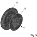
- a mixing block 35 is situated, equipped with mixers 38 , in between which gaps 42 are situated.
- Figure 3 shows a detail of an axonometric view of the mixing block 35 with the rear partition 36 and the front partition 37 .
- Figure 4 shows one mixer 38 in longitudinal section, situated between the rear partition 36 with orifices 46 for the suction of air and the front partition 37 with gaps 42 .
- the mixer 38 is equipped with a confusor 43 and a diffusor 44 .
- the smallest dispersion is attained with the air flow through one mixer 38 of 50 - 70 g/s, but the selected engine 4 with a gas turbine 5 provides for 1.35 -1.5 kg/s, and thus it is necessary to use 33 (thirty three) mixers 38 for the given water flow, and so dimensions of the mixer are selected providing for the air supply from 41 to 45 g/s.
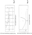
- a through-diameter of the mixer 38 ranging from 10 to 12 mm has been selected ( Figure 6 ) because of the minimum size of droplets of 150 micrometers at the water pressure of 1 - 1.2 MPa and water flow of 60 - 70 l/s, which is ensured by the selected high-pressure water pump 26 .
- the fire extinguishing equipment works as follows:
- Internal diameter (caliber) of the mixer 38 has been selected based on the calculation of the water flow set point. Water consumption is selected based on the proportion of one weight part of air (gas) to 40 - 50 weight parts of water (liquid). Air volume is selected in regard to the required dispersion of droplets. The sizes of droplets range from 100 to 300 ⁇ m.
- the equipment is made ready for work in advance.
- the tank 31 gets filled with foaming agent. If the equipment is not stationary and it is in the required distance from the source of fire, the equipment will be carried into the fire extinguishing zone.
- the engine 4 with a gas turbine 5 is started.
- the engine 4 with a gas turbine 5 is propelled by an electro generator 3 .
- a drive 27 of the high-pressure water pump 26 is started, which will set through the clutch 28 the water pump 26 into operation.
- the high-pressure water pump 26 supplies the extinguishing liquid by pipe from an external source and from the compressor 7 of the engine 1 with a gas turbine 5 compressed air is blown in.
- a mixture of droplets and gas is formed, which gains the operating speed in a gas-dynamic propelling nozzle 20 .
- the fire nozzle 18 is rotated vertically and horizontally using a rotating mechanism 22 .
- the parameters of the gas-dynamic stream can be changed by setting the volume and pressure of supplied liquid, as well as by adjusting the gas flow and pressure by the control unit 2 , which controls the air no-return flap 25 and valve 29 for shutting off water or foam mixture.
- a foaming agent with which the tank 31 is filled is used.
- the valve 32 is opened and the foaming agent gets through the foam mixer 33 together with water into the fire nozzle 18 .
- a foam is formed, which crosses a distance of more than 100 meters, covers the seat of fire and prevents from the access of air.
- the loss of performance of the engine 1 with a gas turbine 5 is compensated by switching on the drive 10 of the water injection pump 9 , which through the water collector 12 starts supplying water through the fine filter 11 and jet 14 into the compressor 7 of the engine 4 with a gas turbine 5 , and through jets 15 .
- the water, which passed through the heat exchanger 17 gets injected as a steam into the combustion chamber 6 of the engine 1 with a gas turbine 5 , and through jets 16 it gets into the stream of exhaust fumes of the engine 1 with a gas turbine, to reduce its temperature.
- the chamber 41 for the supply of air is separated from the chamber 40 for the supply of water by a rear partition 36 of the block 35 of mixers 38 and from the dispersing chamber 39 by a front partition 37 of the block of 35 mixers.
- the mixers 38 are fixed on a rear partition 36 of the mixing block 35 and enter by a gap 42 with the front part into the orifices 42 of the front partition 37 of the block 35 of mixers.
- the mixers 38 are pipe components with flow cross-section selected by way of an experiment.
- Led to the inlet 24 for supply of liquid into the water chamber 40 of the mixing chamber 19 is either water under pressure from the pump 26 , or a mixture of water and foaming agent from the foam mixer 33 , which gets into confusors 43 of the mixers of the block 35 and goes through the cylindrical component 45 of mixers 38 and then through diffusors 44 of the mixers 38 .
- a negative pressure is generated in the mixer 38 , which facilitates air suction through the orifices 46 of mixers 35 from the chamber 41 for the supply of air to the mixing chamber 19 .
- Air/gas comes out of the compressor 7 of the engine 4 with a gas turbine 5 and through an air non-return flap 25 through the compressed air inlet 23 it is led into the air supply chamber 41 of the mixing chamber 19 .
- a part of air goes through the gaps 42 between mixers 35, and through the walls of the orifices 42 of the rear partition 37 of the block 35 of mixers it enters the dispersing chamber 39 of the mixing chamber 19 of the fire nozzle 18 .
- the gaseous medium is divided into two streams: the first one forms a two-phase bubble-structured stream and the second one propels in the gas-dynamic propelling nozzle 20 a high-pressure stream 21 of a dispersive structure.
- the two-phase bubble-structured stream is generated by mixing the first gas stream with a liquid in the cylindrical component 45 or after its prior acceleration for the reduction of pressure in the dispersing chamber 39 of the mixing chamber 19 .
- the bubble stream from each of the diffusers 44 of mixers 38 is led into the dispersing chamber 39 , where intensive destruction takes place and its structure gets changed, possibly generating shock waves, depending on the parameter values, i.e. the bubble structure is transformed to a dispersed structure with the formation of tiny droplets.
- the second stream of gas at the same time enters the dispersing chamber 39 of the mixing chamber 19 of liquid and gas, where a mixture of droplets and gas is formed by mixing the second stream with the dispersed stream.
- the mixture of droplets and gas so formed is led into the gas-dynamic propelling nozzle 20 , where it gains a predetermined speed and on the outlet from the nozzle 20 it forms a high-speed dispersive stream 21 with tiny dispersed droplets.
- the fire fighting nozzle 18 is connected to a screw compressor 50 connected to a diesel engine 47
- FIG. 1B shows a block scheme of the fire extinguishing equipment, with fire nozzle 18 , which is connected to a screw compressor 50 connected to a diesel engine 47 .
- the fire extinguishing equipment is placed on a structural mounting frame 1 , which may be inserted into a classical typified container.
- the fire extinguishing equipment has two basic circuits, a circuit I of air treatment and a circuit II of water and foam treatment,
- the fire extinguishing equipment comprising a fire nozzle 18 with a gas-dynamic propelling nozzle 20 is connected to two basic circuits, specifically the circuit I of air treatment with a diesel engine 47 with a screw compressor 50 and the circuit II of water and foam treatment, comprising a diesel engine 27 connected to a high-pressure pump 26.
- the circuit I of air treatment comprises a fire nozzle 18 connected through the mixing chamber 19 to the inlet 23 of high-pressure air from the compressor 50 .
- This inlet 23 is connected to an air control electromagnetic flow valve 58 , which is through an air non-return flap 25 connected to a screw compressor 50 propelled by a diesel engine 47 .
- the diesel engine 47 is equipped with a generator 48 and an accumulator 49 and with a control and synchronization unit 62 for its control.
- the diesel engine 47 is connected to a fuel system 51 for fuel supply.
- the circuit II of water and foam treatment comprises a fire nozzle 18 connected through the mixing chamber 19 with the supply 24 of water and foam, which is connected to a water and foam mixer 33 .
- the water and foam mixer 33 is connected to an injector 63 and an electromagnetic flow valve 61 of the extinguishing foam, connected to a tank 31 of foaming agent.
- the water and foam mixer 33 is connected to a water control electromagnetic flow valve 54 , connected to a water no-return flap 53 , connected to a high-pressure water pump 26 rotated by a gearbox 52 of the diesel engine 27 .
- the diesel engine 27 is equipped with a generator 3 and an accumulator 59 .
- the diesel engine 27 is controlled by a control and synchronization unit 62 and it is connected to a fuel system 51 for fuel supply.
- the circuit II of water treatment also comprises two water collectors 55 , 56 , and depending on the circumstances it is possible to switch between the two.
- the collector 55 of utility water for the high-pressure pump 26 is connected to a suction strainer 57 (e.g., connected to a pond, river, water reservoir etc.).
- the other collector 56 of drinking water is connected to a municipal water supply network.
- the water filling pump 60 is connected to the high-pressure water pump 26 .
- the fire extinguishing equipment is equipped with a remote control 34 to control the system control unit 2 , connected to a rotating mechanism 22 of the fire nozzle 18 , where the control unit 2 is connected to a thermal image detection 64 , which provides it also with other data.
- FIG. 2 shows a schematic longitudinal section of the fire nozzle 18 .
- the fire nozzle 18 of a cylindrical shape comprises a mixing chamber 19 , which is in the direction of flow, indicated by arrows, divided by a rear partition 36 and a front partition 37 to a chamber 40 for the supply of water, a chamber 41 for the supply of air and a dispersing chamber 39 .
- the chamber 40 is equipped with water and foam supply 24 .
- the chamber 41 is equipped with an inlet 23 of high-pressure air from the compressor 50 .
- the dispersing chamber 39 is narrowed into a gas-dynamic propelling nozzle 20 , from which a high-speed dispersive stream 21 comes out.
- a mixing block 35 is situated, equipped with mixers 38, in between which gaps 42 are situated.
- Figure 3 shows a detail of an axonometric view of the mixing block 35 with the rear partition 36 and the front partition 37 .
- Figure 4 shows one mixer 38 in longitudinal section, situated between the rear partition 36 with orifices 46 for suction of air and the front partition 37 with gaps 42 .
- the mixer 38 is equipped with a confusor 43 and a diffusor 44 .
- the smallest dispersion is attained with the air flow through one mixer 38 of 50 - 70 g/s.
- the selected diesel engine 4 with a screw compressor 50 provides for the flow of 1.35 -1.5 kg/s of high-pressure air and in combination with the diesel engine 27 , which propels the high-pressure pump 26 they make up in terms of volume such a water and air flow, for which it is necessary to use 33 mixers 38 . Therefore the dimensions of the mixer 38 providing for the air supply from 41 to 45 g/s are selected.
- a through-diameter of one mixer 38 ranges, e.g., from 10 to 12 mm and has been selected ( Figure 6 ) because of the minimum size of droplets of 150 micrometers at the water pressure of 1 -1.4 MPa and water flow of 60-70 l/s, which is ensured by the above-mentioned high-pressure water pump 26 .
- Figure 6 shows the dependence of the size of droplets of the extinguishing mixture on the outlet from the mixer 38 in micrometers on the flow diameter of the mixer 38 in millimeters, where these values were obtained by way of an experiment.
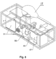
- Figures 7 , 8 show axonometric views of the fire extinguishing equipment partly depicting the internal arrangement of the fire extinguishing equipment.
- Figure 7 shows the fire extinguishing equipment from the side of the high-pressure water pump 26 .
- Figure 8 shows an axonometric view of the fire extinguishing equipment from the opposite side of the compressor 50 .
- Both axonometric views in figures 8 and 9 schematically depict the internal arrangement of the extinguishing technology.
- Figure 9 shows a side view from
- Figure 7 from which it is clear how the fire nozzle 18 is placed on the upper side of the container.
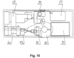
- Figure 10 shows a view from above of the fire extinguishing equipment from Figures 7 and 8 .
- the fire extinguishing equipment works as follows:
- Internal diameter (caliber) of the mixer 38 has been selected based on the calculation of the water flow set point.
- Water consumption is selected based on the proportion of one weight part of air (gas) to 40 - 50 weight parts of water (liquid).
- Air volume is selected in regard to the required dispersion of droplets.
- the sizes of droplets range from 100 to 300 ⁇ m.
- For the given dispersion of droplets an air flow of 50 - 70 g/s is necessary, with the water flow through one mixer 38 in the amount of 2 000 g/s (2 kg/s).
- the fire extinguishing equipment is made ready for work provided by an operating standard as follows:
- the tank 31 gets filled with foaming agent and the fuel system 51 , which provides for the operation of diesel engines 27 , 47 gets filled. If the equipment is not stationary and it is not in the required distance from the source of fire, the equipment will be carried into the fire extinguishing zone.
- the circuit 1 of air treatment gets activated.
- the control unit 2 and the synchronization unit 62 start the diesel engine 47 and start the screw compressor 50 spinning at the necessary speed, required for sufficient air pressure for the air inlet 23 into the mixing chamber 19 .
- the necessary air flow and pressure are evaluated by an air control electromagnetic flow valve 58 .
- On the air pipe an air non-return flap 25 is placed, which prevents from flooding the compressor 50 with water.
- the circuit II of water treatment (lower part of Figure 1B ) gets activated automatically.
- the control unit 2 and the synchronization unit 62 start the diesel engine 27 of the high-pressure water pump 26 , which through a gearbox 52 , sets the water pump 26 into operation.
- Starting the diesel engine 27 is conditional upon flooding the water system by a filling pump 60 either using a collector 55 of utility water and a suction strainer 57 or a direct inlet of drinking water by a collector 56 from a water supply network.
- the high-pressure water pump 26 supplies the extinguishing liquid from an external source and the screw compressor 50 blows compressed air into the mixing chamber 19 . Then a mixture of droplets and gas is formed, which gains the operating speed in a gas-dynamic propelling nozzle 20 , where a high-speed dispersive stream 21 is formed.
- the fire nozzle 18 is rotated vertically and horizontally and rotates using a rotating mechanism 22 .
- the fire extinguishing process is controlled either individually by an operator or automatically using a thermal image detection 64 .
- the parameters of a high-speed gas-dynamic stream 21 can be changed by setting the volume and pressure of supplied liquid, as well as by adjusting the air flow and pressure by the system control unit 2 , which depending on the immediate needs evaluates data from the air electromagnetic flow valve 58 and water control electromagnetic flow valve 54 .
- the control and synchronization unit of diesel engines 62 speeds of both diesel engines (drives) 47 , 62 can be regulated as necessary, and thus changing the performances of both the screw compressor 50 , and the high-pressure pump 26 and this way also changing the parameters and volume of the gas-dynamic stream 21 .
- a foaming agent which fills the tank 31 is used.
- the electromagnetic flow valve 61 is opened and the foaming agent gets through the injector 63 and the foam and water mixer 33 foam into the mixing chamber 19 and together with water it gets into the fire nozzle 18 .
- a foam is thereby formed, which crosses a distance of more than 100 meters, covers the seat of fire and prevents from the access of air.
- the chamber 41 for the supply of air is separated from the chamber 40 for the supply of water by a partition 36 of the block 35 of mixers and from the dispersing chamber 39 by a partition 37 of the block of 35 mixers.
- Mixers 38 are fixed on a partition 36 of the mixing block 35 and enter by the gaps 42 with the front part into the orifices of the partition 37 of the block of mixers.
- the mixers 38 are pipe components of a flow cross-section selected by way of an experiment.
- the gaseous medium is divided into two streams: the first one forms a two-phase bubble-structured stream and the second one propels in the gas-dynamic propelling nozzle 20 a high-pressure stream 21 of a dispersive structure.
- the two-phase bubble-structured stream is generated by mixing the first gas stream with a liquid in the cylindrical component 45 or after its prior acceleration for the reduction of pressure in the dispersing chamber 39 of the mixing chamber 19 .
- the bubble stream from each of the diffusers 44 of mixers 38 is led into the dispersing chamber 39 , where intensive destruction takes place and its structure gets changed, possibly generating shock waves, depending on the parameter values, i.e. the bubble structure is transformed into a dispersed structure, with the formation of tiny droplets.
- the second stream of gas at the same time enters the dispersing chamber 39 of the mixing chamber 19 of liquid and gas, where a mixture of droplets and gas is formed by mixing the second stream with the dispersed stream.
- the mixture of droplets and gas so formed is led into the gas-dynamic propelling nozzle 20 , where it gains a predetermined speed and on the outlet from the nozzle 20 it forms a high-speed dispersive stream 21 with tiny dispersed droplets.
- the number of mixers 38 is determined e.g., as follows:
- a mixing chamber 19 for 33 (thirty three) mixers 38 was designed, with an optimum water flow P w to air flow P a ratio of 40 - 28 established by way of an experiment.
- the mixer 38 consumption was calculated based on a consideration of liquid and gas mixing evenly, which is influenced both by the speed of liquid, and by the pressure and volume of air supplied into the mixing chamber 19 .
- the speed of liquid depends on the cross section and pressure, which is generated by the pump 26 .
- the fire extinguishing equipment with fire fighting nozzle 18 produces a highly dispersed gas-dynamic stream with a reach to a height of up to 80 m high and to a distance of up to 120 m.
Landscapes
- Health & Medical Sciences (AREA)
- Public Health (AREA)
- Business, Economics & Management (AREA)
- Emergency Management (AREA)
- Fire-Extinguishing By Fire Departments, And Fire-Extinguishing Equipment And Control Thereof (AREA)
- Nozzles (AREA)
Claims (13)
- Un équipement d'extinction avec buse (18) d'incendie réalisé sous la forme d'une buse (20) à dynamique gazeuse, reliée à une chambre (19) de mélange avec des entrées (23, 24) d'alimentation en fluide de travail gazeux et en liquide, dans laquelle est disposée une chambre pour la formation d'un écoulement (21) biphasique d'une structure à bulles, est agencée de telle sorte que le équipement d'extinction est équipé d'une pompe (9) à eau et d'un compresseur (7),
caractérisé en ce qu'une chambre (19) de mélange pour la formation d'un écoulement (21) de dispersion biphasique de grande vitesse de structure à bulles est réalisée sous la forme d'un bloc de mélangeurs (35) arrière une cloison (36) avant et une cloison (37) entre, entre lesquels sont disposés des mélangeurs (38) tubulaires, la cloison (36) arrière est disposée dans la chambre avec la possibilité de diviser les entrées (23) pour l'entrée d'air comprimé et l'alimentation (24) pour l'alimentation en liquide comprimé, l'entrée (23) pour l'alimentation en air est situé entre les cloisons (36,37) et l'ouverture d'entrée de chaque mélangeur (38) comporte un confondeur (43) relié à une chambre (40) d'alimentation en eau,les mélangeurs (38) tubulaires sont pourvus d'ouvertures (46) latérales sur le côté de la cloison (36) arrière et les côtés opposés des mélangeurs (38) sont pourvus de diffuseurs (44), les extrémités de sortie des diffuseurs (44) avec fentes (42) sont disposés dans les ouvertures de la cloison (37) avant , etpour le débit total spécifié Pw [l/s] d'eau sous pression Pw [l/s] provenant de la pompe (9) à eau sous pression, le nombre requis de mélangeurs (38) est défini de manière à ce que le débit Pw [l/s] d'eau sous pression Pw [l/s] : dans un mélangeur (38) soit de 1,9 à 2,1 l/s et que le débit Pa [l/s] d'air comprimé provenant du compresseur (7) Pa [l/s] x dans un mélangeur (38) soit de 40 à 28 l/s. - Équipement d'extinction avec buse (18) d'incendie, selon la revendication 1, caractérisé en ce qu'à la sortie de la buse (18) d'incendie, l'écoulement (21) de dispersion de grande vitesse présente une taille de gouttelettes de 100 - 300 µm pour un rapport massique air/eau1 : (40 - 28) et pour un débit d'eau Pa 1,9 - 2,1 l/s à travers un mélangeur (38).
- Équipement d'extinction avec buse (18) d'incendie selon la revendication 1, caractérisé en ce que
la buse (18) d'incendie de forme cylindrique comprend une chambre (19) de mélange qui est divisée dans le sens de l'écoulement par la cloison (36) arrière et la cloison (37) avant en trois chambres (39, 40, 41), à savoir une chambre (40) pour l'alimentation en eau, une chambre (41) pour l'alimentation en air conséquente et une chambre (39) de dispersion conséquente, la chambre (39) de dispersion se rétrécissant en une buse (20) d'entraînement à dynamique gazeuse d'où sort l'écoulement (21) de dispersion de grande vitesse. - Équipement d'extinction avec buse (18) d'incendie selon la revendication 1, caractérisé en ce que
d'équipement dispositif d'extinction contient une unité (2) de commande qui est équipée d'une télécommande (34) et est reliée à un générateur (3) électrique. - Équipement d'extinction avec buse (18) d'incendie selon la revendicatio 1, caractérisé en ce que
la buse (18) d'incendie est reliée à un mécanisme (22) de mouvement pour sa rotation verticale et horizontale. - Équipement d'extinction avec buse (18) d'incendie selon la revendication 1, caractérisé en ce que
l'alimentation (24) en eau ou en mousse de la chambre (19) de mélange est reliée par une pompe (26) à eau à haute pression au réservoir (31) d'un agent moussant. - Équipement d'extinction avec buse (18) d'incendie selon l'une des revendications précédentes 1 à 6, caractérisées en ce que la buse (18) d'incendie est reliée au compresseur (7) du moteur à turbine (4) à gaz.
- Équipement d'extinction avec buse (18) d'incendie selon l'une des revendications précédentes 1 à 6, caractérisées en ce que la buse (18) d'incendie est reliée à un compresseur (50) à vis relié à un moteur (47) diesel.
- Équipement d'extinction avec buse (18) d'incendie selon la revendication 7, caractérisé en ce quela buse (18) d'incendie est relié au compresseur (7) du moteur (4) à turbine à gaz avec la turbine (5) à gaz via un clapet (25) anti-retour d'air,la turbine (5) à gaz est équipée d'une chambre (6) de combustion pour brûler du carburant et d'un échangeur (17) de chaleur pour refroidir la chambre (6) de combustion et la chambre (6) de combustion est reliée au compresseur (7) moteur (4) à turbine à gaz et au système (8) de carburant,la pompe (9) d'injection d'eau étant reliée à des buses (14, 15, 16), à savoir la buse (14) pour pulvériser de l'eau dans le compresseur (7) du moteur (4) à turbine à gaz, de plus étant reliée à la buse (15) pour injecter de la vapeur surchauffée dans la chambre (6) de combustion du moteur (4) à turbine à gaz, et étant également reliée à la buse (16) pourinjecter de l'eau dans les gaz d'échappement du moteur (4) à turbine à gaz.
- Équipement d'extinction avec buse (18) d'incendie selon la revendication 8, caractérisé en ce que
la buse (18) d'incendie est reliée à deux circuits (I, II) de base séparés, à savoir à• un circuit (I) de traitement de l'air avec moteur (47) diesel avec compresseur (50) à vis et à• à un circuit (II) de traitement de l'eau et de la mousse comprenant un moteur (27) diesel relié à une pompe (26) à eau haute pression. - Équipement d'extinction avec buse (18) d'incendie selon la
revendication 10, caractérisé en ce que
le circuit (I) de traitement de l'air comprend une entrée (23) d'air haute pression provenant du compresseur (50), cette entrée (23) est reliée à une vanne (58) électromagnétique de contrôle du débit d'air qui est relié par un clapet (25) anti-retour d'air au compresseur (50) à vis entraîné par un moteur (47) diesel équipé d'un générateur (48) et d'un accumulateur (49), est pourvu d'une unité (62) de commande et de synchronisation et est relié au système d'alimentation (51) en carburant. - Équipement d'extinction avec buse (18) d'incendie selon la revendication 10, caractérisé en ce quele circuit (II) de traitement de l'eau et de la mousse comprend une alimentation (24) en eau et en mousse dans la chambre (19) de mélange, l'alimentation (24) en eau et en mousse est reliée à un mélangeur (33) d'eau et de mousse,le mélangeur (33) d'eau et de mousse est relié à un injecteur (63) et à une vanne (61) électromagnétique de débit de la mousse extinctrice, relié à un réservoir (31) d'agent moussant, et est également relié à une vanne (54) électromagnétique de contrôle du débit d'eau reliée à un clapet (53) anti-retour d'eau relié à une pompe (26) à eau à haute pression reliée à la boîte (52) de vitesses du moteur (27) diesel,le moteur (27) diesel est équipé d'un générateur (3) avec un accumulateur (59), est relié à l'unité (62) de commande et de synchronisation et est également relié au système (51) de carburant,la pompe (26) à eau à haute pression étant reliée au collecteur (55) d'eau sanitaire et au panier (57) d'aspiration ou au collecteur (56) d'eau potable relié au réseau municipal d'approvisionnement en eau.
- Équipement d'extinction avec buse (18) d'incendie selon la revendication 8, caractérisé en ce que
l'équipement d'extinction est doté d'une télécommande (34) pour commander l'unité (2) de commande du système reliée au mécanisme (22) de mouvement de la buse (18) d'incendie, l'unité (2) de commande étant reliée à un système (64) de détection par imagerie thermique.
Applications Claiming Priority (5)
| Application Number | Priority Date | Filing Date | Title |
|---|---|---|---|
| RU2020113289 | 2020-04-10 | ||
| CZ202129A CZ309237B6 (cs) | 2020-04-10 | 2020-11-18 | Hasicí zařízení s požární proudnicí |
| CZ2020616 | 2020-11-18 | ||
| CZ2020661 | 2020-12-09 | ||
| PCT/CZ2021/000004 WO2021204306A1 (fr) | 2020-04-10 | 2021-01-28 | Équipement d'extinction d'incendie avec buse d'incendie |
Publications (2)
| Publication Number | Publication Date |
|---|---|
| EP4132664A1 EP4132664A1 (fr) | 2023-02-15 |
| EP4132664B1 true EP4132664B1 (fr) | 2024-08-07 |
Family
ID=74884772
Family Applications (1)
| Application Number | Title | Priority Date | Filing Date |
|---|---|---|---|
| EP21712414.8A Active EP4132664B1 (fr) | 2020-04-10 | 2021-01-28 | Équipement d'extinction d'incendie avec buse d'incendie |
Country Status (4)
| Country | Link |
|---|---|
| US (1) | US20230142120A1 (fr) |
| EP (1) | EP4132664B1 (fr) |
| CN (1) | CN115666736B (fr) |
| WO (1) | WO2021204306A1 (fr) |
Families Citing this family (2)
| Publication number | Priority date | Publication date | Assignee | Title |
|---|---|---|---|---|
| CN114681845B (zh) * | 2022-04-22 | 2022-11-25 | 海天消防科技股份有限公司 | 一种具有降温作用的变电站细水雾化灭火设备 |
| CN119185868A (zh) * | 2024-11-26 | 2024-12-27 | 泰兴市创诚建设工程有限公司 | 一种建设施工移动消防设备 |
Family Cites Families (22)
| Publication number | Priority date | Publication date | Assignee | Title |
|---|---|---|---|---|
| US2988151A (en) * | 1957-06-21 | 1961-06-13 | Dion-Biro Guy | Foam producing apparatus |
| US4278132A (en) * | 1979-05-21 | 1981-07-14 | Hostetter Morgan D | Proportioning apparatus |
| US4345654A (en) * | 1980-10-06 | 1982-08-24 | Carr Stephen C | Pneumatic atomizing fire fighting supply truck |
| US4492525A (en) * | 1983-02-18 | 1985-01-08 | Grumman Emergency Products, Inc. | Pneumatic fire pump pressure controller |
| US4474680A (en) * | 1983-03-14 | 1984-10-02 | Valerin Technologies Limited | Foam generating apparatus and method |
| US4729434A (en) * | 1986-04-28 | 1988-03-08 | Rohrbach Jerry T | Portable fire-fighting apparatus |
| FR2619023B1 (fr) * | 1987-08-07 | 1991-04-12 | Lamort E & M | Injecteur melangeur sous pression |
| US4981178A (en) * | 1990-03-16 | 1991-01-01 | Bundy Eric D | Apparatus for compressed air foam discharge |
| RU2107554C1 (ru) * | 1996-07-08 | 1998-03-27 | Научно-исследовательский институт низких температур при Московском государственном авиационном институте (техническом университете) | Способ создания газокапельной струи, установка для его осуществления и сопло для создания газокапельной струи |
| RU2132752C1 (ru) * | 1998-04-13 | 1999-07-10 | Научно-исследовательский институт низких температур при МАИ (Московском государственном авиационном институте - техническом университете) | Устройство для создания газокапельной струи и клапан для подачи двухфазной рабочей среды |
| RU2236876C1 (ru) * | 2003-07-21 | 2004-09-27 | Закрытое акционерное общество "СИЛЭН" | Установка для пожаротушения |
| RU2292959C1 (ru) * | 2005-06-08 | 2007-02-10 | Игорь Александрович Лепешинский | Способ создания газокапельной струи и устройство для его осуществления |
| RU2316369C1 (ru) * | 2006-06-22 | 2008-02-10 | Андрей Леонидович Душкин | Устройство пожаротушения |
| DE202006020889U1 (de) * | 2006-10-16 | 2011-01-05 | Neumaerker, Harald, Dr. | Schaumzufuhreinrichtung |
| CN201565019U (zh) * | 2009-09-28 | 2010-09-01 | 江苏卡威专用汽车制造有限公司 | 在高速气体射流中生成泡沫的装置 |
| US9186531B2 (en) * | 2010-04-15 | 2015-11-17 | Elkhart Brass Manufacturing Company, Inc. | Fire fighting monitor |
| US8672234B2 (en) * | 2010-05-20 | 2014-03-18 | Enginetics, Llc | Multi-physics fuel atomizer and methods |
| FR2975917B1 (fr) * | 2011-06-06 | 2014-02-14 | Pok | Dispositif de generation de mousse d'une lance a incendie |
| RU164658U1 (ru) * | 2015-12-22 | 2016-09-10 | Российская Федерация, от имени которой выступает Министерство Российской Федерации по делам гражданской обороны, чрезвычайным ситуациям и ликвидации последствий стихийных бедствий (МЧС России) | Установка пожаротушения |
| RU176037U1 (ru) * | 2015-12-28 | 2017-12-26 | Общество с ограниченной ответственностью Завод пожарных автомобилей "Спецавтотехника" | Устройство для распыления жидкости в газовой среде с образованием двухфазной струи с высокой скоростью и дисперсностью жидкости |
| RU2684305C1 (ru) * | 2018-07-20 | 2019-04-05 | Игорь Александрович Лепешинский | Способ создания газокапельной струи и установка для создания для его осуществления |
| GB2575982A (en) * | 2018-07-30 | 2020-02-05 | Airbus Operations Ltd | Inert gas distribution |
-
2021
- 2021-01-28 WO PCT/CZ2021/000004 patent/WO2021204306A1/fr not_active Ceased
- 2021-01-28 CN CN202180038348.8A patent/CN115666736B/zh active Active
- 2021-01-28 EP EP21712414.8A patent/EP4132664B1/fr active Active
- 2021-01-28 US US17/917,652 patent/US20230142120A1/en active Pending
Also Published As
| Publication number | Publication date |
|---|---|
| US20230142120A1 (en) | 2023-05-11 |
| CN115666736B (zh) | 2024-07-02 |
| CN115666736A (zh) | 2023-01-31 |
| WO2021204306A1 (fr) | 2021-10-14 |
| EP4132664A1 (fr) | 2023-02-15 |
Similar Documents
| Publication | Publication Date | Title |
|---|---|---|
| US5014790A (en) | Method and apparatus for fire control | |
| EP1053935B1 (fr) | Procede d'extinction d'incendies a l'aide d'un aeronef et dispositif s'y rapportant | |
| EP4132664B1 (fr) | Équipement d'extinction d'incendie avec buse d'incendie | |
| CA2578567C (fr) | Buse de lutte contre l'incendie projetant un nuage de brouillard | |
| US5056718A (en) | Jetting nozzle | |
| EP1900438A1 (fr) | Procede de formation d'un jet de gaz et de gouttelettes et dispositif destine a sa realisation | |
| RU84715U1 (ru) | Установка для пожаротушения | |
| RU2236876C1 (ru) | Установка для пожаротушения | |
| RU2130794C1 (ru) | Плавучая установка для пожаротушения и способ ее работы | |
| RU199467U1 (ru) | Пожарный ствол | |
| RU2401681C1 (ru) | Акустический пеногенератор | |
| CZ35531U1 (cs) | Hasicí zařízení s požární proudnicí | |
| RU2037321C1 (ru) | Способ тушения пожаров фонтанов газовых, нефтяных и газонефтяных скважин и установка для его осуществления | |
| CN115382127A (zh) | 一种水雾喷嘴的供水系统 | |
| RU2684305C1 (ru) | Способ создания газокапельной струи и установка для создания для его осуществления | |
| RU2456433C1 (ru) | Способ тушения пожаров фонтанов на газовых, нефтяных и газонефтяных скважинах | |
| RU2853775C1 (ru) | Установка комбинированного тушения пожара воздушно-механической пеной средней кратности с лафетным стволом пены низкой кратности | |
| RU237184U1 (ru) | Устройство комбинированного тушения пожара воздушномеханической пеной средней кратности с лафетным стволом пены низкой кратности | |
| RU2854081C1 (ru) | Установка комбинированного тушения пожара воздушно-механической пеной средней кратности с лафетным стволом пены низкой кратности | |
| RU235713U1 (ru) | Лафетный ствол воздушно-механической пены низкой кратности или распыленной воды | |
| CZ35485U1 (cs) | Hasicí zařízení s požární proudnicí | |
| RU164658U1 (ru) | Установка пожаротушения | |
| RU2118552C1 (ru) | Установка для тушения пожаров | |
| CN2193756Y (zh) | 燃气喷雾水上灭火装置 | |
| RU36239U1 (ru) | Импульсная установка для пожаротушения |
Legal Events
| Date | Code | Title | Description |
|---|---|---|---|
| STAA | Information on the status of an ep patent application or granted ep patent |
Free format text: STATUS: UNKNOWN |
|
| STAA | Information on the status of an ep patent application or granted ep patent |
Free format text: STATUS: THE INTERNATIONAL PUBLICATION HAS BEEN MADE |
|
| PUAI | Public reference made under article 153(3) epc to a published international application that has entered the european phase |
Free format text: ORIGINAL CODE: 0009012 |
|
| STAA | Information on the status of an ep patent application or granted ep patent |
Free format text: STATUS: REQUEST FOR EXAMINATION WAS MADE |
|
| 17P | Request for examination filed |
Effective date: 20221107 |
|
| AK | Designated contracting states |
Kind code of ref document: A1 Designated state(s): AL AT BE BG CH CY CZ DE DK EE ES FI FR GB GR HR HU IE IS IT LI LT LU LV MC MK MT NL NO PL PT RO RS SE SI SK SM TR |
|
| DAV | Request for validation of the european patent (deleted) | ||
| DAX | Request for extension of the european patent (deleted) | ||
| GRAP | Despatch of communication of intention to grant a patent |
Free format text: ORIGINAL CODE: EPIDOSNIGR1 |
|
| STAA | Information on the status of an ep patent application or granted ep patent |
Free format text: STATUS: GRANT OF PATENT IS INTENDED |
|
| INTG | Intention to grant announced |
Effective date: 20231129 |
|
| GRAS | Grant fee paid |
Free format text: ORIGINAL CODE: EPIDOSNIGR3 |
|
| GRAJ | Information related to disapproval of communication of intention to grant by the applicant or resumption of examination proceedings by the epo deleted |
Free format text: ORIGINAL CODE: EPIDOSDIGR1 |
|
| GRAL | Information related to payment of fee for publishing/printing deleted |
Free format text: ORIGINAL CODE: EPIDOSDIGR3 |
|
| STAA | Information on the status of an ep patent application or granted ep patent |
Free format text: STATUS: REQUEST FOR EXAMINATION WAS MADE |
|
| GRAP | Despatch of communication of intention to grant a patent |
Free format text: ORIGINAL CODE: EPIDOSNIGR1 |
|
| STAA | Information on the status of an ep patent application or granted ep patent |
Free format text: STATUS: GRANT OF PATENT IS INTENDED |
|
| INTC | Intention to grant announced (deleted) | ||
| INTG | Intention to grant announced |
Effective date: 20240603 |
|
| RAP3 | Party data changed (applicant data changed or rights of an application transferred) |
Owner name: JETEX INNOVATION S.R.O. |
|
| GRAS | Grant fee paid |
Free format text: ORIGINAL CODE: EPIDOSNIGR3 |
|
| GRAA | (expected) grant |
Free format text: ORIGINAL CODE: 0009210 |
|
| STAA | Information on the status of an ep patent application or granted ep patent |
Free format text: STATUS: THE PATENT HAS BEEN GRANTED |
|
| AK | Designated contracting states |
Kind code of ref document: B1 Designated state(s): AL AT BE BG CH CY CZ DE DK EE ES FI FR GB GR HR HU IE IS IT LI LT LU LV MC MK MT NL NO PL PT RO RS SE SI SK SM TR |
|
| REG | Reference to a national code |
Ref country code: GB Ref legal event code: FG4D |
|
| REG | Reference to a national code |
Ref country code: CH Ref legal event code: EP |
|
| REG | Reference to a national code |
Ref country code: IE Ref legal event code: FG4D |
|
| REG | Reference to a national code |
Ref country code: DE Ref legal event code: R096 Ref document number: 602021016815 Country of ref document: DE |
|
| REG | Reference to a national code |
Ref country code: LT Ref legal event code: MG9D |
|
| REG | Reference to a national code |
Ref country code: NL Ref legal event code: MP Effective date: 20240807 |
|
| PG25 | Lapsed in a contracting state [announced via postgrant information from national office to epo] |
Ref country code: NO Free format text: LAPSE BECAUSE OF FAILURE TO SUBMIT A TRANSLATION OF THE DESCRIPTION OR TO PAY THE FEE WITHIN THE PRESCRIBED TIME-LIMIT Effective date: 20241107 |
|
| REG | Reference to a national code |
Ref country code: AT Ref legal event code: MK05 Ref document number: 1710304 Country of ref document: AT Kind code of ref document: T Effective date: 20240807 |
|
| PG25 | Lapsed in a contracting state [announced via postgrant information from national office to epo] |
Ref country code: GR Free format text: LAPSE BECAUSE OF FAILURE TO SUBMIT A TRANSLATION OF THE DESCRIPTION OR TO PAY THE FEE WITHIN THE PRESCRIBED TIME-LIMIT Effective date: 20241108 Ref country code: NL Free format text: LAPSE BECAUSE OF FAILURE TO SUBMIT A TRANSLATION OF THE DESCRIPTION OR TO PAY THE FEE WITHIN THE PRESCRIBED TIME-LIMIT Effective date: 20240807 Ref country code: PL Free format text: LAPSE BECAUSE OF FAILURE TO SUBMIT A TRANSLATION OF THE DESCRIPTION OR TO PAY THE FEE WITHIN THE PRESCRIBED TIME-LIMIT Effective date: 20240807 Ref country code: FI Free format text: LAPSE BECAUSE OF FAILURE TO SUBMIT A TRANSLATION OF THE DESCRIPTION OR TO PAY THE FEE WITHIN THE PRESCRIBED TIME-LIMIT Effective date: 20240807 Ref country code: PT Free format text: LAPSE BECAUSE OF FAILURE TO SUBMIT A TRANSLATION OF THE DESCRIPTION OR TO PAY THE FEE WITHIN THE PRESCRIBED TIME-LIMIT Effective date: 20241209 |
|
| PG25 | Lapsed in a contracting state [announced via postgrant information from national office to epo] |
Ref country code: BG Free format text: LAPSE BECAUSE OF FAILURE TO SUBMIT A TRANSLATION OF THE DESCRIPTION OR TO PAY THE FEE WITHIN THE PRESCRIBED TIME-LIMIT Effective date: 20240807 |
|
| PG25 | Lapsed in a contracting state [announced via postgrant information from national office to epo] |
Ref country code: LV Free format text: LAPSE BECAUSE OF FAILURE TO SUBMIT A TRANSLATION OF THE DESCRIPTION OR TO PAY THE FEE WITHIN THE PRESCRIBED TIME-LIMIT Effective date: 20240807 |
|
| PG25 | Lapsed in a contracting state [announced via postgrant information from national office to epo] |
Ref country code: AT Free format text: LAPSE BECAUSE OF FAILURE TO SUBMIT A TRANSLATION OF THE DESCRIPTION OR TO PAY THE FEE WITHIN THE PRESCRIBED TIME-LIMIT Effective date: 20240807 Ref country code: IS Free format text: LAPSE BECAUSE OF FAILURE TO SUBMIT A TRANSLATION OF THE DESCRIPTION OR TO PAY THE FEE WITHIN THE PRESCRIBED TIME-LIMIT Effective date: 20241207 |
|
| PG25 | Lapsed in a contracting state [announced via postgrant information from national office to epo] |
Ref country code: HR Free format text: LAPSE BECAUSE OF FAILURE TO SUBMIT A TRANSLATION OF THE DESCRIPTION OR TO PAY THE FEE WITHIN THE PRESCRIBED TIME-LIMIT Effective date: 20240807 |
|
| PG25 | Lapsed in a contracting state [announced via postgrant information from national office to epo] |
Ref country code: ES Free format text: LAPSE BECAUSE OF FAILURE TO SUBMIT A TRANSLATION OF THE DESCRIPTION OR TO PAY THE FEE WITHIN THE PRESCRIBED TIME-LIMIT Effective date: 20240807 Ref country code: RS Free format text: LAPSE BECAUSE OF FAILURE TO SUBMIT A TRANSLATION OF THE DESCRIPTION OR TO PAY THE FEE WITHIN THE PRESCRIBED TIME-LIMIT Effective date: 20241107 |
|
| PG25 | Lapsed in a contracting state [announced via postgrant information from national office to epo] |
Ref country code: RS Free format text: LAPSE BECAUSE OF FAILURE TO SUBMIT A TRANSLATION OF THE DESCRIPTION OR TO PAY THE FEE WITHIN THE PRESCRIBED TIME-LIMIT Effective date: 20241107 Ref country code: PT Free format text: LAPSE BECAUSE OF FAILURE TO SUBMIT A TRANSLATION OF THE DESCRIPTION OR TO PAY THE FEE WITHIN THE PRESCRIBED TIME-LIMIT Effective date: 20241209 Ref country code: PL Free format text: LAPSE BECAUSE OF FAILURE TO SUBMIT A TRANSLATION OF THE DESCRIPTION OR TO PAY THE FEE WITHIN THE PRESCRIBED TIME-LIMIT Effective date: 20240807 Ref country code: NO Free format text: LAPSE BECAUSE OF FAILURE TO SUBMIT A TRANSLATION OF THE DESCRIPTION OR TO PAY THE FEE WITHIN THE PRESCRIBED TIME-LIMIT Effective date: 20241107 Ref country code: NL Free format text: LAPSE BECAUSE OF FAILURE TO SUBMIT A TRANSLATION OF THE DESCRIPTION OR TO PAY THE FEE WITHIN THE PRESCRIBED TIME-LIMIT Effective date: 20240807 Ref country code: LV Free format text: LAPSE BECAUSE OF FAILURE TO SUBMIT A TRANSLATION OF THE DESCRIPTION OR TO PAY THE FEE WITHIN THE PRESCRIBED TIME-LIMIT Effective date: 20240807 Ref country code: IS Free format text: LAPSE BECAUSE OF FAILURE TO SUBMIT A TRANSLATION OF THE DESCRIPTION OR TO PAY THE FEE WITHIN THE PRESCRIBED TIME-LIMIT Effective date: 20241207 Ref country code: HR Free format text: LAPSE BECAUSE OF FAILURE TO SUBMIT A TRANSLATION OF THE DESCRIPTION OR TO PAY THE FEE WITHIN THE PRESCRIBED TIME-LIMIT Effective date: 20240807 Ref country code: GR Free format text: LAPSE BECAUSE OF FAILURE TO SUBMIT A TRANSLATION OF THE DESCRIPTION OR TO PAY THE FEE WITHIN THE PRESCRIBED TIME-LIMIT Effective date: 20241108 Ref country code: FI Free format text: LAPSE BECAUSE OF FAILURE TO SUBMIT A TRANSLATION OF THE DESCRIPTION OR TO PAY THE FEE WITHIN THE PRESCRIBED TIME-LIMIT Effective date: 20240807 Ref country code: ES Free format text: LAPSE BECAUSE OF FAILURE TO SUBMIT A TRANSLATION OF THE DESCRIPTION OR TO PAY THE FEE WITHIN THE PRESCRIBED TIME-LIMIT Effective date: 20240807 Ref country code: BG Free format text: LAPSE BECAUSE OF FAILURE TO SUBMIT A TRANSLATION OF THE DESCRIPTION OR TO PAY THE FEE WITHIN THE PRESCRIBED TIME-LIMIT Effective date: 20240807 Ref country code: AT Free format text: LAPSE BECAUSE OF FAILURE TO SUBMIT A TRANSLATION OF THE DESCRIPTION OR TO PAY THE FEE WITHIN THE PRESCRIBED TIME-LIMIT Effective date: 20240807 |
|
| PG25 | Lapsed in a contracting state [announced via postgrant information from national office to epo] |
Ref country code: SM Free format text: LAPSE BECAUSE OF FAILURE TO SUBMIT A TRANSLATION OF THE DESCRIPTION OR TO PAY THE FEE WITHIN THE PRESCRIBED TIME-LIMIT Effective date: 20240807 Ref country code: DK Free format text: LAPSE BECAUSE OF FAILURE TO SUBMIT A TRANSLATION OF THE DESCRIPTION OR TO PAY THE FEE WITHIN THE PRESCRIBED TIME-LIMIT Effective date: 20240807 |
|
| PG25 | Lapsed in a contracting state [announced via postgrant information from national office to epo] |
Ref country code: EE Free format text: LAPSE BECAUSE OF FAILURE TO SUBMIT A TRANSLATION OF THE DESCRIPTION OR TO PAY THE FEE WITHIN THE PRESCRIBED TIME-LIMIT Effective date: 20240807 |
|
| PG25 | Lapsed in a contracting state [announced via postgrant information from national office to epo] |
Ref country code: SK Free format text: LAPSE BECAUSE OF FAILURE TO SUBMIT A TRANSLATION OF THE DESCRIPTION OR TO PAY THE FEE WITHIN THE PRESCRIBED TIME-LIMIT Effective date: 20240807 |
|
| REG | Reference to a national code |
Ref country code: DE Ref legal event code: R097 Ref document number: 602021016815 Country of ref document: DE |
|
| PLBE | No opposition filed within time limit |
Free format text: ORIGINAL CODE: 0009261 |
|
| STAA | Information on the status of an ep patent application or granted ep patent |
Free format text: STATUS: NO OPPOSITION FILED WITHIN TIME LIMIT |
|
| 26N | No opposition filed |
Effective date: 20250508 |
|
| REG | Reference to a national code |
Ref country code: CH Ref legal event code: PL |
|
| PG25 | Lapsed in a contracting state [announced via postgrant information from national office to epo] |
Ref country code: SE Free format text: LAPSE BECAUSE OF FAILURE TO SUBMIT A TRANSLATION OF THE DESCRIPTION OR TO PAY THE FEE WITHIN THE PRESCRIBED TIME-LIMIT Effective date: 20240807 |
|
| PG25 | Lapsed in a contracting state [announced via postgrant information from national office to epo] |
Ref country code: MC Free format text: LAPSE BECAUSE OF FAILURE TO SUBMIT A TRANSLATION OF THE DESCRIPTION OR TO PAY THE FEE WITHIN THE PRESCRIBED TIME-LIMIT Effective date: 20240807 Ref country code: LU Free format text: LAPSE BECAUSE OF NON-PAYMENT OF DUE FEES Effective date: 20250128 |
|
| GBPC | Gb: european patent ceased through non-payment of renewal fee |
Effective date: 20250128 |
|
| PG25 | Lapsed in a contracting state [announced via postgrant information from national office to epo] |
Ref country code: BE Free format text: LAPSE BECAUSE OF NON-PAYMENT OF DUE FEES Effective date: 20250131 Ref country code: GB Free format text: LAPSE BECAUSE OF NON-PAYMENT OF DUE FEES Effective date: 20250128 |
|
| PG25 | Lapsed in a contracting state [announced via postgrant information from national office to epo] |
Ref country code: FR Free format text: LAPSE BECAUSE OF NON-PAYMENT OF DUE FEES Effective date: 20250131 |
|
| PG25 | Lapsed in a contracting state [announced via postgrant information from national office to epo] |
Ref country code: CH Free format text: LAPSE BECAUSE OF NON-PAYMENT OF DUE FEES Effective date: 20250131 |
|
| REG | Reference to a national code |
Ref country code: BE Ref legal event code: MM Effective date: 20250131 |
|
| PG25 | Lapsed in a contracting state [announced via postgrant information from national office to epo] |
Ref country code: IE Free format text: LAPSE BECAUSE OF NON-PAYMENT OF DUE FEES Effective date: 20250128 |
|
| PG25 | Lapsed in a contracting state [announced via postgrant information from national office to epo] |
Ref country code: IT Free format text: LAPSE BECAUSE OF FAILURE TO SUBMIT A TRANSLATION OF THE DESCRIPTION OR TO PAY THE FEE WITHIN THE PRESCRIBED TIME-LIMIT Effective date: 20240807 |
|
| PGFP | Annual fee paid to national office [announced via postgrant information from national office to epo] |
Ref country code: DE Payment date: 20251229 Year of fee payment: 6 |
|
| PG25 | Lapsed in a contracting state [announced via postgrant information from national office to epo] |
Ref country code: RO Free format text: LAPSE BECAUSE OF FAILURE TO SUBMIT A TRANSLATION OF THE DESCRIPTION OR TO PAY THE FEE WITHIN THE PRESCRIBED TIME-LIMIT Effective date: 20240807 |
|
| PGFP | Annual fee paid to national office [announced via postgrant information from national office to epo] |
Ref country code: CZ Payment date: 20260107 Year of fee payment: 6 |