EP4132681B1 - Filteranordnung und verfahren zum austausch eines filterbeutels - Google Patents
Filteranordnung und verfahren zum austausch eines filterbeutels Download PDFInfo
- Publication number
- EP4132681B1 EP4132681B1 EP21703499.0A EP21703499A EP4132681B1 EP 4132681 B1 EP4132681 B1 EP 4132681B1 EP 21703499 A EP21703499 A EP 21703499A EP 4132681 B1 EP4132681 B1 EP 4132681B1
- Authority
- EP
- European Patent Office
- Prior art keywords
- frame
- filter
- insert
- stretch region
- filter assembly
- Prior art date
- Legal status (The legal status is an assumption and is not a legal conclusion. Google has not performed a legal analysis and makes no representation as to the accuracy of the status listed.)
- Active
Links
Images



Classifications
-
- B—PERFORMING OPERATIONS; TRANSPORTING
- B01—PHYSICAL OR CHEMICAL PROCESSES OR APPARATUS IN GENERAL
- B01D—SEPARATION
- B01D46/00—Filters or filtering processes specially modified for separating dispersed particles from gases or vapours
- B01D46/02—Particle separators, e.g. dust precipitators, having hollow filters made of flexible material
-
- B—PERFORMING OPERATIONS; TRANSPORTING
- B01—PHYSICAL OR CHEMICAL PROCESSES OR APPARATUS IN GENERAL
- B01D—SEPARATION
- B01D29/00—Filters with filtering elements stationary during filtration, e.g. pressure or suction filters, not covered by groups B01D24/00 - B01D27/00; Filtering elements therefor
- B01D29/11—Filters with filtering elements stationary during filtration, e.g. pressure or suction filters, not covered by groups B01D24/00 - B01D27/00; Filtering elements therefor with bag, cage, hose, tube, sleeve or like filtering elements
- B01D29/13—Supported filter elements
- B01D29/23—Supported filter elements arranged for outward flow filtration
- B01D29/27—Filter bags
-
- B—PERFORMING OPERATIONS; TRANSPORTING
- B01—PHYSICAL OR CHEMICAL PROCESSES OR APPARATUS IN GENERAL
- B01D—SEPARATION
- B01D46/00—Filters or filtering processes specially modified for separating dispersed particles from gases or vapours
- B01D46/0002—Casings; Housings; Frame constructions
- B01D46/0005—Mounting of filtering elements within casings, housings or frames
-
- B—PERFORMING OPERATIONS; TRANSPORTING
- B01—PHYSICAL OR CHEMICAL PROCESSES OR APPARATUS IN GENERAL
- B01D—SEPARATION
- B01D46/00—Filters or filtering processes specially modified for separating dispersed particles from gases or vapours
- B01D46/0002—Casings; Housings; Frame constructions
- B01D46/0015—Throw-away type filters
-
- B—PERFORMING OPERATIONS; TRANSPORTING
- B01—PHYSICAL OR CHEMICAL PROCESSES OR APPARATUS IN GENERAL
- B01D—SEPARATION
- B01D46/00—Filters or filtering processes specially modified for separating dispersed particles from gases or vapours
- B01D46/02—Particle separators, e.g. dust precipitators, having hollow filters made of flexible material
- B01D46/023—Pockets filters, i.e. multiple bag filters mounted on a common frame
-
- B—PERFORMING OPERATIONS; TRANSPORTING
- B01—PHYSICAL OR CHEMICAL PROCESSES OR APPARATUS IN GENERAL
- B01D—SEPARATION
- B01D46/00—Filters or filtering processes specially modified for separating dispersed particles from gases or vapours
- B01D46/88—Replacing filter elements
-
- F—MECHANICAL ENGINEERING; LIGHTING; HEATING; WEAPONS; BLASTING
- F24—HEATING; RANGES; VENTILATING
- F24F—AIR-CONDITIONING; AIR-HUMIDIFICATION; VENTILATION; USE OF AIR CURRENTS FOR SCREENING
- F24F13/00—Details common to, or for air-conditioning, air-humidification, ventilation or use of air currents for screening
- F24F13/28—Arrangement or mounting of filters
-
- F—MECHANICAL ENGINEERING; LIGHTING; HEATING; WEAPONS; BLASTING
- F24—HEATING; RANGES; VENTILATING
- F24F—AIR-CONDITIONING; AIR-HUMIDIFICATION; VENTILATION; USE OF AIR CURRENTS FOR SCREENING
- F24F8/00—Treatment, e.g. purification, of air supplied to human living or working spaces otherwise than by heating, cooling, humidifying or drying
- F24F8/10—Treatment, e.g. purification, of air supplied to human living or working spaces otherwise than by heating, cooling, humidifying or drying by separation, e.g. by filtering
- F24F8/108—Treatment, e.g. purification, of air supplied to human living or working spaces otherwise than by heating, cooling, humidifying or drying by separation, e.g. by filtering using dry filter elements
-
- B—PERFORMING OPERATIONS; TRANSPORTING
- B01—PHYSICAL OR CHEMICAL PROCESSES OR APPARATUS IN GENERAL
- B01D—SEPARATION
- B01D2265/00—Casings, housings or mounting for filters specially adapted for separating dispersed particles from gases or vapours
- B01D2265/02—Non-permanent measures for connecting different parts of the filter
- B01D2265/024—Mounting aids
-
- B—PERFORMING OPERATIONS; TRANSPORTING
- B01—PHYSICAL OR CHEMICAL PROCESSES OR APPARATUS IN GENERAL
- B01D—SEPARATION
- B01D2265/00—Casings, housings or mounting for filters specially adapted for separating dispersed particles from gases or vapours
- B01D2265/02—Non-permanent measures for connecting different parts of the filter
- B01D2265/028—Snap, latch or clip connecting means
-
- B—PERFORMING OPERATIONS; TRANSPORTING
- B01—PHYSICAL OR CHEMICAL PROCESSES OR APPARATUS IN GENERAL
- B01D—SEPARATION
- B01D2271/00—Sealings for filters specially adapted for separating dispersed particles from gases or vapours
- B01D2271/02—Gaskets, sealings
-
- B—PERFORMING OPERATIONS; TRANSPORTING
- B01—PHYSICAL OR CHEMICAL PROCESSES OR APPARATUS IN GENERAL
- B01D—SEPARATION
- B01D2279/00—Filters adapted for separating dispersed particles from gases or vapours specially modified for specific uses
- B01D2279/35—Filters adapted for separating dispersed particles from gases or vapours specially modified for specific uses for venting arrangements
Definitions
- the present invention relates to air filters used in buildings. More specifically, the invention relates to bag filters having a frame with a bag-like filter cloth arranged within the frame, which may be used as a unit to be inserted transversely in an air duct or the like.
- a filter bag comprising a filter region and a stretch region.
- the filter region is made of filter material and forms an open upper portion and at least one closed bottom portion.
- the upper portion (14) defines a periphery.
- the stretch region is made of stretchable and/or elastic material different to the filter material.
- the stretch region is provided to and around the periphery of the upper portion of the filter region.
- the stretch region is configured to press against and cover the frame part of a filter assembly according to the first aspect.
- Filter assemblies where the frame is made of wood may be disposed of in environmentally friendly ways by recycling, or they may be burned. Frames made of other materials may also be easily recycled, as the filter insert is removable.
- the frame is provided with parallel intermediate bars across said aperture that defines slots across the aperture.
- the insert may then have multiple bags formed in a pleated fashion having a shared open upper portion and separate closed bottom portions. Each bag may then be arranged to fit into one corresponding slot.
- Fig. 1 a filter assembly 1 according to prior art with a frame 2, intermediate bars 4 and with one filter bag 3 attached 5 between each slot formed by the intermediate bars 4, or at the edges, by an intermediate bar 4 and the frame 2.
- the air flow direction is from the upper or top side of the frame 2 downwards to the bags and the filtered air exits the filter through the bottoms of the bags 3.
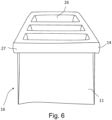
- a frame 6 of a filter assembly 16 according to an embodiment of the present disclosure.
- the frame 6 has the shape of a rectangle or a square, but of course also other shapes are possible, such as a circle.
- the frame 6 comprises a frame part 6.1 having a top side 7a, outer edges 7b, inner edges 7c and a bottom side 7d.
- the top side 7a and the bottom side 7d are on the opposite sides of the frame part 6.1.
- the inner edges 7c define an aperture 26 for a bag-like insert 11 (shown in figs.4 and 5 ).
- the frame 6 comprises intermediate bars 8 extending across the aperture 26.
- the intermediate bars 8 in turn define three slots A, B and C. Obviously, depending on the size, circumstances, and requirements of the filter assembly, the number of slots is a design criteria and may vary from one to any number upwards.
- the outer edges 7b form the outer perimeter of the frame part 6.1.
- the stretch region 27 presses the upper portion 14 against the bottom side 7d, outer edges 7b and/or the top side 7a of the frame part 6.1.
- the insert 11 is fastened to the frame 6 by the pressing force generated by the stretch region 27 against the frame 6, i.e. frame part 6.1 and/or the second frame part 6.2.
Landscapes
- Chemical & Material Sciences (AREA)
- Chemical Kinetics & Catalysis (AREA)
- Engineering & Computer Science (AREA)
- Combustion & Propulsion (AREA)
- Mechanical Engineering (AREA)
- General Engineering & Computer Science (AREA)
- Filtering Of Dispersed Particles In Gases (AREA)
Claims (13)
- Filteranordnung (16), umfassend:- einen Rahmen (6), umfassend eine Oberseite (7a), eine Unterseite (7d), innere Kanten (7c), welche eine Öffnung (26) definieren, und äußere Kanten (7b), welche den äußersten Umfang des Rahmens (6) bilden, und- einen beutelartigen Einsatz (11), welcher Filtermaterial umfasst und einen offenen oberen Abschnitt (14) und zumindest einen geschlossenen unteren Abschnitt aufweist,wobei:- der obere Abschnitt (14) des Einsatzes (11), welcher über den Rahmen (6) gebogen ist, einen Dehnungsbereich (27) aus dehnbarem Material umfasst, und wobei- der Einsatz (11) durch eine von dem Dehnungsbereich (27) gegen den Rahmen (6) erzeugte Anpresskraft an dem Rahmen (6) befestigt wird,dadurch gekennzeichnet, dass der Einsatz (11) in die Öffnung (26) des Rahmens (6) eingesetzt ist, wobei der offene obere Abschnitt (14) über den Rahmen (6) gebogen ist, um die Oberseite (7a), die äußeren Kanten (7b) und zumindest einen Teil der Unterseite (7d) des Rahmens (6) zu bedecken.
- Filteranordnung (16) nach Anspruch 1, wobei der Rahmen (6) vollständig vom Einsatz (11) bedeckt ist.
- Filteranordnung (16) nach Anspruch 1 oder 2, wobei der Dehnungsbereich (27) dazu konfiguriert ist, gegen die Unterseite (7d) des Rahmens (6) zu drücken.
- Filteranordnung (16) nach einem der vorstehenden Ansprüche, wobei der Dehnungsbereich (27) ein elastisches Band, beispielsweise ein Gummiband, umfasst, welches sich um den Umfang des oberen Abschnitts (14) erstreckt.
- Filteranordnung (16) nach einem der vorstehenden Ansprüche, wobei der Rahmen (6) mit parallelen Zwischenstäben (8) über der Öffnung versehen ist, welche Schlitze (A, B, C) über der Öffnung definieren, und wobei der Einsatz (11) mehrere Beutel (12) aufweist, welche in einer gefalteten Weise gebildet sind und einen gemeinsamen offenen oberen Abschnitt (14) und getrennte geschlossene untere Abschnitte aufweisen, und wobei jeder Beutel (12) so angeordnet ist, dass er in einen Schlitz (A, B, C) passt.
- Filteranordnung (16) nach einem der vorstehenden Ansprüche, wobei der Rahmen (6) aus einem starren Material hergestellt ist, welches aus einem der Folgenden ausgewählt ist: Holz, Metall, Polymermaterial, Fiberglas, Kohlefaser oder ein Verbundmaterial, welches ein beliebiges der oben genannten Materialien umfasst.
- Filteranordnung (16) nach einem der vorstehenden Ansprüche, wobei die Filteranordnung (16) zumindest zwei parallele, nebeneinander angeordnete Rahmen (6) und über die Rahmen (6) gebogene Einsätze (11) umfasst, und dass die über die benachbarten Rahmen (6) gebogenen Einsätze (11) einander berühren und so eine Abdichtung zwischen den Rahmen (6) bilden.
- Filteranordnung (16) nach einem der vorstehenden Ansprüche, wobei sich das dehnbare Material des Dehnungsbereichs (27) von dem Filtermaterial unterscheidet.
- Filteranordnung (16) nach einem der vorstehenden Ansprüche, wobei das dehnbare Material eine Mischung aus Nylon und Latex, Gummi oder Spandex umfasst.
- Filteranordnung (16) nach einem der vorstehenden Ansprüche, wobei:- der Einsatz (11) nur durch die von dem Dehnungsbereich (27) gegen den Rahmen (6) erzeugte Anpresskraft an dem Rahmen (6) befestigt wird oder wobei- die entsprechenden Teile des Dehnungsbereichs (27) und der inneren Kante (7c) des Rahmens (6) mit miteinander koppelnden zusätzlichen Befestigungsmitteln versehen sind.
- Filteranordnung (16) nach Anspruch 8, wobei:- das zusätzliche Befestigungsmittel zusammenwirkende Klettbänder oder Schnappverbindungen umfasst, welche an dem Dehnungsbereich (27) und dem Rahmen (6) vorgesehen sind, oder wobei- das zusätzliche Befestigungsmittel eine formschlüssige Verbindung, beispielsweise einen Haken, an dem Dehnungsbereich (27) umfasst, welche zum Einrasten in den Rahmen (6) konfiguriert ist.
- Filteranordnung (16) nach einem der vorstehenden Ansprüche, wobei die Länge des Dehnungsabschnitts (27) in einem Ruhezustand 20 % oder mehr als 20 % kürzer als die Kante des Filtermaterials ist, welche die Öffnung des Einsatzes (11) definiert.
- Verfahren, umfassend:- Entfernen eines Filterbeutels (11), umfassend:- einen Filterbereich aus Filtermaterial, welcher einen offenen oberen Abschnitt (14) und zumindest einen geschlossenen unteren Abschnitt bildet, wobei der obere Abschnitt (14) einen Umfang definiert, und- einen Dehnungsbereich (27) aus dehnbarem und/oder elastischem Material, welches sich von dem Filtermaterial unterscheidet, wobei der Dehnungsbereich (27) an dem und um den äußersten Umfang des oberen Abschnitts (14) des Filterbereichs von einem Rahmen (6) vorgesehen ist,indem zunächst der Dehnungsbereich (27) gedehnt wird und dann der obere Abschnitt (14) des Filterbeutels (11) um den Rahmen (6) herum und der untere Abschnitt des Filterbeutels (11) aus der Öffnung (26) entfernt werden, und- Installieren eines neuen solchen Filterbeutels (11), indem zuerst der untere Abschnitt des Filterbeutels (11) in die Öffnung (26) eingesetzt wird und dann der Dehnungsbereich (27) über und um den Rahmen (6) gedehnt wird, sodass der offene obere Abschnitt (14) über die Oberseite (7a), die äußere Kante (7b), welche den äußersten Umfang des Rahmens (6.1) bilden, und zumindest einen Teil der Unterseite (7d) des Rahmens (6) gebogen wird.
Applications Claiming Priority (2)
| Application Number | Priority Date | Filing Date | Title |
|---|---|---|---|
| FI20205606A FI130153B (fi) | 2020-06-12 | 2020-06-12 | Suodatinkokoonpano |
| PCT/FI2021/050056 WO2021250310A1 (en) | 2020-06-12 | 2021-01-28 | Filter assembly, filter bag and method of replacing a filter bag |
Publications (3)
| Publication Number | Publication Date |
|---|---|
| EP4132681A1 EP4132681A1 (de) | 2023-02-15 |
| EP4132681C0 EP4132681C0 (de) | 2024-07-10 |
| EP4132681B1 true EP4132681B1 (de) | 2024-07-10 |
Family
ID=74553857
Family Applications (1)
| Application Number | Title | Priority Date | Filing Date |
|---|---|---|---|
| EP21703499.0A Active EP4132681B1 (de) | 2020-06-12 | 2021-01-28 | Filteranordnung und verfahren zum austausch eines filterbeutels |
Country Status (9)
| Country | Link |
|---|---|
| US (1) | US12478911B2 (de) |
| EP (1) | EP4132681B1 (de) |
| CN (1) | CN219836243U (de) |
| CA (1) | CA3180170A1 (de) |
| ES (1) | ES2987967T3 (de) |
| FI (1) | FI130153B (de) |
| HU (1) | HUE067934T2 (de) |
| PL (1) | PL4132681T3 (de) |
| WO (1) | WO2021250310A1 (de) |
Families Citing this family (2)
| Publication number | Priority date | Publication date | Assignee | Title |
|---|---|---|---|---|
| CN116585807A (zh) * | 2023-06-20 | 2023-08-15 | 苏州康富特环境科技有限公司 | 一种便于初、中效过滤器安装的连接结构 |
| DE202023001794U1 (de) | 2023-08-24 | 2023-10-13 | Leanfil Oy | Rahmen für einen Luftfilter und Luftfilter |
Citations (1)
| Publication number | Priority date | Publication date | Assignee | Title |
|---|---|---|---|---|
| WO2017210237A1 (en) * | 2016-06-03 | 2017-12-07 | Mia Do | Reusable air filter device |
Family Cites Families (7)
| Publication number | Priority date | Publication date | Assignee | Title |
|---|---|---|---|---|
| NZ270544A (en) * | 1995-02-22 | 1998-01-26 | Filtercorp International Ltd | Packet filter bag header with two rigid frames connected together |
| DE29517898U1 (de) | 1995-11-11 | 1996-12-19 | AEG Hausgeräte GmbH, 90429 Nürnberg | Flusenfilter-Vorrichtung für einen elektrischen Haushalts-Wäschetrockner |
| SE526487C2 (sv) | 2004-03-26 | 2005-09-27 | Fredrik Andersson | Tilluftsdon innefattande flexibel påse av filtermaterial, vilken är lösbart monterad |
| SE528817C2 (sv) | 2005-05-23 | 2007-02-20 | Camfil Ab | Påsfilteraggregat |
| US20080236120A1 (en) | 2007-03-29 | 2008-10-02 | Janet Li | Prefilters for Devices with Air Filter |
| US20090049810A1 (en) | 2007-08-23 | 2009-02-26 | Green Thomas B | Dust filtration bag and frame apparatus and method |
| JP2011161429A (ja) | 2010-02-15 | 2011-08-25 | Shinwa Corp | 袋型エアフィルタ |
-
2020
- 2020-06-12 FI FI20205606A patent/FI130153B/fi active
-
2021
- 2021-01-28 ES ES21703499T patent/ES2987967T3/es active Active
- 2021-01-28 US US18/009,776 patent/US12478911B2/en active Active
- 2021-01-28 CN CN202190000541.8U patent/CN219836243U/zh active Active
- 2021-01-28 CA CA3180170A patent/CA3180170A1/en active Pending
- 2021-01-28 PL PL21703499.0T patent/PL4132681T3/pl unknown
- 2021-01-28 HU HUE21703499A patent/HUE067934T2/hu unknown
- 2021-01-28 WO PCT/FI2021/050056 patent/WO2021250310A1/en not_active Ceased
- 2021-01-28 EP EP21703499.0A patent/EP4132681B1/de active Active
Patent Citations (1)
| Publication number | Priority date | Publication date | Assignee | Title |
|---|---|---|---|---|
| WO2017210237A1 (en) * | 2016-06-03 | 2017-12-07 | Mia Do | Reusable air filter device |
Also Published As
| Publication number | Publication date |
|---|---|
| PL4132681T3 (pl) | 2024-10-21 |
| ES2987967T3 (es) | 2024-11-18 |
| FI130153B (fi) | 2023-03-16 |
| FI20205606A1 (en) | 2021-12-13 |
| EP4132681A1 (de) | 2023-02-15 |
| CN219836243U (zh) | 2023-10-17 |
| US12478911B2 (en) | 2025-11-25 |
| EP4132681C0 (de) | 2024-07-10 |
| WO2021250310A1 (en) | 2021-12-16 |
| US20230294030A1 (en) | 2023-09-21 |
| CA3180170A1 (en) | 2021-12-16 |
| HUE067934T2 (hu) | 2024-11-28 |
Similar Documents
| Publication | Publication Date | Title |
|---|---|---|
| US12478911B2 (en) | Filter assembly, filter bag and method of replacing a filter bag | |
| US6485538B1 (en) | Air-conditioning air filter | |
| US8932380B2 (en) | Dust removal device | |
| JP5580515B2 (ja) | ポケット形エアフィルター | |
| CN208943711U (zh) | 弹性膨胀除尘过滤筒 | |
| JP2011161429A (ja) | 袋型エアフィルタ | |
| CN216129863U (zh) | 一种干衣机及其线屑收集装置 | |
| US8758487B2 (en) | Machine tool mounted mist collector | |
| FI129956B (en) | Filter set | |
| KR101141532B1 (ko) | 차량용 공조장치 | |
| HK1221928A1 (zh) | 空气过滤器和使用该过滤器的空气净化装置 | |
| JP2005240697A (ja) | 扇風機用フィルタ | |
| CN209923528U (zh) | 一种倍捻机辅助除尘可连接设备 | |
| KR20190054269A (ko) | 공기조화기용 에어 믹서 | |
| EP3740394B1 (de) | Wärmetauscheranordnung, schirm und verfahren zum schutz einer wärmetauscheranordnung | |
| JP3688866B2 (ja) | 空気清浄機 | |
| CN102049162A (zh) | 过滤系统 | |
| CN107238157B (zh) | 天井机空气净化装置及天井机 | |
| CN221684728U (zh) | 空气滤网和空气处理设备 | |
| CN115613326B (zh) | 一种干衣机及其线屑收集装置 | |
| CN214529745U (zh) | 一种摇粒机 | |
| CN218880253U (zh) | 一种圆纬机针筒 | |
| CN219020354U (zh) | 一种透气休闲鞋 | |
| CN220238181U (zh) | 一种除尘装置 | |
| KR101679677B1 (ko) | 차량용 공조장치 |
Legal Events
| Date | Code | Title | Description |
|---|---|---|---|
| STAA | Information on the status of an ep patent application or granted ep patent |
Free format text: STATUS: UNKNOWN |
|
| STAA | Information on the status of an ep patent application or granted ep patent |
Free format text: STATUS: THE INTERNATIONAL PUBLICATION HAS BEEN MADE |
|
| PUAI | Public reference made under article 153(3) epc to a published international application that has entered the european phase |
Free format text: ORIGINAL CODE: 0009012 |
|
| STAA | Information on the status of an ep patent application or granted ep patent |
Free format text: STATUS: REQUEST FOR EXAMINATION WAS MADE |
|
| 17P | Request for examination filed |
Effective date: 20221108 |
|
| AK | Designated contracting states |
Kind code of ref document: A1 Designated state(s): AL AT BE BG CH CY CZ DE DK EE ES FI FR GB GR HR HU IE IS IT LI LT LU LV MC MK MT NL NO PL PT RO RS SE SI SK SM TR |
|
| STAA | Information on the status of an ep patent application or granted ep patent |
Free format text: STATUS: EXAMINATION IS IN PROGRESS |
|
| 17Q | First examination report despatched |
Effective date: 20230426 |
|
| DAV | Request for validation of the european patent (deleted) | ||
| DAX | Request for extension of the european patent (deleted) | ||
| GRAP | Despatch of communication of intention to grant a patent |
Free format text: ORIGINAL CODE: EPIDOSNIGR1 |
|
| STAA | Information on the status of an ep patent application or granted ep patent |
Free format text: STATUS: GRANT OF PATENT IS INTENDED |
|
| INTG | Intention to grant announced |
Effective date: 20240408 |
|
| GRAS | Grant fee paid |
Free format text: ORIGINAL CODE: EPIDOSNIGR3 |
|
| GRAA | (expected) grant |
Free format text: ORIGINAL CODE: 0009210 |
|
| STAA | Information on the status of an ep patent application or granted ep patent |
Free format text: STATUS: THE PATENT HAS BEEN GRANTED |
|
| AK | Designated contracting states |
Kind code of ref document: B1 Designated state(s): AL AT BE BG CH CY CZ DE DK EE ES FI FR GB GR HR HU IE IS IT LI LT LU LV MC MK MT NL NO PL PT RO RS SE SI SK SM TR |
|
| REG | Reference to a national code |
Ref country code: CH Ref legal event code: EP |
|
| REG | Reference to a national code |
Ref country code: DE Ref legal event code: R096 Ref document number: 602021015453 Country of ref document: DE |
|
| U01 | Request for unitary effect filed |
Effective date: 20240806 |
|
| U07 | Unitary effect registered |
Designated state(s): AT BE BG DE DK EE FI FR IT LT LU LV MT NL PT SE SI Effective date: 20240820 |
|
| REG | Reference to a national code |
Ref country code: SK Ref legal event code: T3 Ref document number: E 44916 Country of ref document: SK |
|
| REG | Reference to a national code |
Ref country code: ES Ref legal event code: FG2A Ref document number: 2987967 Country of ref document: ES Kind code of ref document: T3 Effective date: 20241118 |
|
| REG | Reference to a national code |
Ref country code: HU Ref legal event code: AG4A Ref document number: E067934 Country of ref document: HU |
|
| PG25 | Lapsed in a contracting state [announced via postgrant information from national office to epo] |
Ref country code: GR Free format text: LAPSE BECAUSE OF FAILURE TO SUBMIT A TRANSLATION OF THE DESCRIPTION OR TO PAY THE FEE WITHIN THE PRESCRIBED TIME-LIMIT Effective date: 20241011 |
|
| PG25 | Lapsed in a contracting state [announced via postgrant information from national office to epo] |
Ref country code: IS Free format text: LAPSE BECAUSE OF FAILURE TO SUBMIT A TRANSLATION OF THE DESCRIPTION OR TO PAY THE FEE WITHIN THE PRESCRIBED TIME-LIMIT Effective date: 20241110 |
|
| PG25 | Lapsed in a contracting state [announced via postgrant information from national office to epo] |
Ref country code: HR Free format text: LAPSE BECAUSE OF FAILURE TO SUBMIT A TRANSLATION OF THE DESCRIPTION OR TO PAY THE FEE WITHIN THE PRESCRIBED TIME-LIMIT Effective date: 20240710 |
|
| PG25 | Lapsed in a contracting state [announced via postgrant information from national office to epo] |
Ref country code: RS Free format text: LAPSE BECAUSE OF FAILURE TO SUBMIT A TRANSLATION OF THE DESCRIPTION OR TO PAY THE FEE WITHIN THE PRESCRIBED TIME-LIMIT Effective date: 20241010 |
|
| PG25 | Lapsed in a contracting state [announced via postgrant information from national office to epo] |
Ref country code: RS Free format text: LAPSE BECAUSE OF FAILURE TO SUBMIT A TRANSLATION OF THE DESCRIPTION OR TO PAY THE FEE WITHIN THE PRESCRIBED TIME-LIMIT Effective date: 20241010 Ref country code: IS Free format text: LAPSE BECAUSE OF FAILURE TO SUBMIT A TRANSLATION OF THE DESCRIPTION OR TO PAY THE FEE WITHIN THE PRESCRIBED TIME-LIMIT Effective date: 20241110 Ref country code: HR Free format text: LAPSE BECAUSE OF FAILURE TO SUBMIT A TRANSLATION OF THE DESCRIPTION OR TO PAY THE FEE WITHIN THE PRESCRIBED TIME-LIMIT Effective date: 20240710 Ref country code: GR Free format text: LAPSE BECAUSE OF FAILURE TO SUBMIT A TRANSLATION OF THE DESCRIPTION OR TO PAY THE FEE WITHIN THE PRESCRIBED TIME-LIMIT Effective date: 20241011 |
|
| U20 | Renewal fee for the european patent with unitary effect paid |
Year of fee payment: 5 Effective date: 20250121 |
|
| PG25 | Lapsed in a contracting state [announced via postgrant information from national office to epo] |
Ref country code: SM Free format text: LAPSE BECAUSE OF FAILURE TO SUBMIT A TRANSLATION OF THE DESCRIPTION OR TO PAY THE FEE WITHIN THE PRESCRIBED TIME-LIMIT Effective date: 20240710 |
|
| PLBE | No opposition filed within time limit |
Free format text: ORIGINAL CODE: 0009261 |
|
| STAA | Information on the status of an ep patent application or granted ep patent |
Free format text: STATUS: NO OPPOSITION FILED WITHIN TIME LIMIT |
|
| 26N | No opposition filed |
Effective date: 20250411 |
|
| PG25 | Lapsed in a contracting state [announced via postgrant information from national office to epo] |
Ref country code: MC Free format text: LAPSE BECAUSE OF FAILURE TO SUBMIT A TRANSLATION OF THE DESCRIPTION OR TO PAY THE FEE WITHIN THE PRESCRIBED TIME-LIMIT Effective date: 20240710 |
|
| REG | Reference to a national code |
Ref country code: CH Ref legal event code: U11 Free format text: ST27 STATUS EVENT CODE: U-0-0-U10-U11 (AS PROVIDED BY THE NATIONAL OFFICE) Effective date: 20260201 |
|
| U20 | Renewal fee for the european patent with unitary effect paid |
Year of fee payment: 6 Effective date: 20260107 |
|
| PGFP | Annual fee paid to national office [announced via postgrant information from national office to epo] |
Ref country code: HU Payment date: 20260123 Year of fee payment: 6 |
|
| PGFP | Annual fee paid to national office [announced via postgrant information from national office to epo] |
Ref country code: GB Payment date: 20260123 Year of fee payment: 6 |
|
| PGFP | Annual fee paid to national office [announced via postgrant information from national office to epo] |
Ref country code: ES Payment date: 20260227 Year of fee payment: 6 |
|
| PGFP | Annual fee paid to national office [announced via postgrant information from national office to epo] |
Ref country code: NO Payment date: 20260123 Year of fee payment: 6 Ref country code: IE Payment date: 20260122 Year of fee payment: 6 |
|
| PG25 | Lapsed in a contracting state [announced via postgrant information from national office to epo] |
Ref country code: RO Free format text: LAPSE BECAUSE OF FAILURE TO SUBMIT A TRANSLATION OF THE DESCRIPTION OR TO PAY THE FEE WITHIN THE PRESCRIBED TIME-LIMIT Effective date: 20240710 |
|
| PGFP | Annual fee paid to national office [announced via postgrant information from national office to epo] |
Ref country code: CZ Payment date: 20260121 Year of fee payment: 6 Ref country code: CH Payment date: 20260201 Year of fee payment: 6 |
|
| PGFP | Annual fee paid to national office [announced via postgrant information from national office to epo] |
Ref country code: PL Payment date: 20260119 Year of fee payment: 6 |
|
| PGFP | Annual fee paid to national office [announced via postgrant information from national office to epo] |
Ref country code: SK Payment date: 20260123 Year of fee payment: 6 |