EP4132685B1 - Verfahren und anordnung zur erfassung von kohlendioxid aus einem gasstrom mit einem adsorptionssystem mit einer wärmespeicher- und rückgewinnungseinheit - Google Patents
Verfahren und anordnung zur erfassung von kohlendioxid aus einem gasstrom mit einem adsorptionssystem mit einer wärmespeicher- und rückgewinnungseinheit Download PDFInfo
- Publication number
- EP4132685B1 EP4132685B1 EP21723437.6A EP21723437A EP4132685B1 EP 4132685 B1 EP4132685 B1 EP 4132685B1 EP 21723437 A EP21723437 A EP 21723437A EP 4132685 B1 EP4132685 B1 EP 4132685B1
- Authority
- EP
- European Patent Office
- Prior art keywords
- air
- adsorbent bed
- adsorbent
- heat storage
- conduit
- Prior art date
- Legal status (The legal status is an assumption and is not a legal conclusion. Google has not performed a legal analysis and makes no representation as to the accuracy of the status listed.)
- Active
Links
Images


Classifications
-
- B—PERFORMING OPERATIONS; TRANSPORTING
- B01—PHYSICAL OR CHEMICAL PROCESSES OR APPARATUS IN GENERAL
- B01D—SEPARATION
- B01D53/00—Separation of gases or vapours; Recovering vapours of volatile solvents from gases; Chemical or biological purification of waste gases, e.g. engine exhaust gases, smoke, fumes, flue gases, aerosols
- B01D53/02—Separation of gases or vapours; Recovering vapours of volatile solvents from gases; Chemical or biological purification of waste gases, e.g. engine exhaust gases, smoke, fumes, flue gases, aerosols by adsorption, e.g. preparative gas chromatography
- B01D53/04—Separation of gases or vapours; Recovering vapours of volatile solvents from gases; Chemical or biological purification of waste gases, e.g. engine exhaust gases, smoke, fumes, flue gases, aerosols by adsorption, e.g. preparative gas chromatography with stationary adsorbents
- B01D53/0407—Constructional details of adsorbing systems
- B01D53/0438—Cooling or heating systems
-
- B—PERFORMING OPERATIONS; TRANSPORTING
- B01—PHYSICAL OR CHEMICAL PROCESSES OR APPARATUS IN GENERAL
- B01D—SEPARATION
- B01D53/00—Separation of gases or vapours; Recovering vapours of volatile solvents from gases; Chemical or biological purification of waste gases, e.g. engine exhaust gases, smoke, fumes, flue gases, aerosols
- B01D53/02—Separation of gases or vapours; Recovering vapours of volatile solvents from gases; Chemical or biological purification of waste gases, e.g. engine exhaust gases, smoke, fumes, flue gases, aerosols by adsorption, e.g. preparative gas chromatography
- B01D53/06—Separation of gases or vapours; Recovering vapours of volatile solvents from gases; Chemical or biological purification of waste gases, e.g. engine exhaust gases, smoke, fumes, flue gases, aerosols by adsorption, e.g. preparative gas chromatography with moving adsorbents, e.g. rotating beds
-
- B—PERFORMING OPERATIONS; TRANSPORTING
- B01—PHYSICAL OR CHEMICAL PROCESSES OR APPARATUS IN GENERAL
- B01D—SEPARATION
- B01D53/00—Separation of gases or vapours; Recovering vapours of volatile solvents from gases; Chemical or biological purification of waste gases, e.g. engine exhaust gases, smoke, fumes, flue gases, aerosols
- B01D53/02—Separation of gases or vapours; Recovering vapours of volatile solvents from gases; Chemical or biological purification of waste gases, e.g. engine exhaust gases, smoke, fumes, flue gases, aerosols by adsorption, e.g. preparative gas chromatography
- B01D53/04—Separation of gases or vapours; Recovering vapours of volatile solvents from gases; Chemical or biological purification of waste gases, e.g. engine exhaust gases, smoke, fumes, flue gases, aerosols by adsorption, e.g. preparative gas chromatography with stationary adsorbents
- B01D53/0407—Constructional details of adsorbing systems
- B01D53/0446—Means for feeding or distributing gases
-
- B—PERFORMING OPERATIONS; TRANSPORTING
- B01—PHYSICAL OR CHEMICAL PROCESSES OR APPARATUS IN GENERAL
- B01D—SEPARATION
- B01D53/00—Separation of gases or vapours; Recovering vapours of volatile solvents from gases; Chemical or biological purification of waste gases, e.g. engine exhaust gases, smoke, fumes, flue gases, aerosols
- B01D53/02—Separation of gases or vapours; Recovering vapours of volatile solvents from gases; Chemical or biological purification of waste gases, e.g. engine exhaust gases, smoke, fumes, flue gases, aerosols by adsorption, e.g. preparative gas chromatography
- B01D53/04—Separation of gases or vapours; Recovering vapours of volatile solvents from gases; Chemical or biological purification of waste gases, e.g. engine exhaust gases, smoke, fumes, flue gases, aerosols by adsorption, e.g. preparative gas chromatography with stationary adsorbents
- B01D53/0462—Temperature swing adsorption
-
- B—PERFORMING OPERATIONS; TRANSPORTING
- B01—PHYSICAL OR CHEMICAL PROCESSES OR APPARATUS IN GENERAL
- B01D—SEPARATION
- B01D53/00—Separation of gases or vapours; Recovering vapours of volatile solvents from gases; Chemical or biological purification of waste gases, e.g. engine exhaust gases, smoke, fumes, flue gases, aerosols
- B01D53/14—Separation of gases or vapours; Recovering vapours of volatile solvents from gases; Chemical or biological purification of waste gases, e.g. engine exhaust gases, smoke, fumes, flue gases, aerosols by absorption
-
- B—PERFORMING OPERATIONS; TRANSPORTING
- B01—PHYSICAL OR CHEMICAL PROCESSES OR APPARATUS IN GENERAL
- B01D—SEPARATION
- B01D53/00—Separation of gases or vapours; Recovering vapours of volatile solvents from gases; Chemical or biological purification of waste gases, e.g. engine exhaust gases, smoke, fumes, flue gases, aerosols
- B01D53/26—Drying gases or vapours
- B01D53/261—Drying gases or vapours by adsorption
-
- F—MECHANICAL ENGINEERING; LIGHTING; HEATING; WEAPONS; BLASTING
- F24—HEATING; RANGES; VENTILATING
- F24F—AIR-CONDITIONING; AIR-HUMIDIFICATION; VENTILATION; USE OF AIR CURRENTS FOR SCREENING
- F24F3/00—Air-conditioning systems in which conditioned primary air is supplied from one or more central stations to distributing units in the rooms or spaces where it may receive secondary treatment; Apparatus specially designed for such systems
- F24F3/12—Air-conditioning systems in which conditioned primary air is supplied from one or more central stations to distributing units in the rooms or spaces where it may receive secondary treatment; Apparatus specially designed for such systems characterised by the treatment of the air otherwise than by heating and cooling
- F24F3/14—Air-conditioning systems in which conditioned primary air is supplied from one or more central stations to distributing units in the rooms or spaces where it may receive secondary treatment; Apparatus specially designed for such systems characterised by the treatment of the air otherwise than by heating and cooling by humidification; by dehumidification
-
- B—PERFORMING OPERATIONS; TRANSPORTING
- B01—PHYSICAL OR CHEMICAL PROCESSES OR APPARATUS IN GENERAL
- B01D—SEPARATION
- B01D2253/00—Adsorbents used in seperation treatment of gases and vapours
- B01D2253/10—Inorganic adsorbents
- B01D2253/106—Silica or silicates
- B01D2253/108—Zeolites
-
- B—PERFORMING OPERATIONS; TRANSPORTING
- B01—PHYSICAL OR CHEMICAL PROCESSES OR APPARATUS IN GENERAL
- B01D—SEPARATION
- B01D2257/00—Components to be removed
- B01D2257/50—Carbon oxides
- B01D2257/504—Carbon dioxide
-
- B—PERFORMING OPERATIONS; TRANSPORTING
- B01—PHYSICAL OR CHEMICAL PROCESSES OR APPARATUS IN GENERAL
- B01D—SEPARATION
- B01D2257/00—Components to be removed
- B01D2257/80—Water
-
- B—PERFORMING OPERATIONS; TRANSPORTING
- B01—PHYSICAL OR CHEMICAL PROCESSES OR APPARATUS IN GENERAL
- B01D—SEPARATION
- B01D2258/00—Sources of waste gases
- B01D2258/02—Other waste gases
- B01D2258/0283—Flue gases
-
- B—PERFORMING OPERATIONS; TRANSPORTING
- B01—PHYSICAL OR CHEMICAL PROCESSES OR APPARATUS IN GENERAL
- B01D—SEPARATION
- B01D2258/00—Sources of waste gases
- B01D2258/05—Biogas
-
- B—PERFORMING OPERATIONS; TRANSPORTING
- B01—PHYSICAL OR CHEMICAL PROCESSES OR APPARATUS IN GENERAL
- B01D—SEPARATION
- B01D2258/00—Sources of waste gases
- B01D2258/06—Polluted air
-
- B—PERFORMING OPERATIONS; TRANSPORTING
- B01—PHYSICAL OR CHEMICAL PROCESSES OR APPARATUS IN GENERAL
- B01D—SEPARATION
- B01D2259/00—Type of treatment
- B01D2259/65—Employing advanced heat integration, e.g. Pinch technology
- B01D2259/655—Employing advanced heat integration, e.g. Pinch technology using heat storage materials
-
- B—PERFORMING OPERATIONS; TRANSPORTING
- B01—PHYSICAL OR CHEMICAL PROCESSES OR APPARATUS IN GENERAL
- B01D—SEPARATION
- B01D53/00—Separation of gases or vapours; Recovering vapours of volatile solvents from gases; Chemical or biological purification of waste gases, e.g. engine exhaust gases, smoke, fumes, flue gases, aerosols
- B01D53/02—Separation of gases or vapours; Recovering vapours of volatile solvents from gases; Chemical or biological purification of waste gases, e.g. engine exhaust gases, smoke, fumes, flue gases, aerosols by adsorption, e.g. preparative gas chromatography
-
- Y—GENERAL TAGGING OF NEW TECHNOLOGICAL DEVELOPMENTS; GENERAL TAGGING OF CROSS-SECTIONAL TECHNOLOGIES SPANNING OVER SEVERAL SECTIONS OF THE IPC; TECHNICAL SUBJECTS COVERED BY FORMER USPC CROSS-REFERENCE ART COLLECTIONS [XRACs] AND DIGESTS
- Y02—TECHNOLOGIES OR APPLICATIONS FOR MITIGATION OR ADAPTATION AGAINST CLIMATE CHANGE
- Y02C—CAPTURE, STORAGE, SEQUESTRATION OR DISPOSAL OF GREENHOUSE GASES [GHG]
- Y02C20/00—Capture or disposal of greenhouse gases
- Y02C20/40—Capture or disposal of greenhouse gases of CO2
-
- Y—GENERAL TAGGING OF NEW TECHNOLOGICAL DEVELOPMENTS; GENERAL TAGGING OF CROSS-SECTIONAL TECHNOLOGIES SPANNING OVER SEVERAL SECTIONS OF THE IPC; TECHNICAL SUBJECTS COVERED BY FORMER USPC CROSS-REFERENCE ART COLLECTIONS [XRACs] AND DIGESTS
- Y02—TECHNOLOGIES OR APPLICATIONS FOR MITIGATION OR ADAPTATION AGAINST CLIMATE CHANGE
- Y02P—CLIMATE CHANGE MITIGATION TECHNOLOGIES IN THE PRODUCTION OR PROCESSING OF GOODS
- Y02P60/00—Technologies relating to agriculture, livestock or agroalimentary industries
- Y02P60/20—Reduction of greenhouse gas [GHG] emissions in agriculture, e.g. CO2
Definitions
- the present invention relates to a method for the capture and subsequent storage of CO 2 from a CO 2 source ranging from sources with extremely low concentrations such as ambient air, via sources with higher concentrations such as air from vegetable storage spaces to sources with relatively high concentrations such as flue gas from combustion processes.
- the product contains up to more than 90% CO 2 , and no use of chemicals in any form ensures safety. Energy consumption is minimized by means disclosed here.
- the present invention relates to the enhancement of a clean adsorption method and process for CO 2 capture, by maximization of the adsorbent CO 2 storage capacity combined with storage and re-use of heat required in the process, providing energy savings, and thus extending the range of useful applications.
- WO2018/034570 presented a system for closed or semi-closed greenhouses.
- the closing of the greenhouse is accomplished by extracting air at a high rate from the closed greenhouse, dehumidifying it, adjusting the temperature, adding supplementary CO 2 captured from the outside air, and subsequently returning this CO 2 enriched air to the greenhouse. This stabilizes the greenhouse temperature and humidity and eliminates possibilities for CO 2 emissions.
- Plant transpiration in greenhouses increases the relative humidity in the local air. About 90% of the humidity taken up by plants is used for transpiration while 10% is used for growth. The transpiration cools the plant to 2° C or more below the ambient temperature. The rate of transpiration is a function of, among other factors, the radiative heat input and the air relative humidity. High relative humidity, near water vapour saturation in the local air, reduces transpiration. If the temperature then drops, water may precipitate on plant leaves and elsewhere. This increases the risk of fungal diseases. Low relative humidity, such as below 50% in combination with high temperature, may result in excessive transpiration rates. The plant may then start to close the stomata openings, through which transpiration occurs, to reduce transpiration. However, CO 2 uptake also occurs through the stomata openings, so this may restrict plant growth. It is important to maintain the local air relative humidity at acceptable if not optimum levels.
- Plant growth rate depends heavily on light including solar radiation or artificial lights. Solar radiation up to at least 600W/m 2 benefits the plants. Artificial light provides about 250 to 300W/m 2 and is used whenever the solar radiation is insufficient. However, both sources of light also provide heat and thus affect the greenhouse temperature. The optimum temperature depends on plant species and time of day. Day temperature of 20 to 25° C is suitable for most plants. Optimum night temperatures may be in the range from 15 to 18° C. Typically, the heat input is too high during sunny days and as a result, greenhouse hatches are opened. This helps reduce the temperature and humidity.
- the opening of the hatches also reduces the concentration of CO 2 and this may hamper plant growth rate. The depletion may happen very quickly, within minutes.
- Greenhouses with artificial CO 2 addition such as from liquid CO 2 tanks, typically operate with CO 2 concentrations in the range from 600 to 800 ppm. With open hatches this drops to about 400 ppm. Up to three quarters of all CO 2 artificially injected into the greenhouse is emitted. This is costly and reduces plant growth rates. It limits the economic optimum CO 2 concentration in the greenhouse; without such emissions the optimum CO 2 concentration might have been much higher such as 1200 ppm.
- the earlier invention, WO2018/034570 solves these issues. Further work with this technology has uncovered new areas where the technology disclosed in can provide great benefits.
- One example is vegetable storage facilities, where the air tends to become too CO 2 rich, such as for example 10 000 ppm, caused by slow vegetable degradation.
- the CO 2 capture technology, WO2018/034570 could solve this problem by closing the storage facility and capturing excess CO 2 . The question if the capture system could capture CO 2 from flue gas, typically containing 40 000 ppm CO 2 , has also been raised.
- DAC Direct Air Capture
- CO 2 capture systems from sources where the CO 2 is at least partly mixed with components from air and are not pressurized, are usually tailor made to the CO 2 source.
- CO 2 from flue gas is typically captured by adsorption using a reactive amine solution.
- the main issue with this is amine degradation in the presence of oxygen, forming carcinogenic compounds such as nitrosamines.
- WO 2013075981 A3 describes a method for extracting CO 2 from air by adsorption on a solid adsorbent.
- the solid sorbent is functionalized using amine compounds that react with CO2. These chemicals enhance the adsorption capacity and reduce adsorbent sensitivity to humidity.
- the amine compounds are exposed to hot air with high concentrations of oxygen, causing potential degradation to toxic and possibly carcinogenic products. CO 2 from such sources can therefore not be used in the enclosed space of a greenhouse. Performance during long term operation is uncertain, and functionalized solid sorbents may not be commercially available.
- non-functionalized adsorbents that are available commercially zeolites, as used in WO2018/034570 , are among the most promising.
- Zeolites have some very significant advantages. CO 2 capture is extremely fast even from dilute sources such as air. Zeolites consist of pure aluminium and silicon oxides. These are inert and safe compounds, much as natural rocks. Zeolites are commercially available from numerous manufacturers and proven. They are suitable for DAC and also CO 2 sources with higher CO 2 concentrations than air.
- H 2 O is preferentially adsorbed. If the zeolite contains more than 2 to 4 weight% H 2 O, the capacity to adsorb CO 2 is reduced. However, if there is moisture in the air or gas containing CO 2 , this moisture will be adsorbed quickly at the zeolite bed inlet. Further into the zeolite bed CO 2 may still be adsorbed. The overall effect is a slightly reduced capacity to store CO 2 , while the ability to quickly adsorb CO 2 further into the zeolite bed is less affected.
- It is an object of the present invention is to provide a method and an arrangement for efficient capture of CO 2 , temporarily store the captured CO 2 and release the CO 2 as nearly 100% CO 2 following the adsorption sequence.
- the invention shall not introduce any new contaminants in the produced CO 2 or in the exhaust air.
- An additional object is to reduce energy consumption, in particular high value energy such as electric or high temperature (above 80 to 100°C) to an absolute minimum.
- the adsorbent shall be used as efficiently as possible, requiring the least amount for a pre-defined CO 2 capture capacity. Beyond this, the latest commercially available technologies, including air handling, which is developing rapidly to reduce energy consumption, shall be utilized to the extent possible.
- the invention shall have the capability to work with varying CO 2 concentrations in the incoming gas, from as low as 50 ppm (which may be desirable in greenhouses during the night) via 400 ppm as in ambient air and 10 000 ppm as in vegetable storage facilities, to 40 000 ppm as in flue gas from combustion engines.
- humidity and “absolute humidity” are used as a measure of the true water vapour content of air (g/m3).
- relative humidity of an air-water vapour mixture is used as a measure of the ratio of the actual partial pressure of water vapour in the air to the partial pressure of water vapour in the air if the air had been saturated at the temperature in question.
- CO2 concentration is a measure of the number of molecules of CO 2 in the air relative to the total number of gas molecules in the air. It is measured in ppm or parts per million.
- the pressure is herein given in the unit “bara” is “bar absolute”. Accordingly, 1.013 bara is the normal atmospheric pressure at sea level. In SI units, 1 bar corresponds to 100 kPa.
- ambient temperature may differ with the climate for operation of a closed or semi-closed system served by a process according to the present invention. Normally, the ambient temperature is from about 0 to 40 °C, but the ambient temperature may also be from sub-zero levels to somewhat higher than 40°C, such as 50 °C.
- FIG. 1 is a principle overall sketch of a system according to a preferred embodiment of the present invention.
- Part 1 is a process for air cooling and de-humidification and re-heating after CO2 capture, comprising two desiccant wheels and a heat exchanger illustrated as a heat exchange wheel.
- the desiccant wheels are for air de-humidification.
- the heat exchange wheel is for air re-heating after CO 2 capture, preserving energy.
- Part 2 is the CO 2 capture system with zeolite bed, CO 2 desorption gas circulation system, heat storage and CO 2 storage.
- Part 1 air cooling and de-humidification with subsequent re-heating, comprises an air inlet conduit 1 where ambient air enters the process driven by a not shown fan.
- This air may be pre-cooled in a cooler 3 before proceeding to a first desiccant wheel 9.
- the desiccant wheel comprises a rotating cylinder, typically 10 to 30 cm thick, where the air passes over a water adsorbent such as silica gel.
- the cylinder has two sections 19 and 8, the first used for air dehydration and the second used for adsorbent regeneration.
- the sections are shown as 270° for dehydration and 90° for regeneration, but this is for illustration purposes and may vary depending on system design. As an example, 180° for dehydration and 180° for regeneration may also be used.
- the air gets in contact with or in close proximity to the adsorbent.
- the adsorbent physically adsorbs humidity according to known equilibria between amount of humidity adsorbed and partial pressure of humidity in the air.
- the air pressure drop through the desiccant wheel is very low, in the order of 100Pa.
- the slow rotation of the wheel perhaps 10 revolutions per hour, continually moves the humid adsorbent exposed to air from the moisture adsorption section 19 to the regeneration section 8 and after regeneration back to the section 19.
- the air flows in a conduit 20 via a cooler 16 and a conduit 52 to a second desiccant wheel 14. Similar to the desiccant wheel 9 this cylinder may be 10 to 30 cm thick and there is a 270° moisture adsorption section 22 and 90° regeneration or desorption section 13. Silica gel is typically used as desiccant. In the section 22 most of the humidity in the air from the desiccant wheel 9 is removed.
- the partial pressure of H 2 O in the air exiting the wheel, conduit 17 leading to the process part 2 shall be such that no water precipitation or ice forms in downstream low temperature processes. Typically, this means water dew point in the range -30 to -60°C, preferably about -50°C.
- Dry air returning from the process part 2, conduit 25, is slightly colder than the air going to the process part 2, the conduit 17. This air flows via a small side draw, a conduit 21, typically zero or a few percent of the air in the conduit 25, and then in a conduit 24 to a second side draw, a conduit 5. Air flow in the conduit 5 may be from about one third to two thirds or more of the air in the conduit 25.
- This dry air flows to a heater 6 where it is heated to typically 50 to 100°C, with preferred temperature in the range 60 to 80°C. After heating, this air flows in a conduit 7 to the regeneration section 13 of desiccant wheel 14.
- the remaining amount of humidity in the adsorbent is such that, as the adsorbent moves with the rotating wheel into the water adsorption section 22, the adsorbent is capable of reducing the H 2 O dew point in the conduit 17 to desired values, about -30 to -60°C.
- Energy for H 2 O removal in the section 13, essentially vaporization energy for the H 2 O removed from the adsorbent, is supplied as sensible heat in the air from the heater 6.
- the regeneration air flows in the conduit 12 to a point of mixing with small amounts of extra air from the conduit 21. This reduces the relative humidity of the resulting air mixture, which next flows in a conduit 11 to a heater 10.
- the air is trim heated, as required, to desired temperature which, similar to air in the conduit 12, is in the range 35 to 55°C or higher such as 60 to100°C.
- the air flows in a conduit 15 to the adsorbent regeneration section 8 of desiccant wheel 9.
- H 2 O is removed from the desiccant.
- the shift progresses to a level sufficient for required air dehydration as the desiccant moves with the revolving wheel into the adsorption section 19.
- the regeneration energy in desiccant wheel 9 is supplied as sensible heat in regeneration air from the conduit 15. The amount of energy required is determined by the vaporization energy of the H 2 O removed from the adsorbent.
- Moist regeneration air at a temperature slightly higher than the temperature of the ambient air, is returned to the atmosphere. Excess dry air from the process part 2, a conduit 2, is also returned to the atmosphere or may alternatively be utilized in a not shown vaporization chilling unit for the supply of low temperature coolant to for example coolers 3 or 16.
- Figure 1 part 2 shows a process for the reception of dehydrated air from part 1, cooling of this air, adsorption and desorption of CO2, re-heat of the dehydrated air and return of this air to the process part 1.
- Air from the conduit 17 is cooled in a heat exchange wheel 18, section 23.
- the air flows through passages in the wheel and gets in close contact with cold substance, such as a metal, in these openings. This cools the air and at the same time heats the wheel heat storage substance.
- the wheel rotates slowly, thus moving heated heat storage substance from partition 23 to partition 26 of the wheel, where the wheel heat storage material is re-cooled by cold air from a conduit 33. In this process, the air from the conduit 33 is heated. It exits the heat exchange wheel 18, section 26, in the conduit 25.
- the heat exchange wheel 18 can be replaced by an air - air heat exchanger.
- the temperature is typically in the range -25 to -45°C.
- the air is trim cooled in a heat exchanger 29 by heat exchange with a coolant provided by a not shown heat pump. After trim cooling, in a conduit 38, the air is about 2 to 5°C colder than in the conduit 28.
- This air may bypass downstream equipment via a valve 30, enabling the continued operation of the upstream air dehydration and cooling process whenever the downstream CO 2 capture process does not need air, such as during CO 2 desorption.
- the process downstream of the conduit 38 has four operating modes. These are CO 2 adsorption at low temperature in an adsorbent bed 34 located in a container 35, heating of the adsorbent bed, desorption of CO 2 from the adsorbent bed and re-cooling of the adsorbent bed before the cycle is repeated.
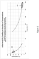
- FIG. 2 shows typical range for low temperature and high adsorbent loading operation, 63, of this operation.
- the adsorbent bed adsorbs virtually all CO 2 from the air.
- the duration of the adsorption process may be from less than one and up to several hours.
- Figure 3 , part 1, graph 59 shows spatial variation in the air temperature within the adsorbent bed during CO 2 adsorption.
- the temperature is low, in the range from -10 to -50°C, and increases slightly, perhaps by roughly 1°C, from the bed inlet to the bed outlet.
- the air flow which is large especially when adsorbing CO 2 from lean air as opposed to for example flue gas, flows downwards through the CO 2 adsorbent beads. This prevents fluidization of the beads.
- CO 2 depleted air from the adsorbent bed 34 is directed via the exit conduit 36 and a valve 37 to the return conduit 33.
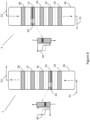
- FIG. 5 parts 1 and 2 shows compact designs of the adsorbent beds and adsorbent container 35. Air from the conduit 32 flows to two adsorbent beds stacked in a vertical direction, arranged for parallel air flow, such that equal fractions of the total air flows through each bed. An air exit conduit 36 may be on the opposite side of the air inlet flow 32, as shown in Figure 5 part 1, or, for very compact designs, on the same side as shown in part 2.
- Figure 5 shows two adsorbent beds arranged vertically, but larger numbers of vertically stacked beds such as 3, 4, 5 or more is possible.
- the heating is accomplished by gas, a mixture of air and CO 2 , flowing from the warm side 58 of a combined high and low temperature heat storage system 54, 55, 56, 57 and 58.
- This gas flows via a conduit 53, a conduit 46 and trim heater 41, a conduit 42, the valve 37 and the conduit 36 to the adsorbent bed 34, thus heating the adsorbent bed.
- the flow direction through the adsorbent bed is the opposite of the direction used during the first operation mode, adsorption.
- FIG. 3 part 2 illustrates this.
- a transition zone 67 receives warm air from below. When the warm air encounters colder adsorbent beads, the beads are warmed and the air is cooled. Thus, at the inlet of the transition zone, the adsorbent beads reach nearly the same temperature as the warm incoming air. In the transition zone the air transfers heat to the beads and is cooled in the process.
- the key phenomenon is that the adsorbent beads are heated to nearly the temperature of the warm incoming air, thus preserving the valuable high temperature heat of the air.
- the air going out of the adsorbent bed will be at the low temperature originally in the bed, thus preserving the valuable low temperature heat originally in the adsorbent bed, until the transition zone reaches the end of the bed. It is thus possible to store this coldness for later use. As shown in Figure 6 part 1 this is done in the stacked heat storage beds 54 to 58, located within a container 66.
- the cold heat transfer gas flows via the conduit 32, the valve 31 now adjusted for the second operating mode, via a fan 43, a conduit 44, through a valve 49 to a conduit 51.
- the stacked heat storage bed receives cold air from the conduit 51.
- the beds contain metal or ceramic heat storage material with large surface area such as beads with diameters 3 to 10mm.
- the cold air and CO 2 from the conduit 51 flows through bed 54, then to the bed 55 which contains an upwards moving temperature transition zone 65, with temperature profile as shown in graph 69.
- This transition zone could also be in beds 54, 56, 57 or 58 but not at the top end of the bed 58. This depends on the size of the heat storage and the system operation. People skilled in the art will also understand that the exact shape of the transition zone depends on air flow rate end temperature, heat transfer to and from the heat storage medium and the amount and heat capacity of heat storage medium.
- Air from the transition zone is warm. As the air flows through beds 56, 57 and 58 it stays warm and thus supplies heat to the CO 2 adsorbent bed 34 via the conduits 53 and 46, the trim heater 41, the conduit 42, the valve 37 and the conduit 36. The overall effect of this process is to move valuable coldness from the adsorbent bed 34 to the heat storage 66, while at the same time moving heat from the heat storage 66 to the adsorbent bed 34. This continues until the CO 2 adsorbent bed is warm and ready for the third operating mode.
- CO 2 adsorbent heating After completion of the second operating mode, CO 2 adsorbent heating, the third operating mode, CO 2 desorption, starts.
- Warm air from the adsorbent 34 flows via the conduit 32, in opposite way of the arrow shown in Figure 1 , via the valve 31 to the conduit 40.
- valve 31 Similar to the second operating mode, valve 31 allows flow from conduit 32 to conduit 40, but is closed to conduit 39.
- the gas flows from the conduit 40 via the fan 43 and the conduit 44 to the valve 49. This valve is adjusted such the gas can flow to a conduit 45 but not to the conduit 51.
- Gas from the conduit 45 is directed via conduit 46 to the trim heater 41. Small amounts of heat are provided in the heater 41 to compensate for CO 2 desorption heat requirement, typically around 30kJ/mole CO 2 .
- any water remaining in air from the adsorbent wheel 14 that has been adsorbed in the adsorbent 34 is removed and requires some extra heat, about 4 kJ/g.
- the temperature profile within the adsorbent bed 34 during CO 2 desorption is indicated in Figure 4 , part 1. The temperature is high and nearly constant especially towards the end of the desorption cycle, as shown in graph 60. CO 2 desorption proceeds until the temperature is in the range 260 to 300°C as indicated in Figure 2 , area 64.
- CO 2 storage 47 This storage may preferably be of the inflatable type.
- the process switches to the fourth operating mode, adsorbent bed cooling.
- the adsorbent bed is cooled to the temperature required for CO 2 adsorption.
- This procedure is somewhat similar to the second mode of operation, adsorbent bed heating, but the gas now flows in the opposite direction.
- the cooling is accomplished by gas, a mixture of air and CO 2 , flowing from the cold side 54 of the combined high and low temperature heat storage system 54, 55, 56, 57 and 58. This gas flows via the conduit 51, the valve 49, the conduit 44 and the fan 43, via the conduit 40, the valve 31 and the conduit 32 to the adsorbent bed 34.
- the flow direction through the adsorbent bed is the same as used during the first operation mode, adsorption. Similar to operating mode 2, instead of gradually cooling the whole adsorbent bed the bed will be cooled to nearly the temperature of the incoming cold gas in initially a heat transfer zone near the gas inlet into the bed.
- FIG. 4 This temperature transition effect is shown in Figure 4 , part 2, graphs 62 and 62'.
- Graph 62 shows the temperature transition zone at some time into the heating process, graph 61' at a later time. This transition zone occurs initially at the bed inlet. As cooling progresses, it moves gradually into the bed until it finally reaches the end at the bottom of the bed.
- graph 62 shows, gas from the CO 2 adsorbent transition zone is warm, very near the temperature of the adsorption bed before cooling started. This high temperature is preserved for later bed heating by directing the warm gas via the conduit 36, through the valve 37 in a direction to the conduit 42 and the trim heater 41, via conduits 46 and 53, to the warm storage side of heat storage system 54 to 58.
- this incoming warm air pushes air through the heat storage system.
- transition zone 65' As the air reaches a cold - hot transition zone, shown in Figure 6 part 2, transition zone 65', it is cooled to nearly the temperature required for the cooling of the adsorbent bed 34.
- Figure 6 shows the transition zone in heat storage bed 57 but could typically be in the heat storage beds 56 or, towards the end of the adsorbent cooling operation, bed 55 or some distance into bed 54 but not at the end of this bed. Below the transition zone the air is cold. The cold air flows via the conduit 51, the valve 49, the conduit 44, the fan 43, the conduit 40, the valve 31 and the conduit 32 back to the adsorbent bed 34.
- the warm - cold transition zone in the heat storage system has been pushed from the warm end bed 58 towards the cold end bed 54 but not through the cold end bed 54 all the way to the outlet of this unit, the conduit 51.
- the direction of movement of the warm - cold transition zone is shown in Figure 6 part 2, transition zone 65' and graph 70.
- the first operating mode can start, repeating the cycle.
- FIG. 7 shows a second embodiment of the invention.
- a second CO 2 adsorption unit 35' is connected in parallel to the first unit 35.
- the operation of the second unit is similar to the operation of the unit 35. Operation may be by alternating CO 2 adsorption between the two units.
- one of the units, for example the unit 35' is in the first operating mode, receiving cold and dry air through a conduit 39', a valve 31' and a conduit 32'.
- CO 2 and H 2 O depleted air is routed via a conduit 36' and a valve 37' to the conduit 33.
- the other unit, 35 goes through operating modes two, three and four. In this way, the cold and dry air supply may operate continuously and may therefore be smaller in order to supply a specified amount of CO 2 .
- the heat storage may be smaller than would be required according to Figure 1 .
- This example will follow the four operating modes. As before, these are CO 2 adsorption at low temperature in an adsorbent bed 34 located in a container 35, heating of the adsorbent bed, desorption of CO 2 from the adsorbent bed and re-cooling of the adsorbent bed before the cycle is repeated.
- the initial state before the CO 2 adsorption starts is the same as the state after the completion of the fourth operating mode.
- the CO 2 adsorbent bed has been cooled and high temperature heat is stored in the heat storage 54 to 58.
- the CO 2 adsorbent contains about 15 g residual CO 2 per kg CO 2 adsorbent from a previous run.
- the example refers mainly to the Figure 1 .
- the adsorption of the H 2 O in the desiccant wheel is exothermic and the temperature of the air in the conduit 20 is about 33°C. This air is cooled to 15°C in the cooler 16 and then forwarded via the conduit 52 to the desiccant wheel 14, section 22.
- This air flows in conduits 25 and 24, with no side draw in the conduit 21.
- One third of the air about 10 kg/h, flows via the conduit 5 to the heater 6 where it is heated to about 90°C. Subsequently it flows via the conduit 7 to the desiccant wheel 14, regeneration section 13.
- the air exits the regeneration section 13 in the conduit 12 at a temperature of about 60°C.
- the H 2 O flow with the air is about 477kg/h.
- the air is then re-heated to 90°C in the heater 10 and enters the desiccant wheel 9, regeneration section 8 via the conduit 15. Downstream the regeneration, the conduit 4, the temperature has dropped to about 39°C and the H 2 O flow with the air is about 1331kg/h.
- the table below shows a summary of the desiccant wheel operation.
- the stream numbers refer to Figure 1 , part 1.
- Silica gel is used as H 2 O adsorbent.
- the objective is to show that in the example, air entering and exiting the desiccant wheel regeneration sections has a lower amount of water adsorbed in the silica gel than the air entering and exiting the adsorption sections. Therefore, the regeneration air will regenerate the desiccant wheel adsorbent by removing water. In this process, the temperature of the air drops from the air inlet to the air outlet.
- operating mode 2 is initiated by adjusting the valve 31 such that there is free flow between the conduits 32 and 40, but no flow into the valve from the conduit 39. Instead, cold air may be bypassed via the valve 30 or the complete cold air supply may be stopped.
- the CO 2 adsorbent will contain about 80g CO2 per kg adsorbent. After desorption of CO 2 , with a CO 2 partial pressure of 1.0 bar and desorption temperature about 280°C, there will be a residual amount of about 15g CO 2 per kg adsorbent. In this example, the net amount of CO 2 adsorbed will be 65g per kg CO 2 . People skilled in the art will understand that with lower partial pressure CO 2 , such as if diluted by air, or higher desorption temperature such as up to 300°C, the residual amount of CO 2 in the adsorbent can be much lower.
- the adsorption and storage of 600kg CO 2 Based on 65g CO 2 per kg adsorbent, the adsorption and storage of 600kg CO 2 , about 9 metric tons of adsorbent is required. 10 metric tons will be assumed in this example, corresponding to about 12.5m 3 adsorbent beads. Furthermore, the volume of the 30kg/s air flow at -45°C is about 23.5m 3 /s. With superficial air velocity of 0.6m/s the total area of adsorbent becomes roughly 40m 2. Combined with the adsorbent volume of 12.5m3, the thickness of the adsorbent bed is about 0.31m.
- the heating of 10 metric tons of adsorbent, heat will be supplied from the heat storage 54 to 58, stored in an earlier run, by flowing 30 kg/s gas from the heat storage 58 via the trim heater 41, through the adsorbent bed 34 where the gas gives off heat to the adsorbent and is cooled to the adsorbent temperature of near -45°C such as shown in Figure 3 part 2 graphs 61 and 61'.
- the cooled gas flows via the fan 43 to the cold end of the heat storage 54 - 58, cooling the cold end and thus preserving the low temperature and pushing more hot gas from the heat storage 58 to the adsorbent bed 34.
- the third operating mode CO 2 desorption starts. CO 2 and air flow out of the CO 2 adsorbent 34 via the conduit 32, the valve 31, the conduit 40, the fan 43 which enforces the gas flow and then via the conduits 45 and 46 to the trim heater 41 where heat is supplied for the CO 2 and any H 2 O desorption.
- the warmed gas then flows via the conduit 42, the valve 37 and the conduit 36 to the adsorbent 34. This continues until the required amount of CO 2 , 600 kg, is desorbed. The duration of this operation may in the order of one hour depending on the heat input in the heater 41 and the gas circulation rate. Desorbed CO 2 , about 600 kg, flows via the conduit 48, the valve 50 and the cooler 65 to the CO 2 storage 47.
- operating mode 4 CO 2 adsorbent cooling, starts.
- This is similar to the operating mode 2, but the air flowing between the heat storage 66 and the CO 2 adsorbent unit 35 now flows in the opposite direction, with cold gas flowing from the heat storage via the conduit 51 and downstream equipment to the CO 2 adsorbent 34.
- the gas is heated by remaining heat from the CO 2 desorption.
- This warm gas flows via the conduit 36 to the heat storage 66, heating heat storage beds near the top by pushing a heat transfer zone towards the cold end of the heat storage.
- cold gas from the cold end of the heat storage is pushed to the CO 2 adsorbent bed 34, further cooling this bed.
- the operating mode four is completed and the system is again ready to start with operating mode 1.
Landscapes
- Chemical & Material Sciences (AREA)
- Engineering & Computer Science (AREA)
- Analytical Chemistry (AREA)
- General Chemical & Material Sciences (AREA)
- Oil, Petroleum & Natural Gas (AREA)
- Chemical Kinetics & Catalysis (AREA)
- Combustion & Propulsion (AREA)
- Mechanical Engineering (AREA)
- General Engineering & Computer Science (AREA)
- Drying Of Gases (AREA)
- External Artificial Organs (AREA)
- Solid-Sorbent Or Filter-Aiding Compositions (AREA)
Claims (11)
- Verfahren zum Erfassen von CO2 aus einer CO2-Quelle, wie z. B. Umgebungsluft oder Rauchgasen, mit den folgenden Schritten:a) Leiten eines Stroms der Luft/Gase durch ein Bett (34) aus CO2-Adsorptionsmaterial, wobei CO2 aus der geströmten Luft/Gas in dem CO2-Adsorptionsmittelbett erfasst wird,b) Leiten eines Heizgasstroms durch eine Wärmespeicher- und -rückgewinnungseinheit (66) und das CO2-Adsorptionsmittelbett (34), wobei gespeicherte Wärme von der Wärmespeicher- und -rückgewinnungseinheit (66) auf das CO2-Adsorptionsmittelbett (34) übertragen wird,c) Leiten des Heizgases mittels eines Gebläses (43) aus dem CO2-Adsorptionsmittelbett (34) durch eine Begleitheizung (41) und zurück durch das CO2-Adsorptionsmittelbett (34), Desorbieren von CO2 aus dem CO2-Adsorptionsmittelbett (34), Extrahieren des desorbierten CO2,d) Leiten eines Kühlgasstroms durch die Wärmespeicher- und -rückgewinnungseinheit (66) und das CO2-Adsorptionsmittelbett (34), wobei Wärme vom CO2-Adsorptionsmittelbett (34) an die Wärmespeicher- und - rückgewinnungseinheit (66) übertragen wird.
- Verfahren nach Anspruch 1, wobei in Schritt a) der Strom der Luft/Gase durch das Bett (34) aus CO2-Adsorptionsmaterial in einer ersten Richtung geleitet wird, in Schritt b) der Strom des Heizgases durch die Wärmespeicher- und -rückgewinnungseinheit (66) und das CO2-Adsorptionsmittelbett (34) in einer zweiten, der ersten Richtung entgegengesetzten Richtung geleitet wird, und in Schritt d) der Strom des Kühlgases durch die Wärmespeicher- und -rückgewinnungseinheit und das CO2-Adsorptionsmittelbett in der ersten Richtung geleitet wird.
- Verfahren nach Anspruch 1 oder 2, wobei der Strom von Umgebungsluft oder Rauchgasen vor dem Leiten in das CO2-Adsorptionsmittelbett getrocknet und gekühlt wird.
- Verfahren nach Anspruch 3, wobei die Gase durch ein erstes Trockenmittelrad (9) und dann durch einen Wärmetauscher (18) geleitet werden, bevor sie in das CO2-Adsorptionsmittelbett geleitet werden, und der Gasausstoß aus dem CO2-Adsorptionsmittelbett durch den Wärmetauscher und das erste Trockenmittelrad zurückgeführt wird.
- Verfahren nach Anspruch 3, wobei die Gase durch ein erstes Trockenmittelrad (9) und dann durch ein zweites Trockenmittelrad (14) und einen Wärmetauscher (18) geleitet werden, bevor sie in das CO2-Adsorptionsmittelbett geleitet werden, und der Gasausstoß aus dem CO2-Adsorptionsmittelbett durch den Wärmetauscher und das erste Trockenmittelrad und das zweite Trockenmittelrad zurückgeführt wird.
- Anordnung zum Erfassen von CO2 aus einer CO2-Quelle, wie z. B. Umgebungsluft oder Rauchgasen, nach dem in den Ansprüchen 1-5 beanspruchten Verfahren, wobei die Anordnung umfasst:einen CO2-Erfassungsbehälter (35) mit einem CO2-Adsorptionsmittelbett (34), das dazu eingerichtet ist, CO2 während des Adsorptionsschritts a zu adsorbieren und CO2 während des Desorptionsschritts c zu desorbieren,dadurch gekennzeichnet, dass die Anordnung ferner eine Wärmespeicher- und -rückgewinnungseinheit (66) umfasst, die dazu eingerichtet ist, gespeicherte Wärme vor dem Desorptionsschritt an das CO2-Adsorptionsmittelbett zu übertragen und nach dem Desorptionsschritt Wärme aus dem CO2-Adsorptionsmittelbett zurückzugewinnen,eine Einlassleitung (39), die mit einer ersten Öffnung eines ersten Dreiwegeventils (31) verbunden ist, wobei eine Eingangsleitung (32) des CO2-Erfassungsbehälters (35) mit einer zweiten Öffnung des ersten Ventils (31) verbunden ist, eine Ausgangsleitung (36) des Behälters (35) mit einer ersten Öffnung eines zweiten Dreiwegeventils (37) verbunden ist, eine zweite Öffnung des zweiten Dreiwegeventils (37) mit einer Auslassleitung (33) verbunden ist, eine dritte Öffnung des ersten Dreiwegeventils (31) mit einer ersten Öffnung eines dritten Dreiwegeventils (49) verbunden ist, eine zweite Öffnung des dritten Dreiwegeventils (49) mit einer ersten Öffnung der Wärmespeicher- und Rückgewinnungseinheit (66) verbunden ist, eine zweite Öffnung der Wärmespeicher- und Rückgewinnungseinheit (66) mit einer dritten Öffnung des zweiten Dreiwegeventils (37) verbunden ist, eine Umgehungsleitung (45) eine dritte Öffnung des dritten Dreiwegeventils (49) mit der zweiten Öffnung der Wärmespeicher- und Rückgewinnungseinheit (66) verbunden ist, die Anordnung ferner eine Umwälzpumpe (43), die entweder an der dritten Öffnung des ersten Dreiwegeventils (31) oder an der dritten Öffnung des zweiten Dreiwegeventils (37) installiert ist, eine Begleitheizung (41), die an der dritten Öffnung des zweiten Dreiwegeventils (37) installiert ist, und eine CO2-Auslassleitung (48) mit einem Auslassventil (50) umfasst.
- Anordnung nach Anspruch 6, wobei das CO2-Adsorptionsmittelbett (34) Zeolithmaterial enthält.
- Anordnung nach Anspruch 6 oder 7, wobei die Wärmespeicher- und -rückgewinnungseinheit (66) mehrere Betten (54, 55, 56, 57, 58) aus einem Wärmespeichermedium enthält.
- Anordnung nach Anspruch 8, wobei das Wärmespeichermedium Perlen aus einem metallischen oder keramischen Wärmespeichermaterial mit großer Oberfläche enthält.
- Anordnung nach einem der Ansprüche 6 bis 9, wobei eine Gaseinlassleitung (1) mit einem Trocknungseingang eines ersten Trockenmittelrades (9) verbunden ist, dessen Trocknungsausgang mit einem ersten Seiteneingang eines Wärmetauschers (18) verbunden ist, dessen erster Seitenausgang mit der Einlassleitung (39) verbunden ist, die Auslassleitung (33) mit einem zweiten Seiteneingang des Wärmetauschers (18) verbunden ist, der zweite Seitenausgang des Wärmetauschers (18) mit einer Gasauslassleitung (25, 24, 2) verbunden ist, und wobei ein Rückgewinnungseingang des ersten Trockenmittelrades (9) mit den Gasauslassleitungen 24, 25 verbunden ist.
- Anordnung nach Anspruch 10, wobei ein zweites Trockenmittelrad (14) zwischen dem ersten Trockenmittelrad (9) und dem Wärmetauscher (18) installiert ist.
Applications Claiming Priority (2)
| Application Number | Priority Date | Filing Date | Title |
|---|---|---|---|
| NO20200431A NO346496B1 (en) | 2020-04-07 | 2020-04-07 | A method and arrangement for capturing CO2 |
| PCT/NO2021/050095 WO2021206564A1 (en) | 2020-04-07 | 2021-04-07 | A method and arrangement for capturing carbon dioxide from a gas stream using an adsorption system comprising a heat storage and recovery unit |
Publications (3)
| Publication Number | Publication Date |
|---|---|
| EP4132685A1 EP4132685A1 (de) | 2023-02-15 |
| EP4132685C0 EP4132685C0 (de) | 2024-05-15 |
| EP4132685B1 true EP4132685B1 (de) | 2024-05-15 |
Family
ID=75787188
Family Applications (1)
| Application Number | Title | Priority Date | Filing Date |
|---|---|---|---|
| EP21723437.6A Active EP4132685B1 (de) | 2020-04-07 | 2021-04-07 | Verfahren und anordnung zur erfassung von kohlendioxid aus einem gasstrom mit einem adsorptionssystem mit einer wärmespeicher- und rückgewinnungseinheit |
Country Status (5)
| Country | Link |
|---|---|
| US (1) | US20230137348A1 (de) |
| EP (1) | EP4132685B1 (de) |
| CA (1) | CA3173632A1 (de) |
| NO (1) | NO346496B1 (de) |
| WO (1) | WO2021206564A1 (de) |
Families Citing this family (24)
| Publication number | Priority date | Publication date | Assignee | Title |
|---|---|---|---|---|
| EP4166215A1 (de) * | 2021-10-12 | 2023-04-19 | TotalEnergies OneTech | Kohlendioxidentfernungsanlage und zugehöriges verfahren |
| DE102021130001A1 (de) * | 2021-11-17 | 2023-05-17 | Audi Aktiengesellschaft | Verwertung von Kohlendioxid aus der Umgebungsluft |
| DE102021130002A1 (de) | 2021-11-17 | 2023-05-17 | Audi Aktiengesellschaft | Verwertung von Kohlendioxid aus der Umgebungsluft |
| CN114294039B (zh) * | 2021-12-14 | 2023-12-22 | 天地科技股份有限公司 | 一种煤矿风井中无功耗二氧化碳多路回收装置 |
| JP2025502002A (ja) | 2022-01-04 | 2025-01-24 | カリフォルニア インスティチュート オブ テクノロジー | 低co2含有供給源から二酸化炭素を捕捉するための金属含有mor型ゼオライトおよびその使用方法 |
| CN114588754B (zh) * | 2022-03-02 | 2023-04-21 | 百年控股(深圳)有限公司 | 一种用于空气二氧化碳捕集和压缩的装置及方法 |
| CN115382350B (zh) * | 2022-03-16 | 2024-11-29 | 浙江天采云集科技股份有限公司 | 一种从混合气中回收co2的全温程模拟旋转移动床变压吸附工艺 |
| EP4499266A1 (de) * | 2022-03-31 | 2025-02-05 | Greencap Solutions AS | Sorptionsmitteleinheit sowie system und verfahren zur reinigung von gas |
| CN116492811B (zh) * | 2022-09-07 | 2025-08-19 | 西安热工研究院有限公司 | 聚焦式太阳能供热的空气碳捕集系统及方法 |
| CN115414765B (zh) * | 2022-09-22 | 2024-01-23 | 江苏科技大学 | 一种具有回流循环功能的二氧化碳捕集系统及其捕集方法 |
| NO20221044A1 (en) * | 2022-09-30 | 2024-04-01 | Greencap Solutions As | A method and system for removing CO2 from a gas |
| NO348786B1 (en) * | 2022-10-18 | 2025-06-02 | Greencap Solutions As | Method and system for direct air capture of CO2 utilizing a physical adsorbent |
| CN116328494B (zh) * | 2023-04-17 | 2025-10-03 | 上海赛捷能源科技有限公司 | 用于处理有机废气和捕集二氧化碳的处理系统及方法 |
| DE102023119252A1 (de) * | 2023-07-20 | 2025-01-23 | Volkswagen Aktiengesellschaft | Kombination einer stationären lufttrocknungsanlage mit direct air capture |
| DE102023119251A1 (de) * | 2023-07-20 | 2025-01-23 | Volkswagen Aktiengesellschaft | Direct Air Capture Verfahren |
| DE102023119768A1 (de) * | 2023-07-26 | 2025-01-30 | Man Energy Solutions Se | Lufttrocknungsvorrichtung einer DAC-Anlage, DAC-Anlage und Verfahren zum Betreiben derselben |
| WO2025076123A2 (en) * | 2023-10-04 | 2025-04-10 | Avnos, Inc. | Carbon dioxide capture apparatus, logic control system, and methods thereof |
| DE102024103685A1 (de) * | 2024-02-09 | 2025-08-14 | Volkswagen Aktiengesellschaft | Kombination rotierbare Vortrocknungseinheit mit CO2-Gewinnung |
| DE102024106169A1 (de) | 2024-03-04 | 2025-09-04 | Volkswagen Aktiengesellschaft | Vorrichtung zur Gewinnung von Kohlendioxid mit einer rotierbaren Sorptionseinheit |
| WO2025199312A1 (en) * | 2024-03-22 | 2025-09-25 | Georgia Tech Research Corporation | Direct air capture apparatus and process and systems for the same |
| DE102024116744A1 (de) * | 2024-06-14 | 2025-12-18 | Everllence Se | DAC-Anlage |
| WO2026082390A1 (de) | 2024-10-14 | 2026-04-23 | Bemeka Technologie Transfer Gmbh | Wiederverwertbare, umweltverträgliche materialien für die sequestrierung von kohlendioxid durch mineralisierung, verfahren zu ihrer herstellung und ihre verwendung |
| DE102025102086A1 (de) | 2024-10-14 | 2026-04-16 | Bemeka Technologie-Transfer Gmbh | Wiederverwertbare, umweltverträgliche Materialien für die Sequestrierung von Kohlendioxid durch Mineralisierung, Verfahren zu ihrer Herstellung und ihre Verwendung |
| CN119186243B (zh) * | 2024-11-15 | 2026-04-07 | 哈尔滨锅炉厂有限责任公司 | 一种与燃煤锅炉耦合的固体钙基二氧化碳捕集系统及其方法 |
Family Cites Families (10)
| Publication number | Priority date | Publication date | Assignee | Title |
|---|---|---|---|---|
| US4472178A (en) * | 1983-07-05 | 1984-09-18 | Air Products And Chemicals, Inc. | Adsorptive process for the removal of carbon dioxide from a gas |
| US4536197A (en) * | 1983-09-16 | 1985-08-20 | Cook Thomas E | Process and apparatus for removing adsorbed material from an adsorber |
| US4786294A (en) * | 1987-12-21 | 1988-11-22 | Allied-Signal Inc. | Integrated gas purification and thermal conditioning system utilizing molecular sieve adsorption |
| DE19516311A1 (de) * | 1995-05-04 | 1996-11-07 | Graeff Roderich Wilhelm | Verfahren und Vorrichtung zum Aufbereiten eines ein Mittel, insbesondere Feuchte, enthaltenden Adsorptionsmittels |
| JPH09122432A (ja) * | 1995-11-01 | 1997-05-13 | Mitsubishi Heavy Ind Ltd | 圧力スイング吸着法によるガス分離装置 |
| US8156725B2 (en) * | 2007-12-21 | 2012-04-17 | Palo Alto Research Center Incorporated | CO2 capture during compressed air energy storage |
| EP2673068A1 (de) * | 2011-02-11 | 2013-12-18 | Munters Corporation | Vorrichtung und Verfahren zur Entfernung von Co2 aus einer erzeugungasanlage Entladung |
| WO2013075981A2 (en) | 2011-11-25 | 2013-05-30 | Climeworks Ag | Distributed building-integrated carbon dioxide extraction system reducing fresh air requirements |
| NO20161306A1 (en) * | 2016-08-16 | 2018-02-19 | Greencap Solutions As | System and method for climate control i closed spaces |
| ES2952749T3 (es) * | 2018-06-14 | 2023-11-03 | Climeworks Ag | Método y dispositivo para la adsorción/desorción de dióxido de carbono de corrientes de gas con unidad de recuperación de calor |
-
2020
- 2020-04-07 NO NO20200431A patent/NO346496B1/en unknown
-
2021
- 2021-04-07 EP EP21723437.6A patent/EP4132685B1/de active Active
- 2021-04-07 US US17/917,536 patent/US20230137348A1/en active Pending
- 2021-04-07 CA CA3173632A patent/CA3173632A1/en active Pending
- 2021-04-07 WO PCT/NO2021/050095 patent/WO2021206564A1/en not_active Ceased
Also Published As
| Publication number | Publication date |
|---|---|
| NO20200431A1 (en) | 2021-10-08 |
| NO346496B1 (en) | 2022-09-05 |
| EP4132685C0 (de) | 2024-05-15 |
| CA3173632A1 (en) | 2021-10-14 |
| EP4132685A1 (de) | 2023-02-15 |
| US20230137348A1 (en) | 2023-05-04 |
| WO2021206564A1 (en) | 2021-10-14 |
Similar Documents
| Publication | Publication Date | Title |
|---|---|---|
| EP4132685B1 (de) | Verfahren und anordnung zur erfassung von kohlendioxid aus einem gasstrom mit einem adsorptionssystem mit einer wärmespeicher- und rückgewinnungseinheit | |
| US11388861B2 (en) | System for climate control in closed or semi closed spaces | |
| US20220282651A1 (en) | System and method for mobile carbon capture | |
| JP6728875B2 (ja) | 二酸化炭素の回収装置及び天然ガスの燃焼システム | |
| US9404685B2 (en) | Water removal and heavy-hydrocarbon removal process in liquefied natural gas production from mixed gas rich in methane | |
| KR100192697B1 (ko) | 고체 흡착제를 사용한 기체 정제법 | |
| JP6575050B2 (ja) | 二酸化炭素の回収方法及び回収装置 | |
| RU2716686C1 (ru) | Устройство и система для осуществления процессов короткоцикловой адсорбции | |
| CN100595263C (zh) | 从富含甲烷的混合气体中生产液化天然气的前端组合净化工艺 | |
| TW201347830A (zh) | 空氣純化方法 | |
| US20180116252A1 (en) | Systems, components & methods for the preparation of carbon-neutral carbonated beverages | |
| EP0956894A1 (de) | Adsorptionsverfahren zur Rückgewinnung von Lösungsmitteln | |
| WO2023159321A1 (en) | High purity co2 from air using adsorbents | |
| CN104334250B (zh) | 空气纯化 | |
| WO2020157322A1 (en) | Improvements relating to carbon dioxide capture | |
| KR102057023B1 (ko) | 퍼지 가스로서 디메타나이저의 오버헤드 스트림을 사용하는 스윙 흡착 공정 및 시스템 | |
| WO2020065107A1 (es) | Instalación y procedimiento para recuperar sustancias gaseosas a partir de corrientes gaseosas | |
| JPS62132523A (ja) | ハロゲン化炭化水素系ガスの吸着除去方法 | |
| CN119746581A (zh) | 用于烟气中二氧化碳捕集的双级转轮吸附装置及方法 | |
| RU2670171C1 (ru) | Установка и способ получения жидкого диоксида углерода из газовых смесей, содержащих диоксид углерода, с использованием мембранной технологии | |
| SU1753197A1 (ru) | Способ создани регулируемой газовой среды в хранилище фруктов и овощей | |
| US20250276271A1 (en) | Device For Obtaining Carbon Dioxide Having A Rotatable Sorption Unit | |
| NO348786B1 (en) | Method and system for direct air capture of CO2 utilizing a physical adsorbent | |
| CA1322727C (en) | Apparatus for drying gas | |
| KR20250060486A (ko) | 액화를 통한 이산화탄소 포집 시스템 |
Legal Events
| Date | Code | Title | Description |
|---|---|---|---|
| STAA | Information on the status of an ep patent application or granted ep patent |
Free format text: STATUS: UNKNOWN |
|
| STAA | Information on the status of an ep patent application or granted ep patent |
Free format text: STATUS: THE INTERNATIONAL PUBLICATION HAS BEEN MADE |
|
| PUAI | Public reference made under article 153(3) epc to a published international application that has entered the european phase |
Free format text: ORIGINAL CODE: 0009012 |
|
| STAA | Information on the status of an ep patent application or granted ep patent |
Free format text: STATUS: REQUEST FOR EXAMINATION WAS MADE |
|
| 17P | Request for examination filed |
Effective date: 20221104 |
|
| AK | Designated contracting states |
Kind code of ref document: A1 Designated state(s): AL AT BE BG CH CY CZ DE DK EE ES FI FR GB GR HR HU IE IS IT LI LT LU LV MC MK MT NL NO PL PT RO RS SE SI SK SM TR |
|
| DAV | Request for validation of the european patent (deleted) | ||
| DAX | Request for extension of the european patent (deleted) | ||
| GRAP | Despatch of communication of intention to grant a patent |
Free format text: ORIGINAL CODE: EPIDOSNIGR1 |
|
| STAA | Information on the status of an ep patent application or granted ep patent |
Free format text: STATUS: GRANT OF PATENT IS INTENDED |
|
| INTG | Intention to grant announced |
Effective date: 20231205 |
|
| GRAS | Grant fee paid |
Free format text: ORIGINAL CODE: EPIDOSNIGR3 |
|
| GRAA | (expected) grant |
Free format text: ORIGINAL CODE: 0009210 |
|
| STAA | Information on the status of an ep patent application or granted ep patent |
Free format text: STATUS: THE PATENT HAS BEEN GRANTED |
|
| AK | Designated contracting states |
Kind code of ref document: B1 Designated state(s): AL AT BE BG CH CY CZ DE DK EE ES FI FR GB GR HR HU IE IS IT LI LT LU LV MC MK MT NL NO PL PT RO RS SE SI SK SM TR |
|
| REG | Reference to a national code |
Ref country code: CH Ref legal event code: EP |
|
| REG | Reference to a national code |
Ref country code: DE Ref legal event code: R096 Ref document number: 602021013347 Country of ref document: DE |
|
| REG | Reference to a national code |
Ref country code: IE Ref legal event code: FG4D |
|
| U01 | Request for unitary effect filed |
Effective date: 20240613 |
|
| U07 | Unitary effect registered |
Designated state(s): AT BE BG DE DK EE FI FR IT LT LU LV MT NL PT SE SI Effective date: 20240624 |
|
| PG25 | Lapsed in a contracting state [announced via postgrant information from national office to epo] |
Ref country code: HR Free format text: LAPSE BECAUSE OF FAILURE TO SUBMIT A TRANSLATION OF THE DESCRIPTION OR TO PAY THE FEE WITHIN THE PRESCRIBED TIME-LIMIT Effective date: 20240515 |
|
| PG25 | Lapsed in a contracting state [announced via postgrant information from national office to epo] |
Ref country code: GR Free format text: LAPSE BECAUSE OF FAILURE TO SUBMIT A TRANSLATION OF THE DESCRIPTION OR TO PAY THE FEE WITHIN THE PRESCRIBED TIME-LIMIT Effective date: 20240816 |
|
| PG25 | Lapsed in a contracting state [announced via postgrant information from national office to epo] |
Ref country code: ES Free format text: LAPSE BECAUSE OF FAILURE TO SUBMIT A TRANSLATION OF THE DESCRIPTION OR TO PAY THE FEE WITHIN THE PRESCRIBED TIME-LIMIT Effective date: 20240515 |
|
| PG25 | Lapsed in a contracting state [announced via postgrant information from national office to epo] |
Ref country code: PL Free format text: LAPSE BECAUSE OF FAILURE TO SUBMIT A TRANSLATION OF THE DESCRIPTION OR TO PAY THE FEE WITHIN THE PRESCRIBED TIME-LIMIT Effective date: 20240515 |
|
| PG25 | Lapsed in a contracting state [announced via postgrant information from national office to epo] |
Ref country code: PL Free format text: LAPSE BECAUSE OF FAILURE TO SUBMIT A TRANSLATION OF THE DESCRIPTION OR TO PAY THE FEE WITHIN THE PRESCRIBED TIME-LIMIT Effective date: 20240515 Ref country code: NO Free format text: LAPSE BECAUSE OF FAILURE TO SUBMIT A TRANSLATION OF THE DESCRIPTION OR TO PAY THE FEE WITHIN THE PRESCRIBED TIME-LIMIT Effective date: 20240815 Ref country code: HR Free format text: LAPSE BECAUSE OF FAILURE TO SUBMIT A TRANSLATION OF THE DESCRIPTION OR TO PAY THE FEE WITHIN THE PRESCRIBED TIME-LIMIT Effective date: 20240515 Ref country code: GR Free format text: LAPSE BECAUSE OF FAILURE TO SUBMIT A TRANSLATION OF THE DESCRIPTION OR TO PAY THE FEE WITHIN THE PRESCRIBED TIME-LIMIT Effective date: 20240816 Ref country code: ES Free format text: LAPSE BECAUSE OF FAILURE TO SUBMIT A TRANSLATION OF THE DESCRIPTION OR TO PAY THE FEE WITHIN THE PRESCRIBED TIME-LIMIT Effective date: 20240515 Ref country code: RS Free format text: LAPSE BECAUSE OF FAILURE TO SUBMIT A TRANSLATION OF THE DESCRIPTION OR TO PAY THE FEE WITHIN THE PRESCRIBED TIME-LIMIT Effective date: 20240815 |
|
| PG25 | Lapsed in a contracting state [announced via postgrant information from national office to epo] |
Ref country code: CZ Free format text: LAPSE BECAUSE OF FAILURE TO SUBMIT A TRANSLATION OF THE DESCRIPTION OR TO PAY THE FEE WITHIN THE PRESCRIBED TIME-LIMIT Effective date: 20240515 |
|
| PG25 | Lapsed in a contracting state [announced via postgrant information from national office to epo] |
Ref country code: SK Free format text: LAPSE BECAUSE OF FAILURE TO SUBMIT A TRANSLATION OF THE DESCRIPTION OR TO PAY THE FEE WITHIN THE PRESCRIBED TIME-LIMIT Effective date: 20240515 Ref country code: RO Free format text: LAPSE BECAUSE OF FAILURE TO SUBMIT A TRANSLATION OF THE DESCRIPTION OR TO PAY THE FEE WITHIN THE PRESCRIBED TIME-LIMIT Effective date: 20240515 |
|
| PG25 | Lapsed in a contracting state [announced via postgrant information from national office to epo] |
Ref country code: SM Free format text: LAPSE BECAUSE OF FAILURE TO SUBMIT A TRANSLATION OF THE DESCRIPTION OR TO PAY THE FEE WITHIN THE PRESCRIBED TIME-LIMIT Effective date: 20240515 |
|
| PG25 | Lapsed in a contracting state [announced via postgrant information from national office to epo] |
Ref country code: SM Free format text: LAPSE BECAUSE OF FAILURE TO SUBMIT A TRANSLATION OF THE DESCRIPTION OR TO PAY THE FEE WITHIN THE PRESCRIBED TIME-LIMIT Effective date: 20240515 Ref country code: SK Free format text: LAPSE BECAUSE OF FAILURE TO SUBMIT A TRANSLATION OF THE DESCRIPTION OR TO PAY THE FEE WITHIN THE PRESCRIBED TIME-LIMIT Effective date: 20240515 Ref country code: RO Free format text: LAPSE BECAUSE OF FAILURE TO SUBMIT A TRANSLATION OF THE DESCRIPTION OR TO PAY THE FEE WITHIN THE PRESCRIBED TIME-LIMIT Effective date: 20240515 Ref country code: CZ Free format text: LAPSE BECAUSE OF FAILURE TO SUBMIT A TRANSLATION OF THE DESCRIPTION OR TO PAY THE FEE WITHIN THE PRESCRIBED TIME-LIMIT Effective date: 20240515 |
|
| REG | Reference to a national code |
Ref country code: DE Ref legal event code: R097 Ref document number: 602021013347 Country of ref document: DE |
|
| PLBE | No opposition filed within time limit |
Free format text: ORIGINAL CODE: 0009261 |
|
| STAA | Information on the status of an ep patent application or granted ep patent |
Free format text: STATUS: NO OPPOSITION FILED WITHIN TIME LIMIT |
|
| 26N | No opposition filed |
Effective date: 20250218 |
|
| U20 | Renewal fee for the european patent with unitary effect paid |
Year of fee payment: 5 Effective date: 20250401 |
|
| PGFP | Annual fee paid to national office [announced via postgrant information from national office to epo] |
Ref country code: GB Payment date: 20250422 Year of fee payment: 5 |
|
| PGFP | Annual fee paid to national office [announced via postgrant information from national office to epo] |
Ref country code: IS Payment date: 20250428 Year of fee payment: 5 |
|
| REG | Reference to a national code |
Ref country code: CH Ref legal event code: H13 Free format text: ST27 STATUS EVENT CODE: U-0-0-H10-H13 (AS PROVIDED BY THE NATIONAL OFFICE) Effective date: 20251125 |
|
| PG25 | Lapsed in a contracting state [announced via postgrant information from national office to epo] |
Ref country code: MC Free format text: LAPSE BECAUSE OF FAILURE TO SUBMIT A TRANSLATION OF THE DESCRIPTION OR TO PAY THE FEE WITHIN THE PRESCRIBED TIME-LIMIT Effective date: 20240515 |
|
| PG25 | Lapsed in a contracting state [announced via postgrant information from national office to epo] |
Ref country code: CH Free format text: LAPSE BECAUSE OF NON-PAYMENT OF DUE FEES Effective date: 20250430 |
|
| PG25 | Lapsed in a contracting state [announced via postgrant information from national office to epo] |
Ref country code: IE Free format text: LAPSE BECAUSE OF NON-PAYMENT OF DUE FEES Effective date: 20250407 |