EP4132723B1 - Fluidspender - Google Patents
Fluidspender Download PDFInfo
- Publication number
- EP4132723B1 EP4132723B1 EP21723330.3A EP21723330A EP4132723B1 EP 4132723 B1 EP4132723 B1 EP 4132723B1 EP 21723330 A EP21723330 A EP 21723330A EP 4132723 B1 EP4132723 B1 EP 4132723B1
- Authority
- EP
- European Patent Office
- Prior art keywords
- skirt
- neck
- thread
- dispenser according
- threads
- Prior art date
- Legal status (The legal status is an assumption and is not a legal conclusion. Google has not performed a legal analysis and makes no representation as to the accuracy of the status listed.)
- Active
Links
Images



Classifications
-
- B—PERFORMING OPERATIONS; TRANSPORTING
- B05—SPRAYING OR ATOMISING IN GENERAL; APPLYING FLUENT MATERIALS TO SURFACES, IN GENERAL
- B05B—SPRAYING APPARATUS; ATOMISING APPARATUS; NOZZLES
- B05B11/00—Single-unit hand-held apparatus in which flow of contents is produced by the muscular force of the operator at the moment of use
- B05B11/01—Single-unit hand-held apparatus in which flow of contents is produced by the muscular force of the operator at the moment of use characterised by the means producing the flow
- B05B11/10—Pump arrangements for transferring the contents from the container to a pump chamber by a sucking effect and forcing the contents out through the dispensing nozzle
- B05B11/1042—Components or details
- B05B11/1043—Sealing or attachment arrangements between pump and container
- B05B11/1049—Attachment arrangements comprising a deformable or resilient ferrule clamped or locked onto the neck of the container by displacing, e.g. sliding, a sleeve surrounding the ferrule
-
- F—MECHANICAL ENGINEERING; LIGHTING; HEATING; WEAPONS; BLASTING
- F16—ENGINEERING ELEMENTS AND UNITS; GENERAL MEASURES FOR PRODUCING AND MAINTAINING EFFECTIVE FUNCTIONING OF MACHINES OR INSTALLATIONS; THERMAL INSULATION IN GENERAL
- F16B—DEVICES FOR FASTENING OR SECURING CONSTRUCTIONAL ELEMENTS OR MACHINE PARTS TOGETHER, e.g. NAILS, BOLTS, CIRCLIPS, CLAMPS, CLIPS OR WEDGES; JOINTS OR JOINTING
- F16B33/00—Features common to bolt and nut
- F16B33/006—Non-metallic fasteners using screw-thread
-
- B—PERFORMING OPERATIONS; TRANSPORTING
- B65—CONVEYING; PACKING; STORING; HANDLING THIN OR FILAMENTARY MATERIAL
- B65D—CONTAINERS FOR STORAGE OR TRANSPORT OF ARTICLES OR MATERIALS, e.g. BAGS, BARRELS, BOTTLES, BOXES, CANS, CARTONS, CRATES, DRUMS, JARS, TANKS, HOPPERS, FORWARDING CONTAINERS; ACCESSORIES, CLOSURES, OR FITTINGS THEREFOR; PACKAGING ELEMENTS; PACKAGES
- B65D41/00—Caps, e.g. crown caps or crown seals, i.e. members having parts arranged for engagement with the external periphery of a neck or wall defining a pouring opening or discharge aperture; Protective cap-like covers for closure members, e.g. decorative covers of metal foil or paper
- B65D41/02—Caps or cap-like covers without lines of weakness, tearing strips, tags, or like opening or removal devices
- B65D41/04—Threaded or like caps or cap-like covers secured by rotation
- B65D41/0471—Threaded or like caps or cap-like covers secured by rotation with means for positioning the cap on the container, or for limiting the movement of the cap, or for preventing accidental loosening of the cap
-
- F—MECHANICAL ENGINEERING; LIGHTING; HEATING; WEAPONS; BLASTING
- F16—ENGINEERING ELEMENTS AND UNITS; GENERAL MEASURES FOR PRODUCING AND MAINTAINING EFFECTIVE FUNCTIONING OF MACHINES OR INSTALLATIONS; THERMAL INSULATION IN GENERAL
- F16B—DEVICES FOR FASTENING OR SECURING CONSTRUCTIONAL ELEMENTS OR MACHINE PARTS TOGETHER, e.g. NAILS, BOLTS, CIRCLIPS, CLAMPS, CLIPS OR WEDGES; JOINTS OR JOINTING
- F16B29/00—Screwed connection with deformation of nut or auxiliary member while fastening
Definitions
- the present invention relates to a fluid product dispenser comprising a fluid product reservoir provided with an externally threaded neck and internally defining an opening communicating with the interior of the reservoir.
- the distributor further comprises a dispensing head mounted on the neck of the tank, the head comprising a dispensing member such as a pump or a valve, a pusher for actuating the dispensing member and a fixing member engaging with the both with the threaded neck of the tank and the distribution member.
- a dispensing member such as a pump or a valve
- a pusher for actuating the dispensing member
- fixing member engaging with the both with the threaded neck of the tank and the distribution member.
- the skirt Before the first assembly of the skirt on a threaded collar, the skirt does not have any thread imprint: it is only during the radial thrust carried out using the hoop that the thread imprint is created by plastic deformation of the deformable and malleable skirt.
- the material constituting the deformable and malleable skirt plastically flows around the threads of the tank neck to reach a final state with a satisfactory thread footprint.
- This distributor of the prior art thus makes it possible to mount the skirt around the collar without rotation and then allows the skirt to be removed from the collar by simple unscrewing.
- This distributor therefore meets a recycling requirement by allowing the separation of these constituent elements.
- the present invention aims to remedy the aforementioned drawbacks of the prior art by defining a fluid product dispenser whose fixing member can be screwed back onto the neck after unscrewing. The user should not have to make several attempts to engage the skirt indentations on the collar threads.
- the present invention proposes that the helical thread(s) of the present neck(s) comprise/include an upper thread start, a lower thread end and an intermediate portion which has a cross section which decreases in the direction of unscrewing and/or increases in the direction of screwing, such that the unscrewing torque decreases and/or the screwing torque increases.
- the impressions of the skirt which first come into engagement with the threads of the collar during screwing are larger than the beginnings of the threads, which makes it possible to create a clearance between the impressions and the threads.
- This game will make it easier to engage the skirt on the threads when screwing back. Of course, this play will decrease as you screw back and disappear at the end of screwing.
- this particular configuration of the neck threads finds a particular advantage with the document distributor WO2009/150351 .
- the length of the intermediate portion has a cross section which decreases in the direction of unscrewing and increases in the direction of screwing, such that the unscrewing torque decreases and the screwing torque increases.
- the helical thread at the junction between the lower end of the thread and the intermediate portion, can have a maximum cross section.
- the intermediate portion may comprise a lower part (12MC) of constant maximum cross section. This means that the cross section is not necessarily increasing over the entire length of the intermediate portion.
- a constant terminal section range can be used to indicate to the user that tightening is sufficient.
- the intermediate portion has an axial height and a radial thickness, at least one of these two quantities decreases in the direction of unscrewing and increases in the direction of screwing. We can therefore act on these two quantities, or only on one, to vary the cross section of the net(s).
- the axial height can vary by at least 20%, advantageously between 1 mm and 1.5 mm.
- the radial thickness can vary by at least 30% and preferably by 50%, advantageously between 0.4 mm and 0.6 mm.
- the ratio of axial height to radial thickness can be of the order of 2 to 3.
- the neck comprises at least two helical threads, advantageously three or four.
- the docking of the skirt on the collar is all the more stable as the number of threads is large, since we multiply the support points.
- the helical threads can overlap.
- said at least one helical thread comprises two inclined lateral flanks and a substantially flat and cylindrical top, so that the helical thread has a cross section of configuration generally stocky. This increases the strength of the threads, which will have to support various uncalibrated torques, since they are exerted by the users.
- the spirit of the present invention lies in the tapered shape over a significant part of the length of the neck threads, which makes it possible to make corresponding imprints, which makes it possible to create a clearance at the start of screwing which is taken advantage of to begin screwing back easily without trial and error.
- the fluid product dispenser shown on the figures 1 to 4 to illustrate the prior art corresponding to the document WO2009/150351 , comprises two distinct parts or subassemblies, namely a fluid product reservoir 1 and a dispensing head 2 intended to be mounted on the reservoir to together constitute the distributor.
- the fluid product reservoir 1 is only partially shown on the figures 1 to 4 . Only the neck 11 and part of the shoulder 14 of the tank 1 are shown in the figures. The neck 11 projects axially upwards from the shoulder 14 which already forms part of the body of the tank (not shown). The neck 11 internally defines an opening 10 which communicates the interior of the tank with the exterior. The opening 10 is delimited by an annular upper edge 13 of the neck 11. Externally, the neck 11 forms one or more helical threads 12a, which are in the form of one or more projecting ribs arranged helically. The threads 12a can extend over all or part of the periphery of the neck 11. The threads 12a can be continuous, or on the contrary interrupted.
- the purpose of the threads 12a is to allow a classic rotational movement combined with axial movement. We can speak of a screwing/unscrewing movement.
- the reservoir 1 can be made of any material allowing a rigid and non-deformable neck to be obtained.
- the tank can in particular be made of glass, metal or even a rigid plastic material.
- the dispensing head 2 essentially comprises three constituent members, namely a dispensing member 3 which can be a pump or a valve, a pusher 4 mounted on the dispensing member 3 to actuate it and a fixing member 5.6 engaged both with the threaded neck 11 of the reservoir and the distribution member 3.
- a dispensing member 3 which can be a pump or a valve
- a pusher 4 mounted on the dispensing member 3 to actuate it
- a fixing member 5.6 engaged both with the threaded neck 11 of the reservoir and the distribution member 3.
- the distribution member 3 comprises a body 30 defining at one of its ends an inlet 31 for the fluid product coming from the reservoir.
- the body 30 forms a fixing flange 37 which projects radially outwards.
- the dispensing member 3 also comprises an actuating rod 32 which projects upwards from the body 30 and which can be moved axially back and forth relative to the body.
- a return spring 33 biases the actuating rod 32 in its most extended position outside the body.
- the actuating rod 32 internally defines a delivery channel for the fluid product put under pressure inside the body 30. This is a completely classic design for a pump or a valve in the fields of perfumery, cosmetics and even pharmacy. Since the internal structure of the distribution member 3 is not critical for the present invention, it will not be described in greater detail.
- the pusher 4 is mounted on the free end of the actuating rod 32 of the dispensing member 3.
- the fluid product coming from the actuating rod 32 is conducted via an internal channel to a dispensing orifice 42 formed by the pusher.
- the pusher comprises a support surface 41 on which the user can press using one or more fingers to move the pusher 4 axially back and forth. In this way, fluid product, in metered form or not, is distributed through the dispensing orifice 42.
- this is a completely classic design for a fluid product dispenser.
- the fixing member comprises two distinct constituent elements, namely a fixing ring 5 and a locking hoop 6.
- the hoop 6 is engaged around the ring 5 so as to totally or partially hide it.
- a purpose of the hoop 6 is to deform the ring 5 radially inwards and to maintain it in this state.
- the ring 5 is advantageously made of a deformable and malleable plastic material making it possible to create easily deformable zones, while other zones are more rigid.
- the ring 5 has a substantially cylindrical overall configuration of revolution around the axis of the distributor.
- the ring 5 is preferably made in one piece, but three parts can be distinguished, each fulfilling a distinct function.
- the ring includes a skirt 51 which is intended to engage around the threaded neck 11 of the reservoir.
- the skirt 51 therefore extends around the collar 11 to below the threads 12a in the mounted position, as shown on the figures 4 And 5 .
- Skirt 51 can be continuous over its entire periphery so as to form a complete cylinder.
- the skirt 51 forms flexible legs 52 which are separated by radial slots 54. This is clearly visible on the figure 1 .
- the number of legs 52 can vary from three to more than ten.
- the skirt 51 forms six flexible legs 52 separated by six radial slots 54.
- the slots 54 can extend over all or part of the height of the skirt 51.
- part of the skirt can remain continuous while another lower part is split to form the legs.
- the skirt 51 is split over its entire height. Due to the fact that the skirt 51 is split, the legs 52 have great flexibility, particularly in the radial direction. They can thus be freely deformed outwards and inwards without risk of damage.
- the internal wall of the legs (or the skirt) can be perfectly smooth, or on the contrary, as a preferred variant, the legs are formed with bosses 53 which project radially inwards.
- the bosses 53 are located near the free lower end of the tabs 52.
- the bosses 53 are preferably thin and elongated in the axial direction. They thus appear in the form of small ribs or separate vertical bars.
- the bosses 53 may have beveled leading edges to facilitate the installation of the ring on the neck of the tank. For example, we can provide two or three bosses per leg. It is also possible to provide only one boss per tab which extends over all or part of the radial width of the tab. In the figures, there are two bosses per leg, and six legs, which makes a total of twelve bosses for the skirt 51.
- the bosses 53 are arranged at the level of the skirt 51 so as to be positioned at the level of the threads 12a, as can be seen on the figures 2 to 5 .
- the bosses 53 are intended to be plastically deformed against the threads 12a of the neck 11, as will be seen below.
- the ring 5 forms a support flange 56 which projects radially inwards.
- This flange 56 which can be continuous over the entire periphery, or on the contrary interrupted, is intended to engage with the flange 37 of the body 30 of the distribution member 3 to push it towards the upper edge 13 of the neck 11, with a neck seal 7 possibly interposed.
- the thrust of the flange 56 on the collar 37 has the effect of compressing the neck seal 7 on the annular edge 13 of the neck 11. A perfect seal is thus ensured between the distribution member 3 and the neck 11.
- the state of compression of the seal 7 is only ensured by the press used for mounting the distribution head, and not from the deformation of the skirt 51, as is the case with the fixing members of the prior art .
- the blocking hoop 6 can be a visible aesthetic hoop, or on the contrary an invisible internal hoop.
- the hoop 6 is a visible covering hoop which can for example be made of metal.
- the hoop 6 is generally cylindrical with an upper re-entrant flap 61 intended to abut on the free upper end of the sleeve 55.
- the internal diameter of the hoop 6 is slightly less than or equal to the external diameter of the ring 5. Thus, the hoop 6 will constrain and maintain the ring 5 in a substantially cylindrical and blocked configuration.
- the first assembly step consists of engaging the skirt 51 around the threaded neck 11. This is shown on the figure 2 .
- the distribution member 3 then being engaged inside the opening 10 of the neck.
- the seal 7 placed under the collar 37 is then in contact with the upper edge 13 of the neck 11.
- the bosses 53 formed at the level of the tabs 52 are arranged at the level of the threads 12a. It can be noted that the tabs 52 are slightly deformed outwards, due to the fact that the bosses 53 come into contact with the threads 12a.
- the bosses 53 are not yet deformed against the threads 12a.
- the third assembly step consists of lowering the hoop 6 around the ring 5. This is done by exerting pressure on the retractable flap 61 of the hoop 6.
- the hoop 6 thus begins to engage around the skirt 51.
- the bosses 53 begin to be pressed strongly against the threads 12a.
- the operation of lowering or engaging the hoop 6 around the ring 5 continues until the hoop 6 completely surrounds the ring 5, as shown in the Figure 3 .
- the retractable flap 61 abuts on the upper end of the sleeve 55.
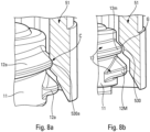
- the threads 12a extend helically, the thread pattern 530a is formed at different axial levels on the different bosses 53.
- the thread 12a in the right part forms an imprint 530a near the lower end of the boss 53, while on the left part, the imprint 530a is formed towards the top of the boss 53.
- the threads do not come into contact of the skirt 51 only at the level of the bosses 53.
- the contact between the skirt and the collar is only partial on the periphery, and preferably extends over less than half of the periphery of the collar. This is the case given that there are only twelve bosses 53 distributed around the periphery. This interrupted contact considerably reduces the friction forces between the skirt and the collar, thus allowing manual unscrewing of the dispensing head.
- the torque is applied directly to the hoop 6 which is in tight contact with the ring 5.
- the contact between the hoop and the ring extends over the entire periphery and advantageously almost over the entire height of the ring. The friction between the ring and the hoop is therefore much greater than the friction between the bosses 53 and the threads 12a. Unscrewing is then authorized.
- each imprint 530a comprises a bottom imprint 531 bordered by two opposite imprint sides 532 and 533. This means that the formation of the thread imprints 530a was made without generating traction on the tabs 52. In other words, the inward radial thrust created by the hoop 6 was not transformed into an axial thrust component during contact of the bosses 53 with the threads 12a. The compression of the neck seal 7 is thus entirely obtained and controlled by the force exerted by the assembly press.
- Such imprints 530a could be produced because the bosses extend on either side of the threads 12a. There is therefore no cam effect or force orientation transformation during the deformation of the bosses 53.
- the deformation of the bosses 53 is a plastic deformation by instantaneous and/or subsequent displacement of material, in particular by creep. . Indeed, we know that plastic materials tend to creep over time to reach a final state of deformation. In the context of the present invention, this creep phenomenon is taken advantage of given that a relatively long period of time passes between the assembly of the distributor and the unscrewing of the distribution head, when the tank is empty.
- the thread imprints 530 once the dispensing head has been unscrewed, will remain in this state to form a definitive complementary thread.
- the plastic material constituting the bosses 51 will not deform back through shape memory, given that the material has flowed over a long period.
- the document fixing device WO2009/150351 it is possible to fix a distribution head on a tank with a threaded neck without carrying out a screwing operation, while allowing the head to be unscrewed, to allow the recycling of the distributor by separating the tank from its distribution head.
- Screwing the distribution head back onto the threaded neck was not an objective of the document WO2009/150351 : it was enough that the head could be removed by unscrewing. Screwing back is a new requirement that meets sustainability objectives, since it allows the user to be able to fill the tank and put the distribution head back in place. We noticed that screwing back is not possible with the fixing member and the threaded neck of the document WO2009/150351 , because the thread imprints 530a formed by threaded collar in the skirt 51 are in “too” intimate contact with the threads 12a of the collar.
- the present invention provides an improvement or improvement to the document device WO2009/150351 aimed at allowing easy screwing, but also to facilitate unscrewing, without changing anything in the assembly process and the document fixing device WO2009/150351 .
- the modification is located only at the level of the threads 12a of the threaded neck 11: this implies that the ring of the invention is identical to that of the document WO2009/150351 , except at the thread indentations which are created by the neck thread.
- the threads 12 of the invention have a cross section which decreases in the direction of unscrewing or increases in the direction of screwing , so that the unscrewing torque decreases and the screwing torque increases.
- the threads are “finer” or “narrower” as they approach the upper annular edge 13.
- the threads 12 are “larger” or “wider” as they approach the shoulder 14. It can also be said that the threads 12 taper or become thinner from the bottom to the top, or from the shoulder 14 towards the upper annular edge 13 Their cross section decreases upwards.
- This reduction in section may be due to a reduction in their axial height and/or their radial thickness.
- This reduction can be continuous over the entire length of the threads. It can also be discontinuous and present segments or portions of thread of constant cross section. But overall, we can say that the threads 12 reduce in the direction of unscrewing or increase in the direction of screwing.
- the neck 11 comprises two threads 12 which extend substantially over a little more than half of the periphery of the neck: it can be seen that they overlap over a short distance.
- Each thread 12 defines an upper thread start 12m located near the edge 13 and a lower thread end 12M located near the shoulder 14.
- the start 12m and the end 12M can be defined as the end parts of the net 12 whose cross section increases/decreases rapidly.
- the start of the 12m net has a minimum cross section and the end of the 12M net has a maximum cross section. Between these two ends, the net 12 forms an intermediate portion 12i of increasing cross section going from the start of the net 12m towards the end of the net 12M.
- the length of the intermediate portion 12i is much greater than that of the beginning 12m or the end 12M.
- the variation in cross section is constant and progressive over the entire length of the intermediate portion 12i.
- the helical thread 12 at the junction between the lower end of the thread 12M and the intermediate portion 12i has a maximum cross section.
- the thread start 12m defines an axial height Hmin and a radial thickness Emin relative to the remainder of the neck 11 which is generally cylindrical.
- the net head 12m has a substantially trapezoidal shape, with two inclined side walls 121m and 123m and a substantially flat and cylindrical top 122m, so that the helical net 12 has a cross section of generally squat configuration.
- Hmin can be of the order of 1.2 mm
- Emin can be of the order of 0.3 mm to 0.5 mm.
- the end of the thread 12M defines an axial height Hmax and a radial thickness Emax.
- the end of the thread 12M also has a substantially trapezoidal shape, with two inclined side walls 121M and 123M and a substantially flat and cylindrical top 122M, so that the helical thread 12 also has a cross section of generally squat configuration.
- Hmax can be of the order of 1.5 mm and Emax can be 0.2 mm more than Emin, namely between 0.5 and 0.7 mm.
- the axial height can vary by at least 20% and the radial thickness can vary by at least 30% and preferably 50%.
- Pass 11 of the figure 9a includes three threads 12 which overlap a little. Each net defines a 12m net start of reduced section and a 12M net end of increased section. The variation in section of the intermediate portion 12i is constant, continuous and progressive over its entire length.
- Pass 11 of the figure 9b includes four threads 12 which overlap a little. Each net defines a 12m net start of reduced section and a 12M net end of increased section. The variation in section of the intermediate portion 12i is constant, continuous and progressive over its entire length.
- Pass 11 of the figure 9c includes three threads 12 which do not overlap. Each net defines a 12m net start of reduced section and a 12M net end of increased section. The variation in section of the intermediate portion 12i is constant, continuous and progressive up to a part of constant section 12MC whose end defines the end of the thread 12M.
- the intermediate portion 12i has, over at least part of its length, a cross section which decreases in the direction of unscrewing and increases in the direction of screwing, such that the unscrewing torque decreases and the screwing torque believes.
- the invention defining neck threads of increasing section in the direction of screwing, it is easy to screw back a dispensing head which has been previously unscrewed and which was initially mounted on the threaded neck by radial tightening to form the impressions of net.
- the invention essentially concerns the configuration of the neck threads, and consequently the reservoir, but the advantages induced by this particular configuration of the neck threads are manifested essentially at the level of the cooperation between this neck threaded and the skirt, which allows not only the initial axial assembly and disassembly by unscrewing, but above all easy and efficient reassembly by screwing back.
- the tank is the essential structural means, it is the distribution head which allows the invention to be carried out in association with the reservoir.
Landscapes
- Engineering & Computer Science (AREA)
- General Engineering & Computer Science (AREA)
- Mechanical Engineering (AREA)
- Closures For Containers (AREA)
Claims (12)
- Fluidproduktspender umfassend:- einen Fluidprodukt-Vorratsbehälter (1), der vorteilhafterweise aus Glas hergestellt ist und mit einem Hals (11) versehen ist, der außen ein Gewinde aufweist und innen eine Öffnung (10) definiert, die mit dem Inneren des Vorratsbehälters in Verbindung steht, wobei der Hals (11) wenigstens ein schraubenförmiges Gewinde (12) bildet, das einen oberen Gewindeanfang (12m), ein unteres Gewindeende (12M) und einen Zwischenabschnitt (12i) umfasst,- einen Abgabekopf (2), der auf dem Hals (11) des Vorratsbehälters (1) angebracht ist, wobei der Kopf (2) ein Abgabeelement (3) wie etwa eine Pumpe oder ein Ventil, einen Drücker (4) zur Betätigung des Abgabeelements (3) und ein Befestigungselement (5, 6) umfasst, das sowohl mit dem Gewindehals (11) des Vorratsbehälters (1) als auch mit dem Abgabeelement (3) in Eingriff steht, wobei das Befestigungselement (5, 6) Folgendes umfasst:- einen verformbaren und formbaren Mantel (51), der dazu bestimmt ist, mit dem Gewindehals (11) in Eingriff zu treten, und- eine starre Umreifung (6), die sich um den Mantel (51) herum in Eingriff befindet, um den Mantel radial gegen den Gewindehals (11) zu drücken, so dass der Mantel (51) gegen das Gewinde (12) verformt wird, um einen Gewindeabdruck (530) im Mantel zu erzeugen,dadurch gekennzeichnet, dass der Zwischenabschnitt (12i) auf wenigstens einem Teil seiner Länge einen Querschnitt aufweist, der in Aufschraubrichtung abnimmt und in Zuschraubrichtung zunimmt, so dass das Aufschraubmoment abnimmt und das Wiederzuschraubmoment zunimmt.
- Spender Nach Anspruch 1, wobei wenigstens die Hälfte der Länge des Zwischenabschnitts (12i) einen Querschnitt aufweist, der in Aufschraubrichtung abnimmt und in Zuschraubrichtung zunimmt, so dass das Aufschraubmoment abnimmt und das Wiederzuschraubmoment zunimmt.
- Spender nach Anspruch 1 oder 2, wobei das schraubenförmige Gewinde (12) im Bereich der Verbindung zwischen dem unteren Gewindeende (12M) und dem Zwischenabschnitt (12i) einen maximalen Querschnitt aufweist.
- Spender nach einem der vorhergehenden Ansprüche, wobei der Zwischenabschnitt (12i) einen unteren Abschnitt (12MC) mit konstantem maximalen Querschnitt umfasst.
- Spender nach einem der vorhergehenden Ansprüche, wobei der Zwischenabschnitt (12i) eine axiale Höhe und eine radiale Dicke aufweist, wobei wenigstens eine dieser zwei Größen in Aufschraubrichtung abnimmt und in Zuschraubrichtung zunimmt.
- Spender nach Anspruch 5, wobei die axiale Höhe um wenigstens 20 %, vorteilhafterweise zwischen 1 mm und 1,5 mm variiert.
- Spender nach Anspruch 5 oder 6, wobei die radiale Dicke um wenigstens 30 % und vorzugsweise um 50 %, vorteilhafterweise zwischen 0,4 mm und 0,6 mm variiert.
- Spender nach Anspruch 5, 6 oder 7, wobei das Verhältnis der axialen Höhe zur radialen Dicke in der Größenordnung von 2 bis 3 liegt.
- Spender nach einem der vorhergehenden Ansprüche, wobei der Hals (11) wenigstens zwei schraubenförmige Gewinde (12), vorteilhafterweise drei oder vier umfasst.
- Spender nach Anspruch 9, wobei sich die schraubenförmigen Gewinde (12) überlappen.
- Spender nach einem der vorhergehenden Ansprüche, wobei das wenigstens eine schraubenförmige Gewinde (12) zwei geneigte Seitenflanken (121m; 121M, 123m; 123M) und einen im Wesentlichen flachen und zylinderförmigen Scheitelpunkt (122m; 122M) umfasst, so dass das schraubenförmige Gewinde (12) einen Querschnitt aufweist, der allgemein gedrungen ausgebildet ist.
- Spender nach einem der vorhergehenden Ansprüche, wobei der Mantel (51) aus einem Kunststoff hergestellt ist und die schraubenförmigen Gewinde (12) aus Glas sind, wobei der Mantel (51) biegsame Laschen (52) umfasst, die durch Schlitze (54) getrennt sind, wobei jede biegsame Lasche (52) innen mit wenigstens einer Erhebung (53) versehen ist, die dazu bestimmt ist, von dem schraubenförmigen Gewinde (12) des Halses (11) verformt zu werden, wobei die Erhebungen (53) länglich sind und sich quer zum schraubenförmigen Gewinde (12) erstrecken.
Applications Claiming Priority (2)
| Application Number | Priority Date | Filing Date | Title |
|---|---|---|---|
| FR2003465A FR3108861B1 (fr) | 2020-04-07 | 2020-04-07 | Distributeur de produit fluide |
| PCT/FR2021/050594 WO2021205106A1 (fr) | 2020-04-07 | 2021-04-06 | Distributeur de produit fluide |
Publications (2)
| Publication Number | Publication Date |
|---|---|
| EP4132723A1 EP4132723A1 (de) | 2023-02-15 |
| EP4132723B1 true EP4132723B1 (de) | 2024-04-03 |
Family
ID=70918658
Family Applications (1)
| Application Number | Title | Priority Date | Filing Date |
|---|---|---|---|
| EP21723330.3A Active EP4132723B1 (de) | 2020-04-07 | 2021-04-06 | Fluidspender |
Country Status (7)
| Country | Link |
|---|---|
| US (1) | US12280386B2 (de) |
| EP (1) | EP4132723B1 (de) |
| CN (1) | CN115461157B (de) |
| BR (1) | BR112022019664A2 (de) |
| ES (1) | ES2977688T3 (de) |
| FR (1) | FR3108861B1 (de) |
| WO (1) | WO2021205106A1 (de) |
Families Citing this family (3)
| Publication number | Priority date | Publication date | Assignee | Title |
|---|---|---|---|---|
| FR3108861B1 (fr) * | 2020-04-07 | 2022-06-24 | Aptar France Sas | Distributeur de produit fluide |
| US12569867B2 (en) | 2022-11-03 | 2026-03-10 | The Clorox Company | Apparatus for use with multiple coupleable accessories |
| US20250296103A1 (en) * | 2024-03-19 | 2025-09-25 | The Clorox Company | Apparatus for use with multiple coupleable accessories |
Family Cites Families (18)
| Publication number | Priority date | Publication date | Assignee | Title |
|---|---|---|---|---|
| GB1386624A (en) * | 1972-02-10 | 1975-03-12 | Patel C S | Container with anti-pilfer closure |
| US4781311A (en) * | 1984-08-17 | 1988-11-01 | The Clorox Company | Angular positioned trigger sprayer with selective snap-screw container connection |
| AU577665B2 (en) * | 1985-02-15 | 1988-09-29 | George Seabrook Wing | Torque-limited collar and process for setting joint |
| US5169033A (en) * | 1991-11-13 | 1992-12-08 | Specialty Packaging Licensing Company, Inc. | Container-closure assembly including a screw-cap having anti-backoff teeth on its threads |
| JP3280715B2 (ja) * | 1992-08-31 | 2002-05-13 | 大治郎 中村 | 締付け用ネジ |
| FR2701010B1 (fr) * | 1993-02-04 | 1995-03-24 | Valois | Dispositif de bouchage à dévissage irréversible. |
| US5676270A (en) * | 1996-06-12 | 1997-10-14 | Aptargroup, Inc. | Threaded container torque retention system for use with a threaded closure |
| US5713479A (en) * | 1996-09-25 | 1998-02-03 | Vincent T. Brady | Molded plastic screw cap having anti-backoff thread |
| FR2802513B1 (fr) * | 1999-12-16 | 2002-02-15 | Valois Sa | Reservoir et distributeur de produit fluide a securite de devissage |
| GB2409200B (en) * | 2003-12-19 | 2007-01-17 | Beeson & Sons Ltd | Bottle and closure assembly with improved locking elements |
| MX2010009240A (es) * | 2008-03-04 | 2010-10-20 | Church & Dwight Co Inc | Combinacion de tapa y boquilla. |
| FR2931138B1 (fr) | 2008-05-19 | 2010-05-28 | Valois Sas | Distributeur de produit fluide |
| FR2952620B1 (fr) * | 2009-11-19 | 2011-12-30 | Valois Sas | Distributeur de produit fluide. |
| JP5394288B2 (ja) * | 2010-03-10 | 2014-01-22 | 株式会社ファンケル | 吐出器及び吐出器付き容器 |
| DE102011015004B4 (de) * | 2011-03-25 | 2018-06-28 | E-PROPLAST-GmbH | Außengewinde für das Halsteil von Kunststoffbehältern |
| GB2540439A (en) * | 2015-07-17 | 2017-01-18 | Alternative Packaging Solutions Llc | A pump mechanism for a spray dispenser |
| FI3388697T4 (fi) * | 2017-04-13 | 2025-11-26 | Tyco Electronics Simel | Leikkautuva kiinnityspultti ja menetelmä sähköjohtojen kiinnittämiseen sekä ulkonemattoman leikkautuvan kiinnittimen käsittävä sähköliitin |
| FR3108861B1 (fr) * | 2020-04-07 | 2022-06-24 | Aptar France Sas | Distributeur de produit fluide |
-
2020
- 2020-04-07 FR FR2003465A patent/FR3108861B1/fr not_active Expired - Fee Related
-
2021
- 2021-04-06 US US17/917,117 patent/US12280386B2/en active Active
- 2021-04-06 WO PCT/FR2021/050594 patent/WO2021205106A1/fr not_active Ceased
- 2021-04-06 CN CN202180030987.XA patent/CN115461157B/zh active Active
- 2021-04-06 ES ES21723330T patent/ES2977688T3/es active Active
- 2021-04-06 EP EP21723330.3A patent/EP4132723B1/de active Active
- 2021-04-06 BR BR112022019664A patent/BR112022019664A2/pt not_active Application Discontinuation
Also Published As
| Publication number | Publication date |
|---|---|
| WO2021205106A1 (fr) | 2021-10-14 |
| FR3108861B1 (fr) | 2022-06-24 |
| ES2977688T3 (es) | 2024-08-28 |
| CN115461157B (zh) | 2023-11-14 |
| US20230149960A1 (en) | 2023-05-18 |
| FR3108861A1 (fr) | 2021-10-08 |
| US12280386B2 (en) | 2025-04-22 |
| EP4132723A1 (de) | 2023-02-15 |
| BR112022019664A2 (pt) | 2022-11-29 |
| CN115461157A (zh) | 2022-12-09 |
Similar Documents
| Publication | Publication Date | Title |
|---|---|---|
| EP2279045B1 (de) | Flüssigproduktspender | |
| FR2952620A1 (fr) | Distributeur de produit fluide. | |
| WO2021205106A1 (fr) | Distributeur de produit fluide | |
| EP0775072B1 (de) | Flasche mit veränderlichem volumen | |
| EP2459317B1 (de) | Entfernbares befestigungssystem | |
| EP2427274B1 (de) | Anbringvorrichtung zum anbringen einer pumpe an einem tankstutzen | |
| EP2237897B1 (de) | Fluidproduktspender | |
| EP2600984B1 (de) | Fixiersystem und spender für ein flüssigkeitsprodukt mit einem derartigen system | |
| FR2584785A1 (fr) | Element de fixation borgne auto-obturant et procede pour sa mise en oeuvre | |
| WO2012140358A1 (fr) | Fond de récipient pétaloïde à double vallée | |
| FR2815610A1 (fr) | Dispositif de fixation et distributeur utilisant un tel dispositif de fixation | |
| WO2008152282A2 (fr) | Dispositif de fixation pour fixer une pompe sur un reservoir et distributeur utilisant un tel dispositif de fixation | |
| EP4142952B1 (de) | Spender für flüssige produkte | |
| EP1851072B1 (de) | Vorrichtung zur montage einer speiche an einer radfelge oder nabe | |
| EP3956068B1 (de) | Flüssigproduktspender | |
| EP2714281B1 (de) | Befestigungselement und spender mit einem solchen körper | |
| EP3756769B1 (de) | Befestigungssystem eines verteilungsorgans auf dem gewindehals eines behälters | |
| EP1957204B1 (de) | Abdeckungsglied, verfahren zur herstellung solch eines glieds und solch ein glied verwendender fluidproduktspender | |
| FR2836189A1 (fr) | Cheville d'ancrage pour une vis | |
| WO2019106315A1 (fr) | Procédé de fabrication d'une paroi de distribution | |
| FR3156762A3 (fr) | Ensemble récipient et virole avec système de distribution de fluide | |
| FR3145556A1 (fr) | Système de rétention | |
| FR3140264A1 (fr) | Bâton cosmetique |
Legal Events
| Date | Code | Title | Description |
|---|---|---|---|
| STAA | Information on the status of an ep patent application or granted ep patent |
Free format text: STATUS: UNKNOWN |
|
| STAA | Information on the status of an ep patent application or granted ep patent |
Free format text: STATUS: THE INTERNATIONAL PUBLICATION HAS BEEN MADE |
|
| PUAI | Public reference made under article 153(3) epc to a published international application that has entered the european phase |
Free format text: ORIGINAL CODE: 0009012 |
|
| STAA | Information on the status of an ep patent application or granted ep patent |
Free format text: STATUS: REQUEST FOR EXAMINATION WAS MADE |
|
| 17P | Request for examination filed |
Effective date: 20221103 |
|
| AK | Designated contracting states |
Kind code of ref document: A1 Designated state(s): AL AT BE BG CH CY CZ DE DK EE ES FI FR GB GR HR HU IE IS IT LI LT LU LV MC MK MT NL NO PL PT RO RS SE SI SK SM TR |
|
| DAV | Request for validation of the european patent (deleted) | ||
| DAX | Request for extension of the european patent (deleted) | ||
| REG | Reference to a national code |
Ref country code: DE Ref legal event code: R079 Free format text: PREVIOUS MAIN CLASS: B05B0011000000 Ipc: B05B0011100000 Ref document number: 602021011344 Country of ref document: DE |
|
| GRAP | Despatch of communication of intention to grant a patent |
Free format text: ORIGINAL CODE: EPIDOSNIGR1 |
|
| STAA | Information on the status of an ep patent application or granted ep patent |
Free format text: STATUS: GRANT OF PATENT IS INTENDED |
|
| RIC1 | Information provided on ipc code assigned before grant |
Ipc: F16B 33/00 20060101ALI20231011BHEP Ipc: F16B 29/00 20060101ALI20231011BHEP Ipc: B05B 11/10 20230101AFI20231011BHEP |
|
| INTG | Intention to grant announced |
Effective date: 20231103 |
|
| P01 | Opt-out of the competence of the unified patent court (upc) registered |
Effective date: 20240117 |
|
| GRAS | Grant fee paid |
Free format text: ORIGINAL CODE: EPIDOSNIGR3 |
|
| GRAA | (expected) grant |
Free format text: ORIGINAL CODE: 0009210 |
|
| STAA | Information on the status of an ep patent application or granted ep patent |
Free format text: STATUS: THE PATENT HAS BEEN GRANTED |
|
| AK | Designated contracting states |
Kind code of ref document: B1 Designated state(s): AL AT BE BG CH CY CZ DE DK EE ES FI FR GB GR HR HU IE IS IT LI LT LU LV MC MK MT NL NO PL PT RO RS SE SI SK SM TR |
|
| REG | Reference to a national code |
Ref country code: CH Ref legal event code: EP |
|
| REG | Reference to a national code |
Ref country code: DE Ref legal event code: R096 Ref document number: 602021011344 Country of ref document: DE |
|
| REG | Reference to a national code |
Ref country code: IE Ref legal event code: FG4D Free format text: LANGUAGE OF EP DOCUMENT: FRENCH |
|
| REG | Reference to a national code |
Ref country code: LT Ref legal event code: MG9D |
|
| REG | Reference to a national code |
Ref country code: NL Ref legal event code: MP Effective date: 20240403 |
|
| REG | Reference to a national code |
Ref country code: ES Ref legal event code: FG2A Ref document number: 2977688 Country of ref document: ES Kind code of ref document: T3 Effective date: 20240828 |
|
| REG | Reference to a national code |
Ref country code: AT Ref legal event code: MK05 Ref document number: 1671680 Country of ref document: AT Kind code of ref document: T Effective date: 20240403 |
|
| PG25 | Lapsed in a contracting state [announced via postgrant information from national office to epo] |
Ref country code: NL Free format text: LAPSE BECAUSE OF FAILURE TO SUBMIT A TRANSLATION OF THE DESCRIPTION OR TO PAY THE FEE WITHIN THE PRESCRIBED TIME-LIMIT Effective date: 20240403 |
|
| PG25 | Lapsed in a contracting state [announced via postgrant information from national office to epo] |
Ref country code: NL Free format text: LAPSE BECAUSE OF FAILURE TO SUBMIT A TRANSLATION OF THE DESCRIPTION OR TO PAY THE FEE WITHIN THE PRESCRIBED TIME-LIMIT Effective date: 20240403 |
|
| PG25 | Lapsed in a contracting state [announced via postgrant information from national office to epo] |
Ref country code: IS Free format text: LAPSE BECAUSE OF FAILURE TO SUBMIT A TRANSLATION OF THE DESCRIPTION OR TO PAY THE FEE WITHIN THE PRESCRIBED TIME-LIMIT Effective date: 20240803 |
|
| PG25 | Lapsed in a contracting state [announced via postgrant information from national office to epo] |
Ref country code: BG Free format text: LAPSE BECAUSE OF FAILURE TO SUBMIT A TRANSLATION OF THE DESCRIPTION OR TO PAY THE FEE WITHIN THE PRESCRIBED TIME-LIMIT Effective date: 20240403 |
|
| PG25 | Lapsed in a contracting state [announced via postgrant information from national office to epo] |
Ref country code: HR Free format text: LAPSE BECAUSE OF FAILURE TO SUBMIT A TRANSLATION OF THE DESCRIPTION OR TO PAY THE FEE WITHIN THE PRESCRIBED TIME-LIMIT Effective date: 20240403 Ref country code: FI Free format text: LAPSE BECAUSE OF FAILURE TO SUBMIT A TRANSLATION OF THE DESCRIPTION OR TO PAY THE FEE WITHIN THE PRESCRIBED TIME-LIMIT Effective date: 20240403 |
|
| PG25 | Lapsed in a contracting state [announced via postgrant information from national office to epo] |
Ref country code: GR Free format text: LAPSE BECAUSE OF FAILURE TO SUBMIT A TRANSLATION OF THE DESCRIPTION OR TO PAY THE FEE WITHIN THE PRESCRIBED TIME-LIMIT Effective date: 20240704 |
|
| PG25 | Lapsed in a contracting state [announced via postgrant information from national office to epo] |
Ref country code: PT Free format text: LAPSE BECAUSE OF FAILURE TO SUBMIT A TRANSLATION OF THE DESCRIPTION OR TO PAY THE FEE WITHIN THE PRESCRIBED TIME-LIMIT Effective date: 20240805 |
|
| PG25 | Lapsed in a contracting state [announced via postgrant information from national office to epo] |
Ref country code: CZ Free format text: LAPSE BECAUSE OF FAILURE TO SUBMIT A TRANSLATION OF THE DESCRIPTION OR TO PAY THE FEE WITHIN THE PRESCRIBED TIME-LIMIT Effective date: 20240403 |
|
| PG25 | Lapsed in a contracting state [announced via postgrant information from national office to epo] |
Ref country code: AT Free format text: LAPSE BECAUSE OF FAILURE TO SUBMIT A TRANSLATION OF THE DESCRIPTION OR TO PAY THE FEE WITHIN THE PRESCRIBED TIME-LIMIT Effective date: 20240403 |
|
| PG25 | Lapsed in a contracting state [announced via postgrant information from national office to epo] |
Ref country code: PL Free format text: LAPSE BECAUSE OF FAILURE TO SUBMIT A TRANSLATION OF THE DESCRIPTION OR TO PAY THE FEE WITHIN THE PRESCRIBED TIME-LIMIT Effective date: 20240403 |
|
| PG25 | Lapsed in a contracting state [announced via postgrant information from national office to epo] |
Ref country code: LV Free format text: LAPSE BECAUSE OF FAILURE TO SUBMIT A TRANSLATION OF THE DESCRIPTION OR TO PAY THE FEE WITHIN THE PRESCRIBED TIME-LIMIT Effective date: 20240403 |
|
| PG25 | Lapsed in a contracting state [announced via postgrant information from national office to epo] |
Ref country code: PT Free format text: LAPSE BECAUSE OF FAILURE TO SUBMIT A TRANSLATION OF THE DESCRIPTION OR TO PAY THE FEE WITHIN THE PRESCRIBED TIME-LIMIT Effective date: 20240805 Ref country code: PL Free format text: LAPSE BECAUSE OF FAILURE TO SUBMIT A TRANSLATION OF THE DESCRIPTION OR TO PAY THE FEE WITHIN THE PRESCRIBED TIME-LIMIT Effective date: 20240403 Ref country code: NO Free format text: LAPSE BECAUSE OF FAILURE TO SUBMIT A TRANSLATION OF THE DESCRIPTION OR TO PAY THE FEE WITHIN THE PRESCRIBED TIME-LIMIT Effective date: 20240703 Ref country code: LV Free format text: LAPSE BECAUSE OF FAILURE TO SUBMIT A TRANSLATION OF THE DESCRIPTION OR TO PAY THE FEE WITHIN THE PRESCRIBED TIME-LIMIT Effective date: 20240403 Ref country code: IS Free format text: LAPSE BECAUSE OF FAILURE TO SUBMIT A TRANSLATION OF THE DESCRIPTION OR TO PAY THE FEE WITHIN THE PRESCRIBED TIME-LIMIT Effective date: 20240803 Ref country code: HR Free format text: LAPSE BECAUSE OF FAILURE TO SUBMIT A TRANSLATION OF THE DESCRIPTION OR TO PAY THE FEE WITHIN THE PRESCRIBED TIME-LIMIT Effective date: 20240403 Ref country code: GR Free format text: LAPSE BECAUSE OF FAILURE TO SUBMIT A TRANSLATION OF THE DESCRIPTION OR TO PAY THE FEE WITHIN THE PRESCRIBED TIME-LIMIT Effective date: 20240704 Ref country code: FI Free format text: LAPSE BECAUSE OF FAILURE TO SUBMIT A TRANSLATION OF THE DESCRIPTION OR TO PAY THE FEE WITHIN THE PRESCRIBED TIME-LIMIT Effective date: 20240403 Ref country code: CZ Free format text: LAPSE BECAUSE OF FAILURE TO SUBMIT A TRANSLATION OF THE DESCRIPTION OR TO PAY THE FEE WITHIN THE PRESCRIBED TIME-LIMIT Effective date: 20240403 Ref country code: BG Free format text: LAPSE BECAUSE OF FAILURE TO SUBMIT A TRANSLATION OF THE DESCRIPTION OR TO PAY THE FEE WITHIN THE PRESCRIBED TIME-LIMIT Effective date: 20240403 Ref country code: AT Free format text: LAPSE BECAUSE OF FAILURE TO SUBMIT A TRANSLATION OF THE DESCRIPTION OR TO PAY THE FEE WITHIN THE PRESCRIBED TIME-LIMIT Effective date: 20240403 Ref country code: RS Free format text: LAPSE BECAUSE OF FAILURE TO SUBMIT A TRANSLATION OF THE DESCRIPTION OR TO PAY THE FEE WITHIN THE PRESCRIBED TIME-LIMIT Effective date: 20240703 |
|
| REG | Reference to a national code |
Ref country code: DE Ref legal event code: R119 Ref document number: 602021011344 Country of ref document: DE |
|
| REG | Reference to a national code |
Ref country code: CH Ref legal event code: PL |
|
| PG25 | Lapsed in a contracting state [announced via postgrant information from national office to epo] |
Ref country code: LU Free format text: LAPSE BECAUSE OF NON-PAYMENT OF DUE FEES Effective date: 20240406 |
|
| REG | Reference to a national code |
Ref country code: BE Ref legal event code: MM Effective date: 20240430 |
|
| PG25 | Lapsed in a contracting state [announced via postgrant information from national office to epo] |
Ref country code: LU Free format text: LAPSE BECAUSE OF NON-PAYMENT OF DUE FEES Effective date: 20240406 |
|
| PG25 | Lapsed in a contracting state [announced via postgrant information from national office to epo] |
Ref country code: DE Free format text: LAPSE BECAUSE OF NON-PAYMENT OF DUE FEES Effective date: 20241105 |
|
| PG25 | Lapsed in a contracting state [announced via postgrant information from national office to epo] |
Ref country code: DK Free format text: LAPSE BECAUSE OF FAILURE TO SUBMIT A TRANSLATION OF THE DESCRIPTION OR TO PAY THE FEE WITHIN THE PRESCRIBED TIME-LIMIT Effective date: 20240403 |
|
| PG25 | Lapsed in a contracting state [announced via postgrant information from national office to epo] |
Ref country code: BE Free format text: LAPSE BECAUSE OF NON-PAYMENT OF DUE FEES Effective date: 20240430 |
|
| PG25 | Lapsed in a contracting state [announced via postgrant information from national office to epo] |
Ref country code: EE Free format text: LAPSE BECAUSE OF FAILURE TO SUBMIT A TRANSLATION OF THE DESCRIPTION OR TO PAY THE FEE WITHIN THE PRESCRIBED TIME-LIMIT Effective date: 20240403 |
|
| PG25 | Lapsed in a contracting state [announced via postgrant information from national office to epo] |
Ref country code: SK Free format text: LAPSE BECAUSE OF FAILURE TO SUBMIT A TRANSLATION OF THE DESCRIPTION OR TO PAY THE FEE WITHIN THE PRESCRIBED TIME-LIMIT Effective date: 20240403 Ref country code: RO Free format text: LAPSE BECAUSE OF FAILURE TO SUBMIT A TRANSLATION OF THE DESCRIPTION OR TO PAY THE FEE WITHIN THE PRESCRIBED TIME-LIMIT Effective date: 20240403 |
|
| PG25 | Lapsed in a contracting state [announced via postgrant information from national office to epo] |
Ref country code: SM Free format text: LAPSE BECAUSE OF FAILURE TO SUBMIT A TRANSLATION OF THE DESCRIPTION OR TO PAY THE FEE WITHIN THE PRESCRIBED TIME-LIMIT Effective date: 20240403 |
|
| PG25 | Lapsed in a contracting state [announced via postgrant information from national office to epo] |
Ref country code: SM Free format text: LAPSE BECAUSE OF FAILURE TO SUBMIT A TRANSLATION OF THE DESCRIPTION OR TO PAY THE FEE WITHIN THE PRESCRIBED TIME-LIMIT Effective date: 20240403 Ref country code: SK Free format text: LAPSE BECAUSE OF FAILURE TO SUBMIT A TRANSLATION OF THE DESCRIPTION OR TO PAY THE FEE WITHIN THE PRESCRIBED TIME-LIMIT Effective date: 20240403 Ref country code: RO Free format text: LAPSE BECAUSE OF FAILURE TO SUBMIT A TRANSLATION OF THE DESCRIPTION OR TO PAY THE FEE WITHIN THE PRESCRIBED TIME-LIMIT Effective date: 20240403 Ref country code: EE Free format text: LAPSE BECAUSE OF FAILURE TO SUBMIT A TRANSLATION OF THE DESCRIPTION OR TO PAY THE FEE WITHIN THE PRESCRIBED TIME-LIMIT Effective date: 20240403 Ref country code: DK Free format text: LAPSE BECAUSE OF FAILURE TO SUBMIT A TRANSLATION OF THE DESCRIPTION OR TO PAY THE FEE WITHIN THE PRESCRIBED TIME-LIMIT Effective date: 20240403 Ref country code: DE Free format text: LAPSE BECAUSE OF NON-PAYMENT OF DUE FEES Effective date: 20241105 Ref country code: BE Free format text: LAPSE BECAUSE OF NON-PAYMENT OF DUE FEES Effective date: 20240430 Ref country code: CH Free format text: LAPSE BECAUSE OF NON-PAYMENT OF DUE FEES Effective date: 20240430 Ref country code: MC Free format text: LAPSE BECAUSE OF FAILURE TO SUBMIT A TRANSLATION OF THE DESCRIPTION OR TO PAY THE FEE WITHIN THE PRESCRIBED TIME-LIMIT Effective date: 20240403 |
|
| PLBE | No opposition filed within time limit |
Free format text: ORIGINAL CODE: 0009261 |
|
| STAA | Information on the status of an ep patent application or granted ep patent |
Free format text: STATUS: NO OPPOSITION FILED WITHIN TIME LIMIT |
|
| 26N | No opposition filed |
Effective date: 20250106 |
|
| PG25 | Lapsed in a contracting state [announced via postgrant information from national office to epo] |
Ref country code: IE Free format text: LAPSE BECAUSE OF NON-PAYMENT OF DUE FEES Effective date: 20240406 |
|
| PG25 | Lapsed in a contracting state [announced via postgrant information from national office to epo] |
Ref country code: SI Free format text: LAPSE BECAUSE OF FAILURE TO SUBMIT A TRANSLATION OF THE DESCRIPTION OR TO PAY THE FEE WITHIN THE PRESCRIBED TIME-LIMIT Effective date: 20240403 |
|
| PGFP | Annual fee paid to national office [announced via postgrant information from national office to epo] |
Ref country code: ES Payment date: 20250512 Year of fee payment: 5 |
|
| PGFP | Annual fee paid to national office [announced via postgrant information from national office to epo] |
Ref country code: FR Payment date: 20250428 Year of fee payment: 5 |
|
| PG25 | Lapsed in a contracting state [announced via postgrant information from national office to epo] |
Ref country code: CY Free format text: LAPSE BECAUSE OF FAILURE TO SUBMIT A TRANSLATION OF THE DESCRIPTION OR TO PAY THE FEE WITHIN THE PRESCRIBED TIME-LIMIT; INVALID AB INITIO Effective date: 20210406 |
|
| PG25 | Lapsed in a contracting state [announced via postgrant information from national office to epo] |
Ref country code: HU Free format text: LAPSE BECAUSE OF FAILURE TO SUBMIT A TRANSLATION OF THE DESCRIPTION OR TO PAY THE FEE WITHIN THE PRESCRIBED TIME-LIMIT; INVALID AB INITIO Effective date: 20210406 |
|
| PG25 | Lapsed in a contracting state [announced via postgrant information from national office to epo] |
Ref country code: SE Free format text: LAPSE BECAUSE OF FAILURE TO SUBMIT A TRANSLATION OF THE DESCRIPTION OR TO PAY THE FEE WITHIN THE PRESCRIBED TIME-LIMIT Effective date: 20240403 |
|
| PG25 | Lapsed in a contracting state [announced via postgrant information from national office to epo] |
Ref country code: TR Free format text: LAPSE BECAUSE OF FAILURE TO SUBMIT A TRANSLATION OF THE DESCRIPTION OR TO PAY THE FEE WITHIN THE PRESCRIBED TIME-LIMIT Effective date: 20240403 |
|
| GBPC | Gb: european patent ceased through non-payment of renewal fee |
Effective date: 20250406 |
|
| PG25 | Lapsed in a contracting state [announced via postgrant information from national office to epo] |
Ref country code: GB Free format text: LAPSE BECAUSE OF NON-PAYMENT OF DUE FEES Effective date: 20250406 |
|
| PG25 | Lapsed in a contracting state [announced via postgrant information from national office to epo] |
Ref country code: IT Free format text: LAPSE BECAUSE OF FAILURE TO SUBMIT A TRANSLATION OF THE DESCRIPTION OR TO PAY THE FEE WITHIN THE PRESCRIBED TIME-LIMIT Effective date: 20240403 |