EP4132750B1 - Befestigungsmechanismus - Google Patents
Befestigungsmechanismus Download PDFInfo
- Publication number
- EP4132750B1 EP4132750B1 EP21717176.8A EP21717176A EP4132750B1 EP 4132750 B1 EP4132750 B1 EP 4132750B1 EP 21717176 A EP21717176 A EP 21717176A EP 4132750 B1 EP4132750 B1 EP 4132750B1
- Authority
- EP
- European Patent Office
- Prior art keywords
- fastening mechanism
- male component
- component
- locking member
- cutaway
- Prior art date
- Legal status (The legal status is an assumption and is not a legal conclusion. Google has not performed a legal analysis and makes no representation as to the accuracy of the status listed.)
- Active
Links
Images



Classifications
-
- B—PERFORMING OPERATIONS; TRANSPORTING
- B25—HAND TOOLS; PORTABLE POWER-DRIVEN TOOLS; MANIPULATORS
- B25B—TOOLS OR BENCH DEVICES NOT OTHERWISE PROVIDED FOR, FOR FASTENING, CONNECTING, DISENGAGING, OR HOLDING
- B25B23/00—Details of, or accessories for, spanners, wrenches, screwdrivers
- B25B23/0007—Connections or joints between tool parts
-
- B—PERFORMING OPERATIONS; TRANSPORTING
- B25—HAND TOOLS; PORTABLE POWER-DRIVEN TOOLS; MANIPULATORS
- B25B—TOOLS OR BENCH DEVICES NOT OTHERWISE PROVIDED FOR, FOR FASTENING, CONNECTING, DISENGAGING, OR HOLDING
- B25B23/00—Details of, or accessories for, spanners, wrenches, screwdrivers
- B25B23/16—Handles
-
- B—PERFORMING OPERATIONS; TRANSPORTING
- B25—HAND TOOLS; PORTABLE POWER-DRIVEN TOOLS; MANIPULATORS
- B25G—HANDLES FOR HAND IMPLEMENTS
- B25G3/00—Attaching handles to the implements
- B25G3/02—Socket, tang, or like fixings
- B25G3/12—Locking and securing devices
- B25G3/16—Locking and securing devices comprising bayonet joints
Definitions
- the present invention relates to a fastening mechanism between a male and a female component, particularly, although not exclusively, the handle and head of a torque wrench.
- Torque wrenches are fundamental tools used in many industries, particularly the manufacturing and maintenance industries, to apply a predetermined amount of torque to a fastener (e.g. a nut, screw or bolt).
- a fastener e.g. a nut, screw or bolt.
- the current method of fastening a detachable end fitting to the handle of a torque wrench involves the use of a plunger-and-hole arrangement.
- This arrangement comprises a male component and a female component, which may be a spigot on the handle and an opening on the end fitting of the tool respectively (or vice versa).
- the male and female components respectively further comprise a radial plunger and a corresponding hole.
- the components are fastened together by the engagement of the spring-biased plunger within the hole when the spigot is inserted into the female component.
- a protruding push button formed by the distal end of the plunger, must be pressed to disengage the plunger from the hole, thereby allowing the male component to be withdrawn from the female component.
- the Applicant has identified that the conventional fastening mechanism is incompatible with tools that must be used in proximity to live electrical components. It is a requirement of the relevant standards that such tools are covered in an insulating material to protect the user. Therefore, the current fastening mechanism used in the art (i.e. the plunger-and-hole mechanism) is inadequate for such applications, as the insulating layer would have to be removed in order to depress the plunger, thereby substantially increasing the level of inconvenience and risk to the user.
- the current fastening mechanism used in the art i.e. the plunger-and-hole mechanism
- the present invention seeks to provide a fastening mechanism that overcomes these shortcomings.
- US 5 482 413 A discloses a pneumatic tool comprising a motor element that includes a body in which a pneumatic motor is housed.
- WO 97/47436 A1 discloses a clamping chuck that holds an auxiliary rotary tool such as a screwdriver or a cutting tool.
- US 5 407 293 A discloses a coupling apparatus for a medical instrument.
- US 2005/034573 A1 discloses a hand tool that includes a retractable shank, a handle, an elastic member, and at least one fixing pin.
- the invention When viewed from a first aspect, provides a fastening mechanism comprising a male component and a female component;
- the present invention provides a fastening mechanism comprising a male component and a female component.
- the male component is arranged to be inserted into a bore of the female component, thereby locating a locking member of the female component within a groove of the male component. This engagement prevents relative axial displacement of the male and female components.
- the locking member of the female component is further arranged to be received within a cutaway of the male component. The engagement between the locking member and the cutaway helps to prevent both the relative axial and rotational movement of the male and female components, thereby providing a more reliable connection, e.g. which may not be disconnected accidentally.
- the claimed fastening mechanism may be realised without the use of protruding parts, the present invention may be provided with a layer of insulating material without impairing its function. Therefore, the claimed fastening mechanism is suitable for use with insulated tools and indeed in a set of embodiments the male and female components both comprise an electrically insulating external layer - e.g. one at least .
- the male component comprises a handle of a tool (e.g. a torque wrench). However, in some embodiments, the male component comprises an end fitting (e.g for attaching to a handle of a tool). In some embodiments, the female component comprises a handle of a tool (e.g. a torque wrench). However, in some embodiments, the female component comprises an end fitting (e.g for attaching to a handle of a tool).
- the male component may comprise a spigot.
- the spigot may be arranged at a distal end of the male component.
- the spigot is substantially cylindrical.
- the spigot may be between 5mm and 35mm in diameter.
- the bore is cylindrical.
- the bore may extend along a central axis of the female component.
- the bore may be arranged to receive the spigot of the male component.
- the cutaway may be defined by a planar first surface having a normal parallel to the longitudinal axis of the male component and a second surface radially and axially perpendicular to the first surface.
- first surface When the locking member is brought into engagement with the cutaway, the first surface may act to limit relative axial displacement of the male and female components and the second surface may act to limit relative rotational movement. This arrangement may reduce the likelihood that the locking member accidentally slips out of engagement with the cutaway.
- the male and female components are arranged to be unfastened by moving the female component relative to the male component from the second position to the first position.
- the locking member must first be axially moved out of the cutaway. The components may be subsequently rotated relative to each other to allow axial separation.
- the spigot 4 further defines a cutaway 14 that extends from a radial edge of the flat surface 10 in a direction that is perpendicular to the plane of the flat surface 10.
- the spigot 4 further comprises a biasing member 16, e.g. a compression spring.
- a biasing member 16 e.g. a compression spring.
- an end of the biasing member 16 protrudes axially from the distal end of the spigot 4.
- the end of the biasing member 16 is flush with the distal end of the spigot 4.
- Figure 2 shows a side view of the spigot 4 shown in Figure 1 and the removable end fitting 6 prior to attachment.
- the end fitting 6 comprises a body 18 that could comprise any desired functional head for engaging with a workpiece. (not shown).
- the body 18 of the end fitting 6 further defines a cylindrical bore 20 that extends partially into the body 18. The diameter of the bore 20 is designed to accommodate the spigot 4.
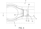
- Figure 4 shows a plan view of the fastening mechanism 2 after a subsequent stage of fastening.
- the end fitting 6 is rotated 90 degrees relative to the handle 3 such that the pin 24 is brought into engagement with the groove 12 and then rotates around it. This attaches the end fitting 6 to the spigot 4 of the handle 3 by preventing them from being axially separated.
- the bias force of the biasing member 16 pushes the end fitting 6 away from the spigot 4, thereby moving the pin 24 into engagement with the cutaway 14, as shown in Figures 5a and 5b .
- This engagement between the pin 24 and the cutaway 14 ensures that the pin 24 is locked into position and prevents both relative axial and rotational movement between the spigot 4 and the end fitting 6.
- the biasing member 16 ensures the seating of the pin 24 within the cutaway 14 to prevent accidental disengagement.
- the fastening mechanism 2 may be released by first exerting an axial force on the spigot 4, against the force of the biasing member 16, such that the pin 24 is brought out of engagement with the cutaway 14. In this way, the fastening mechanism 2 is moved to the intermediate stage shown in Figure 4 .
- the end fitting 6 can then be rotated 90 degrees relative to the spigot 4, thereby sliding the pin 24 circumferentially around the groove 12 until the pin 24 is brought into alignment with the flat surface 10, as shown in Figures 3a and 3b .
- the spigot 4 may be withdrawn from the bore 20 of the end fitting 6 to fully release the fastening mechanism 2.
Landscapes
- Engineering & Computer Science (AREA)
- Mechanical Engineering (AREA)
- Details Of Spanners, Wrenches, And Screw Drivers And Accessories (AREA)
- Snaps, Bayonet Connections, Set Pins, And Snap Rings (AREA)
Claims (15)
- Befestigungsmechanismus (2), der eine männliche Komponente (4) und eine weibliche Komponente (6) umfasst;wobei die weibliche Komponente umfassteine Bohrung (20), die angeordnet ist, um die männliche Komponente aufzunehmen; undein Verriegelungselement (24), das durch die Bohrung vorspringt;wobei die männliche Komponente definierteine Nut (12), die sich mindestens teilweise um eine Außenoberfläche der männlichen Komponente herum erstreckt und angeordnet ist, um in einer ersten Position der weiblichen Komponente in Bezug zur männlichen Komponente das Verriegelungselement aufzunehmen; undeinen Ausschnitt (14), der sich aus der Nut erstreckt und angeordnet ist, um in einer zweiten Position der weiblichen Komponente in Bezug zur männlichen Komponente das Verriegelungselement aufzunehmen.
- Befestigungsmechanismus (2) nach Anspruch 1, wobei die männliche Komponente (4) einen Griff eines Werkzeugs umfasst und die weibliche Komponente (6) ein Endstück umfasst.
- Befestigungsmechanismus (2) nach einem vorstehenden Anspruch, wobei das Verriegelungselement (24) zylindrisch ist.
- Befestigungsmechanismus (2) nach einem vorstehenden Anspruch, wobei die Nut (12) einen bogenförmigen Querschnitt umfasst.
- Befestigungsmechanismus (2) nach einem vorstehenden Anspruch, wobei die männliche Komponente (4) eine Schlüsseloberfläche (10) umfasst, die bemessen ist, um am Verriegelungselement (24) vorbeizugleiten, wenn die männliche Komponente in die Bohrung (20) eingesetzt wird.
- Befestigungsmechanismus (2) nach Anspruch 5, wobei sich die Schlüsseloberfläche (10) axial zwischen einem distalen Ende der männlichen Komponente (4) und der Nut (12) erstreckt.
- Befestigungsmechanismus (2) nach Anspruch 5 oder 6, wobei die Schlüsseloberfläche (10) flach ist.
- Befestigungsmechanismus (2) nach einem der Ansprüche 5 bis 7, wobei der Ausschnitt (14) senkrecht zur Schlüsseloberfläche (10) verläuft.
- Befestigungsmechanismus (2) nach einem vorstehenden Anspruch, wobei die männliche Komponente (4) einen Anschlag (8a) umfasst, und wobei das Verriegelungselement (24) angeordnet ist, um in der ersten Position der weiblichen Komponente (6) in Bezug zur männlichen Komponente am Anschlag anzuliegen.
- Befestigungsmechanismus (2) nach Anspruch 9, wobei die Nut (12) an den Anschlag (8a) angrenzt.
- Befestigungsmechanismus (2) nach einem vorstehenden Anspruch, wobei sich der Ausschnitt (14) aus einer Wand der Nut (12) erstreckt.
- Befestigungsmechanismus (2) nach einem vorstehenden Anspruch, wobei sich der Ausschnitt (14) bis zu mindestens der gleichen radialen Tiefe wie die Tiefe der Nut (12) erstreckt.
- Befestigungsmechanismus (2) nach einem vorstehenden Anspruch, wobei der Ausschnitt (14) eine flache erste Oberfläche, die eine Normale parallel zur Längsachse der männlichen Komponente (4) aufweist, und eine zweite Oberfläche radial und axial senkrecht zur ersten Fläche umfasst.
- Befestigungsmechanismus (2) nach einem vorstehenden Anspruch, wobei der Ausschnitt (14) einen gekrümmten Sitz für das Verriegelungselement (24) definiert.
- Befestigungsmechanismus (2) nach einem vorstehenden Anspruch, der weiter ein Vorspannelement (16) umfasst, das angeordnet ist, um das Verriegelungselement (24) in der zweiten Position in den Ausschnitt (14) vorzuspannen.
Applications Claiming Priority (2)
| Application Number | Priority Date | Filing Date | Title |
|---|---|---|---|
| GB2005081.1A GB2593898A (en) | 2020-04-06 | 2020-04-06 | Fastening Mechanism |
| PCT/GB2021/050810 WO2021205147A1 (en) | 2020-04-06 | 2021-03-31 | Fastening mechanism |
Publications (2)
| Publication Number | Publication Date |
|---|---|
| EP4132750A1 EP4132750A1 (de) | 2023-02-15 |
| EP4132750B1 true EP4132750B1 (de) | 2025-06-25 |
Family
ID=70768999
Family Applications (1)
| Application Number | Title | Priority Date | Filing Date |
|---|---|---|---|
| EP21717176.8A Active EP4132750B1 (de) | 2020-04-06 | 2021-03-31 | Befestigungsmechanismus |
Country Status (3)
| Country | Link |
|---|---|
| EP (1) | EP4132750B1 (de) |
| GB (1) | GB2593898A (de) |
| WO (1) | WO2021205147A1 (de) |
Family Cites Families (6)
| Publication number | Priority date | Publication date | Assignee | Title |
|---|---|---|---|---|
| US5407293A (en) * | 1993-04-29 | 1995-04-18 | Crainich; Lawrence | Coupling apparatus for medical instrument |
| FR2704793B1 (fr) * | 1993-05-06 | 1995-07-21 | Maire Charles Ets | Outil pneumatique. |
| WO1997047436A1 (de) * | 1996-06-13 | 1997-12-18 | Institut Straumann Ag | Spannfutter für ein einsteckbares werkzeug |
| US6959629B2 (en) * | 2003-08-15 | 2005-11-01 | Chih-Ching Hsien | Hand tool having a retractable handle structure |
| TWM308139U (en) * | 2006-06-26 | 2007-03-21 | Yi-Ting Lin | Structure of adjustable wrench |
| US20110056338A1 (en) * | 2009-09-07 | 2011-03-10 | Chih-Ching Hsieh | Contractible wrench structure |
-
2020
- 2020-04-06 GB GB2005081.1A patent/GB2593898A/en not_active Withdrawn
-
2021
- 2021-03-31 EP EP21717176.8A patent/EP4132750B1/de active Active
- 2021-03-31 WO PCT/GB2021/050810 patent/WO2021205147A1/en not_active Ceased
Also Published As
| Publication number | Publication date |
|---|---|
| GB202005081D0 (en) | 2020-05-20 |
| WO2021205147A1 (en) | 2021-10-14 |
| GB2593898A (en) | 2021-10-13 |
| EP4132750A1 (de) | 2023-02-15 |
Similar Documents
| Publication | Publication Date | Title |
|---|---|---|
| US5813296A (en) | Quick release socket mechanism | |
| US7481135B2 (en) | Hand tool with adjustable head | |
| EP2349648B1 (de) | Schnellwechseleinsatz und sechskantschlüsselhalteranordnung für ein werkzeug zur installation von befestigungsmitteln | |
| CN110023040B (zh) | 操作棒的连结结构 | |
| US9089901B2 (en) | Flexible and extendible drill bit assembly | |
| US8708312B2 (en) | Pry bar | |
| CN114055355B (zh) | 用于钳子的按钮释放机构 | |
| JP2002137111A (ja) | ホールソー及びパイロットドリルビットと共に使用するための迅速交換マンドレルアセンブリ | |
| AU2007250166B2 (en) | Coupling mechanisms for detachably engaging tool attachments | |
| US10953521B2 (en) | Driver | |
| US11173585B2 (en) | Shaft securing mechanism | |
| AU2024202714B2 (en) | Indexable trim tool | |
| US6119559A (en) | Socket wrench extension | |
| EP4132750A1 (de) | Befestigungsmechanismus | |
| EP0433284B1 (de) | Einrastvorrichtung für den antrieb eines steckschrauben-schlüssels | |
| HK40123028A (en) | Indexable trim tool | |
| JP7539157B2 (ja) | 工具用ソケット | |
| HK40061886A (en) | Push button release mechanism for pliers | |
| HK40075397A (en) | Push button release mechanism for pliers | |
| HK40020146A (en) | Push button pin for pliers | |
| HK40061886B (zh) | 用於钳子的按钮释放机构 | |
| HK1007983A1 (en) | Quick release mechanism for tools such as socket wrenches | |
| HK1127004A (en) | Tool with a coupling mechanisms for detachably engaging tool attachments | |
| HK1127004B (en) | Tool with a coupling mechanisms for detachably engaging tool attachments | |
| TWM312399U (en) | Quick-release joint for hand tool |
Legal Events
| Date | Code | Title | Description |
|---|---|---|---|
| STAA | Information on the status of an ep patent application or granted ep patent |
Free format text: STATUS: UNKNOWN |
|
| STAA | Information on the status of an ep patent application or granted ep patent |
Free format text: STATUS: THE INTERNATIONAL PUBLICATION HAS BEEN MADE |
|
| PUAI | Public reference made under article 153(3) epc to a published international application that has entered the european phase |
Free format text: ORIGINAL CODE: 0009012 |
|
| STAA | Information on the status of an ep patent application or granted ep patent |
Free format text: STATUS: REQUEST FOR EXAMINATION WAS MADE |
|
| 17P | Request for examination filed |
Effective date: 20221103 |
|
| AK | Designated contracting states |
Kind code of ref document: A1 Designated state(s): AL AT BE BG CH CY CZ DE DK EE ES FI FR GB GR HR HU IE IS IT LI LT LU LV MC MK MT NL NO PL PT RO RS SE SI SK SM TR |
|
| DAV | Request for validation of the european patent (deleted) | ||
| DAX | Request for extension of the european patent (deleted) | ||
| GRAP | Despatch of communication of intention to grant a patent |
Free format text: ORIGINAL CODE: EPIDOSNIGR1 |
|
| STAA | Information on the status of an ep patent application or granted ep patent |
Free format text: STATUS: GRANT OF PATENT IS INTENDED |
|
| INTG | Intention to grant announced |
Effective date: 20240808 |
|
| GRAJ | Information related to disapproval of communication of intention to grant by the applicant or resumption of examination proceedings by the epo deleted |
Free format text: ORIGINAL CODE: EPIDOSDIGR1 |
|
| STAA | Information on the status of an ep patent application or granted ep patent |
Free format text: STATUS: REQUEST FOR EXAMINATION WAS MADE |
|
| INTC | Intention to grant announced (deleted) | ||
| GRAP | Despatch of communication of intention to grant a patent |
Free format text: ORIGINAL CODE: EPIDOSNIGR1 |
|
| STAA | Information on the status of an ep patent application or granted ep patent |
Free format text: STATUS: GRANT OF PATENT IS INTENDED |
|
| INTG | Intention to grant announced |
Effective date: 20250117 |
|
| GRAS | Grant fee paid |
Free format text: ORIGINAL CODE: EPIDOSNIGR3 |
|
| GRAA | (expected) grant |
Free format text: ORIGINAL CODE: 0009210 |
|
| STAA | Information on the status of an ep patent application or granted ep patent |
Free format text: STATUS: THE PATENT HAS BEEN GRANTED |
|
| AK | Designated contracting states |
Kind code of ref document: B1 Designated state(s): AL AT BE BG CH CY CZ DE DK EE ES FI FR GB GR HR HU IE IS IT LI LT LU LV MC MK MT NL NO PL PT RO RS SE SI SK SM TR |
|
| P01 | Opt-out of the competence of the unified patent court (upc) registered |
Free format text: CASE NUMBER: APP_23555/2025 Effective date: 20250516 |
|
| REG | Reference to a national code |
Ref country code: GB Ref legal event code: FG4D |
|
| REG | Reference to a national code |
Ref country code: CH Ref legal event code: EP |
|
| REG | Reference to a national code |
Ref country code: CH Ref legal event code: EP |
|
| REG | Reference to a national code |
Ref country code: IE Ref legal event code: FG4D |
|
| REG | Reference to a national code |
Ref country code: DE Ref legal event code: R096 Ref document number: 602021032824 Country of ref document: DE |
|
| PG25 | Lapsed in a contracting state [announced via postgrant information from national office to epo] |
Ref country code: FI Free format text: LAPSE BECAUSE OF FAILURE TO SUBMIT A TRANSLATION OF THE DESCRIPTION OR TO PAY THE FEE WITHIN THE PRESCRIBED TIME-LIMIT Effective date: 20250625 |
|
| REG | Reference to a national code |
Ref country code: LT Ref legal event code: MG9D |
|
| PG25 | Lapsed in a contracting state [announced via postgrant information from national office to epo] |
Ref country code: NO Free format text: LAPSE BECAUSE OF FAILURE TO SUBMIT A TRANSLATION OF THE DESCRIPTION OR TO PAY THE FEE WITHIN THE PRESCRIBED TIME-LIMIT Effective date: 20250925 Ref country code: GR Free format text: LAPSE BECAUSE OF FAILURE TO SUBMIT A TRANSLATION OF THE DESCRIPTION OR TO PAY THE FEE WITHIN THE PRESCRIBED TIME-LIMIT Effective date: 20250926 |
|
| PG25 | Lapsed in a contracting state [announced via postgrant information from national office to epo] |
Ref country code: BG Free format text: LAPSE BECAUSE OF FAILURE TO SUBMIT A TRANSLATION OF THE DESCRIPTION OR TO PAY THE FEE WITHIN THE PRESCRIBED TIME-LIMIT Effective date: 20250625 |
|
| PG25 | Lapsed in a contracting state [announced via postgrant information from national office to epo] |
Ref country code: HR Free format text: LAPSE BECAUSE OF FAILURE TO SUBMIT A TRANSLATION OF THE DESCRIPTION OR TO PAY THE FEE WITHIN THE PRESCRIBED TIME-LIMIT Effective date: 20250625 |
|
| PG25 | Lapsed in a contracting state [announced via postgrant information from national office to epo] |
Ref country code: RS Free format text: LAPSE BECAUSE OF FAILURE TO SUBMIT A TRANSLATION OF THE DESCRIPTION OR TO PAY THE FEE WITHIN THE PRESCRIBED TIME-LIMIT Effective date: 20250925 |
|
| PG25 | Lapsed in a contracting state [announced via postgrant information from national office to epo] |
Ref country code: LV Free format text: LAPSE BECAUSE OF FAILURE TO SUBMIT A TRANSLATION OF THE DESCRIPTION OR TO PAY THE FEE WITHIN THE PRESCRIBED TIME-LIMIT Effective date: 20250625 |
|
| REG | Reference to a national code |
Ref country code: NL Ref legal event code: MP Effective date: 20250625 |
|
| PG25 | Lapsed in a contracting state [announced via postgrant information from national office to epo] |
Ref country code: NL Free format text: LAPSE BECAUSE OF FAILURE TO SUBMIT A TRANSLATION OF THE DESCRIPTION OR TO PAY THE FEE WITHIN THE PRESCRIBED TIME-LIMIT Effective date: 20250625 |
|
| PG25 | Lapsed in a contracting state [announced via postgrant information from national office to epo] |
Ref country code: PT Free format text: LAPSE BECAUSE OF FAILURE TO SUBMIT A TRANSLATION OF THE DESCRIPTION OR TO PAY THE FEE WITHIN THE PRESCRIBED TIME-LIMIT Effective date: 20251027 |
|
| REG | Reference to a national code |
Ref country code: AT Ref legal event code: MK05 Ref document number: 1805990 Country of ref document: AT Kind code of ref document: T Effective date: 20250625 |
|
| PG25 | Lapsed in a contracting state [announced via postgrant information from national office to epo] |
Ref country code: IS Free format text: LAPSE BECAUSE OF FAILURE TO SUBMIT A TRANSLATION OF THE DESCRIPTION OR TO PAY THE FEE WITHIN THE PRESCRIBED TIME-LIMIT Effective date: 20251025 |
|
| PG25 | Lapsed in a contracting state [announced via postgrant information from national office to epo] |
Ref country code: AT Free format text: LAPSE BECAUSE OF FAILURE TO SUBMIT A TRANSLATION OF THE DESCRIPTION OR TO PAY THE FEE WITHIN THE PRESCRIBED TIME-LIMIT Effective date: 20250625 Ref country code: SM Free format text: LAPSE BECAUSE OF FAILURE TO SUBMIT A TRANSLATION OF THE DESCRIPTION OR TO PAY THE FEE WITHIN THE PRESCRIBED TIME-LIMIT Effective date: 20250625 |
|
| PG25 | Lapsed in a contracting state [announced via postgrant information from national office to epo] |
Ref country code: CZ Free format text: LAPSE BECAUSE OF FAILURE TO SUBMIT A TRANSLATION OF THE DESCRIPTION OR TO PAY THE FEE WITHIN THE PRESCRIBED TIME-LIMIT Effective date: 20250625 |
|
| PG25 | Lapsed in a contracting state [announced via postgrant information from national office to epo] |
Ref country code: PL Free format text: LAPSE BECAUSE OF FAILURE TO SUBMIT A TRANSLATION OF THE DESCRIPTION OR TO PAY THE FEE WITHIN THE PRESCRIBED TIME-LIMIT Effective date: 20250625 |
|
| PG25 | Lapsed in a contracting state [announced via postgrant information from national office to epo] |
Ref country code: EE Free format text: LAPSE BECAUSE OF FAILURE TO SUBMIT A TRANSLATION OF THE DESCRIPTION OR TO PAY THE FEE WITHIN THE PRESCRIBED TIME-LIMIT Effective date: 20250625 |
|
| PG25 | Lapsed in a contracting state [announced via postgrant information from national office to epo] |
Ref country code: SK Free format text: LAPSE BECAUSE OF FAILURE TO SUBMIT A TRANSLATION OF THE DESCRIPTION OR TO PAY THE FEE WITHIN THE PRESCRIBED TIME-LIMIT Effective date: 20250625 |
|
| PG25 | Lapsed in a contracting state [announced via postgrant information from national office to epo] |
Ref country code: ES Free format text: LAPSE BECAUSE OF FAILURE TO SUBMIT A TRANSLATION OF THE DESCRIPTION OR TO PAY THE FEE WITHIN THE PRESCRIBED TIME-LIMIT Effective date: 20250625 |
|
| PG25 | Lapsed in a contracting state [announced via postgrant information from national office to epo] |
Ref country code: DK Free format text: LAPSE BECAUSE OF FAILURE TO SUBMIT A TRANSLATION OF THE DESCRIPTION OR TO PAY THE FEE WITHIN THE PRESCRIBED TIME-LIMIT Effective date: 20250625 |
|
| PG25 | Lapsed in a contracting state [announced via postgrant information from national office to epo] |
Ref country code: IT Free format text: LAPSE BECAUSE OF FAILURE TO SUBMIT A TRANSLATION OF THE DESCRIPTION OR TO PAY THE FEE WITHIN THE PRESCRIBED TIME-LIMIT Effective date: 20250625 |
|
| PLBE | No opposition filed within time limit |
Free format text: ORIGINAL CODE: 0009261 |
|
| STAA | Information on the status of an ep patent application or granted ep patent |
Free format text: STATUS: NO OPPOSITION FILED WITHIN TIME LIMIT |
|
| REG | Reference to a national code |
Ref country code: CH Ref legal event code: L10 Free format text: ST27 STATUS EVENT CODE: U-0-0-L10-L00 (AS PROVIDED BY THE NATIONAL OFFICE) Effective date: 20260507 |