EP4132765B1 - Verflüssiger für ein system zur generativen fertigung auf extrusionsbasis und verfahren zu dessen herstellung - Google Patents
Verflüssiger für ein system zur generativen fertigung auf extrusionsbasis und verfahren zu dessen herstellung Download PDFInfo
- Publication number
- EP4132765B1 EP4132765B1 EP21719221.0A EP21719221A EP4132765B1 EP 4132765 B1 EP4132765 B1 EP 4132765B1 EP 21719221 A EP21719221 A EP 21719221A EP 4132765 B1 EP4132765 B1 EP 4132765B1
- Authority
- EP
- European Patent Office
- Prior art keywords
- liquefier
- circular portion
- segment
- circular
- tubular body
- Prior art date
- Legal status (The legal status is an assumption and is not a legal conclusion. Google has not performed a legal analysis and makes no representation as to the accuracy of the status listed.)
- Active
Links
Images





Classifications
-
- B—PERFORMING OPERATIONS; TRANSPORTING
- B29—WORKING OF PLASTICS; WORKING OF SUBSTANCES IN A PLASTIC STATE IN GENERAL
- B29C—SHAPING OR JOINING OF PLASTICS; SHAPING OF MATERIAL IN A PLASTIC STATE, NOT OTHERWISE PROVIDED FOR; AFTER-TREATMENT OF THE SHAPED PRODUCTS, e.g. REPAIRING
- B29C48/00—Extrusion moulding, i.e. expressing the moulding material through a die or nozzle which imparts the desired form; Apparatus therefor
- B29C48/25—Component parts, details or accessories; Auxiliary operations
- B29C48/36—Means for plasticising or homogenising the moulding material or forcing it through the nozzle or die
- B29C48/50—Details of extruders
- B29C48/68—Barrels or cylinders
- B29C48/6801—Barrels or cylinders characterised by the material or their manufacturing process
-
- B—PERFORMING OPERATIONS; TRANSPORTING
- B29—WORKING OF PLASTICS; WORKING OF SUBSTANCES IN A PLASTIC STATE IN GENERAL
- B29C—SHAPING OR JOINING OF PLASTICS; SHAPING OF MATERIAL IN A PLASTIC STATE, NOT OTHERWISE PROVIDED FOR; AFTER-TREATMENT OF THE SHAPED PRODUCTS, e.g. REPAIRING
- B29C48/00—Extrusion moulding, i.e. expressing the moulding material through a die or nozzle which imparts the desired form; Apparatus therefor
- B29C48/25—Component parts, details or accessories; Auxiliary operations
- B29C48/36—Means for plasticising or homogenising the moulding material or forcing it through the nozzle or die
- B29C48/50—Details of extruders
- B29C48/68—Barrels or cylinders
- B29C48/681—Barrels or cylinders for single screws
-
- B—PERFORMING OPERATIONS; TRANSPORTING
- B29—WORKING OF PLASTICS; WORKING OF SUBSTANCES IN A PLASTIC STATE IN GENERAL
- B29C—SHAPING OR JOINING OF PLASTICS; SHAPING OF MATERIAL IN A PLASTIC STATE, NOT OTHERWISE PROVIDED FOR; AFTER-TREATMENT OF THE SHAPED PRODUCTS, e.g. REPAIRING
- B29C48/00—Extrusion moulding, i.e. expressing the moulding material through a die or nozzle which imparts the desired form; Apparatus therefor
- B29C48/25—Component parts, details or accessories; Auxiliary operations
- B29C48/36—Means for plasticising or homogenising the moulding material or forcing it through the nozzle or die
- B29C48/50—Details of extruders
- B29C48/68—Barrels or cylinders
- B29C48/685—Barrels or cylinders characterised by their inner surfaces, e.g. having grooves, projections or threads
-
- B—PERFORMING OPERATIONS; TRANSPORTING
- B29—WORKING OF PLASTICS; WORKING OF SUBSTANCES IN A PLASTIC STATE IN GENERAL
- B29C—SHAPING OR JOINING OF PLASTICS; SHAPING OF MATERIAL IN A PLASTIC STATE, NOT OTHERWISE PROVIDED FOR; AFTER-TREATMENT OF THE SHAPED PRODUCTS, e.g. REPAIRING
- B29C64/00—Additive manufacturing, i.e. manufacturing of three-dimensional [3D] objects by additive deposition, additive agglomeration or additive layering, e.g. by 3D printing, stereolithography or selective laser sintering
- B29C64/10—Processes of additive manufacturing
- B29C64/106—Processes of additive manufacturing using only liquids or viscous materials, e.g. depositing a continuous bead of viscous material
- B29C64/118—Processes of additive manufacturing using only liquids or viscous materials, e.g. depositing a continuous bead of viscous material using filamentary material being melted, e.g. fused deposition modelling [FDM]
-
- B—PERFORMING OPERATIONS; TRANSPORTING
- B29—WORKING OF PLASTICS; WORKING OF SUBSTANCES IN A PLASTIC STATE IN GENERAL
- B29C—SHAPING OR JOINING OF PLASTICS; SHAPING OF MATERIAL IN A PLASTIC STATE, NOT OTHERWISE PROVIDED FOR; AFTER-TREATMENT OF THE SHAPED PRODUCTS, e.g. REPAIRING
- B29C64/00—Additive manufacturing, i.e. manufacturing of three-dimensional [3D] objects by additive deposition, additive agglomeration or additive layering, e.g. by 3D printing, stereolithography or selective laser sintering
- B29C64/20—Apparatus for additive manufacturing; Details thereof or accessories therefor
- B29C64/205—Means for applying layers
- B29C64/209—Heads; Nozzles
-
- B—PERFORMING OPERATIONS; TRANSPORTING
- B29—WORKING OF PLASTICS; WORKING OF SUBSTANCES IN A PLASTIC STATE IN GENERAL
- B29C—SHAPING OR JOINING OF PLASTICS; SHAPING OF MATERIAL IN A PLASTIC STATE, NOT OTHERWISE PROVIDED FOR; AFTER-TREATMENT OF THE SHAPED PRODUCTS, e.g. REPAIRING
- B29C64/00—Additive manufacturing, i.e. manufacturing of three-dimensional [3D] objects by additive deposition, additive agglomeration or additive layering, e.g. by 3D printing, stereolithography or selective laser sintering
- B29C64/20—Apparatus for additive manufacturing; Details thereof or accessories therefor
- B29C64/295—Heating elements
-
- B—PERFORMING OPERATIONS; TRANSPORTING
- B33—ADDITIVE MANUFACTURING TECHNOLOGY
- B33Y—ADDITIVE MANUFACTURING, i.e. MANUFACTURING OF THREE-DIMENSIONAL [3D] OBJECTS BY ADDITIVE DEPOSITION, ADDITIVE AGGLOMERATION OR ADDITIVE LAYERING, e.g. BY 3D PRINTING, STEREOLITHOGRAPHY OR SELECTIVE LASER SINTERING
- B33Y30/00—Apparatus for additive manufacturing; Details thereof or accessories therefor
-
- B—PERFORMING OPERATIONS; TRANSPORTING
- B33—ADDITIVE MANUFACTURING TECHNOLOGY
- B33Y—ADDITIVE MANUFACTURING, i.e. MANUFACTURING OF THREE-DIMENSIONAL [3D] OBJECTS BY ADDITIVE DEPOSITION, ADDITIVE AGGLOMERATION OR ADDITIVE LAYERING, e.g. BY 3D PRINTING, STEREOLITHOGRAPHY OR SELECTIVE LASER SINTERING
- B33Y10/00—Processes of additive manufacturing
Definitions
- This invention relates generally to a liquefier for use in an extrusion-based additive manufacturing (EAM) system. More specifically, although not exclusively, this invention relates to a liquefier tube, a liquefier assembly, an extrusion head and a method of manufacturing a liquefier tube for use in an EAM system .
- EAM extrusion-based additive manufacturing
- the feedstock normally takes the form of a continuous filament of thermoplastic material.
- the filament is fed from a spool and advanced through a movable extrusion head containing a liquefier assembly.
- the liquefier assembly is configured to melt the filament such that it can be extruded through a nozzle and deposited on a print bed.
- the liquefier assembly includes a liquefier section, which can be in the form of a tube, along which the filament is advanced, and a heater or heater cartridge external of the liquefier tube.
- the heater heats the liquefier section and, by virtue of thermal transfer, the filament.
- the temperature of the filament is raised above its melting point, causing it to liquify and allowing the material to be extruded from the nozzle.
- Extrusion pressure is applied by virtue of the continual advancement of the filament upstream of the nozzle.
- both the filament and the channel or passage within or extending along the liquefier section are of substantially circular cross-section. It has been observed that because of the low thermal conductivity of thermoplastic material, heat from the heater is not efficiently and quickly transferred to the centre of a circular filament. This, in turn, can have a negative impact on both the rate and quality of extrusion.
- EP2905118 describes an extrusion nozzle with a circular inlet opening, a non-circular taper downstream of the inlet opening and an outlet opening downstream of the non-circular taper.
- US5005731 describes a hand-held extruder with a flattened dispensing nozzle.
- a first aspect of the invention provides a liquefier according to claim 1.
- Another aspect of the invention provides a liquefier assembly according to claim 12.
- Another aspect of the invention provides an additive manufacturing system according to claim 13.
- the method may comprise providing a tubular body having a substantially constant wall thickness.
- the method may comprise providing, e.g. forming, attaching or connecting, an extrusion tip at the other end of the tubular body, e.g. opposite the inlet portion, to form an outlet for dispensing material in a molten state.
- Providing an extrusion tip may comprise forming, attaching or connecting the extrusion tip to the other end of the tubular body, e.g. opposite the inlet portion.
- the extrusion tip may form or describe an outlet, e.g. for dispensing material in a molten state.
- the method may comprise deforming or crushing the tubular body at a location spaced from one of its ends, such that the tubular body transitions from the substantially circular inlet portion to the non-circular portion downstream of the inlet.
- the method may comprise deforming the tubular body by hydroforming.
- Deforming the tubular body by hydroforming may comprise placing the tubular body, or a portion thereof, in a forming tool or between a pair of dies.
- Deforming the tubular body by hydroforming may comprise injecting fluid under pressure into a passageway described by the tubular body so as to deform the tubular body, or a portion thereof, e.g. such that it conforms to a profile described by the forming tool or pair of dies.
- Another method of manufacturing a liquefier or liquefier tube comprises deforming a first sheet of material to form a first part of a liquefier or liquefier tube, deforming a second sheet of material to form a second part of a liquefier or liquefier tube, and attaching the first part to the second part to form a tubular body of the liquefier or liquefier tube.
- the first sheet and/or the second sheet may be or comprise metal, for example stainless steel.
- the first sheet and/or the second sheet may be or comprise brass, copper, tungsten, titanium, molybdenum, beryllium copper or any other suitable metal or alloy.
- the first part may be attached to the second part by welding or brazing.
- the liquefier may comprise a tube, or a hollow or tubular body, which may have a substantially circular cross-section.
- the outlet may comprise an extrusion tip, e.g. for dispensing material in a molten state.
- the method may comprise forming, attaching or connecting the extrusion tip or nozzle, e.g. removably, to the liquefier, liquefier tube or body.
- the method may comprise brazing or welding the extrusion tip or nozzle to the liquefier, liquefier tube or body, e.g. the other end of the body.
- the non-circular portion of the liquefier or body may comprise a deformed or crushed portion.
- deforming or crushing the liquefier or body or providing the non-circular portion comprises deforming or crushing the liquefier or body in a first region, e.g. to provide a first segment or section, and deforming or crushing the liquefier or body in a second region, e.g. to provide a second segment or section.
- the non-circular portion may comprise the first segment or section and/or second segment or section.
- the liquefier or body may be deformed, e.g. by crushing, a first region to provide a first segment of the non-circular portion.
- the liquefier or body may be deformed, e.g. by crushing, a second region, downstream of the first region, to provide a second segment of the non-circular portion downstream of the first segment.
- the first segment and/or second segment may be non-circular.
- deforming or crushing the liquefier or body comprises compressing the liquefier or body.
- Deforming or crushing the liquefier or body may comprise compressing the liquefier or body in a first region, e.g. to provide a first segment or section, and compressing the liquefier or body in a second region, e.g. to provide a second segment or section.
- the method may comprise compressing, deforming or crushing the liquefier or body to a first extent in a first region, and/or compressing, deforming or crushing the liquefier or body to a second extent, e.g. greater than the first extent, in a second region, e.g. so as to provide a tapered profile.
- the second region or second segment or section may be downstream of the first region or first segment or section.
- the non-circular portion of the liquefier or body may extend along a portion of the length, e.g. along a longitudinal axis or principal axis, of the liquefier, liquefier tube or body.
- the non-circular portion of the liquefier or body may comprise a tapered cross-sectional profile.
- the flow area of the passageway of the non-circular portion of the liquefier or body may comprise a tapered profile.
- the non-circular portion may taper along a portion of the length, e.g. along a longitudinal axis or principal axis, of the liquefier or body.
- the non-circular portion may have a major dimension and a minor dimension.
- the minor dimension may taper, e.g. along a portion of the length of the non-circular portion.
- the minor dimension may decrease, e.g. along a portion of the length of the non-circular portion.
- Providing a taper is advantageous in that as the filament is advanced along the liquefier or liquefier tube, the molten portion (located adjacent the wall of the tubular body) is moved toward the centre of the flow path or passageway. Further, the distance the heat has to travel to reach the centre of the passageway or flow path is decreased.
- the non-circular portion of the liquefier or body may comprise a plurality of segments or sections.
- Each of the plurality of segments or sections may comprise a deformed or crushed segment of the liquefier or body.
- Each of the plurality of segments or sections may be arranged, e.g. in series, along the length of, or principal axis of, the liquefier, liquefier tube or body.
- Each of the plurality of segments or sections may be arranged along a longitudinal axis of the liquefier, liquefier tube or body.
- Each of the plurality of segments or sections, hereinafter segments, may have a different cross-sectional shape, configuration or cross-sectional profile, e.g. from one another.
- One, e.g. a first, of the plurality of segments may have a different cross-sectional shape, configuration or cross-sectional profile from another, e.g. a second, of the plurality of segments.
- the flow area of the passageway of or in the plurality of segments may have a different cross-sectional shape, configuration or cross-sectional profile, e.g. from one another.
- the flow area of the passageway of or in one, e.g. a first, of the plurality of segments may have a different cross-sectional shape, configuration or cross-sectional profile from the passageway of or in another, e.g. a second, of the plurality of segments.
- the first segment may be deformed so as to have a minor dimension which is greater than a minor dimension of the deformed second segment.
- the method may comprise compressing the liquefier or body to a first extent or magnitude in a first region to provide the first segment,
- the method may comprise compressing the liquefier or body to a second extent or magnitude in a second region to provide the second segment.
- the second extent or magnitude may be different from, e.g. greater or less than, the first extent or magnitude.
- first segment and the second segment are rotationally offset or skewed from one another.
- the first segment and the second segment may be skewed or twisted from, or relative to, one another.
- the first segment and second segment may comprise a skew angle described therebetween.
- the first segment may comprise a portion of the liquefier or body deformed or crushed in a direction that is skewed or rotationally offset relative to a direction in which the second segment is deformed or crushed.
- first segment and second segment may be rotationally offset or skewed from one another.
- the liquefier or body may be deformed such that a minor and/or major dimension of the first segment and a corresponding minor and/or major dimension of the second segment are rotationally offset from one another.
- Providing rotational offset, or skew helps improve the thermal transmission characteristics of the liquefier, liquefier tube or body by creating a tortuous flow path for the molten material. Such a flow path promotes mixing of the melted or molten material as it is advanced along the liquefier, liquefier tube or body, allowing for more even thermal distribution through the material.
- the method may comprise compressing, deforming or crushing the liquefier or body in the first region in a first direction and compressing, deforming or crushing the liquefier or body in the second region in a second direction, the second direction being skewed or rotationally offset relative to the first direction.
- the cross-section, e.g. the cross-sectional shape, of first segment (or the passageway thereof or therein) and/or second segment (or the passageway thereof or therein) may comprise an axis of symmetry.
- An axis of symmetry of the first segment (or the passageway thereof or therein), e.g. the cross-sectional shape thereof, and a corresponding axis of symmetry of the second segment (or the passageway thereof or therein), e.g. the cross-sectional shape thereof, may be rotationally offset or skewed from one another.
- the liquefier or body comprises a substantially circular portion intermediate two or more segments.
- the liquefier or body may comprise a substantially circular portion intermediate the first segment and the second segment.
- the liquefier or body may be deformed so as to comprise a substantially circular portion intermediate the first segment and second segment.
- the non-circular cross-section of the non-circular portion (or the passageway thereof or therein), or the liquefier or body may be deformed such that, one or more segments thereof, may be substantially stadium shaped, disco-rectangular or obround.
- the non-circular cross-section of the non-circular portion, or one or more segments thereof, (or the passageway thereof or therein) may be oval, elliptical, regular polygonal, irregular polygonal, simple convex polygonal or simple concave polygonal.
- the non-circular cross-section of the non-circular portion, or one or more segments thereof, (or the passageway thereof or therein) may be star-shaped.
- the transition or change from the substantially circular portion to the non-circular portion, or one or more segments thereof, may comprise a staged, discretised and/or stepped transition.
- the first segment (or the passageway thereof or therein) may have a different cross-sectional shape, configuration or cross-sectional profile from the second segment (or the passageway thereof or therein).
- the non-circular portion may comprise a first non-circular portion and a second non-circular portion.
- the first non-circular portion and/or second non-circular portion may comprise a plurality of segments or sections. Each of the plurality of segments or sections may comprise a deformed or crushed segment of the liquefier or body.
- Each of the plurality of segments or sections may be arranged, e.g. in series, along the length of, or principal axis of, the liquefier, liquefier tube or body and/or first and/or second non-circular portion.
- Each of the plurality of segments or sections may be arranged along a longitudinal axis of the liquefier, liquefier tube or body.
- the first non-circular portion and/or second non-circular portion may be rotationally offset, twisted or skewed from one another.
- the respective segments or sections of the first non-circular portion and/or second non-circular portion e.g. their major and/or minor dimensions, may be rotationally offset or skewed from one another.
- the liquefier or body may comprise a thin-walled tube.
- the liquefier or body or thin-walled tube may comprise a, or be formed of, a thermally conductive material.
- the substantially circular portions (or the passageway thereof or therein) and the non-circular portions, or segments thereof may all have substantially equal cross-sectional areas.
- the non-circular portion, or one or more segments thereof, (or the passageway thereof or therein) may have a substantially constant cross-sectional area.
- the passageway of or in the non-circular portion, or one or more segments thereof, may have a substantially constant flow area.
- the liquefier or body may be deformed such that the passageway of or in the substantially circular portion and the non-circular portion have substantially equal flow areas.
- the liquefier or body and/or passageway may have or comprise a constant or substantially constant hydraulic diameter.
- the non-circular portion, first non-circular portion and/or second non-circular portion may have or comprise a constant or substantially constant hydraulic diameter.
- D H is the hydraulic diameter
- A is the flow area
- P is the perimeter described by the tubular body.
- the change in cross-sectional shape in the non-circular portion, first non-circular portion and/or second non-circular portion allows for more effective heat transfer to a filament material as is being advanced, but whilst without increasing the required applied pressure to generate a given flow rate.
- the liquefier or body may be made or formed of or comprise metal.
- the liquefier or body may be made of or comprise stainless steel.
- the liquefier or body may be made of or comprise brass, copper, tungsten, titanium, molybdenum, beryllium copper or any other suitable metal or alloy.
- the liquefier or body may be made of or comprise a polymeric material, e.g. a thermally conductive polymeric material.
- a polymeric material e.g. a thermally conductive polymeric material.
- Such polymeric material preferably has a melting point and/or glass transition temperature substantially higher than the filament material to melted.
- the liquefier, liquefier tube or body may comprise a heating zone.
- the heating zone may be configured to be heated, in use.
- the heating zone and non-circular portion may coincide or overlap.
- the heating zone may encompass or span the non-circular portion.
- a liquefier assembly for use in an extrusion-based additive manufacturing system, the liquefier assembly comprising a liquefier or liquefier tube as described above, and a heating means, e.g. a heater, heating element, heater element or heater cartridge, for heating a filament of material advanced, in use, into and/or along the liquefier or liquefier tube.
- a heating means e.g. a heater, heating element, heater element or heater cartridge
- the heating means may comprise a heating block or heater block.
- the heating block or heater block may comprise a heating element or heating cartridge.
- the heating means may at least partially surround the liquefier or liquefier tube and/or may surround or lie adjacent a heating zone of the liquefier or liquefier tube.
- the heating element or heating cartridge may extend along the length of the heating block or heater block.
- an extrusion head or extruder comprising a liquefier or liquefier tube as described above, or a liquefier assembly as described above.
- the extrusion head or extruder may comprise a feeder or feeding mechanism.
- the feeder or feeding mechanism may be located upstream of the liquefier, liquefier tube or liquefier assembly.
- the feeder or feeding mechanism may be configured to advance a filament of material, in use, into and/or along the liquefier or liquefier tube.
- the feeder or feeding mechanism may comprise one or more rotatable members or gears, which may be configured to contact, in use, a surface of a filament being fed or advanced into the liquefier, liquefier tube or liquefier assembly.
- the feeder or feeding mechanism may comprise a pair, e.g. of opposed, rotatable members or gears, which may be configured to contact, in use, a surface of a filament being fed or advanced into the liquefier, liquefier tube or liquefier assembly.
- the feeder or feeding mechanism or one or more rotatable members may comprise a feed roller.
- the feeder or feeding mechanism or one or more rotatable members may comprise a pair of feed rollers.
- Another aspect of the invention provides a computer program element comprising and/or describing and/or defining a three-dimensional design for use with a simulation means or a three-dimensional additive or subtractive manufacturing means or device, e.g. a three-dimensional printer or CNC machine, the three-dimensional design comprising an embodiment of the liquefier, liquefier tube, liquefier assembly, extrusion head and/or additive manufacturing system described above.
- a yet further aspect of the invention provides the computer program element embodied on a computer readable medium.
- a yet further aspect of the invention provides a control means or control system or controller comprising the aforementioned computer program element or computer readable medium.
- any controller(s), control units and/or control modules described herein may each comprise a control unit or computational device having one or more electronic processors.
- the controller may comprise a single control unit or electronic controller or alternatively different functions of the control of the system or apparatus may be embodied in, or hosted in, different control units or controllers or control modules.
- control unit and “controller” will be understood to include both a single control unit or controller and a plurality of control units or controllers collectively operating to provide the required control functionality.
- the set of instructions described herein may be embedded in a computer-readable storage medium (e.g., a non-transitory storage medium) that may comprise any mechanism for storing information in a form readable by a machine or electronic processors/computational device, including, without limitation: a magnetic storage medium (e.g., floppy diskette); optical storage medium (e.g., CD-ROM); magneto optical storage medium; read only memory (ROM); random access memory (RAM); erasable programmable memory (e.g., EPROM ad EEPROM); flash memory; or electrical or other types of medium for storing such information/instructions.
- a computer-readable storage medium e.g., a non-transitory storage medium
- a magnetic storage medium e.g., floppy diskette
- optical storage medium e.g., CD-ROM
- magneto optical storage medium e.g., magneto optical storage medium
- ROM read only memory
- RAM random access memory
- FIG. 1 there is shown a schematic of a extrusion-based additive manufacturing system 1 including a print bed 2, a gantry 3 located above the print bed 2 and an extrusion head 4 carried by, and movable along, the gantry 3.
- the gantry 3 is in the form of a guide rail system configured to allow movement of the extrusion head 4 in a horizontal plane within a boundary described by the print bed 2.
- the gantry 3 is supported above the print bed 2 by a structural frame F.
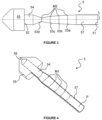
- the second end 52 is provided with an extrusion tip 55 in the form of a nozzle for dispensing filament material (not shown) in a molten state.
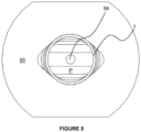
- the extrusion tip 55 provides an outlet of the liquefier tube 5 and has a substantially circular passage 56 (shown in Figure 5 , in particular) extending therealong.
- the extrusion tip 55 is welded to the tubular body 50 at the second end 52 in this example. As shown most clearly in Figure 5 , the circular passage 56 of the extrusion tip 55 is of a smaller cross-sectional area than that of the tubular body 50.
- deforming or crushing the tubular body 50 is carried out by compressing the tubular body 50 at discrete points along its length using a press.
- An extrusion tip 55 is connected to the tubular body 50 at the other end 52, opposite the inlet portion 51, to form an outlet for dispensing filament material in a molten state.
- the extrusion tip 55 is welded to the tubular body 50 in the present example.
- a liquefier tube 105 according to another example of the invention, for use in the manufacturing system 1 of Figure 1 .
- the liquefier tube 105 according to this example is similar to liquefier tube 5 according to the first example, wherein like features will be denoted by like references incremented by '100'.
- the liquefier tube 105 includes a tubular body 150 providing a passageway P extending therealong and having sidewall of substantially constant wall thickness t (as shown in Figure 9 , in particular) that extends along a longitudinal axis L.
- the tubular body 150 is formed of metal, in particular stainless steel, in this example.
- a first, upstream end of the liquefier tube 105 is provided with an inlet portion 151 of substantially circular cross-section.
- a second, downstream end 152 of the liquefier tube 105, opposite the inlet portion 151, is also provided with a substantially circular cross-section.
- the inlet portion 151 and second end 152 are located at opposite ends of the tubular body 150.
- first non-circular portion 153 having a non-circular cross-section, in the form of an obround cross-section in this example.
- the first non-circular portion 153 is similar to non-circular portion 53 of liquefier tube 5, and extends uninterrupted along a portion of the length of the tubular body 150, and has a substantially constant cross-sectional area.
- a first end portion 157, having a substantially circular cross-section extends along a portion of the length of the tubular body 150 between the inlet portion 151 and first non-circular portion 153.
- the first non-circular portion 153 has four discrete segments: a first segment 153a, second segment 153b downstream of first segment 153a, third segment 153c downstream of second segment 153b and fourth segment 153d downstream of third segment 153c.
- Each of the segments 153a:153d are arranged in series along the longitudinal axis L of the first non-circular portion 153.
- a second non-circular portion 158 Downstream of the first non-circular portion 153, between the first non-circular portion 153 and the second end 152 is a second non-circular portion 158.
- the second non-circular portion 158 is similar to the first non-circular portion 153, but rotationally offset by 90 degrees.
- the second non-circular portion 158 is similar to non-circular portion 53 of liquefier tube 5, and extends uninterrupted along a portion of the length of the tubular body 150, and has a substantially constant cross-sectional area.
- a second end portion 154, having a substantially circular cross-section extends along a portion of the length of the tubular body 150 between the second end 152 and second non-circular portion 158.
- the second non-circular portion 158 has four discrete segments: a first segment 158a, second segment 158b downstream of first segment 158a, third segment 158c downstream of second segment 158b and fourth segment 158d downstream of third segment 158c.
- Each of the segments 158a:158d are arranged in series along the longitudinal axis L of the second non-circular portion 158.
- first non-circular portion 153 and second non-circular portion 158 is a transition point or zone T at which the orientation of the non-circular part of the liquefier tube 105 is rotated by 90 degrees.
- the tubular body 150 is deformed by crushing to provide the first non-circular portion 153 and second non-circular portion 158.
- each segment 153a:153d and 158a:158d corresponds to a crush point/zone at which the tubular body 150 is deformed.
- a substantially continuous transition is provided between each segment 153a:153d and 158a:158d and between the first non-circular portion 153 and second non-circular portion 158 via the transition point or zone T.
- the tubular body 150 includes a continual transition when viewed downstream from the substantially circular cross section of the inlet portion 151 to the non-circular cross section of the first segment 153a.
- the cross sectional area at the inlet portion 51 is substantially equal to the cross sectional area of the first segment 153a in this example.
- Each of the segments 153a:153d and 158a:158d has a major dimension M1 and a minor dimension M2.
- major dimension M1 increases whilst the minor dimension M2 decreases.
- the major dimension M1 reaches its maximum and the minor dimension M2 reaches its minimum at the fourth segment 153d.
- second non-circular portion 158 when viewed from the transition point or zone T toward the second end 152.
- the minor dimension M2 is less than the diameter of the inlet portion 151 and second end 152. Therefore, the minimum distance from the sidewall of the tubular body 150 to the centre of the passageway P is reduced in the first non-circular portion 153 and second non-circular portion 158 when compared to the substantially circular cross-section of the inlet portion 151 and second end 152.
- the second non-circular portion 158 transitions from a non-circular cross section to the second end portion 154 having a substantially circular cross section at the downstream end 152.
- the second end portion 154 extends along a portion of the length of the tubular body 150 between the second non-circular portion 158 and downstream end 152.
- the length of the perimeter described by the tubular body 150 in the first non-circular portion 153 and second non-circular portion 158 is greater than that at the first end portion 157 and second end portion 154. This provides a greater contact area between the tubular body 150 and filament (not shown), increasing the rate of heat transfer.
- Heating means H in the form of one or more heating element(s) in this example, is located within the extrusion head 4 and adjacent the liquefier tube 105.
- the one or more heating element(s) are configured to heat an external surface of the liquefier tube 105, which by virtue of thermal transfer, in turn heats the filament material as it is advanced.
- the filament material As the filament material is advanced from the inlet portion 151 toward the first non-circular portion 153, it becomes molten as a result of the heating.
- the cross-sectional shape of the filament material then conforms to the cross-sectional shape of the first non-circular portion 153.
- the distance from the heating means H to the centre of the passageway P, and therefore centre of the filament material, or filament flow-path is reduced, allowing heat to more effectively reach the centre of the filament material. This allows for more effective heat transfer.
- the filament is then advanced from the first non-circular portion 153 toward the second non-circular portion 158, via the transition point or zone T.
- the rotational offset of the first non-circular portion 153 and second non-circular portion 158 results in mixing of the filament material, improving the heat transfer therethrough.
- Extrusion pressure is created by the feeding of filament upstream.
- the molten filament is extruded from the extrusion tip 155 and onto the print bed 2 (as shown in Figure 1 , in particular).
- the liquefier tube 105 of Figures 6 to 9 is manufactured by providing a tubular body 150 having a substantially constant wall thickness t and substantially circular cross-section.
- the tubular body 150 is deformed or crushed in a first direction at locations defined by segments 153a:153d, so as to provide an inlet portion 151 and first end portion 157 having a substantially circular cross-section for receiving a filament of material (not shown), and a first non-circular portion 153, formed of segments 153a:153d, each having a non-circular cross-section.
- a substantially continuous transition is provided between each segment 153a:153d.
- the tubular body 150 Downstream of the first non-circular segment 153, the tubular body 150 is deformed or crushed in a second direction, offset by 90 degrees from the first direction.
- the tubular body 150 is deformed or crushed in the second direction at locations defined by segments 158a:158d so as to provide transition point or zone T, and second end portion 152 having a substantially circular cross-section.
- deforming or crushing the tubular body 150 is carried out by compressing the tubular body 150 at discrete points along its length using a press.
- An extrusion tip 155 is connected to the tubular body 150 at the other end 152, opposite the inlet portion 151, to form an outlet for dispensing material in a molten state.
- the extrusion tip 155 is welded to the tubular body 150 in the present example.
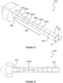
- FIG. 10 there is shown a liquefier tube 205 according to another example of the invention, for use in the manufacturing system 1 of Figure 1 .
- the liquefier tube 205 has a similar profile to liquefier tube 105, but, instead of the passageway P being described by a tubular body 150 it is described in part by a split heater block 7.
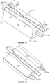
- the split heater block 7 has two halves 7a, 7b (as shown in Figure 10 , in particular). Each half 7a, 7b describes one half of the passageway P of liquefier tube 205.
- the halves 7a, 7b are configured to be secured together to form the split heater block 7 and liquefier tube 205.
- the halves 7a, 7b are configured to be secured together using screws (not shown) and are each formed of metal in this example.
- first non-circular portion 253, transition point or zone T and second non-circular portion 258 form a first element A of the liquefier tube 205 and are described by the halves 7a, 7b.
- the inlet portion 251 and first end portion 257 form a second element B of the liquefier tube 205, separate from the first element A.
- the second end 252, second end portion 254 and extrusion tip 255 form a third element C, separate from the first element A and second element B.
- the second element B is secured to a threaded aperture described in first end 70 of the split heater block 7 by virtue of a threaded connection (not shown).
- the third element C is secured to a threaded aperture described in the second end 71 of the split heater block 7 by virtue of a threaded connection (not shown).
- the first half 7a includes a cylindrical heater cartridge 71a including electrical wires 72a extending therefrom.
- the second half 7b includes a temperature sensor 71b including electrical wires 72b extending therefrom.
- Each of the cylindrical heater cartridge 71a and temperature sensor 71b are located adjacent the first element A and extend along the entire length of the heater block 7 from the first end 70 to the second end 71 (as shown in Figure 12 , in particular).
- the temperature sensor 71b and heater cartridge 71a together with a controller (not shown) allow for closed-loop feedback control of temperature via respective electrical wires 72a, 72b.
- the heater cartridge 71a is configured to provide heat around the entire circumference of the liquefier tube 205, in particular first element A, by virtue of conduction through the metal material of the halves 7a, 7b.
- each of the halves 7a, 7b are secured together using screws (not shown), in this example.
- the two halves 7a, 7b describe the first element A.
- the second element B is screwed into the threaded aperture described in the first end 70 and the third element C is screwed into the threaded aperture described in the second end 71.
- liquefier tube 205 is configured to be received within an extrusion head 4 of an extrusion-based additive manufacturing system 1 (as shown in Figure 1 , in particular).
- the substantially circular cross-section of the inlet portion 251 is configured to receive, in use, a filament of material having a circular cross section from a feeding mechanism 6.
- the filament of material is advanced along the tubular body 250.
- Heating means H in the form of the cylindrical heater cartridge 71a transfers heat to the filament through the material of the first half 7a.
- the heater cartridge 71a heats the filament material as it is advanced along the entire length of the heater block 7. Temperature output of the heater cartridge 71a is controlled via the closed-loop feedback controller discussed above.
Landscapes
- Engineering & Computer Science (AREA)
- Chemical & Material Sciences (AREA)
- Materials Engineering (AREA)
- Manufacturing & Machinery (AREA)
- Mechanical Engineering (AREA)
- Physics & Mathematics (AREA)
- Optics & Photonics (AREA)
- Extrusion Moulding Of Plastics Or The Like (AREA)
Claims (15)
- Verflüssiger (5, 105, 205, 305, 405) zur Verwendung in einem System (1) zur generativen Fertigung auf Extrusionsbasis, wobei der Verflüssiger einen Durchgang (P) beschreibt, der einen Einlassabschnitt (51, 151, 251, 351, 451) mit einem im Wesentlichen kreisförmigen Querschnitt zur Aufnahme eines Materialfilaments und einen Auslass (56, 156, 256, 356, 456) stromabwärts des Einlassabschnitts aufweist, wobei der Durchgang von dem Einlassabschnitt zu einem nicht kreisförmigen Abschnitt (53, 153, 253, 353, 453) stromabwärts des Einlassabschnitts übergeht und der nicht kreisförmige Abschnitt oder ein Segment davon sich zu einem im Wesentlichen kreisförmigen Abschnitt (54, 154, 254, 354, 454) an oder hin zu dem Auslass ausbreitet oder aufweitet, wobei der nicht kreisförmige Abschnitt einen nicht kreisförmigen Querschnitt aufweist.
- Verflüssiger nach Anspruch 1, wobei der nicht kreisförmige Querschnitt des nicht kreisförmigen Abschnitts oder eines oder mehrerer Segmente davon sternförmig ist.
- Verflüssiger nach Anspruch 1 oder Anspruch 2, wobei der Übergang von dem im Wesentlichen kreisförmigen Abschnitt zu dem nicht kreisförmigen Abschnitt oder einem oder mehreren Segmenten davon einen kontinuierlichen Übergang, allmählichen Übergang und/oder sich verjüngenden Übergang umfasst.
- Verflüssiger nach Anspruch 1 oder Anspruch 2, wobei der Übergang von dem im Wesentlichen kreisförmigen Abschnitt zu dem nicht kreisförmigen Abschnitt oder einem oder mehreren Segmenten davon einen gestuften, diskretisierten und/oder treppenförmigen Übergang umfasst.
- Verflüssiger nach einem vorhergehenden Anspruch, wobei der nicht kreisförmige Abschnitt eine Hauptabmessung (M1) und eine Nebenabmessung (M2) umfasst und die Nebenabmessung entlang eines Abschnitts der Länge des nicht kreisförmigen Abschnitts abnimmt und sich hin zu dem Auslass ausbreitet oder aufweitet.
- Verflüssiger nach einem vorhergehenden Anspruch, wobei der Einlassabschnitt, der im Wesentlichen kreisförmige Abschnitt und der nicht kreisförmige Abschnitt des Durchgangs oder Segmente davon alle im Wesentlichen gleiche Querschnittsflächen aufweisen.
- Verflüssiger nach einem vorhergehenden Anspruch, wobei der nicht kreisförmige Abschnitt eine Vielzahl von Segmenten (53a, 53b, 53c, 53d, 153, 158) umfasst, von der jedes eine andere Querschnittsform oder -konfiguration aufweist.
- Verflüssiger nach Anspruch 7, wobei der Durchgang einen im Wesentlichen kreisförmigen Abschnitt zwischen einem ersten Segment und einem zweiten Segment umfasst.
- Verflüssiger nach einem vorhergehenden Anspruch, umfassend einen rohrförmigen Körper (50, 150, 350, 450), der eine im Wesentlichen konstante Wanddicke (t) aufweist.
- Verflüssiger nach einem vorhergehenden Anspruch, wobei der Auslass eine Extrusionsspitze (55, 155, 255, 355, 455) zum Abgeben von Material in einem geschmolzenen Zustand umfasst.
- Verflüssiger nach einem vorhergehenden Anspruch, wobei der Verflüssiger aus Metall ist.
- Verflüssigerbaugruppe zur Verwendung in einem System zur generativen Fertigung auf Extrusionsbasis, wobei die Verflüssigerbaugruppe einen Verflüssiger (5, 105, 205, 305, 405) nach einem vorhergehenden Anspruch und ein Heizelement (H) zum Erhitzen eines in Verwendung innerhalb des Verflüssigers aufgenommenen Materialfilaments umfasst.
- System (1) zur generativen Fertigung, umfassend einen Verflüssiger (5, 105, 205, 305, 405) nach einem der Ansprüche 1 bis 11 oder eine Verflüssigerbaugruppe nach Anspruch 12.
- Verfahren zur Herstellung eines Verflüssigerrohrs (50, 150, 350, 450) nach einem der Ansprüche 1 bis 10 zur Verwendung in einem System zur generativen Fertigung auf Extrusionsbasis, wobei das Verfahren Bereitstellen eines rohrförmigen Körpers, der eine im Wesentlichen konstante Wanddicke und einen im Wesentlichen kreisförmigen Querschnitt aufweist, Verformen oder Zerdrücken des rohrförmigen Körpers an einer von einem seiner Enden beabstandeten Stelle, um einen Einlassabschnitt, der einen im Wesentlichen kreisförmigen Querschnitt aufweist, zum Aufnehmen eines Materialfilaments, einen nicht kreisförmigen Abschnitt, der einen nicht kreisförmigen Querschnitt aufweist, stromabwärts des Einlasses und einen im Wesentlichen kreisförmigen Abschnitt stromabwärts des nicht kreisförmigen Abschnitts bereitzustellen, umfasst.
- Verfahren zur Herstellung eines Verflüssigers nach einem der Ansprüche 1 bis 10 zur Verwendung in einem System zur generativen Fertigung auf Extrusionsbasis, wobei das Verfahren Bereitstellen eines ersten Materialblocks (7a), Bearbeiten eines ersten Teils eines Verflüssigerrohrs zu einer Oberfläche des ersten Blocks, Bereitstellen eines zweiten Materialblocks (7b), Bearbeiten eines zweiten Teils eines Verflüssigerrohrs zu einer Oberfläche des zweiten Blocks und Zusammenbringen des ersten Blocks und des zweiten Blocks, um einen Durchgang des Verflüssigerrohrs zu beschreiben, umfasst.
Priority Applications (1)
| Application Number | Priority Date | Filing Date | Title |
|---|---|---|---|
| EP25179903.7A EP4585391A3 (de) | 2020-04-08 | 2021-04-08 | Verflüssiger für ein system zur generativen fertigung auf extrusionsbasis und verfahren zu dessen herstellung |
Applications Claiming Priority (2)
| Application Number | Priority Date | Filing Date | Title |
|---|---|---|---|
| GBGB2005193.4A GB202005193D0 (en) | 2020-04-08 | 2020-04-08 | Liquefier |
| PCT/GB2021/050864 WO2021205174A1 (en) | 2020-04-08 | 2021-04-08 | Liquefier for an extrusion-based additive manufacturing system and method for its manufacturing |
Related Child Applications (2)
| Application Number | Title | Priority Date | Filing Date |
|---|---|---|---|
| EP25179903.7A Division EP4585391A3 (de) | 2020-04-08 | 2021-04-08 | Verflüssiger für ein system zur generativen fertigung auf extrusionsbasis und verfahren zu dessen herstellung |
| EP25179903.7A Division-Into EP4585391A3 (de) | 2020-04-08 | 2021-04-08 | Verflüssiger für ein system zur generativen fertigung auf extrusionsbasis und verfahren zu dessen herstellung |
Publications (3)
| Publication Number | Publication Date |
|---|---|
| EP4132765A1 EP4132765A1 (de) | 2023-02-15 |
| EP4132765C0 EP4132765C0 (de) | 2025-07-09 |
| EP4132765B1 true EP4132765B1 (de) | 2025-07-09 |
Family
ID=70768733
Family Applications (2)
| Application Number | Title | Priority Date | Filing Date |
|---|---|---|---|
| EP21719221.0A Active EP4132765B1 (de) | 2020-04-08 | 2021-04-08 | Verflüssiger für ein system zur generativen fertigung auf extrusionsbasis und verfahren zu dessen herstellung |
| EP25179903.7A Pending EP4585391A3 (de) | 2020-04-08 | 2021-04-08 | Verflüssiger für ein system zur generativen fertigung auf extrusionsbasis und verfahren zu dessen herstellung |
Family Applications After (1)
| Application Number | Title | Priority Date | Filing Date |
|---|---|---|---|
| EP25179903.7A Pending EP4585391A3 (de) | 2020-04-08 | 2021-04-08 | Verflüssiger für ein system zur generativen fertigung auf extrusionsbasis und verfahren zu dessen herstellung |
Country Status (5)
| Country | Link |
|---|---|
| US (1) | US20230150196A1 (de) |
| EP (2) | EP4132765B1 (de) |
| CN (1) | CN115697674B (de) |
| GB (1) | GB202005193D0 (de) |
| WO (1) | WO2021205174A1 (de) |
Families Citing this family (3)
| Publication number | Priority date | Publication date | Assignee | Title |
|---|---|---|---|---|
| GB202204825D0 (en) | 2021-05-19 | 2022-05-18 | E3D Online Ltd | Nozzle |
| US20240367377A1 (en) * | 2021-08-03 | 2024-11-07 | Katholieke Universiteit Leuven | Liquefier assembly for extrusion-based additive manufacturing |
| AT527166A1 (de) * | 2023-04-18 | 2024-11-15 | Plasmics Gmbh | Extrusionskopf für die additive Fertigung eines Formkörpers |
Citations (1)
| Publication number | Priority date | Publication date | Assignee | Title |
|---|---|---|---|---|
| EP2905118B1 (de) * | 2014-02-07 | 2020-06-17 | The Boeing Company | Extrusionsvorrichtung und -verfahren |
Family Cites Families (9)
| Publication number | Priority date | Publication date | Assignee | Title |
|---|---|---|---|---|
| BE551763A (de) * | 1961-05-15 | 1900-01-01 | ||
| US5005731A (en) * | 1989-06-08 | 1991-04-09 | Hardman Incorporated | Hand-held extruder |
| US6054077A (en) * | 1999-01-11 | 2000-04-25 | Stratasys, Inc. | Velocity profiling in an extrusion apparatus |
| AU2003245392A1 (en) * | 2002-06-04 | 2003-12-19 | Laird Technologies, Inc. | Manufacturing method for form-in-place gaskets having complex cross sections |
| ITMI20072229A1 (it) * | 2007-11-23 | 2009-05-24 | Ferioli Filippo S P A | Metodo e gruppo di deumidificazione di materiale plastico |
| US10259160B2 (en) * | 2013-03-22 | 2019-04-16 | Markforged, Inc. | Wear resistance in 3D printing of composites |
| US9186848B2 (en) * | 2013-03-22 | 2015-11-17 | Markforged, Inc. | Three dimensional printing of composite reinforced structures |
| US20210154916A1 (en) * | 2019-11-26 | 2021-05-27 | University Of Massachusetts | Nozzles, hot ends, and methods of their use |
| DE102021207614A1 (de) * | 2021-07-16 | 2023-01-19 | Coperion Gmbh | Verfahren und Wiederaufbereitungsanlage zur Wiederaufbereitung von Kunststoff-Abfallmaterial, insbesondere von PET-Abfallmaterial |
-
2020
- 2020-04-08 GB GBGB2005193.4A patent/GB202005193D0/en not_active Ceased
-
2021
- 2021-04-08 EP EP21719221.0A patent/EP4132765B1/de active Active
- 2021-04-08 US US17/917,408 patent/US20230150196A1/en active Pending
- 2021-04-08 EP EP25179903.7A patent/EP4585391A3/de active Pending
- 2021-04-08 CN CN202180041069.7A patent/CN115697674B/zh active Active
- 2021-04-08 WO PCT/GB2021/050864 patent/WO2021205174A1/en not_active Ceased
Patent Citations (1)
| Publication number | Priority date | Publication date | Assignee | Title |
|---|---|---|---|---|
| EP2905118B1 (de) * | 2014-02-07 | 2020-06-17 | The Boeing Company | Extrusionsvorrichtung und -verfahren |
Also Published As
| Publication number | Publication date |
|---|---|
| EP4585391A2 (de) | 2025-07-16 |
| US20230150196A1 (en) | 2023-05-18 |
| CN115697674B (zh) | 2025-12-23 |
| EP4132765A1 (de) | 2023-02-15 |
| CN115697674A (zh) | 2023-02-03 |
| EP4585391A3 (de) | 2025-10-29 |
| WO2021205174A1 (en) | 2021-10-14 |
| GB202005193D0 (en) | 2020-05-20 |
| EP4132765C0 (de) | 2025-07-09 |
Similar Documents
| Publication | Publication Date | Title |
|---|---|---|
| EP4132765B1 (de) | Verflüssiger für ein system zur generativen fertigung auf extrusionsbasis und verfahren zu dessen herstellung | |
| EP3484650B1 (de) | Verfahren zur festlegung von schweissparametern für einen schweissprozess | |
| EP3621753B1 (de) | Verfahren zur herstellung gekrümmter längen von extrudierten profilen/abschnitten in metalllegierungen | |
| EP0572105B1 (de) | Verfahren und Vorrichtung zum Herstellen einer rohrförmigen Zahnstange | |
| US5870921A (en) | Extrusion die for semi-hollow and hollow extruded shapes and tube | |
| EP2667984B1 (de) | Automatisierung rohrformpresse mit einer lichtquelle zur messung der rohrinnenkontur | |
| AT516371B1 (de) | Einrichtung zum Biegen eines Profil-Werkstücks | |
| EP3785816B1 (de) | Vorrichtung zur herstellung eines geprägten edelstahlrohrs und diese verwendendes verfahren zur herstellung eines geprägten edelstahlrohrs | |
| DE19641144A1 (de) | Verfahren und Vorrichtung zur Herstellung von Rohren | |
| WO2019057499A1 (de) | Vorrichtung zum herstellen und befüllen von behältern | |
| DE2252084B2 (de) | Verfahren zur herstellung von thermoplastischen folien | |
| JP7420026B2 (ja) | 模様付製品成形用押出しダイス | |
| US20230294169A1 (en) | Bending die and method for manufacturing bending die | |
| JP6571994B2 (ja) | コイルばね製造装置と、コイルばねの製造方法 | |
| EP0934816B1 (de) | Verfahren und Vorrichtung zur Herstellung eines kontinuierlichen Folienschlauchs aus einer ebenen Folienbahn | |
| EP3666493B1 (de) | Kühlsystem für einen formkern eines spritzgiesswerkzeuges | |
| DE102004002539A1 (de) | Biegeverfahren und -vorrichtung für thermoformbare Kunst- und Verbundstoffe | |
| WO2015024644A1 (de) | Formwerkzeug und umformvorrichtung mit formwerkzeug sowie verfahren zum herstellen und biegen von hohlprofilen | |
| EP2129507B1 (de) | Blaskopf und verfahren für die herstellung einer mehrschichtigen blasfolie | |
| EP1880780B1 (de) | Verfahren und Vorrichtung zum Strangpressen einer Bolzenvorform | |
| CN114309405B (zh) | 一种不锈钢嵌件的温镦工艺及系统 | |
| CN117980084A (zh) | 用于挤出宽幅型材的设备和方法 | |
| EP3112125A1 (de) | Extrusionssystem und verfahren zur erzeugung vielseitigerer extrudate | |
| JPH11226635A (ja) | 断面多角形閉状態の管の製造方法及びそのための装置 | |
| CN120984855A (zh) | 一种铸造三维空间变曲面铸件用电渣熔铸系统 |
Legal Events
| Date | Code | Title | Description |
|---|---|---|---|
| STAA | Information on the status of an ep patent application or granted ep patent |
Free format text: STATUS: UNKNOWN |
|
| STAA | Information on the status of an ep patent application or granted ep patent |
Free format text: STATUS: THE INTERNATIONAL PUBLICATION HAS BEEN MADE |
|
| PUAI | Public reference made under article 153(3) epc to a published international application that has entered the european phase |
Free format text: ORIGINAL CODE: 0009012 |
|
| STAA | Information on the status of an ep patent application or granted ep patent |
Free format text: STATUS: REQUEST FOR EXAMINATION WAS MADE |
|
| 17P | Request for examination filed |
Effective date: 20221101 |
|
| AK | Designated contracting states |
Kind code of ref document: A1 Designated state(s): AL AT BE BG CH CY CZ DE DK EE ES FI FR GB GR HR HU IE IS IT LI LT LU LV MC MK MT NL NO PL PT RO RS SE SI SK SM TR |
|
| DAV | Request for validation of the european patent (deleted) | ||
| DAX | Request for extension of the european patent (deleted) | ||
| GRAP | Despatch of communication of intention to grant a patent |
Free format text: ORIGINAL CODE: EPIDOSNIGR1 |
|
| STAA | Information on the status of an ep patent application or granted ep patent |
Free format text: STATUS: GRANT OF PATENT IS INTENDED |
|
| RIN1 | Information on inventor provided before grant (corrected) |
Inventor name: VAN DER KREEK, JON Inventor name: MORTIMER, SANJAY |
|
| GRAS | Grant fee paid |
Free format text: ORIGINAL CODE: EPIDOSNIGR3 |
|
| INTG | Intention to grant announced |
Effective date: 20250502 |
|
| GRAA | (expected) grant |
Free format text: ORIGINAL CODE: 0009210 |
|
| STAA | Information on the status of an ep patent application or granted ep patent |
Free format text: STATUS: THE PATENT HAS BEEN GRANTED |
|
| AK | Designated contracting states |
Kind code of ref document: B1 Designated state(s): AL AT BE BG CH CY CZ DE DK EE ES FI FR GB GR HR HU IE IS IT LI LT LU LV MC MK MT NL NO PL PT RO RS SE SI SK SM TR |
|
| REG | Reference to a national code |
Ref country code: GB Ref legal event code: FG4D |
|
| REG | Reference to a national code |
Ref country code: CH Ref legal event code: EP |
|
| REG | Reference to a national code |
Ref country code: IE Ref legal event code: FG4D |
|
| REG | Reference to a national code |
Ref country code: DE Ref legal event code: R096 Ref document number: 602021033755 Country of ref document: DE |
|
| U01 | Request for unitary effect filed |
Effective date: 20250808 |
|
| U07 | Unitary effect registered |
Designated state(s): AT BE BG DE DK EE FI FR IT LT LU LV MT NL PT RO SE SI Effective date: 20250909 |
|
| PG25 | Lapsed in a contracting state [announced via postgrant information from national office to epo] |
Ref country code: IS Free format text: LAPSE BECAUSE OF FAILURE TO SUBMIT A TRANSLATION OF THE DESCRIPTION OR TO PAY THE FEE WITHIN THE PRESCRIBED TIME-LIMIT Effective date: 20251109 |
|
| PG25 | Lapsed in a contracting state [announced via postgrant information from national office to epo] |
Ref country code: NO Free format text: LAPSE BECAUSE OF FAILURE TO SUBMIT A TRANSLATION OF THE DESCRIPTION OR TO PAY THE FEE WITHIN THE PRESCRIBED TIME-LIMIT Effective date: 20251009 |
|
| PG25 | Lapsed in a contracting state [announced via postgrant information from national office to epo] |
Ref country code: HR Free format text: LAPSE BECAUSE OF FAILURE TO SUBMIT A TRANSLATION OF THE DESCRIPTION OR TO PAY THE FEE WITHIN THE PRESCRIBED TIME-LIMIT Effective date: 20250709 |
|
| PG25 | Lapsed in a contracting state [announced via postgrant information from national office to epo] |
Ref country code: GR Free format text: LAPSE BECAUSE OF FAILURE TO SUBMIT A TRANSLATION OF THE DESCRIPTION OR TO PAY THE FEE WITHIN THE PRESCRIBED TIME-LIMIT Effective date: 20251010 |
|
| PG25 | Lapsed in a contracting state [announced via postgrant information from national office to epo] |
Ref country code: PL Free format text: LAPSE BECAUSE OF FAILURE TO SUBMIT A TRANSLATION OF THE DESCRIPTION OR TO PAY THE FEE WITHIN THE PRESCRIBED TIME-LIMIT Effective date: 20250709 |
|
| PG25 | Lapsed in a contracting state [announced via postgrant information from national office to epo] |
Ref country code: RS Free format text: LAPSE BECAUSE OF FAILURE TO SUBMIT A TRANSLATION OF THE DESCRIPTION OR TO PAY THE FEE WITHIN THE PRESCRIBED TIME-LIMIT Effective date: 20251009 |
|
| PG25 | Lapsed in a contracting state [announced via postgrant information from national office to epo] |
Ref country code: ES Free format text: LAPSE BECAUSE OF FAILURE TO SUBMIT A TRANSLATION OF THE DESCRIPTION OR TO PAY THE FEE WITHIN THE PRESCRIBED TIME-LIMIT Effective date: 20250709 |
|
| PG25 | Lapsed in a contracting state [announced via postgrant information from national office to epo] |
Ref country code: SM Free format text: LAPSE BECAUSE OF FAILURE TO SUBMIT A TRANSLATION OF THE DESCRIPTION OR TO PAY THE FEE WITHIN THE PRESCRIBED TIME-LIMIT Effective date: 20250709 |
|
| PGFP | Annual fee paid to national office [announced via postgrant information from national office to epo] |
Ref country code: GB Payment date: 20260330 Year of fee payment: 6 |
|
| PG25 | Lapsed in a contracting state [announced via postgrant information from national office to epo] |
Ref country code: CZ Free format text: LAPSE BECAUSE OF FAILURE TO SUBMIT A TRANSLATION OF THE DESCRIPTION OR TO PAY THE FEE WITHIN THE PRESCRIBED TIME-LIMIT Effective date: 20250709 |
|
| PG25 | Lapsed in a contracting state [announced via postgrant information from national office to epo] |
Ref country code: SK Free format text: LAPSE BECAUSE OF FAILURE TO SUBMIT A TRANSLATION OF THE DESCRIPTION OR TO PAY THE FEE WITHIN THE PRESCRIBED TIME-LIMIT Effective date: 20250709 |
|
| U20 | Renewal fee for the european patent with unitary effect paid |
Year of fee payment: 6 Effective date: 20260319 |