EP4132776B1 - Stratifié principal, pale d'éolienne comprenant un tel stratifié principal et procédés de fabrications. - Google Patents
Stratifié principal, pale d'éolienne comprenant un tel stratifié principal et procédés de fabrications. Download PDFInfo
- Publication number
- EP4132776B1 EP4132776B1 EP20722221.7A EP20722221A EP4132776B1 EP 4132776 B1 EP4132776 B1 EP 4132776B1 EP 20722221 A EP20722221 A EP 20722221A EP 4132776 B1 EP4132776 B1 EP 4132776B1
- Authority
- EP
- European Patent Office
- Prior art keywords
- pultrusion
- wind turbine
- fibre
- turbine blade
- main laminate
- Prior art date
- Legal status (The legal status is an assumption and is not a legal conclusion. Google has not performed a legal analysis and makes no representation as to the accuracy of the status listed.)
- Active
Links
Images




Classifications
-
- B—PERFORMING OPERATIONS; TRANSPORTING
- B29—WORKING OF PLASTICS; WORKING OF SUBSTANCES IN A PLASTIC STATE IN GENERAL
- B29C—SHAPING OR JOINING OF PLASTICS; SHAPING OF MATERIAL IN A PLASTIC STATE, NOT OTHERWISE PROVIDED FOR; AFTER-TREATMENT OF THE SHAPED PRODUCTS, e.g. REPAIRING
- B29C70/00—Shaping composites, i.e. plastics material comprising reinforcements, fillers or preformed parts, e.g. inserts
- B29C70/04—Shaping composites, i.e. plastics material comprising reinforcements, fillers or preformed parts, e.g. inserts comprising reinforcements only, e.g. self-reinforcing plastics
- B29C70/28—Shaping operations therefor
- B29C70/40—Shaping or impregnating by compression not applied
- B29C70/50—Shaping or impregnating by compression not applied for producing articles of indefinite length, e.g. prepregs, sheet moulding compounds [SMC] or cross moulding compounds [XMC]
- B29C70/52—Pultrusion, i.e. forming and compressing by continuously pulling through a die
-
- B—PERFORMING OPERATIONS; TRANSPORTING
- B29—WORKING OF PLASTICS; WORKING OF SUBSTANCES IN A PLASTIC STATE IN GENERAL
- B29C—SHAPING OR JOINING OF PLASTICS; SHAPING OF MATERIAL IN A PLASTIC STATE, NOT OTHERWISE PROVIDED FOR; AFTER-TREATMENT OF THE SHAPED PRODUCTS, e.g. REPAIRING
- B29C70/00—Shaping composites, i.e. plastics material comprising reinforcements, fillers or preformed parts, e.g. inserts
- B29C70/04—Shaping composites, i.e. plastics material comprising reinforcements, fillers or preformed parts, e.g. inserts comprising reinforcements only, e.g. self-reinforcing plastics
- B29C70/28—Shaping operations therefor
- B29C70/40—Shaping or impregnating by compression not applied
- B29C70/42—Shaping or impregnating by compression not applied for producing articles of definite length, i.e. discrete articles
-
- B—PERFORMING OPERATIONS; TRANSPORTING
- B29—WORKING OF PLASTICS; WORKING OF SUBSTANCES IN A PLASTIC STATE IN GENERAL
- B29D—PRODUCING PARTICULAR ARTICLES FROM PLASTICS OR FROM SUBSTANCES IN A PLASTIC STATE
- B29D99/00—Subject matter not provided for in other groups of this subclass
- B29D99/0025—Producing blades or the like, e.g. blades for turbines, propellers, or wings
- B29D99/0028—Producing blades or the like, e.g. blades for turbines, propellers, or wings hollow blades
-
- F—MECHANICAL ENGINEERING; LIGHTING; HEATING; WEAPONS; BLASTING
- F03—MACHINES OR ENGINES FOR LIQUIDS; WIND, SPRING, OR WEIGHT MOTORS; PRODUCING MECHANICAL POWER OR A REACTIVE PROPULSIVE THRUST, NOT OTHERWISE PROVIDED FOR
- F03D—WIND MOTORS
- F03D1/00—Wind motors with rotation axis substantially parallel to the air flow entering the rotor
- F03D1/06—Rotors
- F03D1/0608—Rotors characterised by their aerodynamic shape
- F03D1/0633—Rotors characterised by their aerodynamic shape of the blades
-
- F—MECHANICAL ENGINEERING; LIGHTING; HEATING; WEAPONS; BLASTING
- F03—MACHINES OR ENGINES FOR LIQUIDS; WIND, SPRING, OR WEIGHT MOTORS; PRODUCING MECHANICAL POWER OR A REACTIVE PROPULSIVE THRUST, NOT OTHERWISE PROVIDED FOR
- F03D—WIND MOTORS
- F03D1/00—Wind motors with rotation axis substantially parallel to the air flow entering the rotor
- F03D1/06—Rotors
- F03D1/065—Rotors characterised by their construction elements
- F03D1/0658—Arrangements for fixing wind-engaging parts to a hub
-
- F—MECHANICAL ENGINEERING; LIGHTING; HEATING; WEAPONS; BLASTING
- F03—MACHINES OR ENGINES FOR LIQUIDS; WIND, SPRING, OR WEIGHT MOTORS; PRODUCING MECHANICAL POWER OR A REACTIVE PROPULSIVE THRUST, NOT OTHERWISE PROVIDED FOR
- F03D—WIND MOTORS
- F03D1/00—Wind motors with rotation axis substantially parallel to the air flow entering the rotor
- F03D1/06—Rotors
- F03D1/065—Rotors characterised by their construction elements
- F03D1/0675—Rotors characterised by their construction elements of the blades
-
- F—MECHANICAL ENGINEERING; LIGHTING; HEATING; WEAPONS; BLASTING
- F03—MACHINES OR ENGINES FOR LIQUIDS; WIND, SPRING, OR WEIGHT MOTORS; PRODUCING MECHANICAL POWER OR A REACTIVE PROPULSIVE THRUST, NOT OTHERWISE PROVIDED FOR
- F03D—WIND MOTORS
- F03D1/00—Wind motors with rotation axis substantially parallel to the air flow entering the rotor
- F03D1/06—Rotors
- F03D1/065—Rotors characterised by their construction elements
- F03D1/0675—Rotors characterised by their construction elements of the blades
- F03D1/0679—Load carrying structures, e.g. beams
-
- B—PERFORMING OPERATIONS; TRANSPORTING
- B29—WORKING OF PLASTICS; WORKING OF SUBSTANCES IN A PLASTIC STATE IN GENERAL
- B29K—INDEXING SCHEME ASSOCIATED WITH SUBCLASSES B29B, B29C OR B29D, RELATING TO MOULDING MATERIALS OR TO MATERIALS FOR MOULDS, REINFORCEMENTS, FILLERS OR PREFORMED PARTS, e.g. INSERTS
- B29K2307/00—Use of elements other than metals as reinforcement
- B29K2307/04—Carbon
-
- B—PERFORMING OPERATIONS; TRANSPORTING
- B29—WORKING OF PLASTICS; WORKING OF SUBSTANCES IN A PLASTIC STATE IN GENERAL
- B29K—INDEXING SCHEME ASSOCIATED WITH SUBCLASSES B29B, B29C OR B29D, RELATING TO MOULDING MATERIALS OR TO MATERIALS FOR MOULDS, REINFORCEMENTS, FILLERS OR PREFORMED PARTS, e.g. INSERTS
- B29K2309/00—Use of inorganic materials not provided for in groups B29K2303/00 - B29K2307/00, as reinforcement
- B29K2309/08—Glass
-
- B—PERFORMING OPERATIONS; TRANSPORTING
- B29—WORKING OF PLASTICS; WORKING OF SUBSTANCES IN A PLASTIC STATE IN GENERAL
- B29L—INDEXING SCHEME ASSOCIATED WITH SUBCLASS B29C, RELATING TO PARTICULAR ARTICLES
- B29L2031/00—Other particular articles
- B29L2031/08—Blades for rotors, stators, fans, turbines or the like, e.g. screw propellers
- B29L2031/082—Blades, e.g. for helicopters
- B29L2031/085—Wind turbine blades
-
- F—MECHANICAL ENGINEERING; LIGHTING; HEATING; WEAPONS; BLASTING
- F05—INDEXING SCHEMES RELATING TO ENGINES OR PUMPS IN VARIOUS SUBCLASSES OF CLASSES F01-F04
- F05B—INDEXING SCHEME RELATING TO WIND, SPRING, WEIGHT, INERTIA OR LIKE MOTORS, TO MACHINES OR ENGINES FOR LIQUIDS COVERED BY SUBCLASSES F03B, F03D AND F03G
- F05B2280/00—Materials; Properties thereof
- F05B2280/60—Properties or characteristics given to material by treatment or manufacturing
- F05B2280/6003—Composites; e.g. fibre-reinforced
-
- Y—GENERAL TAGGING OF NEW TECHNOLOGICAL DEVELOPMENTS; GENERAL TAGGING OF CROSS-SECTIONAL TECHNOLOGIES SPANNING OVER SEVERAL SECTIONS OF THE IPC; TECHNICAL SUBJECTS COVERED BY FORMER USPC CROSS-REFERENCE ART COLLECTIONS [XRACs] AND DIGESTS
- Y02—TECHNOLOGIES OR APPLICATIONS FOR MITIGATION OR ADAPTATION AGAINST CLIMATE CHANGE
- Y02E—REDUCTION OF GREENHOUSE GAS [GHG] EMISSIONS, RELATED TO ENERGY GENERATION, TRANSMISSION OR DISTRIBUTION
- Y02E10/00—Energy generation through renewable energy sources
- Y02E10/70—Wind energy
- Y02E10/72—Wind turbines with rotation axis in wind direction
-
- Y—GENERAL TAGGING OF NEW TECHNOLOGICAL DEVELOPMENTS; GENERAL TAGGING OF CROSS-SECTIONAL TECHNOLOGIES SPANNING OVER SEVERAL SECTIONS OF THE IPC; TECHNICAL SUBJECTS COVERED BY FORMER USPC CROSS-REFERENCE ART COLLECTIONS [XRACs] AND DIGESTS
- Y02—TECHNOLOGIES OR APPLICATIONS FOR MITIGATION OR ADAPTATION AGAINST CLIMATE CHANGE
- Y02P—CLIMATE CHANGE MITIGATION TECHNOLOGIES IN THE PRODUCTION OR PROCESSING OF GOODS
- Y02P70/00—Climate change mitigation technologies in the production process for final industrial or consumer products
- Y02P70/50—Manufacturing or production processes characterised by the final manufactured product
Definitions
- the present disclosure relates to a main laminate for a wind turbine blade and a method of manufacturing such a main laminate.
- Wind turbine blades of fibre-reinforced polymer and in particular the aerodynamic shells of wind turbine blades are usually manufactured in moulds, where the pressure side and the suction side of the blade are manufactured separately by arranging glass fibre mats and/or other fibre-reinforcement material, such as carbon fibre, in each of the two moulds. Afterwards, one of the two halves is turned upside down and positioned on top of the other of the two halves, and the two halves are adhered together. The blade parts may be positioned on top of each other by turning and repositioning the complete half mould.
- a wind turbine blade and/or components of the wind turbine blade may be manufactured by infusing fibres, such as glass fibre mats and/or carbon fibre mats with a resin, such as polyester or epoxy. Infusion of the fibres may be provided by vacuum assisted resin transfer moulding (VARTM).
- VARTM vacuum assisted resin transfer moulding
- Components of the blade have different function, e.g. a main laminate or spar cap provides the load carrying capability of the blade and the shell or skin provides the outer aerodynamic shape of the blade.
- main laminates typically prefabricated, pultrusion elements which are reliable in strength and weight.
- blade loads i.e. strains, bending moments, peel loads etc.
- difficulty in manufacturing increase.
- blades are sometimes divided into two or more segments connected via a joint which requires space to adequately transfer loads between the segments.
- EP 2 778 393 A2 relates to a spar including an inboard portion made of first planks connected, via a butt joint, to an outboard portion made of second planks.
- a first aspect of this disclosure relates to a main laminate forming a load carrying structure for a wind turbine blade, the main laminate extending in a spanwise direction from a proximal end through a transition region to a distal end, wherein the main laminate comprises:
- Pultrusion elements have the advantages of being reliable in strength and weight and easy to mass produce.
- the pultrusion portion may be over dimensioned at certain locations along the spanwise direction to ensure a desired strength is achieved.
- the pultrusion elements are combined with fibre-reinforced elements, such as fibre sheets or preform elements, as the cross-section of the fibre-reinforced elements can be tailored to achieve the desired strength at a given location.
- a chordwise joint may increase the stress transfer to provide an overall stronger joint.
- a main laminate may also be known as a spar cap.
- the transition portion of the pultrusion portion and the transition portion of the plurality of fibre-reinforced elements are connected by a joint in the transition region of the main laminate. Additionally or alternatively, the bottom side may be configured for facing a shell or skin of the wind turbine blade.
- a preform element may have the advantage of allowing configuring the shape of the preform element prior to the connection with the pultrusion elements since and a preform element retains its shape prior to curing, in contrast to fibre sheets or plies.
- a fibre-reinforced sheet or ply may have the advantage of being cheaper and having more control over the fibre direction in the in resulting main laminate.
- the fibres of the fibre-reinforced elements may comprise carbon fibres and/or glass fibres.
- the fibres may be arranged unidirectional, woven, or braided.
- the bottom and/or top fibre-reinforced element may be in the form of a fibre-reinforced sheet or fibre-reinforced ply, and/or a fibre-reinforced preform element.
- the term "preform element” may be defined as a fibre-reinforced element comprising a binder, such as a wax, which turns soft when heated and stiffens at room temperature.
- the binder is different from a resin or matrix for curing the element as curing is typically irreversible.
- the binder increases shape stability of the uncured preform element compared to an uncured fibre-reinforced element without a binder.
- the preform element may be cured with a resin or matrix material along with the remaining elements of the main laminate. The binder of the preform element may thus typically be present in the cured preform element.
- the bottom pultrusion element and/or the plurality of pultrusion elements are cured pultrusion elements.
- the plurality of fibre-reinforced elements is a plurality of cured fibre-reinforced elements.
- This may provide the advantage of increasing the flexibility of the pultrusion portion as the strength at a given location along the spanwise direction may be configured by stacking more or less pultrusion elements at that location, e.g. more pultrusion elements may be stacked at the proximal end than adjacent to the transition region which is typically desired when the proximal end of the main laminate is configured for being located in a root region of a wind turbine blade.
- the pultrusion portion may include at least three, four, five, or more intermediate pultrusion elements arranged between the bottom pultrusion element and the top pultrusion element.
- the pultrusion portion may comprise at least one fibre sheet separating adjacent stacked pultrusion elements.
- one or more, optionally all, of the pultrusion elements may be a pultrusion beam or pultrusion beams.
- each individual pultrusion element, e.g. each pultrusion beam, of the pultrusion portion may be constant along a majority of the spanwise extent, optionally until the transition region.
- the bottom pultrusion element may be a first bottom pultrusion element, and wherein the pultrusion portion may comprise a second bottom pultrusion element arranged side-by-side chordwise with the first bottom pultrusion element.
- each pultrusion element may be reduced which is especially an advantage for main laminate configured for a long wind turbine blade, e.g. with a blade length of more than 50, 60, 70, 80, or 90 meters.
- the scarf joint may be a spanwise scarf joint, optionally a spanwise single scarf joint.
- the transition portion of the pultrusion portion may spanwise taper off from the bottom side to the top side of the pultrusion portion, i.e. so the bottom side of the pultrusion portion is longer than the top side of the pultrusion portion in the transition region, and wherein the transition portion of the plurality of fibre-reinforced elements may correspondingly spanwise taper off from the top side of the plurality of fibre-reinforced elements to the bottom side of the plurality of fibre-reinforced elements, i.e. so that the top side of the plurality of fibre reinforced elements are longer than the bottom side of the plurality of fibre-reinforced elements in the transition region, wherein the first and transition portions may thereby form a spanwise scarf joint.
- the pultrusion elements may have substantially the same, preferably chordwise, cross-section.
- chordwise cross-sectional area of the pultrusion portion adjacent to the transition region may be within ⁇ 20%, ⁇ 10%, ⁇ 5%, ⁇ 2%, or ⁇ 1% in relation to the chordwise cross-sectional area of the plurality of fibre-reinforced elements adjacent to the transition region, optionally at a fifth location of the main laminate.
- a wind turbine blade extending along a longitudinal axis from a root to a tip, the wind turbine blade comprising a root region and an airfoil region with the tip, the wind turbine blade comprising a pressure side, a suction side, and a chord line extending between a leading edge and a trailing edge, the wind turbine blade comprising a shell providing the aerodynamic shape of the wind turbine blade and a main laminate according to the first aspect, the main laminate forming a load carrying structure of the wind turbine blade and the bottom side of the main laminate is positioned on the shell.
- the proximal end of the main laminate may be located in the root region or at the root of the wind turbine blade and the distal end of the main laminate is located in the airfoil region or at the tip of the wind turbine blade, and wherein the transition region of the main laminate may be located in the airfoil region of the wind turbine blade.
- this disclosure also relates to a wind turbine blade segment for a wind turbine blade according to the second aspect, the wind turbine blade segment extending along a longitudinal axis from a root to a distal end configured for connection with another wind turbine blade segment, the wind turbine blade segment comprising a root region and an airfoil region with the distal end, the wind turbine blade comprising a pressure side, a suction side and a chord line extending between a leading edge and a trailing edge, the wind turbine blade segment comprising a shell defining the aerodynamic shape of the wind turbine blade segment and a main laminate according to the first aspect, the main laminate forming a load carrying structure of the wind turbine blade segment and the bottom side of the main laminate is positioned on the shell.
- the proximal end of the main laminate may be located in the root region or at the root of the wind turbine blade segment and the distal end of the main laminate may be located in airfoil region or at the distal end of the wind turbine blade segment, and wherein the transition region of the main laminate is located in the airfoil region of the wind turbine blade segment.
- the distal end may be configured for connection with another wind turbine segment, e.g. a tip segment including the tip of the wind turbine blade, optionally by a pin joint.
- another wind turbine segment e.g. a tip segment including the tip of the wind turbine blade
- a pin joint optionally by a pin joint.
- a wind turbine may comprise the wind turbine blade or the wind turbine blade segment.
- a second aspect of this disclosure relates to a method for manufacturing a main laminate for a wind turbine blade, the main laminate extending in a spanwise direction from a proximal end through a transition region to a distal end and comprising a bottom side configured for facing a shell of the wind turbine blade, a top side configured for facing the interior of the wind turbine blade, and a thickness direction extending between the bottom side and the top side, the method comprising the steps of:
- the second aspect of this disclosure also relates to a method for manufacturing a wind turbine blade extending along a longitudinal axis from a root to a tip, the wind turbine blade comprising a root region and an airfoil region with the tip, the wind turbine blade comprising a pressure side, a suction side and a chord line extending between a leading edge and a trailing edge, the wind turbine blade comprising a shell providing the aerodynamic shape of the wind turbine blade and a main laminate forming a load carrying structure of the wind turbine blade, the method comprising the steps of:
- Pultrusion elements have the advantages of being reliable in strength and weight and easy to mass produce.
- the pultrusion portion may be over dimensioned at certain locations along the spanwise direction to ensure a desired strength is achieved.
- the pultrusion elements are combined with fibre-reinforced elements, such as fibre sheets or preform elements, as the cross-section of the fibre-reinforced elements can be tailored to achieve the desired strength at a given location.
- the step of positioning the bottom pultrusion element and the bottom fibre-reinforced element in extension of each other on the shell of the wind turbine blade may thereby form a continuous bottom side of the pultrusion portion and the plurality of fibre-reinforced elements.
- the method according to the second aspect may further comprise one or more of the steps of:
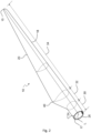
- Fig. 2 shows a schematic view of an exemplary wind turbine blade 10.
- the wind turbine blade 10 has the shape of a conventional wind turbine blade with a root end 17 and a tip end 15 and comprises a root region 30 closest to the hub, a profiled or an airfoil region 34 furthest away from the hub and a transition region 32 between the root region 30 and the airfoil region 34.
- the blade 10 comprises a leading edge 18 facing the direction of rotation of the blade 10, when the blade is mounted on the hub, and a trailing edge 20 facing the opposite direction of the leading edge 18.
- the root ends of the blade shell parts 24, 26 has a semi-circular or semi-oval outer cross-sectional shape.
- the blade shell parts 24, 26 define the aerodynamic shape of the wind turbine blade but require a main laminate to have the load carrying structure to support the weight of the wind turbine blade.
- Figure 3 shows a schematic view of a proximal and a distal mould 44, 46 for a first blade half shell part 24 of root and tip blade segments 11, 12, respectively, arranged end-to-end at a respective joint end 11a, 12a.
- a root blade shell part 24 is positioned on a mould surface of the proximal mould 11.
- a main laminate 50 is positioned on the blade shell part 24 and 50 is configured for forming the load carrying structure of the root blade segment 11 together with a corresponding second main laminate on a second blade shell part (not shown).
- the main laminates are intended to be connected via webs (not shown).
- the main laminate 50 extends in a spanwise direction L from a proximal end 51 through a transition region 52 to a distal end 53.
- the proximal end 51 of the main laminate 50 is located in the root region 30 of the root of the wind turbine blade and the distal end 53 of the main laminate 50 is located in the airfoil region 34 of the wind turbine blade 10.
- the transition region 52 of the main laminate 50 is located in the airfoil region 34 of the wind turbine blade 10.
- transition portion 60b of the pultrusion portion 60 and the transition portion 70b of the plurality of fibre-reinforced elements 70 are connected by a joint 80, 81, 82 in the transition region 52 of the main laminate 50, see Figs. 5a-6b .
- the plurality of fibre-reinforced elements 70 is a combination of non-pultruded preform elements and non-pultruded unidirectional sheets reinforced with carbon and glass fibres.
- the transition region 52 of the main laminate 55 is bounded by second and fifth locations 92, 95 along the spanwise extend of the main laminate 5.
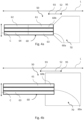
- the chordwise width of the plurality of fibre-reinforced elements 70 adjacent to the transition region 52 at the fifth location 95 of main laminate 50 is wider the chordwise width of the pultrusion portion 60 adjacent to the transition region 52 at the third location 93 of the main laminate 50 and a maximum width of the pultrusion portion 60 as can be seen in Figs. 4a-4b .
- the pultrusion portion 60 comprises first and second bottom pultrusion elements 61, 63 and further an intermediate bottom pultrusion element which are arranged in three rows, i.e. a first, an intermediate, and a second row, and a single column similarly to the arrangement in Fig. 4a but wherein the proximal and distal columns are combined in the single column.
- the plurality of fibre-reinforced elements 70 overlap with the pultrusion portion in the transition region 52 along the spanwise direction L.
- the plurality of fibre-reinforced elements has a constant width along the spanwise direction L.
- the joint between the transition end 60b of the pultrusion portion 60 and the transition end 70b of the plurality of fibre-reinforced elements 70 is a single spanwise scarf joint in which the transition end 60b of the pultrusion portion 60 tapers so that the bottom side 55 is longer than the top side 54 and the top side 54 of the top fibre-reinforced element 72 extends further than the bottom side 55 of the bottom fibre-reinforced element 71.
- the pultrusion portion 60 overlaps the plurality of fibre-reinforced elements 70 in the spanwise direction L.
- the main laminate 50 comprises first, second, third, fourth, fifth, and sixth locations 91, 92, 93, 94, 95, 96 located along the spanwise extent of the main laminate 50.
- the first location 91 is located at the proximal end of the main laminate 50 and the sixth location 96 is located at the distal end of the main laminate 50.
- the transition end 60a of the pultrusion portion 60 is located at the third location 93 and an opposite end, i.e. the proximal end, of the pultrusion portion 60 is located at the first location 91, and the second location 92 is located between the first and third locations 91, 93.
- the transition end 70a of the plurality of fibre-reinforced elements 70 is located at the fourth location 94, and an opposite end, i.e. the distal end, of the plurality of fibre-reinforced elements 70 is located at the sixth location 96, and the fifth location 95 is located between the fourth and sixth locations 94, 96.
- the second location 92 is located between the first and fourth locations 91, 94, and the fifth location 95 is located between the third and sixth locations 93, 96.
- the transition region 52 of the main laminate 55 is bounded by the second and the fifth locations 92, 95.
- the thickness of the pultrusion portion 60 in the thickness direction T adjacent to the transition region 52 at the third location 93 of the main laminate 50 is thicker than the thickness of the plurality of fibre-reinforced elements 70 in the thickness direction T adjacent to the transition region 52 at the fifth location 95 of the main laminate 50 and the maximum thickness of the plurality of fibre-reinforced elements 70 as seen in the Figs. 5a-5b .
- the joint between the transition end 60b of the pultrusion portion 60 and the transition end 70b of the plurality of fibre-reinforced elements 70 is a spanwise butt joint.
- the gap between transition ends 60b, 70b are shown for illustrative purposes, in practice the ends are arranged end-to-end without a gap.
- the third and fourth position 93, 94 would, if shown, coincide as the joint is a butt joint.
Landscapes
- Engineering & Computer Science (AREA)
- Mechanical Engineering (AREA)
- Chemical & Material Sciences (AREA)
- Life Sciences & Earth Sciences (AREA)
- Sustainable Development (AREA)
- Sustainable Energy (AREA)
- Combustion & Propulsion (AREA)
- General Engineering & Computer Science (AREA)
- Composite Materials (AREA)
- Physics & Mathematics (AREA)
- Fluid Mechanics (AREA)
- Wind Motors (AREA)
Claims (15)
- Stratifié principal (50) formant une structure porteuse de charge pour une pale d'éolienne (10), le stratifié principal s'étendant dans une direction allant dans le sens de l'envergure (L) depuis une extrémité proximale (51) à travers une région de transition (52) jusqu'à une extrémité distale (53), dans lequel le stratifié principal comporte :- un côté supérieur (54) configuré pour être orienté vers la partie intérieure de la pale d'éolienne, un côté inférieur (55) opposé au côté supérieur, et une direction (T) allant dans le sens de l'épaisseur s'étendant entre le côté supérieur et le côté inférieur ;- une partie de pultrusion (60) comprenant un élément de pultrusion inférieur (61, 62) s'étendant dans la direction allant dans le sens de l'envergure depuis l'extrémité proximale jusqu'à une extrémité de transition (60a) se trouvant dans la région de transition du stratifié principal, la partie de pultrusion ayant une partie de transition (60b) à l'extrémité de transition, l'élément de pultrusion inférieur formant une première partie du côté inférieur du stratifié principal ;- une pluralité d'éléments (70) renforcés par des fibres comprenant des éléments inférieur et supérieur (71, 72) renforcés par des fibres s'étendant dans la direction allant dans le sens de l'envergure depuis l'extrémité distale jusqu'à une extrémité de transition (70a) se trouvant dans la région de transition du stratifié principal, la pluralité d'éléments renforcés par des fibres ayant une partie de transition (70b) à l'extrémité de transition, l'élément inférieur renforcé par des fibres formant une deuxième partie du côté inférieur du stratifié principal, les éléments de la pluralité d'éléments renforcés par des fibres étant empilés dans la direction allant dans le sens de l'épaisseur, depuis l'élément inférieur renforcé par des fibres jusqu'à l'élément supérieur renforcé par des fibres ;dans lequel la partie de transition de la partie de pultrusion et la partie de transition de la pluralité d'éléments renforcés par des fibres sont reliées par un joint (80) dans la région de transition du stratifié principal, caractérisé par un côté sens de la corde de la partie de transition de la partie de pultrusion et un côté sens de la corde de la partie de transition de la pluralité d'éléments renforcés par des fibres reliés par un joint (81, 82).
- Stratifié principal selon l'une quelconque des revendications précédentes, dans lequel la pluralité d'éléments renforcés par des fibres se présente sous la forme d'au moins une feuille renforcée par des fibres, d'au moins une couche renforcée par des fibres et/ou d'au moins un élément préformé renforcé par des fibres.
- Stratifié principal selon l'une quelconque des revendications précédentes, dans lequel la partie de pultrusion comporte un élément de pultrusion supérieur (65, 66) formant une partie du côté supérieur du stratifié principal, les éléments de pultrusion étant empilés dans la direction allant dans le sens de l'épaisseur depuis l'élément de pultrusion inférieur jusqu'à l'élément de pultrusion supérieur.
- Stratifié principal selon l'une quelconque des revendications précédentes, dans lequel l'élément de pultrusion inférieur est un premier élément de pultrusion inférieur (61, 62), et dans lequel la partie de pultrusion comporte un deuxième élément de pultrusion inférieur (63, 64) agencé côte à côte dans le sens de la corde avec le premier élément de pultrusion inférieur.
- Stratifié principal selon l'une quelconque des revendications précédentes, dans lequel l'élément de pultrusion inférieur est un élément de pultrusion inférieur distal (61, 63), et dans lequel la partie de pultrusion comporte un élément de pultrusion inférieur proximal (62, 64) agencé bout à bout et dans le prolongement de l'élément de pultrusion inférieur distal.
- Stratifié principal selon l'une quelconque des revendications précédentes, dans lequel le joint est un joint en biseau, de préférence un joint en biseau unique.
- Stratifié principal selon l'une quelconque des revendications précédentes, dans lequel le côté sens de la corde de la partie de transition de la partie de pultrusion et le côté sens de la corde de la partie de transition de la pluralité d'éléments renforcés par des fibres sont reliés par un joint en biseau (81, 82).
- Stratifié principal selon l'une quelconque des revendications précédentes, comportant des premier, deuxième, troisième, quatrième, cinquième et sixième emplacements (91, 92, 93, 94, 95, 96) se trouvant le long de l'étendue allant dans le sens de l'envergure du stratifié principal, le premier emplacement (91) se trouvant à l'extrémité proximale du stratifié principal et le sixième emplacement (96) se trouvant à l'extrémité distale du stratifié principal, la région de transition du stratifié principal étant délimitée par le deuxième emplacement (92) et le cinquième emplacement (95),dans lequel l'extrémité de transition de la partie de pultrusion se trouve au niveau du troisième emplacement (93) et une extrémité opposée de la partie de pultrusion se trouve au niveau du premier emplacement, le deuxième emplacement (92) se trouve entre les premier et troisième emplacements, etdans lequel l'extrémité de transition de la pluralité d'éléments renforcés par des fibres peut se trouver au niveau du quatrième emplacement (94), et une extrémité opposée de la pluralité d'éléments renforcés par des fibres peut se trouver au niveau du sixième emplacement, le cinquième emplacement se trouvant entre les quatrième et sixième emplacements.
- Pale d'éolienne (10) s'étendant le long d'un axe longitudinal (L) depuis un pied (17) jusqu'à un bout (15), la pale d'éolienne comprenant une région de pied (30) et une région de profil aérodynamique (34) avec le bout, la pale d'éolienne comportant un côté en pression (24), un côté en dépression (26), et une ligne de corde (C) s'étendant entre un bord d'attaque (18) et un bord de fuite (20), la pale d'éolienne comportant une coque (13) conférant la forme aérodynamique de la pale d'éolienne et un stratifié principal (50) selon l'une quelconque des revendications précédentes, le stratifié principal formant une structure porteuse de charge de la pale d'éolienne et le côté inférieur du stratifié principal étant positionné sur la coque.
- Pale d'éolienne selon la revendication précédente, dans laquelle l'extrémité proximale du stratifié principal se trouve dans la région de pied ou au niveau du pied de la pale d'éolienne et l'extrémité distale du stratifié principal se trouve dans la région de profil aérodynamique ou au niveau du bout de la pale d'éolienne, et dans laquelle la région de transition du stratifié principal se trouve dans la région de profil aérodynamique de la pale d'éolienne.
- Segment de pale d'éolienne pour une pale d'éolienne selon l'une quelconque des revendications 9 à 10, dans lequel le segment de pale d'éolienne s'étendant le long d'un axe longitudinal depuis un pied jusqu'à une extrémité distale configurée à des fins de raccordement avec un autre segment de pale d'éolienne, éventuellement par un joint articulé, le segment de pale d'éolienne comportant une région de pied et une région de profil aérodynamique avec l'extrémité distale, la pale d'éolienne comportant un côté en pression, un côté en dépression et une ligne de corde s'étendant entre un bord d'attaque et un bord de fuite, le segment de pale d'éolienne comportant une coque définissant la forme aérodynamique du segment de pale d'éolienne et un stratifié principal selon l'une quelconque des revendications 1 à 8, le stratifié principal formant une structure porteuse de charge du segment de pale d'éolienne et le côté inférieur du stratifié principal est positionné sur la coque.
- Segment de pale d'éolienne selon la revendication 11, dans lequel l'extrémité proximale du stratifié principal se trouve dans la région de pied ou au niveau du pied du segment de pale d'éolienne et l'extrémité distale du stratifié principal se trouve dans la région de profil aérodynamique ou à l'extrémité distale du segment de pale d'éolienne, et dans lequel la région de transition du stratifié principal se trouve dans la région de profil aérodynamique du segment de pale d'éolienne.
- Procédé de fabrication d'un stratifié principal pour une pale d'éolienne, le stratifié principal s'étendant dans une direction allant dans le sens de l'envergure depuis une extrémité proximale à travers une région de transition jusqu'à une extrémité distale et comportant un côté inférieur configuré pour être orienté vers une coque de la pale d'éolienne, un côté supérieur configuré pour être orienté vers la partie intérieure de la pale d'éolienne, et une direction allant dans le sens de l'épaisseur s'étendant entre le côté inférieur et le côté supérieur, le procédé comportant les étapes consistant à :- fournir :o une partie de pultrusion comprenant un élément de pultrusion inférieur s'étendant dans la direction allant dans le sens de l'envergure jusqu'à une extrémité de transition, la partie de pultrusion ayant une partie de transition à l'extrémité de transition, eto une pluralité d'éléments renforcés par des fibres comprenant des éléments inférieur et supérieur renforcés par des fibres s'étendant dans la direction allant dans le sens de l'envergure jusqu' à une extrémité de transition, la pluralité d'éléments renforcés par des fibres ayant une partie de transition à l'extrémité de transition ;- positionner l'élément de pultrusion inférieur et l'élément inférieur renforcé par des fibres dans le prolongement l'un de l'autre, de telle sorte que l'extrémité de transition de l'élément inférieur renforcé par des fibres est adjacente par rapport à l'extrémité de transition de l'élément de pultrusion inférieur et est orientée vers celle-ci ;- empiler la pluralité d'éléments renforcés par des fibres dans la direction allant dans le sens de l'épaisseur, depuis l'élément inférieur renforcé par des fibres jusqu'à l'élément supérieur renforcé par des fibres ;- faire durcir la partie de pultrusion et la pluralité d'éléments renforcés par des fibres pour de ce fait former un joint entre la partie de transition de la partie de pultrusion et la partie de transition de la pluralité d'éléments renforcés par des fibres et relier un côté sens de la corde de la partie de transition de la partie de pultrusion et un côté sens de la corde de la partie de transition de la pluralité d'éléments renforcés par des fibres par un j oint, de préférence un j oint en biseau.
- Procédé de fabrication d'une pale d'éolienne s'étendant le long d'un axe longitudinal depuis un pied jusqu'à un bout, la pale d'éolienne comportant une région de pied et une région de profil aérodynamique avec le bout, la pale d'éolienne comportant un côté en pression, un côté en dépression et une ligne de corde s'étendant entre un bord d'attaque et un bord de fuite, la pale d'éolienne comportant une coque conférant la forme aérodynamique de la pale d'éolienne et un stratifié principal formant une structure porteuse de charge de la pale d'éolienne, le procédé comportant les étapes consistant à :- fournir une coque configurée pour conférer la forme aérodynamique de la pale d'éolienne,- effectuer un procédé selon la revendication 13, dans lequel l'élément de pultrusion inférieur et l'élément inférieur renforcé par des fibres sont positionnés dans le prolongement l'un de l'autre sur la coque de la pale d'éolienne.
- Procédé selon l'une quelconque des revendications 13 à 14, dans lequel la partie de pultrusion est une pluralité d'éléments de pultrusion comprenant l'élément de pultrusion inférieur et un élément de pultrusion supérieur, la pluralité d'éléments de pultrusion s'étendant dans la direction allant dans le sens de l'envergure vers l'extrémité de transition de la partie de pultrusion, et dans lequel l'étape consistant à positionner la partie de pultrusion comporte l'étape consistant à :- empiler la pluralité d'éléments de pultrusion dans la direction allant dans le sens de l'épaisseur depuis l'élément de pultrusion inférieur jusqu'à l'élément de pultrusion supérieur de telle sorte que l'extrémité de transition de la partie de pultrusion est positionnée de manière adjacente par rapport à l'extrémité de transition de la pluralité d'éléments renforcés par des fibres.
Priority Applications (1)
| Application Number | Priority Date | Filing Date | Title |
|---|---|---|---|
| PL20722221.7T PL4132776T3 (pl) | 2020-04-07 | 2020-04-07 | Laminat główny, łopata turbiny wiatrowej zawierająca taki laminat główny i sposoby wytwarzania |
Applications Claiming Priority (1)
| Application Number | Priority Date | Filing Date | Title |
|---|---|---|---|
| PCT/EP2020/059844 WO2021204357A1 (fr) | 2020-04-07 | 2020-04-07 | Stratifié principal |
Publications (2)
| Publication Number | Publication Date |
|---|---|
| EP4132776A1 EP4132776A1 (fr) | 2023-02-15 |
| EP4132776B1 true EP4132776B1 (fr) | 2024-07-03 |
Family
ID=70470976
Family Applications (1)
| Application Number | Title | Priority Date | Filing Date |
|---|---|---|---|
| EP20722221.7A Active EP4132776B1 (fr) | 2020-04-07 | 2020-04-07 | Stratifié principal, pale d'éolienne comprenant un tel stratifié principal et procédés de fabrications. |
Country Status (7)
| Country | Link |
|---|---|
| US (1) | US12005655B2 (fr) |
| EP (1) | EP4132776B1 (fr) |
| CN (1) | CN114096400A (fr) |
| DK (1) | DK4132776T3 (fr) |
| ES (1) | ES2989668T3 (fr) |
| PL (1) | PL4132776T3 (fr) |
| WO (1) | WO2021204357A1 (fr) |
Families Citing this family (1)
| Publication number | Priority date | Publication date | Assignee | Title |
|---|---|---|---|---|
| CN118715363A (zh) * | 2021-12-21 | 2024-09-27 | 维斯塔斯风力系统有限公司 | 风轮机叶片 |
Family Cites Families (7)
| Publication number | Priority date | Publication date | Assignee | Title |
|---|---|---|---|---|
| US20140271217A1 (en) * | 2013-03-15 | 2014-09-18 | Modular Wind Energy, Inc. | Efficient wind turbine blade design and associated manufacturing methods using rectangular spars and segmented shear web |
| US20160160837A1 (en) * | 2014-12-04 | 2016-06-09 | General Electric Company | Pultruded rotor blade components having interlocking edges |
| US10465653B2 (en) * | 2017-06-21 | 2019-11-05 | General Electric Company | Wind turbine blade with hybrid spar cap and associated method for making |
| US11506171B2 (en) | 2018-06-11 | 2022-11-22 | Vestas Wind Systems A/S | Wind turbine blade spar structure and method of manufacturing |
| EP3643912B1 (fr) * | 2018-10-25 | 2025-10-15 | LM Wind Power A/S | Pale d'éolienne comportant plusieurs capuchons de longeron |
| AU2018446413A1 (en) | 2018-10-25 | 2021-05-27 | General Electric Renovables España, S.L. | Spar cap configuration for a jointed wind turbine blade |
| CN113840719A (zh) | 2019-03-29 | 2021-12-24 | Lm风力发电公司 | 风力涡轮机叶片的增强壳体部件的制造 |
-
2020
- 2020-04-07 ES ES20722221T patent/ES2989668T3/es active Active
- 2020-04-07 DK DK20722221.7T patent/DK4132776T3/da active
- 2020-04-07 CN CN202080001027.6A patent/CN114096400A/zh active Pending
- 2020-04-07 EP EP20722221.7A patent/EP4132776B1/fr active Active
- 2020-04-07 PL PL20722221.7T patent/PL4132776T3/pl unknown
- 2020-04-07 WO PCT/EP2020/059844 patent/WO2021204357A1/fr not_active Ceased
- 2020-04-07 US US17/801,363 patent/US12005655B2/en active Active
Also Published As
| Publication number | Publication date |
|---|---|
| US20230071090A1 (en) | 2023-03-09 |
| CN114096400A (zh) | 2022-02-25 |
| ES2989668T3 (es) | 2024-11-27 |
| US12005655B2 (en) | 2024-06-11 |
| PL4132776T3 (pl) | 2025-01-13 |
| DK4132776T3 (da) | 2024-09-23 |
| EP4132776A1 (fr) | 2023-02-15 |
| WO2021204357A1 (fr) | 2021-10-14 |
Similar Documents
| Publication | Publication Date | Title |
|---|---|---|
| EP3488100B1 (fr) | Pale d'éolienne avec segment de dos plat et procédé associé | |
| CN107636303B (zh) | 具有后缘间隔部分的风力涡轮机叶片 | |
| EP3112668A1 (fr) | Section de pied de pale pour pale de rotor modulaire et son procédé de fabrication | |
| US12546285B2 (en) | Wind turbine blade | |
| EP4135970B1 (fr) | Procédé de fabrication d'une pale d'éolienne à l'aide d'un ensemble de chauffage d'air | |
| US12392317B2 (en) | Wind turbine blade and method for producing a wind turbine blade | |
| US12049865B2 (en) | Wind turbine blade with a plurality of shear webs | |
| EP4150205B1 (fr) | Section de coque de pale et pale d'éolienne comprenant une section de coque de pale | |
| EP4132776B1 (fr) | Stratifié principal, pale d'éolienne comprenant un tel stratifié principal et procédés de fabrications. | |
| US20240018938A1 (en) | Wind turbine blade having buckling-resistant spar caps | |
| EP4174310B1 (fr) | Pale d'éolienne segmentée | |
| EP4013959B1 (fr) | Ensemble pale d'éolienne et procédé de production d'une pale d'éolienne | |
| EP4707584A1 (fr) | Pale de rotor d'éolienne et procédé de fabrication d'une pale de rotor d'éolienne | |
| CA3031137C (fr) | Pale d'eolienne avec segment de dos plat et procede associe | |
| WO2025185842A1 (fr) | Procédés de modernisation ou de fabrication d'une pale d'éolienne ou d'une partie pale d'éolienne |
Legal Events
| Date | Code | Title | Description |
|---|---|---|---|
| STAA | Information on the status of an ep patent application or granted ep patent |
Free format text: STATUS: UNKNOWN |
|
| STAA | Information on the status of an ep patent application or granted ep patent |
Free format text: STATUS: THE INTERNATIONAL PUBLICATION HAS BEEN MADE |
|
| PUAI | Public reference made under article 153(3) epc to a published international application that has entered the european phase |
Free format text: ORIGINAL CODE: 0009012 |
|
| STAA | Information on the status of an ep patent application or granted ep patent |
Free format text: STATUS: REQUEST FOR EXAMINATION WAS MADE |
|
| 17P | Request for examination filed |
Effective date: 20221104 |
|
| AK | Designated contracting states |
Kind code of ref document: A1 Designated state(s): AL AT BE BG CH CY CZ DE DK EE ES FI FR GB GR HR HU IE IS IT LI LT LU LV MC MK MT NL NO PL PT RO RS SE SI SK SM TR |
|
| P01 | Opt-out of the competence of the unified patent court (upc) registered |
Effective date: 20230522 |
|
| DAX | Request for extension of the european patent (deleted) | ||
| RAV | Requested validation state of the european patent: fee paid |
Extension state: MA Effective date: 20221104 |
|
| GRAP | Despatch of communication of intention to grant a patent |
Free format text: ORIGINAL CODE: EPIDOSNIGR1 |
|
| STAA | Information on the status of an ep patent application or granted ep patent |
Free format text: STATUS: GRANT OF PATENT IS INTENDED |
|
| INTG | Intention to grant announced |
Effective date: 20231013 |
|
| GRAJ | Information related to disapproval of communication of intention to grant by the applicant or resumption of examination proceedings by the epo deleted |
Free format text: ORIGINAL CODE: EPIDOSDIGR1 |
|
| STAA | Information on the status of an ep patent application or granted ep patent |
Free format text: STATUS: REQUEST FOR EXAMINATION WAS MADE |
|
| INTC | Intention to grant announced (deleted) | ||
| GRAP | Despatch of communication of intention to grant a patent |
Free format text: ORIGINAL CODE: EPIDOSNIGR1 |
|
| STAA | Information on the status of an ep patent application or granted ep patent |
Free format text: STATUS: GRANT OF PATENT IS INTENDED |
|
| INTG | Intention to grant announced |
Effective date: 20240222 |
|
| GRAS | Grant fee paid |
Free format text: ORIGINAL CODE: EPIDOSNIGR3 |
|
| GRAA | (expected) grant |
Free format text: ORIGINAL CODE: 0009210 |
|
| STAA | Information on the status of an ep patent application or granted ep patent |
Free format text: STATUS: THE PATENT HAS BEEN GRANTED |
|
| AK | Designated contracting states |
Kind code of ref document: B1 Designated state(s): AL AT BE BG CH CY CZ DE DK EE ES FI FR GB GR HR HU IE IS IT LI LT LU LV MC MK MT NL NO PL PT RO RS SE SI SK SM TR |
|
| REG | Reference to a national code |
Ref country code: CH Ref legal event code: EP |
|
| REG | Reference to a national code |
Ref country code: DE Ref legal event code: R096 Ref document number: 602020033309 Country of ref document: DE |
|
| REG | Reference to a national code |
Ref country code: DK Ref legal event code: T3 Effective date: 20240918 |
|
| REG | Reference to a national code |
Ref country code: LT Ref legal event code: MG9D |
|
| REG | Reference to a national code |
Ref country code: NL Ref legal event code: MP Effective date: 20240703 |
|
| REG | Reference to a national code |
Ref country code: ES Ref legal event code: FG2A Ref document number: 2989668 Country of ref document: ES Kind code of ref document: T3 Effective date: 20241127 |
|
| PG25 | Lapsed in a contracting state [announced via postgrant information from national office to epo] |
Ref country code: PT Free format text: LAPSE BECAUSE OF FAILURE TO SUBMIT A TRANSLATION OF THE DESCRIPTION OR TO PAY THE FEE WITHIN THE PRESCRIBED TIME-LIMIT Effective date: 20241104 |
|
| REG | Reference to a national code |
Ref country code: AT Ref legal event code: MK05 Ref document number: 1699412 Country of ref document: AT Kind code of ref document: T Effective date: 20240703 |
|
| PG25 | Lapsed in a contracting state [announced via postgrant information from national office to epo] |
Ref country code: NL Free format text: LAPSE BECAUSE OF FAILURE TO SUBMIT A TRANSLATION OF THE DESCRIPTION OR TO PAY THE FEE WITHIN THE PRESCRIBED TIME-LIMIT Effective date: 20240703 |
|
| PG25 | Lapsed in a contracting state [announced via postgrant information from national office to epo] |
Ref country code: PT Free format text: LAPSE BECAUSE OF FAILURE TO SUBMIT A TRANSLATION OF THE DESCRIPTION OR TO PAY THE FEE WITHIN THE PRESCRIBED TIME-LIMIT Effective date: 20241104 Ref country code: NL Free format text: LAPSE BECAUSE OF FAILURE TO SUBMIT A TRANSLATION OF THE DESCRIPTION OR TO PAY THE FEE WITHIN THE PRESCRIBED TIME-LIMIT Effective date: 20240703 |
|
| PG25 | Lapsed in a contracting state [announced via postgrant information from national office to epo] |
Ref country code: NO Free format text: LAPSE BECAUSE OF FAILURE TO SUBMIT A TRANSLATION OF THE DESCRIPTION OR TO PAY THE FEE WITHIN THE PRESCRIBED TIME-LIMIT Effective date: 20241003 |
|
| PG25 | Lapsed in a contracting state [announced via postgrant information from national office to epo] |
Ref country code: FI Free format text: LAPSE BECAUSE OF FAILURE TO SUBMIT A TRANSLATION OF THE DESCRIPTION OR TO PAY THE FEE WITHIN THE PRESCRIBED TIME-LIMIT Effective date: 20240703 Ref country code: GR Free format text: LAPSE BECAUSE OF FAILURE TO SUBMIT A TRANSLATION OF THE DESCRIPTION OR TO PAY THE FEE WITHIN THE PRESCRIBED TIME-LIMIT Effective date: 20241004 |
|
| PG25 | Lapsed in a contracting state [announced via postgrant information from national office to epo] |
Ref country code: BG Free format text: LAPSE BECAUSE OF FAILURE TO SUBMIT A TRANSLATION OF THE DESCRIPTION OR TO PAY THE FEE WITHIN THE PRESCRIBED TIME-LIMIT Effective date: 20240703 |
|
| PG25 | Lapsed in a contracting state [announced via postgrant information from national office to epo] |
Ref country code: LV Free format text: LAPSE BECAUSE OF FAILURE TO SUBMIT A TRANSLATION OF THE DESCRIPTION OR TO PAY THE FEE WITHIN THE PRESCRIBED TIME-LIMIT Effective date: 20240703 |
|
| PG25 | Lapsed in a contracting state [announced via postgrant information from national office to epo] |
Ref country code: IS Free format text: LAPSE BECAUSE OF FAILURE TO SUBMIT A TRANSLATION OF THE DESCRIPTION OR TO PAY THE FEE WITHIN THE PRESCRIBED TIME-LIMIT Effective date: 20241103 Ref country code: AT Free format text: LAPSE BECAUSE OF FAILURE TO SUBMIT A TRANSLATION OF THE DESCRIPTION OR TO PAY THE FEE WITHIN THE PRESCRIBED TIME-LIMIT Effective date: 20240703 |
|
| PG25 | Lapsed in a contracting state [announced via postgrant information from national office to epo] |
Ref country code: HR Free format text: LAPSE BECAUSE OF FAILURE TO SUBMIT A TRANSLATION OF THE DESCRIPTION OR TO PAY THE FEE WITHIN THE PRESCRIBED TIME-LIMIT Effective date: 20240703 Ref country code: CZ Free format text: LAPSE BECAUSE OF FAILURE TO SUBMIT A TRANSLATION OF THE DESCRIPTION OR TO PAY THE FEE WITHIN THE PRESCRIBED TIME-LIMIT Effective date: 20240703 |
|
| PG25 | Lapsed in a contracting state [announced via postgrant information from national office to epo] |
Ref country code: RS Free format text: LAPSE BECAUSE OF FAILURE TO SUBMIT A TRANSLATION OF THE DESCRIPTION OR TO PAY THE FEE WITHIN THE PRESCRIBED TIME-LIMIT Effective date: 20241003 |
|
| PG25 | Lapsed in a contracting state [announced via postgrant information from national office to epo] |
Ref country code: RS Free format text: LAPSE BECAUSE OF FAILURE TO SUBMIT A TRANSLATION OF THE DESCRIPTION OR TO PAY THE FEE WITHIN THE PRESCRIBED TIME-LIMIT Effective date: 20241003 Ref country code: NO Free format text: LAPSE BECAUSE OF FAILURE TO SUBMIT A TRANSLATION OF THE DESCRIPTION OR TO PAY THE FEE WITHIN THE PRESCRIBED TIME-LIMIT Effective date: 20241003 Ref country code: LV Free format text: LAPSE BECAUSE OF FAILURE TO SUBMIT A TRANSLATION OF THE DESCRIPTION OR TO PAY THE FEE WITHIN THE PRESCRIBED TIME-LIMIT Effective date: 20240703 Ref country code: IS Free format text: LAPSE BECAUSE OF FAILURE TO SUBMIT A TRANSLATION OF THE DESCRIPTION OR TO PAY THE FEE WITHIN THE PRESCRIBED TIME-LIMIT Effective date: 20241103 Ref country code: HR Free format text: LAPSE BECAUSE OF FAILURE TO SUBMIT A TRANSLATION OF THE DESCRIPTION OR TO PAY THE FEE WITHIN THE PRESCRIBED TIME-LIMIT Effective date: 20240703 Ref country code: GR Free format text: LAPSE BECAUSE OF FAILURE TO SUBMIT A TRANSLATION OF THE DESCRIPTION OR TO PAY THE FEE WITHIN THE PRESCRIBED TIME-LIMIT Effective date: 20241004 Ref country code: FI Free format text: LAPSE BECAUSE OF FAILURE TO SUBMIT A TRANSLATION OF THE DESCRIPTION OR TO PAY THE FEE WITHIN THE PRESCRIBED TIME-LIMIT Effective date: 20240703 Ref country code: CZ Free format text: LAPSE BECAUSE OF FAILURE TO SUBMIT A TRANSLATION OF THE DESCRIPTION OR TO PAY THE FEE WITHIN THE PRESCRIBED TIME-LIMIT Effective date: 20240703 Ref country code: BG Free format text: LAPSE BECAUSE OF FAILURE TO SUBMIT A TRANSLATION OF THE DESCRIPTION OR TO PAY THE FEE WITHIN THE PRESCRIBED TIME-LIMIT Effective date: 20240703 Ref country code: AT Free format text: LAPSE BECAUSE OF FAILURE TO SUBMIT A TRANSLATION OF THE DESCRIPTION OR TO PAY THE FEE WITHIN THE PRESCRIBED TIME-LIMIT Effective date: 20240703 |
|
| REG | Reference to a national code |
Ref country code: DE Ref legal event code: R097 Ref document number: 602020033309 Country of ref document: DE |
|
| PG25 | Lapsed in a contracting state [announced via postgrant information from national office to epo] |
Ref country code: SM Free format text: LAPSE BECAUSE OF FAILURE TO SUBMIT A TRANSLATION OF THE DESCRIPTION OR TO PAY THE FEE WITHIN THE PRESCRIBED TIME-LIMIT Effective date: 20240703 Ref country code: RO Free format text: LAPSE BECAUSE OF FAILURE TO SUBMIT A TRANSLATION OF THE DESCRIPTION OR TO PAY THE FEE WITHIN THE PRESCRIBED TIME-LIMIT Effective date: 20240703 |
|
| PG25 | Lapsed in a contracting state [announced via postgrant information from national office to epo] |
Ref country code: EE Free format text: LAPSE BECAUSE OF FAILURE TO SUBMIT A TRANSLATION OF THE DESCRIPTION OR TO PAY THE FEE WITHIN THE PRESCRIBED TIME-LIMIT Effective date: 20240703 |
|
| PG25 | Lapsed in a contracting state [announced via postgrant information from national office to epo] |
Ref country code: SK Free format text: LAPSE BECAUSE OF FAILURE TO SUBMIT A TRANSLATION OF THE DESCRIPTION OR TO PAY THE FEE WITHIN THE PRESCRIBED TIME-LIMIT Effective date: 20240703 Ref country code: IT Free format text: LAPSE BECAUSE OF FAILURE TO SUBMIT A TRANSLATION OF THE DESCRIPTION OR TO PAY THE FEE WITHIN THE PRESCRIBED TIME-LIMIT Effective date: 20240703 |
|
| PLBE | No opposition filed within time limit |
Free format text: ORIGINAL CODE: 0009261 |
|
| STAA | Information on the status of an ep patent application or granted ep patent |
Free format text: STATUS: NO OPPOSITION FILED WITHIN TIME LIMIT |
|
| 26N | No opposition filed |
Effective date: 20250404 |
|
| PGFP | Annual fee paid to national office [announced via postgrant information from national office to epo] |
Ref country code: DE Payment date: 20250319 Year of fee payment: 6 |
|
| PGFP | Annual fee paid to national office [announced via postgrant information from national office to epo] |
Ref country code: ES Payment date: 20250502 Year of fee payment: 6 |
|
| PG25 | Lapsed in a contracting state [announced via postgrant information from national office to epo] |
Ref country code: SE Free format text: LAPSE BECAUSE OF FAILURE TO SUBMIT A TRANSLATION OF THE DESCRIPTION OR TO PAY THE FEE WITHIN THE PRESCRIBED TIME-LIMIT Effective date: 20240703 |
|
| REG | Reference to a national code |
Ref country code: CH Ref legal event code: H13 Free format text: ST27 STATUS EVENT CODE: U-0-0-H10-H13 (AS PROVIDED BY THE NATIONAL OFFICE) Effective date: 20251125 |
|
| PG25 | Lapsed in a contracting state [announced via postgrant information from national office to epo] |
Ref country code: LU Free format text: LAPSE BECAUSE OF NON-PAYMENT OF DUE FEES Effective date: 20250407 |
|
| PG25 | Lapsed in a contracting state [announced via postgrant information from national office to epo] |
Ref country code: MC Free format text: LAPSE BECAUSE OF FAILURE TO SUBMIT A TRANSLATION OF THE DESCRIPTION OR TO PAY THE FEE WITHIN THE PRESCRIBED TIME-LIMIT Effective date: 20240703 |
|
| REG | Reference to a national code |
Ref country code: BE Ref legal event code: MM Effective date: 20250430 |
|
| PG25 | Lapsed in a contracting state [announced via postgrant information from national office to epo] |
Ref country code: BE Free format text: LAPSE BECAUSE OF NON-PAYMENT OF DUE FEES Effective date: 20250430 |
|
| PG25 | Lapsed in a contracting state [announced via postgrant information from national office to epo] |
Ref country code: CH Free format text: LAPSE BECAUSE OF NON-PAYMENT OF DUE FEES Effective date: 20250430 |
|
| PGFP | Annual fee paid to national office [announced via postgrant information from national office to epo] |
Ref country code: GB Payment date: 20260319 Year of fee payment: 7 |
|
| PG25 | Lapsed in a contracting state [announced via postgrant information from national office to epo] |
Ref country code: IE Free format text: LAPSE BECAUSE OF NON-PAYMENT OF DUE FEES Effective date: 20250407 |
|
| PGFP | Annual fee paid to national office [announced via postgrant information from national office to epo] |
Ref country code: DK Payment date: 20260319 Year of fee payment: 7 |
|
| PGFP | Annual fee paid to national office [announced via postgrant information from national office to epo] |
Ref country code: FR Payment date: 20260319 Year of fee payment: 7 |
|
| PGFP | Annual fee paid to national office [announced via postgrant information from national office to epo] |
Ref country code: PL Payment date: 20260320 Year of fee payment: 7 |