EP4132777B1 - Presse radiale - Google Patents
Presse radiale Download PDFInfo
- Publication number
- EP4132777B1 EP4132777B1 EP21746743.0A EP21746743A EP4132777B1 EP 4132777 B1 EP4132777 B1 EP 4132777B1 EP 21746743 A EP21746743 A EP 21746743A EP 4132777 B1 EP4132777 B1 EP 4132777B1
- Authority
- EP
- European Patent Office
- Prior art keywords
- press
- ring structure
- radial
- radial press
- cylinder
- Prior art date
- Legal status (The legal status is an assumption and is not a legal conclusion. Google has not performed a legal analysis and makes no representation as to the accuracy of the status listed.)
- Active
Links
Images

Classifications
-
- B—PERFORMING OPERATIONS; TRANSPORTING
- B30—PRESSES
- B30B—PRESSES IN GENERAL
- B30B7/00—Presses characterised by a particular arrangement of the pressing members
- B30B7/04—Presses characterised by a particular arrangement of the pressing members wherein pressing is effected in different directions simultaneously or in turn
-
- B—PERFORMING OPERATIONS; TRANSPORTING
- B30—PRESSES
- B30B—PRESSES IN GENERAL
- B30B1/00—Presses, using a press ram, characterised by the features of the drive therefor, pressure being transmitted directly, or through simple thrust or tension members only, to the press ram or platen
- B30B1/007—Presses, using a press ram, characterised by the features of the drive therefor, pressure being transmitted directly, or through simple thrust or tension members only, to the press ram or platen using a fluid connection between the drive means and the press ram
-
- B—PERFORMING OPERATIONS; TRANSPORTING
- B30—PRESSES
- B30B—PRESSES IN GENERAL
- B30B1/00—Presses, using a press ram, characterised by the features of the drive therefor, pressure being transmitted directly, or through simple thrust or tension members only, to the press ram or platen
- B30B1/40—Presses, using a press ram, characterised by the features of the drive therefor, pressure being transmitted directly, or through simple thrust or tension members only, to the press ram or platen by wedge means
-
- B—PERFORMING OPERATIONS; TRANSPORTING
- B30—PRESSES
- B30B—PRESSES IN GENERAL
- B30B15/00—Details of, or accessories for, presses; Auxiliary measures in connection with pressing
- B30B15/04—Frames; Guides
- B30B15/041—Guides
-
- B—PERFORMING OPERATIONS; TRANSPORTING
- B30—PRESSES
- B30B—PRESSES IN GENERAL
- B30B15/00—Details of, or accessories for, presses; Auxiliary measures in connection with pressing
- B30B15/06—Platens or press rams
- B30B15/062—Press plates
-
- B—PERFORMING OPERATIONS; TRANSPORTING
- B30—PRESSES
- B30B—PRESSES IN GENERAL
- B30B15/00—Details of, or accessories for, presses; Auxiliary measures in connection with pressing
- B30B15/06—Platens or press rams
- B30B15/068—Drive connections, e.g. pivotal
Definitions
- the present invention relates, as stated in the preamble of claim 1, to a radial press with a first and a second ring structure extending around a press axis and a plurality of pressed bodies arranged between these around the press axis and slidably supported on the support surfaces assigned to the ring structures, the
- the axial distance between the two ring structures can be changed by means of a drive system, which comprises a plurality of actuators oriented parallel to the press axis and distributed around it, each of which has a first component with a first of the two ring structures and one that is actively movable with respect to the first component second component are coupled to the second ring structure, and furthermore at least the support surfaces assigned to one of the two ring structures are oriented inclined to the press axis and the pressed bodies are positively guided relative to the two ring structures.
- a workpiece arranged between the pressed bodies is accordingly deformed radially, with the degree of inclination of the support surfaces defining the ratio of the reduction in the axial movement of the ring structures to one another to the radial movement of the pressed bodies. If the two ring structures move away from each other when the drive system is operated in reverse to pressing, the pressed bodies move outwards again away from the pressing axis under the action of return springs arranged between two adjacent pressed bodies. The tool opens and the formed workpiece can be removed when the tool is fully open. Also the US 4,766,808 A discloses a radial press of the type explained above.
- annular cylinder-piston arrangement surrounding the press axis forms the core of the drive system;
- This annular cylinder-piston arrangement By means of this annular cylinder-piston arrangement, the movement of the two ring structures in the sense of bringing them closer together takes place during power pressing.
- Two additional Linear actuators provided, acting between the two ring structures, are used for rapid adjustment when closing and opening the press, ie the resetting of the two ring structures by moving them apart.
- the radial presses discussed above are equally compact and powerful and are characterized by several design-related advantages - especially compared to those of the yoke press design (see, for example, the "HM 325" radial press from Uniflex Hydraulik GmbH, Karben). This includes in particular that the press axis does not shift during the pressing process, which is particularly essential for automatic loading. Another advantage is the flexibility in terms of the number of compacts; if necessary, these can even be provided in an odd number.
- the present invention has set itself the task of providing a radial press of the generic type, which is particularly suitable under practical conditions for radial forming of particularly large workpieces with a particularly high pressing force and is superior to the prior art in such application, whereby - in
- a radial press suitable for pressing large workpieces ideally workpieces with dimensions that are significantly below the maximum dimension (in particular the maximum possible diameter) can also be reliably formed.
- this problem is solved in that the positive guidance takes place via pairings of guide grooves made on the pressed bodies and guide bodies comprising guide rollers which engage in these and are assigned to the respective ring structure.
- this is done according to the invention by positively guiding the pressed bodies on the two ring structures.
- the double, bilateral forced guidance of the pressed bodies according to the invention takes place via pairs of guide grooves assigned to the pressed bodies and the relevant ring structure and guide bodies engaging in them, the guide grooves being carried out on the pressed bodies and the guide bodies comprising guide rollers.
- the position of the pressed bodies is, in other words, clearly defined according to the invention by their specific forced guidance on the two ring structures, which is defined in more detail as claimed. Return springs acting between the pressed bodies can be omitted when implementing the invention.
- the positive guidance of the pressed bodies on the two ring structures is reflected in several significant practical advantages. For example, such a double, two-sided positive guidance of the pressed bodies prevents them from tipping - particularly as a result of an axially acting load.
- the resistance of the pressed bodies against tipping that can be achieved in this way makes the radial presses designed in this way suitable for the radial pressing of axially loaded workpieces.
- a radial press according to the invention which is suitable for pressing large workpieces, can also reliably shape workpieces with dimensions that are significantly below the maximum dimension if the press bodies are adapted accordingly (e.g. by exchanging replaceable pressing jaws; see below).
- the forced guidance of the pressed bodies on both sides - when opening the radial press - reliably prevents anything happening in the direction of the press axis Lifting of the pressed bodies from the support surfaces inclined relative to the press axis as a result of radially inward forces.
- the invention also provides a solution for the danger - depending on the specific contour of the workpiece surface in the forming area and the material used, especially when forming large workpieces - of such forces ("extraction forces") caused by the clamping of the pressed bodies on the workpiece surface, which, in extreme cases, can cause considerable damage to conventional radial presses equipped with return springs.
- the restoring springs must provide very large restoring forces. These may cause a substantial reduction in the forming force that can be effectively applied to the workpiece.
- the drive system is designed hydraulically, in that the actuators - which are oriented parallel to the press axis and are arranged distributed around it - are designed as hydraulic cylinder-piston units, of which the cylinder transmits the force with the first ring structure coupled first component and the piston rod forms the second component of the relevant actuator, which is coupled to the second ring structure in a force-transmitting manner.
- the advantages set out above that can be achieved with the invention are particularly pronounced.
- such a design of the drive system is not mandatory. Rather, this can also include, for example, electrical linear actuators or the like. As far as the invention is explained below with reference to radial presses having a hydraulic drive system, the invention is not limited to such an embodiment of the drive system.
- the pressed bodies include base jaws and press jaws that can be attached to these in an interchangeable manner.
- a hydraulically actuated locking system can act between the base jaws and the pressing jaws. This is useful in large presses for minimal changeover times by automatically changing the press jaws.
- the present invention can be used with particular advantage in radial presses in which only the support surfaces assigned to one of the two ring structures are inclined to the press axis, while the support surfaces assigned to the other ring structure are oriented perpendicular to the press axis. In this way, when the tool is closed and opened, there is no axial movement of the pressed bodies relative to the second-mentioned ring structure.
- the press bodies do not carry out any axial movement when opening and closing the tool, but only a radial movement. This is a serious advantage, especially in radial presses with mechanical workpiece loading, such as those used for radial pressing of very large components that cannot be handled by hand.
- the purely radial movement of the pressed bodies relative to one of the two ring structures is very advantageous because this facilitates the implementation of a displacement measuring device acting between the relevant ring structure and at least one of the pressed bodies with a radially oriented measuring direction; and this in turn is of great advantage for precise process control and thus for the quality of the finished workpieces.
- the radial press according to the invention is preferably equipped with a rapid adjustment drive, by means of which - with the two ring structures quickly approaching each other - at the beginning During the respective pressing cycle, the pressed bodies are quickly moved towards the workpiece to be pressed before the (slow) power pressing begins.
- a rapid adjustment drive comprising several adjusters is provided for this purpose.
- the high pressing forces to be sought here can be achieved with reasonable surface pressures between the support surfaces and the associated counter surfaces, which is important, among other things, from the point of view of the service life of the radial press.
- the transition from closing the tool in rapid motion to power pressing is freely adjustable in adaptation to the respective workpiece. This enables optimized processes, which increases efficiency.
- Radial presses with a rapid adjustment drive designed in this way are particularly important from an efficiency point of view also superior to those in which the drive system includes at least one additional hydraulic cylinder-piston unit - which effects the rapid adjustment - in addition to the hydraulic cylinder-piston units that cause the (power) pressing.
- An electromechanical rapid adjustment drive comprising several actuators - functionally parallel to one another and coordinated with one another - is characterized by a particularly high possible response capacity; it can react to internal process conditions much faster than a hydraulic high-speed drive.
- the corresponding design of the radial press allows, in particular, a sudden stopping of the movement of the two ring structures relative to one another in rapid motion, for example if one of the pressed bodies comes into contact with the workpiece.
- the tool can be closed in rapid motion at a higher speed (higher dynamics) and closer to the workpiece, without endangering the integrity of the respective workpiece, which results in an efficiency-increasing reduction in cycle times allows.
- the cylinder-piston units of the hydraulic drive system are designed as synchronous cylinders. This can contribute to substantially further improved advantageous properties of the radial press, namely to further increased dynamics. Because they are designed as synchronous cylinders, the cylinder-piston units of the drive unit are volume-neutral in rapid traverse; there is no volume difference to be fed from the tank. As a result, hydraulic fluid can only be “transferred” in rapid traverse within the respective cylinder-piston unit from one working space to the other. There is no need to suck in hydraulic fluid from the tank.
- each synchronous cylinder is assigned a valve unit that enables a direct hydraulic short-circuit of the two working spaces of the relevant synchronous cylinder. This means that the hydraulic fluid within the respective cylinder-piston unit is transferred from one working space to the other using the shortest possible route. Losses can be minimized in this way, especially since comparatively large flow cross sections can be worked with. It is particularly advantageous if the valve units are each arranged at the ends of the assigned piston rod having supply channels. This means there is no need for piping.
- the rapid adjustment drive includes a common servo motor that acts on all adjusters.
- the adjusters are coordinated mechanically, so to speak, in that branching gears are provided in the drive train from the common servo motor to the majority of the adjusters connected to it.
- the ones this way The forced coupling of the adjusters provided not only benefits the achievable manufacturing precision; It also promotes particularly high permissible dynamics in rapid traverse.
- the adjusters are particularly preferably not connected directly to the two ring structures, but rather act between the cylinder and the piston rod of a hydraulic cylinder-piston unit. In this way, the number of force-transmitting connections of drive components to the ring structures can be minimized.
- the optimal integrity of the ring structures ensures their dimensional stability even under the highest loads and thus avoids unnecessarily high masses.
- the present invention proves to be particularly useful in such "standing" radial presses in which the press axis is oriented vertically, so that one of the ring structures forms a lower ring structure and the other ring structure forms an upper ring structure.
- the lower ring structure is preferably supported via a support structure on the substrate at a distance from it. This creates a space below the lower ring structure into which a correspondingly large workpiece to be pressed can extend.
- the upper ring structure is located on the lower ring structure via spring elements (e.g.
- the unit comprising the upper ring structure and the elements of the hydraulic cylinder-piston units assigned to it is more or less balanced via the spring elements, so that the forces to be provided by the hydraulic drive system and / or a possible rapid adjustment drive (see above) for opening the tool are low.
- the adjusters of the rapid adjustment drive see above
- ring structure in no way implies that the structure in question is more or less round. What is more important is that the structure extends closed around a central opening.
- the outer contour of the relevant “ring structure” can also be approximated to a polygon, for example. However, it is particularly advantageous to have a contour that is at least very close to a circular shape, because of the distribution of stresses within the ring structures that comes close to ideal conditions and also the methods that can be used to produce them.
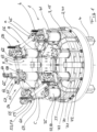
- the radial press 1 illustrated in the drawing and designed for operation with a vertical press axis X comprises a first, lower ring structure 2 and a second, upper ring structure 3. Both ring structures 2, 3 extend around the press axis X.
- the lower ring structure 2 is designed as a stationary ring structure and is supported on the support 4
- the second, upper ring structure 3 can be raised and lowered by means of a drive system - eight actuators C arranged around the press axis and comprising parallel oriented actuators C, ie the distance between the upper ring structure 3 and the lower ring structure 2 can be reduced by means of the drive system enlarge.
- the lower ring structure has a pot-like basic shape (opened in the center!) in that it has a base ring 6 and a substantially cylindrical wall 7 projecting from it; it is dimensioned so that the lowered upper ring structure 3 fits into the lower one Ring structure 2 occurs that it and the cylindrical wall 7 of the lower ring structure 2 overlap each other.
- the radial press comprises eight pressed bodies 8 which are arranged evenly around the press axis support flat support surface 12.
- the upper support surfaces 11 are each designed on the surface of a replaceable upper sliding plate 13, and the lower support surfaces 12 are each designed on the surface of a replaceable lower sliding plate 14. While the lower support surfaces 12 (and the associated lower counter surfaces 10) are perpendicular to the press axis X stand, the upper support surfaces 11 (as well as the associated upper counter surfaces 9) are oriented inclined to the press axis X.
- the upper support surfaces 11 represent “control surfaces” via which an axial movement of the upper ring structure 3 is converted into a radial movement of the pressed bodies 8.
- the upper ring structure 3 thus forms a “control ring” 15.
- the pressed bodies 8 include base jaws 16, on which the upper and lower counter surfaces 9 and 10 are designed, and press jaws 17 that can be interchangeably attached to the base jaws 16.
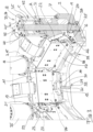
- Each of the base jaws 16 - the extent of which is parallel to the press axis X is approximately twice as large as transversely this - is guided on the upper ring structure 3 via an upper positive guide 18 and on the lower ring structure 2 via a lower positive guide 19 in such a way that it is (at least essentially) free of play on the two assigned support surfaces 11 or 12 is held, that is, it cannot be withdrawn from them.
- the upper positive guide 18 comprises two guide grooves 20, which are incorporated laterally on the relevant base jaw 16 and extend parallel to the upper counter surface 9, and guide bodies 21 which engage in this and are arranged on the upper ring structure 3 in the form of roller arrangements attached to an (upper) roller carrier 22 23.
- the individual rollers are each mounted on a bolt designed as an adjusting eccentric.
- sliding plates 27 which define a support surface are attached to the upper roller carriers 22, on which the base jaws 16 are supported via assigned counter surfaces 28.
- At least one part of the pressed bodies 8 is assigned a displacement measuring device 29 (with a measuring direction parallel to the lower positive guides 19, i.e. radially oriented), by means of which the relative position of the relevant base jaw 16 in relation to the lower ring structure 2 can be detected.
- the distance measuring device 29 in question comprises a pin 30 connected to the base jaw 16 in question and projecting downwards therefrom with a sensor 31 arranged at the end thereof, which cooperates with an associated, radially extending measuring ruler 32 fixed to the lower ring structure 2.
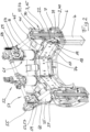
- the drive system used for the relative movement of the two ring structures 2 and 3 with respect to one another is designed hydraulically; it includes - as actuators C - eight hydraulic cylinder-piston units 33 oriented parallel to the press axis
- the hydraulic cylinder-piston units 33 - each arranged in a gap with the pressed bodies 8 - are designed as synchronous cylinders 34.
- the cylinder 35 is firmly connected to the upper ring structure 3 (control ring 15) via an assigned flange 37 formed on the cylinder base 36.
- the lower end 38 of the respective piston rod 39 extending through the cylinder 35 is, in contrast, firmly connected to the lower ring structure 2 (“support ring” 40).
- each hydraulic cylinder-piston unit 33 within the respective cylinder 35, which is closed at the top by a pierced cover 41, two hydraulic working spaces A and B are defined, which are delimited from one another by the piston 42 which is firmly connected to the piston rod 39. These are supplied through the pierced piston rod 39.
- a valve unit 45 is constructed on the upper end 43 of the piston rod 39 passing through the opening 44 of the cover 41 - or possibly on a mounting plate (see below) connected to it.
- the two are integrated into the respective valve unit 45 via an electric actuator 48
- Operable switching valves 49 allow switching between, on the one hand, a fluidic communication of the two work spaces A and B with the pressure supply unit (via a passage connection of the connection a to the connection c and the connection b to the connection d) and, on the other hand, a direct hydraulic short circuit both work spaces A and B via an internal bypass 50 that fluidly connects the connections c and d.
- the two work spaces A and B are shut off from the pressure supply unit by means of the switching valves 49.
- Said bypasses 50 are opened when a rapid adjustment of the two ring structures 2 and 3 relative to one another takes place by means of a rapid adjustment drive 51.
- This is designed electromechanically and includes a drive unit 52, four adjusters 53 and a drive train 56 which connects the drive unit 52 to the four adjusters 53 and has shafts 54 and deflection gear 55.
- Each of the four adjusters 53 (designed as a rack drive 57) is - between the cylinder 35 and the piston rod 39 acting - assigned to a hydraulic cylinder-piston unit 33.
- a toothed wheel 58 which is fixed on the cover 41 of the respectively assigned hydraulic cylinder-piston unit 33 engages with a gear wheel which is rotatably mounted in a toothed drive housing 59.
- the toothed drive housing 59 is constructed on a mounting plate 60, which in turn is firmly connected to the end section of the piston rod 39 of the relevant hydraulic cylinder-piston unit 33 protruding from the cover 41.
- Position measuring systems 61 are provided, each with a measuring ruler 62 fixed to the cover 41 of the associated hydraulic cylinder-piston unit 33 and a sensor 63 fixed to the relevant mounting plate 60.
- the drive unit 52 which is also connected (at least indirectly) in a fixed position to the piston rod 39 of the relevant hydraulic cylinder-piston unit 33 and is in particular built on the valve unit 45 assigned to it, comprises a servomotor 64 with a flanged, self-locking planetary gear 65, an electromechanical separating clutch 66, one of the Manual operation input 67 and a transfer case 68 with two outputs 69, to which assigned shafts 54 of the drive train 56 are connected.
- the unit consisting of the upper ring structure 3 and the eight cylinders 35 of the hydraulic cylinder-piston units 33 connected to it is supported on the lower ring structure 2 via spring elements 70 at least to the extent of a substantial part of its mass.
- gas springs 71 extend between a lower articulation point 72 assigned to the lower ring structure 2 and an upper articulation point 73 assigned to the cover 41 of a hydraulic cylinder-piston unit 33.
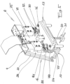
- the locks each comprise a clamping unit 76 attached to the base jaw base body 75 with a pivotally driven claw, which pulls the respective pressing jaw 17 - resting on the reinforcement rail 77 of the base jaw base body 75 - radially outwards into its locking position defined by the stops 78 .
- the locking comprises two hydraulic cylinders 79 arranged in pairs on the base jaw base body 75 with locking heads 80 attached to the respective piston rod, which press the relevant pressing jaw 17 into the assigned receptacle of the base jaw base body 75.
- a mechanical spring 81 supports the respective hydraulic cylinder 79 and ensures that the relevant pressing jaw 17 is held on the respective base jaw 16 even without external energy, that is, it does not tip over due to its own weight.
- the position of the locking heads 80 is detected by sensors 82, which are attached to the base jaw base body 75 via angles 83.
Landscapes
- Engineering & Computer Science (AREA)
- Mechanical Engineering (AREA)
- Press Drives And Press Lines (AREA)
Claims (15)
- Presse radiale (1), pourvue d'une première et d'une deuxième structures annulaires (2 ; 3) s'étendant autour d'un axe de presse (X) et de plusieurs corps de pression (8) placées entre celles-ci autour de l'axe de presse (X), s'appuyant de manière déplaçable sur des surfaces d'appui (11 ; 12) associées aux structures annulaires, l'écart axial mutuel entre les deux structures annulaires (2, 3) étant variable à l'aide d'un système d'entraînement, lequel comprend une pluralité d'actionneurs (C) orientés à la parallèle par rapport à l'axe de presse (X) et placés en distribution autour de celui-ci, dont chaque fois un premier composant est couplé avec une première des deux structures annulaires et un deuxième composant activement mobile par rapport au premier composant est couplé avec la deuxième structure annulaire, et par ailleurs au moins les surfaces d'appui (11) associées aux deux structures annulaires (3) étant orientées en inclinaison vers l'axe de presse (X) et les corps de pression (8) étant en guidage forcé par rapport aux deux structures annulaires (2, 3),
caractérisée
en ce que le guidage forcé (18, 19) s'effectue par l'intermédiaire d'appairages respectivement associés par l'intermédiaire des corps de pression (8) et de la structure annulaire (2, 3) concernée de rainures de guidage (20, 24) réalisées sur les corps de pression (8) et de corps de guidage (21) s'engageant dans celles-ci, comprenant des galets de guidage (23, 26). - Presse radiale selon la revendication 1, caractérisée en ce que les galets de guidage (23, 26) sont logés chacun sur un boulon réalisé sous la forme d'un excentrique d'ajustage.
- Presse radiale selon la revendication 1 ou la revendication 2, caractérisée en ce que les corps de pression (8) comprennent des mâchoires de base (16) et des mâchoires de pression (17) susceptibles d'être fixées sur celles-ci de manière interchangeable.
- Presse radiale selon la revendication 3, caractérisée en ce que l'extension des mâchoires de base à la parallèle de l'axe de presse (X) correspond au moins au double de celle à la transversale de celle-ci et / ou en ce qu'entre les mâchoires de base (16) et les mâchoires de pression (17) agit un système de verrouillage à actionnement hydraulique.
- Presse radiale selon l'une quelconque des revendications 1 à 4, caractérisée en ce que seules les surfaces d'appui (11) associées à l'une des deux structures annulaires (2, 3) sont inclinées vers l'axe de presse (X), en revanche, les surfaces d'appui (12) associées à l'autre structure annulaire (2) sont orientées à la perpendiculaire de l'axe de presse (X).
- Presse radiale selon la revendication 5, caractérisée en ce que la structure annulaire (2) comportant des surfaces d'appui (12) orientées à la perpendiculaire de l'axe de presse (X) est réalisée sous la forme d'une structure annulaire (40) stationnaire.
- Presse radiale selon la revendication 6, caractérisée en ce qu'entre la structure annulaire (40) stationnaire et au moins l'un des corps de pression (8), un dispositif de mesure de déplacement (29) agit avec une direction de mesure à orientation radiale.
- Presse radiale selon l'une quelconque des revendications 1 à 7, caractérisée en ce que l'axe de presse (X) est orienté à la verticale, l'une des structures annulaires constituant une structure annulaire (2) inférieure et l'autre structure annulaire constituant une structure annulaire (3) supérieure, de préférence, la structure annulaire (2) inférieure s'appuyant par l'intermédiaire d'une structure porteuse (4) sur le sol, avec un écart par rapport à celui-ci.
- Presse radiale selon la revendication 8, caractérisée en ce que la structure annulaire (3) supérieure s'appuie au moins sur la périphérie d'une majeure partie de sa propre masse, ainsi que de celle des composants des actionneurs qui lui sont associés par l'intermédiaire d'éléments à ressort (70) sur la structure annulaire (2) inférieure, des éléments à ressort (70) réalisés de préférence sous la forme de ressorts à gaz (71) agissant sur des composants des actionneurs associés entre la structure annulaire (2) inférieure et la structure annulaire (3) supérieure.
- Presse radiale selon l'une quelconque des revendications 1 à 9, caractérisée en ce qu'il est prévu un système d'entraînement hydraulique, en ce que les actionneurs (C) sont réalisés sous la forme d'unités piston / cylindre (33) hydrauliques, dont chaque fois le cylindre (35) constitue le premier composant et la tige de piston (39) constitue le deuxième composant de l'actionneur (C) concerné.
- Presse radiale selon la revendication 10, caractérisée en ce que les unités piston / cylindre (33) sont réalisées sous la forme de cylindres synchrones (34), de préférence à chaque cylindre synchrone (34) étant associée une unité de soupapes (45) permettant un court-circuit hydraulique direct des deux chambres de travail (A, B) du cylindre synchrone (34) concerné.
- Presse radiale selon la revendication 11, caractérisée en ce que les unités de soupapes (45) sont placées chacune du côté extrémité sur la tige de piston (39) associée, comportant des canalisations d'alimentation (46, 47).
- Presse radiale selon l'une quelconque des revendications 1 à 12, caractérisée en ce qu'il est prévu un entraînement d'ajustement (51) grande vitesse, comprenant plusieurs organes d'ajustage (53).
- Presse radiale selon la revendication 13, caractérisée en ce que l'entraînement d'ajustement (51) grande vitesse comprend un servomoteur (64) commun, agissant sur tous les organes d'ajustage (53).
- Presse radiale selon la revendication 13 ou la revendication 14, caractérisée en ce que les organes d'ajustage (53) agissent chacun entre les composants d'un actionneur activement ajustables les uns par rapport aux autres, notamment entre le cylindre (35) et la tige de piston (39) d'une unité piston / cylindre (33) hydraulique.
Applications Claiming Priority (2)
| Application Number | Priority Date | Filing Date | Title |
|---|---|---|---|
| DE102020121142.2A DE102020121142B4 (de) | 2020-08-11 | 2020-08-11 | Radialpresse |
| PCT/EP2021/070350 WO2022033819A1 (fr) | 2020-08-11 | 2021-07-21 | Presse radiale |
Publications (2)
| Publication Number | Publication Date |
|---|---|
| EP4132777A1 EP4132777A1 (fr) | 2023-02-15 |
| EP4132777B1 true EP4132777B1 (fr) | 2023-10-18 |
Family
ID=77104083
Family Applications (1)
| Application Number | Title | Priority Date | Filing Date |
|---|---|---|---|
| EP21746743.0A Active EP4132777B1 (fr) | 2020-08-11 | 2021-07-21 | Presse radiale |
Country Status (6)
| Country | Link |
|---|---|
| US (1) | US12251902B2 (fr) |
| EP (1) | EP4132777B1 (fr) |
| CN (1) | CN115916517B (fr) |
| DE (1) | DE102020121142B4 (fr) |
| FI (1) | FI4132777T3 (fr) |
| WO (1) | WO2022033819A1 (fr) |
Family Cites Families (17)
| Publication number | Priority date | Publication date | Assignee | Title |
|---|---|---|---|---|
| FR2341093A1 (fr) | 1976-02-13 | 1977-09-09 | Anoflex Flexibles | Machine a sertir des embouts sur des tuyauteries souples |
| DE2844475C2 (de) * | 1978-10-12 | 1983-09-29 | Peter Ing.(grad.) 6380 Bad Homburg Schröck | Radialpresse für Werkstücke mit zylindrischer Außenfläche |
| US4550587A (en) | 1983-12-15 | 1985-11-05 | The Goodyear Tire & Rubber Company | Heavy duty hose crimper |
| DE3512241A1 (de) | 1985-04-03 | 1986-10-16 | Peter Dipl Ing Schroeck | Radialpresse |
| DE3611253A1 (de) | 1986-04-04 | 1987-10-08 | Peter Dipl Ing Schroeck | Radialpresse |
| JP3281175B2 (ja) | 1994-04-18 | 2002-05-13 | 株式会社東芝 | プレス成形装置 |
| DE19861171B4 (de) * | 1998-04-22 | 2005-09-22 | Uniflex-Hydraulik Gmbh | Radialpresse |
| DE20017791U1 (de) | 2000-10-17 | 2000-12-28 | Uniflex-Hydraulik GmbH, 61184 Karben | Preßbackensatz für eine Radialpresse |
| DE10149924A1 (de) | 2001-10-10 | 2003-04-30 | Uniflex Hydraulik Gmbh | Radialpresse |
| DE102005041487A1 (de) | 2005-08-30 | 2007-04-05 | Ekf Werkzeug Und Maschinenbau Gmbh | Radialpresse |
| DE102006036654B4 (de) | 2006-08-03 | 2008-12-04 | Harald Weigelt | Keiltrieb mit Zwangsrückholeinrichtung |
| DE102009057726A1 (de) * | 2009-12-10 | 2011-06-16 | Uniflex-Hydraulik Gmbh | Radialpresse |
| PL2420332T3 (pl) * | 2010-08-20 | 2013-05-31 | Op Srl | Chwytak do trzymania narzędzi prasy promieniowej |
| US9821363B2 (en) * | 2015-09-30 | 2017-11-21 | Ed Goff | Radial compression device with constrained dies |
| DE102016102275A1 (de) * | 2016-02-10 | 2017-08-10 | Uniflex-Hydraulik Gmbh | Radialpresse |
| DE102016106650B4 (de) * | 2016-04-12 | 2021-09-16 | Uniflex-Hydraulik Gmbh | Radialpresse |
| DE102017119403A1 (de) | 2017-08-24 | 2019-02-28 | Uniflex-Hydraulik Gmbh | Radialpressensystem |
-
2020
- 2020-08-11 DE DE102020121142.2A patent/DE102020121142B4/de not_active Expired - Fee Related
-
2021
- 2021-07-21 CN CN202180043048.9A patent/CN115916517B/zh active Active
- 2021-07-21 FI FIEP21746743.0T patent/FI4132777T3/fi active
- 2021-07-21 WO PCT/EP2021/070350 patent/WO2022033819A1/fr not_active Ceased
- 2021-07-21 EP EP21746743.0A patent/EP4132777B1/fr active Active
-
2022
- 2022-12-08 US US18/077,885 patent/US12251902B2/en active Active
Also Published As
| Publication number | Publication date |
|---|---|
| CN115916517B (zh) | 2024-07-02 |
| FI4132777T3 (fi) | 2024-01-09 |
| WO2022033819A1 (fr) | 2022-02-17 |
| DE102020121142A1 (de) | 2022-02-17 |
| US12251902B2 (en) | 2025-03-18 |
| US20230114893A1 (en) | 2023-04-13 |
| CN115916517A (zh) | 2023-04-04 |
| DE102020121142B4 (de) | 2022-03-10 |
| EP4132777A1 (fr) | 2023-02-15 |
Similar Documents
| Publication | Publication Date | Title |
|---|---|---|
| EP2509725B1 (fr) | Presse radiale | |
| DE102012209077B4 (de) | Spanneinrichtung zum Einspannen eines stabartigen Werkstücks und Werkzeugmaschine damit | |
| EP2512791A2 (fr) | Dispositif d'entraînement pour une presse de pliage | |
| DE102007051894A1 (de) | Freigabemechanismus und mit diesem versehenen Richtvorrichtung | |
| DE102023123181A1 (de) | Vorrichtung zum Herstellen von Formlingen, insbesondere Steinformlinge für Mauerwerksteine und Verfahren zum Ändern eines Formats von herzustellenden Formlingen | |
| AT509907B1 (de) | Schliesseinheit für eine spritzgiessmaschine | |
| EP4132777B1 (fr) | Presse radiale | |
| EP1252010A1 (fr) | Presse | |
| EP4135973B1 (fr) | Presse radiale | |
| DE102004006126A1 (de) | Presse mit verriegeltem Stößel | |
| AT507110A1 (de) | Presse zum umformen von material | |
| EP0051121B1 (fr) | Machine de fluotournage | |
| WO2005021253A2 (fr) | Presse hydraulique | |
| DE102006019207B4 (de) | Antriebssystem einer Mehrstößel-Umformpresse | |
| WO2010094383A2 (fr) | Dispositif de réalisation de pièces moulées | |
| EP0002032B1 (fr) | Procédé et dispositif de fabrication de poulies multigorges | |
| EP0125540B1 (fr) | Dispositif de fabrication de tubes pourvus de trous dans leur paroi | |
| WO2014001198A1 (fr) | Machine de forage profond, adaptateur et procédé de forage profond | |
| EP3024646B1 (fr) | Module de force et système de pressage modulaire | |
| EP0268681A1 (fr) | Presse a vis a double effet | |
| DE19607257C2 (de) | Hydraulische Blechformpresse | |
| DE19809371A1 (de) | Kupplung zur Verbindung von Werkstückgreifern mit einer Handhabungseinrichtung | |
| EP1344585B1 (fr) | Dispositif d'emboutissage profond hydroélastique | |
| DE4444497A1 (de) | Schmiedemaschine | |
| EP0653258A1 (fr) | Machine à forger |
Legal Events
| Date | Code | Title | Description |
|---|---|---|---|
| STAA | Information on the status of an ep patent application or granted ep patent |
Free format text: STATUS: UNKNOWN |
|
| STAA | Information on the status of an ep patent application or granted ep patent |
Free format text: STATUS: THE INTERNATIONAL PUBLICATION HAS BEEN MADE |
|
| PUAI | Public reference made under article 153(3) epc to a published international application that has entered the european phase |
Free format text: ORIGINAL CODE: 0009012 |
|
| STAA | Information on the status of an ep patent application or granted ep patent |
Free format text: STATUS: REQUEST FOR EXAMINATION WAS MADE |
|
| 17P | Request for examination filed |
Effective date: 20221110 |
|
| AK | Designated contracting states |
Kind code of ref document: A1 Designated state(s): AL AT BE BG CH CY CZ DE DK EE ES FI FR GB GR HR HU IE IS IT LI LT LU LV MC MK MT NL NO PL PT RO RS SE SI SK SM TR |
|
| GRAP | Despatch of communication of intention to grant a patent |
Free format text: ORIGINAL CODE: EPIDOSNIGR1 |
|
| STAA | Information on the status of an ep patent application or granted ep patent |
Free format text: STATUS: GRANT OF PATENT IS INTENDED |
|
| INTG | Intention to grant announced |
Effective date: 20230512 |
|
| P01 | Opt-out of the competence of the unified patent court (upc) registered |
Effective date: 20230529 |
|
| GRAS | Grant fee paid |
Free format text: ORIGINAL CODE: EPIDOSNIGR3 |
|
| GRAA | (expected) grant |
Free format text: ORIGINAL CODE: 0009210 |
|
| STAA | Information on the status of an ep patent application or granted ep patent |
Free format text: STATUS: THE PATENT HAS BEEN GRANTED |
|
| AK | Designated contracting states |
Kind code of ref document: B1 Designated state(s): AL AT BE BG CH CY CZ DE DK EE ES FI FR GB GR HR HU IE IS IT LI LT LU LV MC MK MT NL NO PL PT RO RS SE SI SK SM TR |
|
| DAV | Request for validation of the european patent (deleted) | ||
| DAX | Request for extension of the european patent (deleted) | ||
| REG | Reference to a national code |
Ref country code: GB Ref legal event code: FG4D Free format text: NOT ENGLISH |
|
| REG | Reference to a national code |
Ref country code: CH Ref legal event code: EP |
|
| REG | Reference to a national code |
Ref country code: DE Ref legal event code: R096 Ref document number: 502021001751 Country of ref document: DE |
|
| REG | Reference to a national code |
Ref country code: IE Ref legal event code: FG4D Free format text: LANGUAGE OF EP DOCUMENT: GERMAN |
|
| REG | Reference to a national code |
Ref country code: FI Ref legal event code: FGE |
|
| REG | Reference to a national code |
Ref country code: LT Ref legal event code: MG9D |
|
| REG | Reference to a national code |
Ref country code: NL Ref legal event code: MP Effective date: 20231018 |
|
| PG25 | Lapsed in a contracting state [announced via postgrant information from national office to epo] |
Ref country code: NL Free format text: LAPSE BECAUSE OF FAILURE TO SUBMIT A TRANSLATION OF THE DESCRIPTION OR TO PAY THE FEE WITHIN THE PRESCRIBED TIME-LIMIT Effective date: 20231018 |
|
| PG25 | Lapsed in a contracting state [announced via postgrant information from national office to epo] |
Ref country code: GR Free format text: LAPSE BECAUSE OF FAILURE TO SUBMIT A TRANSLATION OF THE DESCRIPTION OR TO PAY THE FEE WITHIN THE PRESCRIBED TIME-LIMIT Effective date: 20240119 |
|
| PG25 | Lapsed in a contracting state [announced via postgrant information from national office to epo] |
Ref country code: IS Free format text: LAPSE BECAUSE OF FAILURE TO SUBMIT A TRANSLATION OF THE DESCRIPTION OR TO PAY THE FEE WITHIN THE PRESCRIBED TIME-LIMIT Effective date: 20240218 |
|
| PG25 | Lapsed in a contracting state [announced via postgrant information from national office to epo] |
Ref country code: LT Free format text: LAPSE BECAUSE OF FAILURE TO SUBMIT A TRANSLATION OF THE DESCRIPTION OR TO PAY THE FEE WITHIN THE PRESCRIBED TIME-LIMIT Effective date: 20231018 |
|
| PG25 | Lapsed in a contracting state [announced via postgrant information from national office to epo] |
Ref country code: ES Free format text: LAPSE BECAUSE OF FAILURE TO SUBMIT A TRANSLATION OF THE DESCRIPTION OR TO PAY THE FEE WITHIN THE PRESCRIBED TIME-LIMIT Effective date: 20231018 |
|
| PG25 | Lapsed in a contracting state [announced via postgrant information from national office to epo] |
Ref country code: LT Free format text: LAPSE BECAUSE OF FAILURE TO SUBMIT A TRANSLATION OF THE DESCRIPTION OR TO PAY THE FEE WITHIN THE PRESCRIBED TIME-LIMIT Effective date: 20231018 Ref country code: IS Free format text: LAPSE BECAUSE OF FAILURE TO SUBMIT A TRANSLATION OF THE DESCRIPTION OR TO PAY THE FEE WITHIN THE PRESCRIBED TIME-LIMIT Effective date: 20240218 Ref country code: GR Free format text: LAPSE BECAUSE OF FAILURE TO SUBMIT A TRANSLATION OF THE DESCRIPTION OR TO PAY THE FEE WITHIN THE PRESCRIBED TIME-LIMIT Effective date: 20240119 Ref country code: ES Free format text: LAPSE BECAUSE OF FAILURE TO SUBMIT A TRANSLATION OF THE DESCRIPTION OR TO PAY THE FEE WITHIN THE PRESCRIBED TIME-LIMIT Effective date: 20231018 Ref country code: BG Free format text: LAPSE BECAUSE OF FAILURE TO SUBMIT A TRANSLATION OF THE DESCRIPTION OR TO PAY THE FEE WITHIN THE PRESCRIBED TIME-LIMIT Effective date: 20240118 Ref country code: PT Free format text: LAPSE BECAUSE OF FAILURE TO SUBMIT A TRANSLATION OF THE DESCRIPTION OR TO PAY THE FEE WITHIN THE PRESCRIBED TIME-LIMIT Effective date: 20240219 |
|
| PG25 | Lapsed in a contracting state [announced via postgrant information from national office to epo] |
Ref country code: SE Free format text: LAPSE BECAUSE OF FAILURE TO SUBMIT A TRANSLATION OF THE DESCRIPTION OR TO PAY THE FEE WITHIN THE PRESCRIBED TIME-LIMIT Effective date: 20231018 Ref country code: RS Free format text: LAPSE BECAUSE OF FAILURE TO SUBMIT A TRANSLATION OF THE DESCRIPTION OR TO PAY THE FEE WITHIN THE PRESCRIBED TIME-LIMIT Effective date: 20231018 Ref country code: PL Free format text: LAPSE BECAUSE OF FAILURE TO SUBMIT A TRANSLATION OF THE DESCRIPTION OR TO PAY THE FEE WITHIN THE PRESCRIBED TIME-LIMIT Effective date: 20231018 Ref country code: NO Free format text: LAPSE BECAUSE OF FAILURE TO SUBMIT A TRANSLATION OF THE DESCRIPTION OR TO PAY THE FEE WITHIN THE PRESCRIBED TIME-LIMIT Effective date: 20240118 Ref country code: LV Free format text: LAPSE BECAUSE OF FAILURE TO SUBMIT A TRANSLATION OF THE DESCRIPTION OR TO PAY THE FEE WITHIN THE PRESCRIBED TIME-LIMIT Effective date: 20231018 Ref country code: HR Free format text: LAPSE BECAUSE OF FAILURE TO SUBMIT A TRANSLATION OF THE DESCRIPTION OR TO PAY THE FEE WITHIN THE PRESCRIBED TIME-LIMIT Effective date: 20231018 |
|
| PG25 | Lapsed in a contracting state [announced via postgrant information from national office to epo] |
Ref country code: DK Free format text: LAPSE BECAUSE OF FAILURE TO SUBMIT A TRANSLATION OF THE DESCRIPTION OR TO PAY THE FEE WITHIN THE PRESCRIBED TIME-LIMIT Effective date: 20231018 |
|
| REG | Reference to a national code |
Ref country code: DE Ref legal event code: R097 Ref document number: 502021001751 Country of ref document: DE |
|
| PG25 | Lapsed in a contracting state [announced via postgrant information from national office to epo] |
Ref country code: SK Free format text: LAPSE BECAUSE OF FAILURE TO SUBMIT A TRANSLATION OF THE DESCRIPTION OR TO PAY THE FEE WITHIN THE PRESCRIBED TIME-LIMIT Effective date: 20231018 |
|
| PG25 | Lapsed in a contracting state [announced via postgrant information from national office to epo] |
Ref country code: SM Free format text: LAPSE BECAUSE OF FAILURE TO SUBMIT A TRANSLATION OF THE DESCRIPTION OR TO PAY THE FEE WITHIN THE PRESCRIBED TIME-LIMIT Effective date: 20231018 Ref country code: SK Free format text: LAPSE BECAUSE OF FAILURE TO SUBMIT A TRANSLATION OF THE DESCRIPTION OR TO PAY THE FEE WITHIN THE PRESCRIBED TIME-LIMIT Effective date: 20231018 Ref country code: RO Free format text: LAPSE BECAUSE OF FAILURE TO SUBMIT A TRANSLATION OF THE DESCRIPTION OR TO PAY THE FEE WITHIN THE PRESCRIBED TIME-LIMIT Effective date: 20231018 Ref country code: EE Free format text: LAPSE BECAUSE OF FAILURE TO SUBMIT A TRANSLATION OF THE DESCRIPTION OR TO PAY THE FEE WITHIN THE PRESCRIBED TIME-LIMIT Effective date: 20231018 Ref country code: DK Free format text: LAPSE BECAUSE OF FAILURE TO SUBMIT A TRANSLATION OF THE DESCRIPTION OR TO PAY THE FEE WITHIN THE PRESCRIBED TIME-LIMIT Effective date: 20231018 |
|
| PLBE | No opposition filed within time limit |
Free format text: ORIGINAL CODE: 0009261 |
|
| STAA | Information on the status of an ep patent application or granted ep patent |
Free format text: STATUS: NO OPPOSITION FILED WITHIN TIME LIMIT |
|
| 26N | No opposition filed |
Effective date: 20240719 |
|
| PG25 | Lapsed in a contracting state [announced via postgrant information from national office to epo] |
Ref country code: SI Free format text: LAPSE BECAUSE OF FAILURE TO SUBMIT A TRANSLATION OF THE DESCRIPTION OR TO PAY THE FEE WITHIN THE PRESCRIBED TIME-LIMIT Effective date: 20231018 |
|
| PG25 | Lapsed in a contracting state [announced via postgrant information from national office to epo] |
Ref country code: SI Free format text: LAPSE BECAUSE OF FAILURE TO SUBMIT A TRANSLATION OF THE DESCRIPTION OR TO PAY THE FEE WITHIN THE PRESCRIBED TIME-LIMIT Effective date: 20231018 |
|
| PG25 | Lapsed in a contracting state [announced via postgrant information from national office to epo] |
Ref country code: MC Free format text: LAPSE BECAUSE OF FAILURE TO SUBMIT A TRANSLATION OF THE DESCRIPTION OR TO PAY THE FEE WITHIN THE PRESCRIBED TIME-LIMIT Effective date: 20231018 |
|
| REG | Reference to a national code |
Ref country code: CH Ref legal event code: PL |
|
| PG25 | Lapsed in a contracting state [announced via postgrant information from national office to epo] |
Ref country code: LU Free format text: LAPSE BECAUSE OF NON-PAYMENT OF DUE FEES Effective date: 20240721 |
|
| PG25 | Lapsed in a contracting state [announced via postgrant information from national office to epo] |
Ref country code: LU Free format text: LAPSE BECAUSE OF NON-PAYMENT OF DUE FEES Effective date: 20240721 |
|
| PG25 | Lapsed in a contracting state [announced via postgrant information from national office to epo] |
Ref country code: CH Free format text: LAPSE BECAUSE OF NON-PAYMENT OF DUE FEES Effective date: 20240731 Ref country code: BE Free format text: LAPSE BECAUSE OF NON-PAYMENT OF DUE FEES Effective date: 20240731 |
|
| PG25 | Lapsed in a contracting state [announced via postgrant information from national office to epo] |
Ref country code: FR Free format text: LAPSE BECAUSE OF NON-PAYMENT OF DUE FEES Effective date: 20240731 |
|
| REG | Reference to a national code |
Ref country code: BE Ref legal event code: MM Effective date: 20240731 |
|
| PG25 | Lapsed in a contracting state [announced via postgrant information from national office to epo] |
Ref country code: IE Free format text: LAPSE BECAUSE OF NON-PAYMENT OF DUE FEES Effective date: 20240721 |
|
| PGFP | Annual fee paid to national office [announced via postgrant information from national office to epo] |
Ref country code: FI Payment date: 20250722 Year of fee payment: 5 |
|
| PGFP | Annual fee paid to national office [announced via postgrant information from national office to epo] |
Ref country code: DE Payment date: 20250929 Year of fee payment: 5 |
|
| PGFP | Annual fee paid to national office [announced via postgrant information from national office to epo] |
Ref country code: IT Payment date: 20250731 Year of fee payment: 5 |
|
| PGFP | Annual fee paid to national office [announced via postgrant information from national office to epo] |
Ref country code: AT Payment date: 20251020 Year of fee payment: 5 |
|
| PGFP | Annual fee paid to national office [announced via postgrant information from national office to epo] |
Ref country code: CZ Payment date: 20250710 Year of fee payment: 5 |
|
| PG25 | Lapsed in a contracting state [announced via postgrant information from national office to epo] |
Ref country code: CY Free format text: LAPSE BECAUSE OF FAILURE TO SUBMIT A TRANSLATION OF THE DESCRIPTION OR TO PAY THE FEE WITHIN THE PRESCRIBED TIME-LIMIT; INVALID AB INITIO Effective date: 20210721 |
|
| PG25 | Lapsed in a contracting state [announced via postgrant information from national office to epo] |
Ref country code: HU Free format text: LAPSE BECAUSE OF FAILURE TO SUBMIT A TRANSLATION OF THE DESCRIPTION OR TO PAY THE FEE WITHIN THE PRESCRIBED TIME-LIMIT; INVALID AB INITIO Effective date: 20210721 |
|
| GBPC | Gb: european patent ceased through non-payment of renewal fee |
Effective date: 20250721 |
|
| PG25 | Lapsed in a contracting state [announced via postgrant information from national office to epo] |
Ref country code: GB Free format text: LAPSE BECAUSE OF NON-PAYMENT OF DUE FEES Effective date: 20250721 |