EP4132817B1 - System aus schleppbaren trägern - Google Patents
System aus schleppbaren trägern Download PDFInfo
- Publication number
- EP4132817B1 EP4132817B1 EP21730679.4A EP21730679A EP4132817B1 EP 4132817 B1 EP4132817 B1 EP 4132817B1 EP 21730679 A EP21730679 A EP 21730679A EP 4132817 B1 EP4132817 B1 EP 4132817B1
- Authority
- EP
- European Patent Office
- Prior art keywords
- jaws
- support
- notches
- supports
- towable
- Prior art date
- Legal status (The legal status is an assumption and is not a legal conclusion. Google has not performed a legal analysis and makes no representation as to the accuracy of the status listed.)
- Active
Links
Images




Classifications
-
- B—PERFORMING OPERATIONS; TRANSPORTING
- B60—VEHICLES IN GENERAL
- B60P—VEHICLES ADAPTED FOR LOAD TRANSPORTATION OR TO TRANSPORT, TO CARRY, OR TO COMPRISE SPECIAL LOADS OR OBJECTS
- B60P3/00—Vehicles adapted to transport, to carry or to comprise special loads or objects
-
- B—PERFORMING OPERATIONS; TRANSPORTING
- B60—VEHICLES IN GENERAL
- B60P—VEHICLES ADAPTED FOR LOAD TRANSPORTATION OR TO TRANSPORT, TO CARRY, OR TO COMPRISE SPECIAL LOADS OR OBJECTS
- B60P7/00—Securing or covering of load on vehicles
- B60P7/06—Securing of load
- B60P7/135—Securing or supporting by load bracing means
- B60P7/15—Securing or supporting by load bracing means the load bracing means comprising a movable bar
Definitions
- the present invention relates to a towable support system comprising a plurality of supports, each of the supports comprising a coupling element with a towing vehicle to enable the latter to move the support, the system also comprising at least one motorized towing vehicle comprising an assembly tightening of the coupling element.
- Some solutions require a suitable vehicle to lift the shelf, as for example in the document WO2019009729 , which describes a robotic vehicle and its use for moving a goods carrier, which is for example loaded with goods, this vehicle can be used in an empty position and a loaded position.
- the vehicle is positioned under the shelf to be moved.
- a means of lifting the vehicle allows the shelf to be lifted to clear the wheels off the ground and thus allow movement without constraint.
- the shelf is placed back on the ground on its wheels or feet and the vehicle moves on to another task.
- WO2008085639 describes an apparatus for transporting inventory items including a housing, a drive module, a docking module, a lift shaft and a rotation module.
- the drive module is capable of propelling the device in at least a first direction.
- a docking head is capable of mating to or supporting an inventory rack.
- the rotation module is capable of inducing rotation in the housing relative to the lift shaft.
- the lift shaft connects to the docking head and is capable of lifting the docking head when the housing is rotated relative to the lift shaft.
- the document WO2006044108 describes an inventory transportation system including an inventory carrier and a mobile drive unit.
- the inventory rack includes a frame capable of storing inventory items and a docking plate capable of receiving a docking head from below.
- the mobile drive unit includes a docking head capable of coupling to the docking plate and a drive module capable of propelling the mobile drive unit.
- the movable drive unit is further capable of moving the inventory carrier when the docking head is coupled to the inventory carrier.
- the coupling mode making it possible to connect the vehicle and the support to be towed requires perfect alignment between vehicle rods intended for insertion into hollow cylinders arranged under the support. Such alignment to ensure coupling is difficult to achieve, involves complex guiding means, and has a level of reliability that can be improved.
- the invention provides different technical means.
- a first object of the invention consists of providing a means of securing between a support such as a shelf mounted on casters and a tractor robot making it possible to achieve safe and reliable securing.
- Another object of the invention consists of providing a means of securing between a support such as a shelf mounted on casters and a tractor robot making it possible to prevent securing when certain predefined safety conditions are not respected.
- Another object of the invention consists of providing a means of securing between a support such as a shelf mounted on casters and a robot tractor making it possible to operate in automatic mode reliably, with a high level of safety.
- Yet another object of the invention consists of providing a means of securing between a support such as a shelf mounted on casters and a robot tractor making it possible to travel at high speeds in complete safety.
- Such an architecture ensures safe and reliable coupling between a towing vehicle and a compatible support.
- the double anchoring of the jaws in the notches of the drawbar provides a precise mechanical connection ensuring efficient transmission of forces to pull or push or rotate the support.
- the axial space between the anchors along the drawbar allows excellent transmission of torque forces to rotate the support.
- the vehicle can fit under the support from the front or rear, or from either side. The position of the jaws, which is barely or not accessible, avoids the risk of pinching the operators' fingers.
- one or more jaws on the same side are fixed. This variant makes it possible to simplify the mechanical arrangement of the jaws.
- At least one jaw, and preferably at least one jaw on each side of the clamping axis (L-L) comprises a vertical lock.
- the vertical lock comprises at least one cover plate arranged on one or more jaws and extends onto the drawbar when the jaws are inserted into the notches.
- This arrangement makes it possible to control and secure vertical forces, for example when turning or braking, which would tend to tip the support. It is thus possible to carry out movements at relatively high speeds, for example equal to or greater than 1 m/s, and even up to 2 m/s. Even in the event of sudden braking, the support is held and does not tip over. The level of securing of the lashing is thus particularly high.
- At least one of the supports is mounted on rolling or sliding feet on the ground.
- the jaws and the corresponding notches have convergent or divergent profiles moving towards the clamping axis (L'-L').
- This type of profile makes it possible to guide the jaws and correct the insertion trajectories of the jaws in cases where the relative positioning of the vehicle and the support does not provide a perfect correspondence of the jaws and the notches.
- a spacing sensor is coupled to the jaws and designed to provide an adequate lashing signal when the jaws approach each other beyond a given threshold corresponding to adequate lashing.
- This configuration makes it possible to verify that the jaws are properly inserted into the notches before authorizing movement of the system.
- Such a sensor also makes it possible to detect a situation where the jaws come close enough to indicate that the drawbar is not present.
- a force sensor is coupled to the jaws and arranged to provide an adequate lashing signal when the jaws exert a support force greater than a given threshold corresponding to adequate lashing.
- This configuration ensures that the drawbar is well secured by the jaws before allowing the system to move.
- a support leg position detector is provided on the towing vehicle and designed to provide a compatible support signal when the arrangement of the detected legs corresponds to a compatibility configuration.
- This configuration ensures that the towing vehicle cannot move a support that is not compatible with the system, under safety conditions that may not be satisfactory. Validation of the support can also be ensured by reading by the towing vehicle an identifier of the support which the vehicle must recognize and validate before authorizing the movements.
- the movement of the towing vehicle is locked when a non-compliance situation is detected.
- the security level of the system thus reaches particularly high standards.
- At least one of the jaws, as well as the corresponding notch, have a different profile from the others.
- an axial offset is provided between the jaws and between the notches.
- the invention also provides a support for a towable support system as previously described.
- the invention also provides a towing vehicle for a towable support system as previously described.
- the figures 1 to 4 as well as figures 9 and 10 illustrate an example of a towable support system 1, illustrated before securing to the figures 1, 2 And 9 , and after securing to the figures 3, 4 And 10 .
- the system 1 of towable supports comprises at least one support 2, for example a shelf for carrying packages, objects, goods of all kinds, on one or more storage planes 3.
- the support has four feet 4 spaced apart and provided with wheels 5 or casters or rollers.
- the legs 4 are sufficiently spaced between them to allow the passage between them of a tractor vehicle 10, preferably an automatically guided vehicle.
- the support is carried from above using an overhead crane.
- the mechanical connection between the support 2 and the towing vehicle 10 is ensured by an elongated traction bar 6, comprising a clamping axis L'-L', fixed to the lower plane 3 of the support.
- tightening axis is meant a virtual axis or straight line, preferably median, against which a tightening force is exerted on either side of the axis.
- the traction bar 6 is fixed to the support 2 by a traction bar interface 8 such as for example one or several rods or blocks.
- the traction bar 6 is thus configured for positioning in the immediate vicinity of the top of the towing vehicle 10.
- the traction bar 6 comprises a plurality of notches 7 arranged on the support faces or clamping faces.
- the jaws 11 and the corresponding notches 7 are matched with convergent or divergent profiles moving towards the center of the drawbar 6.
- convergent or divergent profiles can be used, such as for example trapezoidal, triangular, rounded, etc.
- the matched converging or diverging profiles allow, when the jaws come together, to guide and refocus the support facing the vehicle so that the two elements gradually align with one another for exact and precise interlocking of the jaws in the notches.
- the arrangement may be symmetrical or not.
- the example shown is asymmetrical.
- the asymmetry concerns the shape of the notches 7 and their axial positions. We thus find, on either side of the clamping axis L'-L' a trapezoidal-shaped notch and a triangular-shaped notch, oriented towards the clamping axis L'-L'.
- the notches 7 on each side are offset axially from each other, and the profiles reversed, so that the front of the bar 6 has on one side a trapezoidal notch and a triangular notch.
- the towing vehicle 10 has a corresponding jaw arrangement.
- the traction bar is preferably provided with beveled edges to facilitate the approach and centering of the traction vehicle under the support.
- the tractor vehicle 10 is motorized, preferably comprises automatic guiding means, and comprises a clamping axis LL designed to correspond to the clamping axis L'-L' of the traction bar 6 after hooking the two elements of the system.
- the tractor vehicle 10 comprises a plurality of jaws 11, on either side of the clamping axis LL, the shapes and dimensions of which are adapted to the notches 7 of the traction bar 6, on the one hand to allow good alignment of the support with the vehicle as previously described, and on the other hand to allow adjusted insertion of the jaws 11 in the notches 7 of the same profile.
- the jaws 11 are arranged in pairs, in opposition, with an axial offset “d” (shown in the figure 2 ) optional.
- the opposite jaws 11 do not have the same profiles.
- the jaws 11 are slidably mounted in rails 12 arranged transversely to the clamping axis LL.
- the rails 12 are configured to allow, when the jaws are in spread mode, the towing vehicle 10 to be inserted under the support 2 to be towed, allowing the traction bar 6 to pass between the jaws 11.
- the advantageously beveled shape of the edges of the traction bar facilitates repositioning of the support when moving the vehicle forward.
- the rails 12 are also configured to allow, when the jaws are in the hooking position, to exert a clamping force against the walls of the notches, so as to provide solid and reliable securing, and a high level of security.
- a clamping force equal to or greater than 2200 N is advantageously provided to enable the recentering and tightening of a 350 kg support.
- the towing vehicle 10 comprises at least one vertical lock 13 arranged on at least one jaw, and preferably at least on one jaw on each side of the clamping axis LL.
- the vertical lock comprises at least one cover plate arranged on one or more jaws and extending onto the drawbar when the jaws are inserted into the notches.
- at least one plate 13 is provided on each side of the clamping axis LL. The arrangement of the covering plates 13 is provided so that when the jaws 11 are inserted into the notches 7 of the traction bar 6, the plates 13 at least partially cover the traction bar 6.
- This technical characteristic makes it possible to form a support above the traction bar 6, preventing it from lifting or tilting laterally, contributing to the stability and safety of the towed support 2.
- This arrangement allows the towable support system to move at high speed in complete safety. If the towing vehicle 10 brakes suddenly, the plates 13 prevent the support from tilting.
- plates similar to the plates 13 are provided under the jaws, thus providing support under the traction bar 6, and further improving the stability and safety of the towable support system.
- the vertical lock is integrated into the profiles of the jaws 11 and the notches 7, which comprise, like the profiles previously described in relation to the figures 11 and 12 , paired convergent or divergent profiles oriented in a vertical plane.
- the vertical lock comprises a slot or a recess provided in the vertical profile of the notch, and into which a prominent portion of the jaw can be inserted, thus providing support in the vertical direction.
- Several types of profiles such as a sphere, a cone, or other, providing support in the vertical direction, can be used.
- the towable support system as described makes it possible to retrofit already existing supports.
- the user obtains a retrofit assembly comprising a plurality of traction bars 6 ready for mounting under the already existing supports 2.
- One or more tractor vehicles can complete this retro-equipment.
- the system 1 of towable supports makes it possible to detect several cases or situations of non-compliance in which it is desirable not to move the support.
- the towing vehicle 10 advantageously comprises one or more detectors making it possible to detect and locate the key elements to ensure securing in accordance with pre-established safety and mechanical attachment criteria.
- one or more position detectors detect the position of the jaws 11 along the rails 12 in order to check whether each of the jaws is sufficiently advanced to be properly fitted into the corresponding notch.
- a force sensor is advantageously provided to check the level of tightening of the jaws against the drawbar.
- One or more sensors can check the feet of the support in order to validate or not their spacing, their type, etc.
- the driving system of the towing vehicle must evaluate whether or not the non-compliance can be corrected, for example by moving the vehicle. If yes (correctable non-compliance), a new test is carried out. If not (non-correctable non-compliance), the vehicle withdraws and/or an error message is transmitted to the operator.
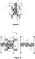
- FIG. 5 shows an example of non-correctable non-conformity where the profiles and alignments of the elements to be fitted, namely the jaws 11 and the notches 7, do not correspond.
- the driving system of the towing vehicle detects this situation and prevents the support 2 from being towed until the jaws 11 can be securely put in place.
- FIG. 6 shows another example of non-correctable non-compliance where one or more dimensions in relation to the support 2, for example the width or the length between the feet 4, makes it possible to detect that the support 2 is not compliant or compatible with the system 1 of towable supports.
- FIG. 7 illustrates an example of a correctable non-compliance.
- the towing vehicle is not well positioned. If the jaws 11 are retracted, detection of non-insertion of one of the jaws and partial insertion of other jaws makes it possible to see that the docking position has not been reached. The vehicle is then moved until securing can be carried out properly.
- the use of a tightening level detection sensor makes it possible to detect the following situation: the jaws tighten on a drawbar but not at the level of the notches with it being impossible to tighten fully, and unsecured detection.
Landscapes
- Engineering & Computer Science (AREA)
- Transportation (AREA)
- Mechanical Engineering (AREA)
- Health & Medical Sciences (AREA)
- Public Health (AREA)
- Handcart (AREA)
- Automatic Assembly (AREA)
- Fertilizing (AREA)
- Harvesting Machines For Root Crops (AREA)
Claims (8)
- System (1) aus schleppbaren Trägern, umfassend:i) eine erste Vielzahl beweglicher Träger (2), wobei jeder der Träger (2) ein Element zum Koppeln mit einem Schleppfahrzeug (10) umfasst, um es diesem Letzteren zu erlauben, den Träger (2) zu verlagern;ii) mindestens ein motorisiertes Schleppfahrzeug (10) mit Spannachse L-L, das eine Spannbaugruppe des Kopplungselements umfasst;dadurch gekennzeichnet, dass:a) das Kopplungselement eine längliche Zugstange (6) umfasst, deren Seitenflächen mit mindestens zwei entgegengesetzten Kerben (7) versehen sind;b) die Spannbaugruppe des Schleppfahrzeugs (10) mindestens zwei entgegengesetzte Backen (11) umfasst, die in Schienen (12) gleitend montiert sind, die in Bezug auf die Spannachse (L-L) des Schleppfahrzeugs (10) quer sind, wobei die Formen und Maße der Backen (11) und der Kerben eine Führung und eine Einfügung der Backen in die Kerben (7) des zu verlagernden Trägers (2) erlauben;c) und dass der Hub der Backen (11) entlang der Schienen (12) ausreicht, um ein Spannen der Zugstange (6) zu erlauben, wenn die Backen (11) in die Kerben (7) eingefügt sind.
- System (1) aus schleppbaren Trägern nach Anspruch 1, wobei mindestens eine Backe und bevorzugt mindestens eine Backe auf jeder Seite der Spannachse (L-L) einen vertikalen Riegel umfasst.
- System (1) aus schleppbaren Trägern nach Anspruch 1, wobei ein Beabstandungssensor mit den Backen (11) gekoppelt und dazu konzipiert ist, ein angemessenes Befestigungssignal zu liefern, wenn sich die Backen einander über einen gegebenen Schwellenwert, der einem angemessenen Befestigen entspricht, nähern.
- System (1) aus schleppbaren Trägern nach Anspruch 3, wobei ein Kraftsensor mit den Backen (11) gekoppelt und dazu eingerichtet ist, ein angemessenes Befestigungssignal zu liefern, wenn die Backen eine Auflagekraft größer als ein gegebener Schwellenwert, der einem angemessenen Befestigen entspricht, ausüben.
- System (1) aus schleppbaren Trägern nach Anspruch 1, wobei mindestens einer der Träger auf Füßen (4) montiert ist, die auf dem Boden rollen oder gleiten.
- System (1) aus schleppbaren Trägern nach einem der Ansprüche 3 bis 5, wobei die Verlagerung des Schleppfahrzeugs verriegelt wird, wenn eine nicht konforme Situation erfasst wird.
- System (1) aus schleppbaren Trägern nach einem der Ansprüche 1 bis 6, wobei mindestens eine der Backen (11) sowie die entsprechende Kerbe (7) ein von den anderen unterschiedliches Profil aufweist.
- System (1) aus schleppbaren Trägern nach einem der Ansprüche 1 bis 7, wobei die Backen (11) und die entsprechenden Kerben (7) konvergierende oder divergierende Profile in Richtung der Spannachse (L'-L') aufweisen.
Applications Claiming Priority (2)
| Application Number | Priority Date | Filing Date | Title |
|---|---|---|---|
| FR2006414A FR3111596B1 (fr) | 2020-06-19 | 2020-06-19 | Système de supports tractables |
| PCT/IB2021/055088 WO2021255586A1 (fr) | 2020-06-19 | 2021-06-10 | Systeme de supports tractables |
Publications (3)
| Publication Number | Publication Date |
|---|---|
| EP4132817A1 EP4132817A1 (de) | 2023-02-15 |
| EP4132817B1 true EP4132817B1 (de) | 2024-04-10 |
| EP4132817C0 EP4132817C0 (de) | 2024-04-10 |
Family
ID=72470543
Family Applications (1)
| Application Number | Title | Priority Date | Filing Date |
|---|---|---|---|
| EP21730679.4A Active EP4132817B1 (de) | 2020-06-19 | 2021-06-10 | System aus schleppbaren trägern |
Country Status (3)
| Country | Link |
|---|---|
| EP (1) | EP4132817B1 (de) |
| FR (1) | FR3111596B1 (de) |
| WO (1) | WO2021255586A1 (de) |
Family Cites Families (5)
| Publication number | Priority date | Publication date | Assignee | Title |
|---|---|---|---|---|
| US7402018B2 (en) | 2004-10-14 | 2008-07-22 | Kiva Systems, Inc. | Inventory system with mobile drive unit and inventory holder |
| US7850413B2 (en) * | 2007-01-05 | 2010-12-14 | Kiva Systems, Inc. | System and method for transporting inventory items |
| NL2019350B1 (nl) | 2017-07-07 | 2019-01-16 | Eurotec B V | Robotisch voertuig, systeem ermee en gebruik ervan. |
| WO2019009729A2 (en) * | 2017-07-07 | 2019-01-10 | Eurotec B.V. | ROBOTIC VEHICLE, SYSTEM AND USE THEREOF |
| EP3700838A1 (de) * | 2017-10-27 | 2020-09-02 | Berkshire Grey, Inc. | Systeme und verfahren zur verarbeitung von objekten mit mobilen matrixträgersystemen |
-
2020
- 2020-06-19 FR FR2006414A patent/FR3111596B1/fr active Active
-
2021
- 2021-06-10 EP EP21730679.4A patent/EP4132817B1/de active Active
- 2021-06-10 WO PCT/IB2021/055088 patent/WO2021255586A1/fr not_active Ceased
Also Published As
| Publication number | Publication date |
|---|---|
| EP4132817A1 (de) | 2023-02-15 |
| FR3111596B1 (fr) | 2022-07-22 |
| FR3111596A1 (fr) | 2021-12-24 |
| WO2021255586A1 (fr) | 2021-12-23 |
| EP4132817C0 (de) | 2024-04-10 |
Similar Documents
| Publication | Publication Date | Title |
|---|---|---|
| EP1743828B1 (de) | Anhänger für einen Lastzug und einen daraus hergestellten Lastzug | |
| FR3036349A1 (fr) | Convoyeurs mobiles destines au deplacement d'un vehicule a 4 roues. | |
| EP0233098B1 (de) | Verladevorrichtung zum Laden, insbesondere zum schnellen Transferieren von palettierten Lasten | |
| EP1742858B1 (de) | Anlage und verfahren zur übertragung einer last zwischen einer transferplattform und einem transportfahrzeug | |
| EP2847112B1 (de) | Gestell zum lagern und/oder transportieren von grossen glasscheiben | |
| EP3401251A1 (de) | Führungsträger oder -schiene, überladeanlage und verfahren zu dessen umsetzung | |
| EP2236445A1 (de) | Vorrichtung zum Halten eines LKW, Verfahren und Verwendung derselben | |
| EP2540530B1 (de) | Lastzug | |
| EP3191342B1 (de) | Transportfahrzeug mit erweiterter längsstruktur für eine motorbetriebene handhabungsvorrichtung | |
| EP4132817B1 (de) | System aus schleppbaren trägern | |
| FR3116779A1 (fr) | Procédé de chargement d’un véhicule à quatre roues et convoyeur de transport associé | |
| EP3377397B1 (de) | Fahrzeug zum transportieren einer last | |
| EP3585631B1 (de) | Berädertes logistikmodul mit einer abschleppvorrichtung | |
| FR2979609A1 (fr) | Remorque destinee au transport d'une pluralite de chariots equipes de roulettes, et dispositif de transport comprenant cette remorque | |
| EP3645446B1 (de) | Hubwagen mit ladestopp | |
| FR3071476B1 (fr) | Systeme de recuperation et de deploiement de sources sismiques et navire comportant un tel systeme et procedes associes | |
| FR3109756A1 (fr) | Système porteur de chariot | |
| FR2993824A1 (fr) | Dispositif pour atteler une remorque a un vehicule tracteur | |
| EP4543798A1 (de) | Autonomer gabelstapler zum transport von lasten und zugehöriges verfahren | |
| FR2749552A1 (fr) | Plateau intermediaire amovible d'arrimage et de manutention de boites par rapport a un vehicule, vehicule adapte, systeme de manutention de boites et procede correspondant | |
| EP4724286A1 (de) | Kupplungsvorrichtung zur kopplung an ein mobiles nutzfahrzeug und robotisches antriebssystem für mindestens ein mobiles nutzfahrzeug mit solch einer kupplungsvorrichtung | |
| FR3160913A1 (fr) | Systeme d’entrainement robotise d’au moins un chariot mobile | |
| WO2001098106A1 (fr) | Procede de chargement et de dechargement d'au moins une moto-marine pour son transport routier et remorque le mettant en oeuvre | |
| FR2484340A1 (fr) | Dispositif de transport et de stockage de vehicules automobiles | |
| WO2025133498A1 (fr) | Véhicule pour système automatisé de stockage et de récupération d'articles |
Legal Events
| Date | Code | Title | Description |
|---|---|---|---|
| STAA | Information on the status of an ep patent application or granted ep patent |
Free format text: STATUS: UNKNOWN |
|
| STAA | Information on the status of an ep patent application or granted ep patent |
Free format text: STATUS: THE INTERNATIONAL PUBLICATION HAS BEEN MADE |
|
| PUAI | Public reference made under article 153(3) epc to a published international application that has entered the european phase |
Free format text: ORIGINAL CODE: 0009012 |
|
| STAA | Information on the status of an ep patent application or granted ep patent |
Free format text: STATUS: REQUEST FOR EXAMINATION WAS MADE |
|
| 17P | Request for examination filed |
Effective date: 20221106 |
|
| AK | Designated contracting states |
Kind code of ref document: A1 Designated state(s): AL AT BE BG CH CY CZ DE DK EE ES FI FR GB GR HR HU IE IS IT LI LT LU LV MC MK MT NL NO PL PT RO RS SE SI SK SM TR |
|
| DAV | Request for validation of the european patent (deleted) | ||
| DAX | Request for extension of the european patent (deleted) | ||
| GRAP | Despatch of communication of intention to grant a patent |
Free format text: ORIGINAL CODE: EPIDOSNIGR1 |
|
| STAA | Information on the status of an ep patent application or granted ep patent |
Free format text: STATUS: GRANT OF PATENT IS INTENDED |
|
| INTG | Intention to grant announced |
Effective date: 20231205 |
|
| GRAS | Grant fee paid |
Free format text: ORIGINAL CODE: EPIDOSNIGR3 |
|
| GRAA | (expected) grant |
Free format text: ORIGINAL CODE: 0009210 |
|
| STAA | Information on the status of an ep patent application or granted ep patent |
Free format text: STATUS: THE PATENT HAS BEEN GRANTED |
|
| AK | Designated contracting states |
Kind code of ref document: B1 Designated state(s): AL AT BE BG CH CY CZ DE DK EE ES FI FR GB GR HR HU IE IS IT LI LT LU LV MC MK MT NL NO PL PT RO RS SE SI SK SM TR |
|
| REG | Reference to a national code |
Ref country code: GB Ref legal event code: FG4D Free format text: NOT ENGLISH |
|
| REG | Reference to a national code |
Ref country code: CH Ref legal event code: EP |
|
| REG | Reference to a national code |
Ref country code: DE Ref legal event code: R096 Ref document number: 602021011685 Country of ref document: DE |
|
| REG | Reference to a national code |
Ref country code: IE Ref legal event code: FG4D Free format text: LANGUAGE OF EP DOCUMENT: FRENCH |
|
| U01 | Request for unitary effect filed |
Effective date: 20240411 |
|
| U07 | Unitary effect registered |
Designated state(s): AT BE BG DE DK EE FI FR IT LT LU LV MT NL PT SE SI Effective date: 20240426 |
|
| U20 | Renewal fee for the european patent with unitary effect paid |
Year of fee payment: 4 Effective date: 20240630 |
|
| PG25 | Lapsed in a contracting state [announced via postgrant information from national office to epo] |
Ref country code: IS Free format text: LAPSE BECAUSE OF FAILURE TO SUBMIT A TRANSLATION OF THE DESCRIPTION OR TO PAY THE FEE WITHIN THE PRESCRIBED TIME-LIMIT Effective date: 20240810 |
|
| PG25 | Lapsed in a contracting state [announced via postgrant information from national office to epo] |
Ref country code: HR Free format text: LAPSE BECAUSE OF FAILURE TO SUBMIT A TRANSLATION OF THE DESCRIPTION OR TO PAY THE FEE WITHIN THE PRESCRIBED TIME-LIMIT Effective date: 20240410 |
|
| PG25 | Lapsed in a contracting state [announced via postgrant information from national office to epo] |
Ref country code: GR Free format text: LAPSE BECAUSE OF FAILURE TO SUBMIT A TRANSLATION OF THE DESCRIPTION OR TO PAY THE FEE WITHIN THE PRESCRIBED TIME-LIMIT Effective date: 20240711 |
|
| PG25 | Lapsed in a contracting state [announced via postgrant information from national office to epo] |
Ref country code: ES Free format text: LAPSE BECAUSE OF FAILURE TO SUBMIT A TRANSLATION OF THE DESCRIPTION OR TO PAY THE FEE WITHIN THE PRESCRIBED TIME-LIMIT Effective date: 20240410 |
|
| PG25 | Lapsed in a contracting state [announced via postgrant information from national office to epo] |
Ref country code: PL Free format text: LAPSE BECAUSE OF FAILURE TO SUBMIT A TRANSLATION OF THE DESCRIPTION OR TO PAY THE FEE WITHIN THE PRESCRIBED TIME-LIMIT Effective date: 20240410 |
|
| PG25 | Lapsed in a contracting state [announced via postgrant information from national office to epo] |
Ref country code: NO Free format text: LAPSE BECAUSE OF FAILURE TO SUBMIT A TRANSLATION OF THE DESCRIPTION OR TO PAY THE FEE WITHIN THE PRESCRIBED TIME-LIMIT Effective date: 20240710 Ref country code: IS Free format text: LAPSE BECAUSE OF FAILURE TO SUBMIT A TRANSLATION OF THE DESCRIPTION OR TO PAY THE FEE WITHIN THE PRESCRIBED TIME-LIMIT Effective date: 20240810 Ref country code: HR Free format text: LAPSE BECAUSE OF FAILURE TO SUBMIT A TRANSLATION OF THE DESCRIPTION OR TO PAY THE FEE WITHIN THE PRESCRIBED TIME-LIMIT Effective date: 20240410 Ref country code: GR Free format text: LAPSE BECAUSE OF FAILURE TO SUBMIT A TRANSLATION OF THE DESCRIPTION OR TO PAY THE FEE WITHIN THE PRESCRIBED TIME-LIMIT Effective date: 20240711 Ref country code: ES Free format text: LAPSE BECAUSE OF FAILURE TO SUBMIT A TRANSLATION OF THE DESCRIPTION OR TO PAY THE FEE WITHIN THE PRESCRIBED TIME-LIMIT Effective date: 20240410 Ref country code: PL Free format text: LAPSE BECAUSE OF FAILURE TO SUBMIT A TRANSLATION OF THE DESCRIPTION OR TO PAY THE FEE WITHIN THE PRESCRIBED TIME-LIMIT Effective date: 20240410 Ref country code: RS Free format text: LAPSE BECAUSE OF FAILURE TO SUBMIT A TRANSLATION OF THE DESCRIPTION OR TO PAY THE FEE WITHIN THE PRESCRIBED TIME-LIMIT Effective date: 20240710 |
|
| REG | Reference to a national code |
Ref country code: DE Ref legal event code: R097 Ref document number: 602021011685 Country of ref document: DE |
|
| PG25 | Lapsed in a contracting state [announced via postgrant information from national office to epo] |
Ref country code: CZ Free format text: LAPSE BECAUSE OF FAILURE TO SUBMIT A TRANSLATION OF THE DESCRIPTION OR TO PAY THE FEE WITHIN THE PRESCRIBED TIME-LIMIT Effective date: 20240410 |
|
| PG25 | Lapsed in a contracting state [announced via postgrant information from national office to epo] |
Ref country code: SK Free format text: LAPSE BECAUSE OF FAILURE TO SUBMIT A TRANSLATION OF THE DESCRIPTION OR TO PAY THE FEE WITHIN THE PRESCRIBED TIME-LIMIT Effective date: 20240410 Ref country code: RO Free format text: LAPSE BECAUSE OF FAILURE TO SUBMIT A TRANSLATION OF THE DESCRIPTION OR TO PAY THE FEE WITHIN THE PRESCRIBED TIME-LIMIT Effective date: 20240410 |
|
| PG25 | Lapsed in a contracting state [announced via postgrant information from national office to epo] |
Ref country code: SM Free format text: LAPSE BECAUSE OF FAILURE TO SUBMIT A TRANSLATION OF THE DESCRIPTION OR TO PAY THE FEE WITHIN THE PRESCRIBED TIME-LIMIT Effective date: 20240410 |
|
| PG25 | Lapsed in a contracting state [announced via postgrant information from national office to epo] |
Ref country code: SM Free format text: LAPSE BECAUSE OF FAILURE TO SUBMIT A TRANSLATION OF THE DESCRIPTION OR TO PAY THE FEE WITHIN THE PRESCRIBED TIME-LIMIT Effective date: 20240410 Ref country code: SK Free format text: LAPSE BECAUSE OF FAILURE TO SUBMIT A TRANSLATION OF THE DESCRIPTION OR TO PAY THE FEE WITHIN THE PRESCRIBED TIME-LIMIT Effective date: 20240410 Ref country code: RO Free format text: LAPSE BECAUSE OF FAILURE TO SUBMIT A TRANSLATION OF THE DESCRIPTION OR TO PAY THE FEE WITHIN THE PRESCRIBED TIME-LIMIT Effective date: 20240410 Ref country code: CZ Free format text: LAPSE BECAUSE OF FAILURE TO SUBMIT A TRANSLATION OF THE DESCRIPTION OR TO PAY THE FEE WITHIN THE PRESCRIBED TIME-LIMIT Effective date: 20240410 Ref country code: MC Free format text: LAPSE BECAUSE OF FAILURE TO SUBMIT A TRANSLATION OF THE DESCRIPTION OR TO PAY THE FEE WITHIN THE PRESCRIBED TIME-LIMIT Effective date: 20240410 |
|
| REG | Reference to a national code |
Ref country code: CH Ref legal event code: PL |
|
| PLBE | No opposition filed within time limit |
Free format text: ORIGINAL CODE: 0009261 |
|
| STAA | Information on the status of an ep patent application or granted ep patent |
Free format text: STATUS: NO OPPOSITION FILED WITHIN TIME LIMIT |
|
| 26N | No opposition filed |
Effective date: 20250113 |
|
| PG25 | Lapsed in a contracting state [announced via postgrant information from national office to epo] |
Ref country code: IE Free format text: LAPSE BECAUSE OF NON-PAYMENT OF DUE FEES Effective date: 20240610 |
|
| PG25 | Lapsed in a contracting state [announced via postgrant information from national office to epo] |
Ref country code: CH Free format text: LAPSE BECAUSE OF NON-PAYMENT OF DUE FEES Effective date: 20240630 |
|
| U20 | Renewal fee for the european patent with unitary effect paid |
Year of fee payment: 5 Effective date: 20250403 |
|
| PGFP | Annual fee paid to national office [announced via postgrant information from national office to epo] |
Ref country code: GB Payment date: 20250403 Year of fee payment: 5 |
|
| PG25 | Lapsed in a contracting state [announced via postgrant information from national office to epo] |
Ref country code: CY Free format text: LAPSE BECAUSE OF FAILURE TO SUBMIT A TRANSLATION OF THE DESCRIPTION OR TO PAY THE FEE WITHIN THE PRESCRIBED TIME-LIMIT; INVALID AB INITIO Effective date: 20210610 |
|
| PG25 | Lapsed in a contracting state [announced via postgrant information from national office to epo] |
Ref country code: HU Free format text: LAPSE BECAUSE OF FAILURE TO SUBMIT A TRANSLATION OF THE DESCRIPTION OR TO PAY THE FEE WITHIN THE PRESCRIBED TIME-LIMIT; INVALID AB INITIO Effective date: 20210610 |