EP4132843B1 - Tragstruktur zur montage von windenergiegewinnungsmodulen - Google Patents
Tragstruktur zur montage von windenergiegewinnungsmodulen Download PDFInfo
- Publication number
- EP4132843B1 EP4132843B1 EP21720567.3A EP21720567A EP4132843B1 EP 4132843 B1 EP4132843 B1 EP 4132843B1 EP 21720567 A EP21720567 A EP 21720567A EP 4132843 B1 EP4132843 B1 EP 4132843B1
- Authority
- EP
- European Patent Office
- Prior art keywords
- modules
- wind energy
- energy collection
- floating
- supporting
- Prior art date
- Legal status (The legal status is an assumption and is not a legal conclusion. Google has not performed a legal analysis and makes no representation as to the accuracy of the status listed.)
- Active
Links
Images




Classifications
-
- B—PERFORMING OPERATIONS; TRANSPORTING
- B63—SHIPS OR OTHER WATERBORNE VESSELS; RELATED EQUIPMENT
- B63B—SHIPS OR OTHER WATERBORNE VESSELS; EQUIPMENT FOR SHIPPING
- B63B1/00—Hydrodynamic or hydrostatic features of hulls or of hydrofoils
- B63B1/02—Hydrodynamic or hydrostatic features of hulls or of hydrofoils deriving lift mainly from water displacement
- B63B1/10—Hydrodynamic or hydrostatic features of hulls or of hydrofoils deriving lift mainly from water displacement with multiple hulls
- B63B1/14—Hydrodynamic or hydrostatic features of hulls or of hydrofoils deriving lift mainly from water displacement with multiple hulls the hulls being interconnected resiliently or having means for actively varying hull shape or configuration
-
- B—PERFORMING OPERATIONS; TRANSPORTING
- B63—SHIPS OR OTHER WATERBORNE VESSELS; RELATED EQUIPMENT
- B63B—SHIPS OR OTHER WATERBORNE VESSELS; EQUIPMENT FOR SHIPPING
- B63B21/00—Tying-up; Shifting, towing, or pushing equipment; Anchoring
- B63B21/50—Anchoring arrangements or methods for special vessels, e.g. for floating drilling platforms or dredgers
-
- B—PERFORMING OPERATIONS; TRANSPORTING
- B63—SHIPS OR OTHER WATERBORNE VESSELS; RELATED EQUIPMENT
- B63B—SHIPS OR OTHER WATERBORNE VESSELS; EQUIPMENT FOR SHIPPING
- B63B75/00—Building or assembling floating offshore structures, e.g. semi-submersible platforms, SPAR platforms or wind turbine platforms
-
- F—MECHANICAL ENGINEERING; LIGHTING; HEATING; WEAPONS; BLASTING
- F03—MACHINES OR ENGINES FOR LIQUIDS; WIND, SPRING, OR WEIGHT MOTORS; PRODUCING MECHANICAL POWER OR A REACTIVE PROPULSIVE THRUST, NOT OTHERWISE PROVIDED FOR
- F03D—WIND MOTORS
- F03D13/00—Assembly, mounting or commissioning of wind motors; Arrangements specially adapted for transporting wind motor components
- F03D13/20—Arrangements for mounting or supporting wind motors; Masts or towers for wind motors
- F03D13/25—Arrangements for mounting or supporting wind motors; Masts or towers for wind motors specially adapted for offshore installation
-
- B—PERFORMING OPERATIONS; TRANSPORTING
- B63—SHIPS OR OTHER WATERBORNE VESSELS; RELATED EQUIPMENT
- B63B—SHIPS OR OTHER WATERBORNE VESSELS; EQUIPMENT FOR SHIPPING
- B63B35/00—Vessels or similar floating structures specially adapted for specific purposes and not otherwise provided for
- B63B35/44—Floating buildings, stores, drilling platforms, or workshops, e.g. carrying water-oil separating devices
- B63B2035/4433—Floating structures carrying electric power plants
- B63B2035/446—Floating structures carrying electric power plants for converting wind energy into electric energy
-
- F—MECHANICAL ENGINEERING; LIGHTING; HEATING; WEAPONS; BLASTING
- F03—MACHINES OR ENGINES FOR LIQUIDS; WIND, SPRING, OR WEIGHT MOTORS; PRODUCING MECHANICAL POWER OR A REACTIVE PROPULSIVE THRUST, NOT OTHERWISE PROVIDED FOR
- F03B—MACHINES OR ENGINES FOR LIQUIDS
- F03B13/00—Adaptations of machines or engines for special use; Combinations of machines or engines with driving or driven apparatus; Power stations or aggregates
- F03B13/12—Adaptations of machines or engines for special use; Combinations of machines or engines with driving or driven apparatus; Power stations or aggregates characterised by using wave or tide energy
- F03B13/14—Adaptations of machines or engines for special use; Combinations of machines or engines with driving or driven apparatus; Power stations or aggregates characterised by using wave or tide energy using wave energy
- F03B13/16—Adaptations of machines or engines for special use; Combinations of machines or engines with driving or driven apparatus; Power stations or aggregates characterised by using wave or tide energy using wave energy using the relative movement between a wave-operated member, i.e. a "wom" and another member, i.e. a reaction member or "rem"
- F03B13/20—Adaptations of machines or engines for special use; Combinations of machines or engines with driving or driven apparatus; Power stations or aggregates characterised by using wave or tide energy using wave energy using the relative movement between a wave-operated member, i.e. a "wom" and another member, i.e. a reaction member or "rem" wherein both members, i.e. wom and rem are movable relative to the sea bed or shore
-
- F—MECHANICAL ENGINEERING; LIGHTING; HEATING; WEAPONS; BLASTING
- F03—MACHINES OR ENGINES FOR LIQUIDS; WIND, SPRING, OR WEIGHT MOTORS; PRODUCING MECHANICAL POWER OR A REACTIVE PROPULSIVE THRUST, NOT OTHERWISE PROVIDED FOR
- F03D—WIND MOTORS
- F03D9/00—Adaptations of wind motors for special use; Combinations of wind motors with apparatus driven thereby; Wind motors specially adapted for installation in particular locations
- F03D9/008—Adaptations of wind motors for special use; Combinations of wind motors with apparatus driven thereby; Wind motors specially adapted for installation in particular locations the wind motor being combined with water energy converters, e.g. a water turbine
-
- F—MECHANICAL ENGINEERING; LIGHTING; HEATING; WEAPONS; BLASTING
- F05—INDEXING SCHEMES RELATING TO ENGINES OR PUMPS IN VARIOUS SUBCLASSES OF CLASSES F01-F04
- F05B—INDEXING SCHEME RELATING TO WIND, SPRING, WEIGHT, INERTIA OR LIKE MOTORS, TO MACHINES OR ENGINES FOR LIQUIDS COVERED BY SUBCLASSES F03B, F03D AND F03G
- F05B2240/00—Components
- F05B2240/90—Mounting on supporting structures or systems
- F05B2240/93—Mounting on supporting structures or systems on a structure floating on a liquid surface
-
- F—MECHANICAL ENGINEERING; LIGHTING; HEATING; WEAPONS; BLASTING
- F05—INDEXING SCHEMES RELATING TO ENGINES OR PUMPS IN VARIOUS SUBCLASSES OF CLASSES F01-F04
- F05B—INDEXING SCHEME RELATING TO WIND, SPRING, WEIGHT, INERTIA OR LIKE MOTORS, TO MACHINES OR ENGINES FOR LIQUIDS COVERED BY SUBCLASSES F03B, F03D AND F03G
- F05B2240/00—Components
- F05B2240/90—Mounting on supporting structures or systems
- F05B2240/96—Mounting on supporting structures or systems as part of a wind turbine farm
-
- F—MECHANICAL ENGINEERING; LIGHTING; HEATING; WEAPONS; BLASTING
- F05—INDEXING SCHEMES RELATING TO ENGINES OR PUMPS IN VARIOUS SUBCLASSES OF CLASSES F01-F04
- F05B—INDEXING SCHEME RELATING TO WIND, SPRING, WEIGHT, INERTIA OR LIKE MOTORS, TO MACHINES OR ENGINES FOR LIQUIDS COVERED BY SUBCLASSES F03B, F03D AND F03G
- F05B2240/00—Components
- F05B2240/90—Mounting on supporting structures or systems
- F05B2240/97—Mounting on supporting structures or systems on a submerged structure
-
- F—MECHANICAL ENGINEERING; LIGHTING; HEATING; WEAPONS; BLASTING
- F05—INDEXING SCHEMES RELATING TO ENGINES OR PUMPS IN VARIOUS SUBCLASSES OF CLASSES F01-F04
- F05B—INDEXING SCHEME RELATING TO WIND, SPRING, WEIGHT, INERTIA OR LIKE MOTORS, TO MACHINES OR ENGINES FOR LIQUIDS COVERED BY SUBCLASSES F03B, F03D AND F03G
- F05B2250/00—Geometry
- F05B2250/10—Geometry two-dimensional
- F05B2250/13—Geometry two-dimensional trapezial
-
- F—MECHANICAL ENGINEERING; LIGHTING; HEATING; WEAPONS; BLASTING
- F05—INDEXING SCHEMES RELATING TO ENGINES OR PUMPS IN VARIOUS SUBCLASSES OF CLASSES F01-F04
- F05B—INDEXING SCHEME RELATING TO WIND, SPRING, WEIGHT, INERTIA OR LIKE MOTORS, TO MACHINES OR ENGINES FOR LIQUIDS COVERED BY SUBCLASSES F03B, F03D AND F03G
- F05B2260/00—Function
- F05B2260/30—Retaining components in desired mutual position
-
- Y—GENERAL TAGGING OF NEW TECHNOLOGICAL DEVELOPMENTS; GENERAL TAGGING OF CROSS-SECTIONAL TECHNOLOGIES SPANNING OVER SEVERAL SECTIONS OF THE IPC; TECHNICAL SUBJECTS COVERED BY FORMER USPC CROSS-REFERENCE ART COLLECTIONS [XRACs] AND DIGESTS
- Y02—TECHNOLOGIES OR APPLICATIONS FOR MITIGATION OR ADAPTATION AGAINST CLIMATE CHANGE
- Y02E—REDUCTION OF GREENHOUSE GAS [GHG] EMISSIONS, RELATED TO ENERGY GENERATION, TRANSMISSION OR DISTRIBUTION
- Y02E10/00—Energy generation through renewable energy sources
- Y02E10/70—Wind energy
- Y02E10/72—Wind turbines with rotation axis in wind direction
-
- Y—GENERAL TAGGING OF NEW TECHNOLOGICAL DEVELOPMENTS; GENERAL TAGGING OF CROSS-SECTIONAL TECHNOLOGIES SPANNING OVER SEVERAL SECTIONS OF THE IPC; TECHNICAL SUBJECTS COVERED BY FORMER USPC CROSS-REFERENCE ART COLLECTIONS [XRACs] AND DIGESTS
- Y02—TECHNOLOGIES OR APPLICATIONS FOR MITIGATION OR ADAPTATION AGAINST CLIMATE CHANGE
- Y02E—REDUCTION OF GREENHOUSE GAS [GHG] EMISSIONS, RELATED TO ENERGY GENERATION, TRANSMISSION OR DISTRIBUTION
- Y02E10/00—Energy generation through renewable energy sources
- Y02E10/70—Wind energy
- Y02E10/727—Offshore wind turbines
-
- Y—GENERAL TAGGING OF NEW TECHNOLOGICAL DEVELOPMENTS; GENERAL TAGGING OF CROSS-SECTIONAL TECHNOLOGIES SPANNING OVER SEVERAL SECTIONS OF THE IPC; TECHNICAL SUBJECTS COVERED BY FORMER USPC CROSS-REFERENCE ART COLLECTIONS [XRACs] AND DIGESTS
- Y02—TECHNOLOGIES OR APPLICATIONS FOR MITIGATION OR ADAPTATION AGAINST CLIMATE CHANGE
- Y02E—REDUCTION OF GREENHOUSE GAS [GHG] EMISSIONS, RELATED TO ENERGY GENERATION, TRANSMISSION OR DISTRIBUTION
- Y02E70/00—Other energy conversion or management systems reducing GHG emissions
- Y02E70/30—Systems combining energy storage with energy generation of non-fossil origin
Definitions
- the present invention relates to a supporting structure for installing wind energy capture modules.
- This process applies in particular, but not exclusively, to the installation of wind energy capture modules placed on onshore or offshore ground as well as to the installation of floating wind energy capture modules.
- the installed offshore wind turbines are installed individually using either a gravity base of several thousand tonnes (bucket, gravity) requiring significant maritime engineering work on the ground, or deep drilling for so-called “monopile” installations. or a “jacket” type base itself fixed by means of a drilling at each foot.
- a gravity base of several thousand tonnes (bucket, gravity) requiring significant maritime engineering work on the ground, or deep drilling for so-called “monopile” installations.
- a “jacket” type base itself fixed by means of a drilling at each foot.
- drilling is known for its high cost and disastrous impact on the environment.
- Floating offshore wind turbines are installed individually using very large floats and ballast to ensure their verticality and are held in position by complex anchors, which are therefore also expensive.
- the present invention reduces these drawbacks by proposing the use of a supporting support structure common to a set of wind energy capture modules.
- Each module contributing to the balance of adjacent modules either by its weight or by its buoyancy, the principle is to maintain the positioning of these said modules and guarantee, when desired, their verticality by a common supporting structure, generally horizontal , articulated or not.
- the wind energy collection modules are secured to the rest of the supporting structure in a fixed manner or via systems forming slides, for example with skates or rollers.
- Stringers, spars or, where applicable, cables connect the modules to each other, either to intermediate or peripheral masses in the case of installed modules, or to floating boxes in the case of floating offshore modules.
- the patent WO 2015063215 is the closest to the proposed concept, knowing that it presents means of navigation and installation on site thanks to a supporting structure consisting in particular of buoyancy bodies arranged at the vertices of a parallelogram; nevertheless, there is no reference to a possibility of association of several structures of this type.
- WO 2013/040871 A1 describes a floating platform supporting a wind turbine whose barrel is connected to floats by beams constituting a one-piece assembly.
- FR 2 990 477 A1 describes a set of offshore wind turbines each comprising flotation means anchored to the seabed, at least two wind turbines being connected by connecting means consisting of crossed cables.
- the vertical maintenance of wind turbine masts is not guaranteed; in fact, it is only ensured if the cables are always in tension, which cannot be the case for an offshore assembly. This process does not seem compatible with operation in a marine environment subject to swell, as well as strong variations in level and current due to tides. Such cables subjected to intermittent tensions can therefore transmit very strong stresses to the different elements and break at any time.
- FR 2 990 476 A1 describes a wind turbine on a floating support comprising a system for maintaining the wind turbine in a privileged position.
- Such a system is referred to by the Examiner as “gimbal means”.
- Such means do not form part of the means authorizing a variation or adjustment of the distance and/or height between the different modules.
- CN 110 296 049 A shows a one-piece assembly comprising a wind turbine whose shaft is connected to floating boxes by beams without any articulation to the shaft.
- each wind turbine which uses in particular a connection by slide and/or articulated parallelogram(s)
- the balance and verticality of each wind turbine module are ensured by the adjacent modules or by the adjacent modules and by the ballast, in the case where ballast is present.
- each wind turbine can, for its vertical support, rely on the flotation of the adjacent wind turbine(s).
- the vertical play makes it possible to follow the swell movements.
- a sill designates here any assembly of beams, stringers or any elongated structure, oriented horizontally, capable of supporting significant loads and able to be articulated at its vertices.
- the essentially vertical short side(s) connect the modules, directly or by means of intermediate devices, to the boxes, masses, or pylons.
- Certain specific stringers or sills contributing only to the positioning of the modules and floating boxes within the structure may only have one fixing point per end.
- elements such as piles on boreholes, suction box type foundations, gravity masses, support points, foundations, anchors, intermediate floating boxes and additional floats will be integrated so as to ensure the balance and maintenance of the entire supporting structure.
- Their number per collection module will, however, be greatly reduced compared to an installation per independent module.
- the vertical stability of the floating wind energy capture modules can partly be ensured intrinsically and individually by means of the righting torque generated by their ballast and their reserve of own buoyancy.
- wind energy conversion devices such as electric generators, pumps or compressors, usually located at the top of the mast can be installed in the lower part, that is to say in the barrel or at the base of the mast.
- dynamic stabilization means such as gyroscopic or by load transfer not shown can reinforce said rectifying torque of the modules; the horizontality of the entire structure can be improved by controlling floats with variable buoyancy (ballasts).
- said means for damping deformation of the supporting structure and/or vertical oscillation of the floating wind energy capture modules may be subject to so-called wave energy recovery thanks to the operation of jacks. , hydrodynamic brakes or mass transfer devices not shown.
- the module in the case where a strictly vertical maintenance of the floating wind energy capture modules is not required, for example to allow a certain erasure during oversales and thus limit the forces on the supporting structure , the module can be connected to said supporting structure by cardan means or equivalent not shown, or by flexible means such as cables.
- different supporting structures can be assembled together, for example so as to constitute a semi-rigid peripheral frame supporting subassemblies or single modules held by cables arranged radially and/or orthogonally; the forces inside the surface delimited by the frame being essentially traction forces.
- the electrical energy evacuation lines, not shown, coming from the different modules can be shared into a single one, the different connections being made in the aerial part of the modules and the electrical cables will thus be carried by the different elements of the supporting structure according to well-known and commonly used techniques.
- the supporting structure comprising the complete floating wind energy collection modules, that is to say the assembly constituted by the barrel, the mast and the wind generator, or comprising only the barrels, will authorize movement by towing towards the installation site, then secondly, mooring on the underwater floor.
- the supporting structure comprising the wind energy collection modules installed offshore will allow movement by towing to the installation site then its immersion in situ.
- the height of the barrels may be subject to prior adjustment by construction or by means of a telescopic foot not shown.
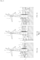
- the supporting structure combines in the upper part barrels (11) wind energy collection modules (1), arranged along a main axis XX' which is essentially vertical; they consist of a wind generator (13) secured to a mast (12) fixed by its base to a barrel (11).
- the supporting structure consists of at least two sills (2) arranged on the periphery of the barrel (11), in a plane containing the main axis XX' of the barrel (11), and of which a short side (28) is associated either to the barrel (11) or to the box (6).
- the assembly is shown installed inshore or offshore.
- the loose soil allows partial burial of the base of the barrel (11).
- It is connected on the one hand to an adjacent module (1) not shown by a rectangular sill (2) and on the other hand to a solid (4) by a triangular sill (2).
- the short side (28) of the sills is here assembled integrally (17) with the barrel (11). and the top of the triangular sill which is opposite it is fixed to the solid (4) by a joint (23).
- the articulated polygons (22), made up of parallelograms assembled two by two, are made up of arms associated by joints (23) with a common central arm (27) which is essentially vertical.
- These polygons are assembled in such a way that they impose a parallel maintenance of the short sides (28) of the sill (2) with the axis of the barrel (11) and the box (6) while allowing a slight between them. vertical and/or horizontal movement.
- a slide (26) secured to the barrel (11) or the box (6) makes it possible to increase the amplitude of the above vertical movement if necessary.
- Each barrel (11) or floating box (6) can be connected to a massive (4) or any other support placed on the underwater floor by means of a mooring device (18) and a cable (7 )
- the modules (1) for capturing wind energy are installed, onshore and/or offshore if necessary partially buried according to the figures 2a and 2b , .and placed, for example on rocky ground, as in the case of the figure 2c
- the installed wind energy capture module (1) can be associated with a massif (4) or a pylon (5) by means of a sill (2), the tops of which can be provided with joints ( 23).
- the wind energy capture module (1) is shown placed on soft ground, either inshore or offshore. Partial burial in the ground prevents the module (1) from shifting and thus contributes to maintaining the entire structure of which it is integral.
- two stringers (2) hold the module (1) along the axis XX' by their short side (28).
- a sill (2) of triangular shape connects the barrel (11) to a block (4) fixed to the opposite top of the short side (28), itself fixed to the barrel in an integral manner (17).
- a partially buried rectangular sill is assembled to the barrel (11) by means of a slide (26). The said slide allows a slight vertical movement of the module, particularly in the event of ground compaction.
- the wind energy capture module (1) is represented onshore according to the left part of the figure and offshore according to the right part.
- two parallelogram-shaped stringers (2) hold the module (1) for capturing wind energy along the vertical axis XX'.
- the connections between the sills (2) and the barrel (11) are either fixed or sliding by means of the slide (26).
- a brake or immobilizer system not shown can complete the assembly of the short side (28) to the slide (26).
- the module (1) is shown placed either onshore or offshore on firm ground.
- stringers (2) hold the module (1) for capturing wind energy along a vertical axis XX'
- the connections between the stringers (2) and the barrel (11) are either fixed , either sliding by means of the slide (26) associated with a single parallelogram (21) or a double parallelogram (22).
- supports (9) such as piles, pylons or masses support the stringers (2), which allows the horizontal maintenance of the base of the structure and subsequently maintaining the wind energy capture module (1) vertically.
- THE figures 3a, 3b, 3c represent the main solutions for assembling in floating mode the modules (1) and boxes (6) with the stringers (2).
- the module (1) for capturing wind energy consists of a barrel (11) supporting, near its upper part, a mast (12), which is integral with a wind generator (13).
- stringers (2) maintain the module (1) for capturing wind energy along the axis XX' essentially vertical.
- the barrel (11) and the sills (2) are associated by their short side (28) with a double parallelogram (22) by means of joints (23).
- the floating box (6) is connected to the barrel (11) by a triangular sill (2) and via a double parallelogram (22).
- the sill is rectangular in shape and provided with diagonal reinforcements (20).
- the barrel (11) includes a ballast (14)
- the double parallelograms (22) are associated with floats (61).
- the box (6) and the barrel (11) are connected to a massif (4) by moorings (7) by means of fixing devices (18).
- the module (1) for capturing wind energy consists of a barrel (11) supporting, near its upper part, a mast (12), which is integral with a wind generator (13).
- stringers (2) maintain the module (1) for capturing wind energy along the axis XX' essentially vertical.
- the barrel (11) and the sills (2) are associated by the short side (28) with a double parallelogram (22) by means of joints (23).
- the connections between the sills (2) and the double parallelograms (22) are sliding by means of the slides (26).
- the barrel (11) comprises a ballast (14) extended in its lower part by an axis (15) which makes it possible to associate the lower parts of the double parallelograms together thanks to the arms (29) and the lower part of the module (1) by means of a slider not shown
- a floating box (6) is associated, on the left of the figure, with a sill (2) in the shape of a parallelogram comprising cylinders (24) as well as springs (25); and on the right of the figure to a rectangular shaped sill.
- These said sills (2) are each associated by at least one of their short sides (28) with a double parallelogram (22) comprising jacks (24) and springs (25), On the left side this double articulated parallelogram (22) slides along the long box (6) by means of the slide (26).
- the box (6) comprises a ballast (14) extended in its lower part by an axis (15) which, thanks to the arms (29) and a slide not shown, makes it possible to associate the double parallelograms (22) with each other thus only at the lower part of the box (6)
- Floats (61) connected on the one hand to the upper part of the common central arm (27), and on the other hand to the upper part of the sills (2) participate in maintaining the entire structure horizontally.
- a mooring line (7) connects the box (6) to an anchoring block (4) by means of fixing devices (18)
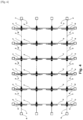
- modules (1) for capturing wind energy are installed onshore or offshore and associated in a network according to an orthogonal structure in accordance with the descriptions previously set out in the figures 2a, 2b and 2c . They are each connected by four branches made up of stringers (2). Support blocks (4) are arranged on the periphery of the network and connected to said network by stringers (2).
- modules (1) for capturing wind energy are floating offshore and associated in a network according to an orthogonal structure in accordance with the descriptions previously set out in the figures 3a, 3b and 3c . They are each connected by four branches mainly made up of stringers (2) as well as by retaining cables (3).
- the peripheral modules (1) are associated with floating boxes (6) which contribute to their balance.
- Peripheral sills (32) connect the boxes together.
- the entire network includes two holding cables (3) arranged diagonally.
- Anchoring blocks (4) are arranged at the periphery of the network and connected to said network by anchoring cables (7).
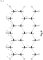
- modules (1) for capturing wind energy are installed onshore or offshore, associated in a network according to a honeycomb structure and in accordance with the descriptions previously set out in the figures 2a, 2b and 2c . They are each connected by three branches mainly made up of stringers (2). Support masses (4) connected to said network by stringers (2) are arranged on the periphery.
- modules (1) for capturing wind energy are floating offshore and associated with each of their three branches mainly made up of stringers (2) with a floating box (6), in accordance with the descriptions previously set out in the figures 3a, 3b and 3c .
- Spars (32) or peripheral sills connect the three boxes (6) arranged around each module (1).
- the network is made up of the assembly of sub-assemblies made up of the modules (1) connected to their three respective boxes. These said sub-assemblies are linked together at the level of the boxes (6) by holding cables (3).
- Anchoring blocks (4) are arranged at the periphery of the network and connected to floating boxes (6) by anchoring cables (7). This arrangement aims to space out the propellers of the modules (1) without requiring the use of spars (32) or sills of great length.
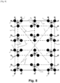
- modules (1) for capturing wind energy are floating offshore and associated with each of their three branches mainly made up of stringers (2) with a floating box (6), in accordance with the descriptions previously set out in the figures 3a, 3b and 3c .
- Peripheral longitudinal beams or sills (32) connect, while maintaining the positioning between them, the three boxes (6) arranged around each module (1).
- the main structure is made up of the assembly of sub-assemblies made up of the modules (1) connected to their three respective boxes.
- the floating boxes (6) located on the periphery of the network are connected by stringers (32) or sills (2).
- these said sub-assemblies are connected together at the level of the boxes (6) by retaining cables (3). Furthermore, the main structure includes two cables (3) of maintained arranged in its diagonals. Anchoring blocks (4) are arranged at the periphery of the network and connected to floating boxes (6) by anchoring cables (7). The purpose of this arrangement is to space out the propellers of the modules (1) by limiting the use of very long spars or sills.
Landscapes
- Engineering & Computer Science (AREA)
- Combustion & Propulsion (AREA)
- Mechanical Engineering (AREA)
- Chemical & Material Sciences (AREA)
- Ocean & Marine Engineering (AREA)
- Fluid Mechanics (AREA)
- Physics & Mathematics (AREA)
- Life Sciences & Earth Sciences (AREA)
- Sustainable Development (AREA)
- Sustainable Energy (AREA)
- General Engineering & Computer Science (AREA)
- Architecture (AREA)
- Structural Engineering (AREA)
- Wind Motors (AREA)
Claims (9)
- - Trägerstruktur für die Installation von verlegten oder schwimmenden Windenergieaufnahmemodulen, umfassend• mindestens einen Schaft (11), der den Mast (12) eines Windenergieaufnahmemoduls (1) trägt, dessen Hauptachse (XX') im Wesentlichen vertikal ist,• mindestens einen Längsträger (2), der angeordnet ist an dem Umfang des Schafts (11) in einer Form, die ausgewählt ist aus Dreieck-, Parallelogramm- und Rechteckformen, in einer Ebene, die die Hauptachse (XX') des Schafts (11) enthält, und von der eine im Wesentlichen vertikale Schmalseite (28) mit dem Schaft (11) über Einrichtungen verbunden ist, die eine Variation oder Anpassung des Abstands und/oder der Höhe zwischen den verschiedenen Modulen zulassen, ausgewählt aus einer Gleitschiene (26) oder mindestens einem gelenkigen Parallelogramm (21), einer Anordnung (22) von zwei gelenkigen aneinandergefügten Parallelogrammen und mindestens einem gelenkigen Parallelogramm und einer Gleitschiene,• wobei im Fall eines verlegten Windenergieaufnahmemoduls (1) der Schaft (11) durch den Längsträger (2) mit einem Klotz (4) oder einem Pylon (5) verbunden ist,• mindestens einen Klotz (4) oder Pylon (5), der im Fall von schwimmenden Windenergieaufnahmemodulen (1) an der Struktur verankert ist, und• mindestens einen schwimmenden Kasten (6), der im Fall von schwimmenden Windenergieaufnahmemodulen (1) durch den Längsträger (2) mit dem Schaft (11) verbunden ist.
- - Struktur nach Anspruch 1, dadurch gekennzeichnet, dass der Halt von Windenergieaufnahmemodulen (1) durch ein Netz von Längsträgern (2) gewährleistet ist, die die Module mit ihrem Schaft (11) verbinden.
- - Struktur nach Anspruch 1, dadurch gekennzeichnet, dass in dem Fall, in dem die Windenergieaufnahmemodule (1) schwimmend sind, schwimmende Zwischenkästen (6) und Ballasttanks oder Schwimmkörper (61) entsprechend den Bedürfnissen und Beschränkungen in Verbindung mit den verschiedenen Aufstellungsorten integriert sind, um das Gleichgewicht und den horizontalen Halt der gesamten Tragstruktur zu gewährleisten.
- - Struktur nach Anspruch 1, dadurch gekennzeichnet, dass die vertikale Stabilität der schwimmenden Windenergieaufnahmemodule (1) ganz oder teilweise, intrinsisch und individuell mittels des aufrichtenden Drehmoments gewährleistet ist, das durch ihren eigenen Ballast und ihre eigene Auftriebsreserve erzeugt wird.
- - Struktur nach Anspruch 1, dadurch gekennzeichnet, dass die vertikale Stabilität der schwimmenden Windenergieaufnahmemodule (1) verstärkt und der Halt dieser Module optimiert wird, indem die schwersten elektrischen und/oder mechanischen Vorrichtungen zur Umwandlung von Windenergie in den Schaft oder in die Basis des Masts implementiert werden.
- - Struktur nach Anspruch 1, dadurch gekennzeichnet, dass elastische Verformungs- und Dämpfungseinrichtungen (24, 25) Teil der Tragstruktur und/oder der vertikalen Schwingung der Module sind, sowie Einrichtungen zur gyroskopischen Stabilisierung oder durch Lastübertragung, die das Aufrichtungsmoment verstärken, wobei die Horizontalität der gesamten Struktur durch die Steuerung von Schwimmern mit variabler Schwimmfähigkeit oder Ballast verbessert wird.
- - Struktur nach Anspruch 6, dadurch gekennzeichnet, dass die elastischen Verformungs- und Dämpfungseinrichtungen (24, 25), die Teil der Tragstruktur und/oder der vertikalen Schwingung der Module sind, die Rückgewinnung sogenannter Wellenenergie durch die Nutzung von Zylindern, hydrodynamischen Bremsen oder Vorrichtungen mit Massentransfer ermöglichen.
- - Struktur nach Anspruch 1, dadurch gekennzeichnet, dass die schwimmenden Windenergieaufnahmemodule (1) mit der Tragstruktur durch kardanische oder gleichwertige Einrichtungen oder durch flexible Einrichtungen wie beispielsweise Kabel verbunden sind, um eine gewisses Neigung bei übermäßigem Wind zu ermöglichen.
- - Struktur nach Anspruch 1, dadurch gekennzeichnet, dass die Tragstrukturen derart miteinander verbunden sind, um einen Rahmen zu bilden, der Untereinheiten oder einzelne Module trägt, die durch radial und/oder orthogonal angeordnete Kabel gehalten werden.
Applications Claiming Priority (2)
| Application Number | Priority Date | Filing Date | Title |
|---|---|---|---|
| FR2003399A FR3108953B1 (fr) | 2020-04-06 | 2020-04-06 | Structure porteuse d’installation de modules de captage d’energie eolienne |
| PCT/IB2021/052731 WO2021205293A1 (fr) | 2020-04-06 | 2021-04-01 | Structure porteuse d'installation de modules de captage d'energie eolienne |
Publications (2)
| Publication Number | Publication Date |
|---|---|
| EP4132843A1 EP4132843A1 (de) | 2023-02-15 |
| EP4132843B1 true EP4132843B1 (de) | 2024-05-08 |
Family
ID=72178647
Family Applications (1)
| Application Number | Title | Priority Date | Filing Date |
|---|---|---|---|
| EP21720567.3A Active EP4132843B1 (de) | 2020-04-06 | 2021-04-01 | Tragstruktur zur montage von windenergiegewinnungsmodulen |
Country Status (3)
| Country | Link |
|---|---|
| EP (1) | EP4132843B1 (de) |
| FR (1) | FR3108953B1 (de) |
| WO (1) | WO2021205293A1 (de) |
Families Citing this family (4)
| Publication number | Priority date | Publication date | Assignee | Title |
|---|---|---|---|---|
| NO347390B1 (en) * | 2021-12-16 | 2023-10-09 | Semar As | A floating unit assembly |
| CN115324814B (zh) * | 2022-08-31 | 2024-01-30 | 南通大学 | 一种波浪能发电机调节结构 |
| WO2024196864A1 (en) * | 2023-03-17 | 2024-09-26 | Aikido Technolgies, Inc. | Modular semi-submersible offshore platform |
| GB202407834D0 (en) * | 2024-06-03 | 2024-07-17 | Mocean Energy Ltd | Mooring apparatus and method of installation thereof |
Family Cites Families (18)
| Publication number | Priority date | Publication date | Assignee | Title |
|---|---|---|---|---|
| GB0119969D0 (en) * | 2001-08-16 | 2001-10-10 | Ocean Technologies Ltd | Floating offshore windtower |
| DE20206234U1 (de) | 2002-04-19 | 2002-08-08 | Gelhard, Theresia, 86343 Königsbrunn | Schwimmfähige Windkraftanlage |
| FR2873542B1 (fr) | 2004-08-02 | 2006-10-27 | Olivier Guegan | Procede de parage de bulbes, notamment d'echalottes ou d'oignons et moyens pour la mise en oeuvre du procede |
| ITBA20040027U1 (it) | 2004-10-06 | 2005-01-06 | Enertec Ag | (metodo di) realizzazione di piattaforma sommergibile a spinta bloccata da utilizzarsi quale supporto per l'installazione di aerogeneratore , di elettrolizzatore per l'elettrolisi dell'acqua e di altri impianti e/o macchinari , combinata con attivita |
| FR2949482B1 (fr) | 2009-08-28 | 2011-08-26 | Technip France | Fondation support pour une hydrolienne, dispositif subaquatique et procede de mise en place associes. |
| KR101046649B1 (ko) | 2011-04-04 | 2011-07-05 | (주)대우건설 | 공용중 기울기를 자동으로 보정하는 해상 풍력 발전 시설물 |
| WO2013040871A1 (zh) | 2011-09-22 | 2013-03-28 | Huang Canguang | 支撑海上风机和海洋能发电机的预应力混凝土浮式平台 |
| FR2990476B1 (fr) * | 2012-05-09 | 2014-04-25 | IFP Energies Nouvelles | Eolienne sur support flottant comportant un systeme de maintien de l'eolienne en position priviligiee |
| FR2990477B1 (fr) * | 2012-05-09 | 2014-04-25 | IFP Energies Nouvelles | Ensemble d'eoliennes offshores flottantes reliees entre elles |
| ES2452933B1 (es) | 2012-10-03 | 2015-03-09 | Tecnica Y Proyectos S A | Sistema de cimentación por gravedad para la instalación de aerogeneradores offshore |
| ES2524491B2 (es) | 2013-05-06 | 2015-06-17 | Universidad De Cantabria | Plataforma flotante para aplicaciones en mar abierto |
| DE102013222081B4 (de) | 2013-10-30 | 2016-05-12 | Gicon Windpower Ip Gmbh | In der offenen See schwimmendes und über Abspannmittel mit Ankern verbundenes Tragwerk für Windkraftanlagen, Servicestationen oder Konverterstationen |
| GB201420661D0 (en) | 2014-11-20 | 2015-01-07 | Concrete Marine Solutions Ltd | A floating support structure for a wind turbine and method for installing same |
| CN109982923A (zh) | 2016-11-25 | 2019-07-05 | 日本日联海洋株式会社 | 浮体结构物 |
| NL2018377B1 (nl) | 2017-02-14 | 2018-01-11 | Marine Innovators B V | Werkwijze voor het plaatsen van een windmolen |
| PT3388664T (pt) * | 2017-04-11 | 2022-08-18 | Xemc Darwind Bv | Estrutura flutuante com turbinas eólicas |
| FR3072843B1 (fr) | 2017-10-25 | 2019-10-25 | Adeunis | Procede de calibration et de fonctionnement d’un repeteur, et repeteur |
| CN110296049B (zh) * | 2019-06-21 | 2020-12-29 | 华中科技大学 | 一种海上半潜式风能及波浪能集成发电设备 |
-
2020
- 2020-04-06 FR FR2003399A patent/FR3108953B1/fr not_active Expired - Fee Related
-
2021
- 2021-04-01 WO PCT/IB2021/052731 patent/WO2021205293A1/fr not_active Ceased
- 2021-04-01 EP EP21720567.3A patent/EP4132843B1/de active Active
Also Published As
| Publication number | Publication date |
|---|---|
| FR3108953A1 (fr) | 2021-10-08 |
| WO2021205293A1 (fr) | 2021-10-14 |
| EP4132843A1 (de) | 2023-02-15 |
| FR3108953B1 (fr) | 2023-07-21 |
Similar Documents
| Publication | Publication Date | Title |
|---|---|---|
| EP4132843B1 (de) | Tragstruktur zur montage von windenergiegewinnungsmodulen | |
| EP3472458B1 (de) | Schwimmende vorrichtung zum tragen einer offshore-windturbine und entsprechende schwimmende windturbineneinheit | |
| EP2441893B1 (de) | Stützvorrichtung einer Windkraftanlage zur Stromerzeugung im Meer, und entsprechende Stromerzeugungsanlage im Meer | |
| FR3052142A1 (fr) | Flotteur a pilonnement reduit, notamment pour une eolienne flottante. | |
| WO2014060420A1 (fr) | Aérogénérateur birotor «en v» sur structure flottante de type spar | |
| EP2516251B1 (de) | Pendelsystem für den transport einer hoch- und tiefbaustruktur in einem wassermedium | |
| EP3286069B1 (de) | Schwimmende anordnung mit einem tiefenvariablen horizontalen querschnitt | |
| FR2499935A1 (fr) | Structure de forage et de production en mer | |
| EP0231134B1 (de) | Verfahren zur genauen Ortsbestimmung eines vorgefertigten Bauwerks durch Absenken auf den Meeres- oder Flussboden und nach diesem Verfahren hergestelltes Meeres- oder Flussbauwerk | |
| EP4259927B1 (de) | Verfahren zur montage eines schwimmenden offshore-windparks | |
| FR2907419A1 (fr) | Reseau de flotteurs,notamment destine pour d'eoliennes et/ou d'hydroliennes sur des sites marins de profondeur importante. | |
| WO2013167820A2 (fr) | Ensemble d'éoliennes offshores flottantes reliées entre elles | |
| WO2024246460A1 (fr) | Flotteur semi-submersible à contrepoids pendulaire pour éolienne offshore et son procédé d'installation | |
| FR3164182A1 (fr) | Structure flottante de stockage à flot d’un organe constitutif d’une ou plusieurs éoliennes flottantes | |
| FR3132272A1 (fr) | Support pour un outil de maintenance d’une éolienne flottante en mer, outil équipé d’un tel support et procédé associé. | |
| EP4698427A1 (de) | System zur bildung eines ankerpunktes für offshore-windturbinenschwimmer und installationsverfahren | |
| FR3090753A1 (fr) | Structure porteuse d’installation in situ et de retrait de modules de captage d'energie marine | |
| FR2726302A1 (fr) | Procede de construction et d'installation d'une structure de plate-forme marine gravitaire et structure de plate-forme concue pour la mise en oeuvre de ce procede | |
| WO2013107821A1 (fr) | Système d'ancrage sous-marin pour structure flottante d'exploitation et procédé d'installation d'un tel système. | |
| FR2731727A1 (fr) | Plate-forme maritime a haubans |
Legal Events
| Date | Code | Title | Description |
|---|---|---|---|
| STAA | Information on the status of an ep patent application or granted ep patent |
Free format text: STATUS: UNKNOWN |
|
| STAA | Information on the status of an ep patent application or granted ep patent |
Free format text: STATUS: THE INTERNATIONAL PUBLICATION HAS BEEN MADE |
|
| PUAI | Public reference made under article 153(3) epc to a published international application that has entered the european phase |
Free format text: ORIGINAL CODE: 0009012 |
|
| STAA | Information on the status of an ep patent application or granted ep patent |
Free format text: STATUS: REQUEST FOR EXAMINATION WAS MADE |
|
| 17P | Request for examination filed |
Effective date: 20221104 |
|
| AK | Designated contracting states |
Kind code of ref document: A1 Designated state(s): AL AT BE BG CH CY CZ DE DK EE ES FI FR GB GR HR HU IE IS IT LI LT LU LV MC MK MT NL NO PL PT RO RS SE SI SK SM TR |
|
| DAV | Request for validation of the european patent (deleted) | ||
| DAX | Request for extension of the european patent (deleted) | ||
| REG | Reference to a national code |
Ref country code: DE Ref legal event code: R079 Ipc: B63B0001140000 Ref country code: DE Ref legal event code: R079 Ref document number: 602021013082 Country of ref document: DE Free format text: PREVIOUS MAIN CLASS: B63B0021000000 Ipc: B63B0001140000 |
|
| RIC1 | Information provided on ipc code assigned before grant |
Ipc: F03D 13/25 20160101ALI20231102BHEP Ipc: B63B 35/44 20060101ALI20231102BHEP Ipc: B63B 21/50 20060101ALI20231102BHEP Ipc: F03D 9/00 20160101ALI20231102BHEP Ipc: F03B 13/20 20060101ALI20231102BHEP Ipc: B63B 75/00 20200101ALI20231102BHEP Ipc: B63B 1/14 20060101AFI20231102BHEP |
|
| GRAP | Despatch of communication of intention to grant a patent |
Free format text: ORIGINAL CODE: EPIDOSNIGR1 |
|
| STAA | Information on the status of an ep patent application or granted ep patent |
Free format text: STATUS: GRANT OF PATENT IS INTENDED |
|
| INTG | Intention to grant announced |
Effective date: 20231208 |
|
| GRAS | Grant fee paid |
Free format text: ORIGINAL CODE: EPIDOSNIGR3 |
|
| GRAA | (expected) grant |
Free format text: ORIGINAL CODE: 0009210 |
|
| STAA | Information on the status of an ep patent application or granted ep patent |
Free format text: STATUS: THE PATENT HAS BEEN GRANTED |
|
| AK | Designated contracting states |
Kind code of ref document: B1 Designated state(s): AL AT BE BG CH CY CZ DE DK EE ES FI FR GB GR HR HU IE IS IT LI LT LU LV MC MK MT NL NO PL PT RO RS SE SI SK SM TR |
|
| REG | Reference to a national code |
Ref country code: GB Ref legal event code: FG4D Free format text: NOT ENGLISH |
|
| REG | Reference to a national code |
Ref country code: CH Ref legal event code: EP |
|
| REG | Reference to a national code |
Ref country code: DE Ref legal event code: R096 Ref document number: 602021013082 Country of ref document: DE |
|
| REG | Reference to a national code |
Ref country code: IE Ref legal event code: FG4D Free format text: LANGUAGE OF EP DOCUMENT: FRENCH |
|
| REG | Reference to a national code |
Ref country code: LT Ref legal event code: MG9D |
|
| REG | Reference to a national code |
Ref country code: NL Ref legal event code: MP Effective date: 20240508 |
|
| PG25 | Lapsed in a contracting state [announced via postgrant information from national office to epo] |
Ref country code: IS Free format text: LAPSE BECAUSE OF FAILURE TO SUBMIT A TRANSLATION OF THE DESCRIPTION OR TO PAY THE FEE WITHIN THE PRESCRIBED TIME-LIMIT Effective date: 20240908 |
|
| PG25 | Lapsed in a contracting state [announced via postgrant information from national office to epo] |
Ref country code: BG Free format text: LAPSE BECAUSE OF FAILURE TO SUBMIT A TRANSLATION OF THE DESCRIPTION OR TO PAY THE FEE WITHIN THE PRESCRIBED TIME-LIMIT Effective date: 20240508 |
|
| PG25 | Lapsed in a contracting state [announced via postgrant information from national office to epo] |
Ref country code: FI Free format text: LAPSE BECAUSE OF FAILURE TO SUBMIT A TRANSLATION OF THE DESCRIPTION OR TO PAY THE FEE WITHIN THE PRESCRIBED TIME-LIMIT Effective date: 20240508 Ref country code: HR Free format text: LAPSE BECAUSE OF FAILURE TO SUBMIT A TRANSLATION OF THE DESCRIPTION OR TO PAY THE FEE WITHIN THE PRESCRIBED TIME-LIMIT Effective date: 20240508 |
|
| PG25 | Lapsed in a contracting state [announced via postgrant information from national office to epo] |
Ref country code: GR Free format text: LAPSE BECAUSE OF FAILURE TO SUBMIT A TRANSLATION OF THE DESCRIPTION OR TO PAY THE FEE WITHIN THE PRESCRIBED TIME-LIMIT Effective date: 20240809 |
|
| PG25 | Lapsed in a contracting state [announced via postgrant information from national office to epo] |
Ref country code: PT Free format text: LAPSE BECAUSE OF FAILURE TO SUBMIT A TRANSLATION OF THE DESCRIPTION OR TO PAY THE FEE WITHIN THE PRESCRIBED TIME-LIMIT Effective date: 20240909 |
|
| REG | Reference to a national code |
Ref country code: AT Ref legal event code: MK05 Ref document number: 1684798 Country of ref document: AT Kind code of ref document: T Effective date: 20240508 |
|
| PG25 | Lapsed in a contracting state [announced via postgrant information from national office to epo] |
Ref country code: NL Free format text: LAPSE BECAUSE OF FAILURE TO SUBMIT A TRANSLATION OF THE DESCRIPTION OR TO PAY THE FEE WITHIN THE PRESCRIBED TIME-LIMIT Effective date: 20240508 |
|
| PG25 | Lapsed in a contracting state [announced via postgrant information from national office to epo] |
Ref country code: ES Free format text: LAPSE BECAUSE OF FAILURE TO SUBMIT A TRANSLATION OF THE DESCRIPTION OR TO PAY THE FEE WITHIN THE PRESCRIBED TIME-LIMIT Effective date: 20240508 |
|
| PG25 | Lapsed in a contracting state [announced via postgrant information from national office to epo] |
Ref country code: AT Free format text: LAPSE BECAUSE OF FAILURE TO SUBMIT A TRANSLATION OF THE DESCRIPTION OR TO PAY THE FEE WITHIN THE PRESCRIBED TIME-LIMIT Effective date: 20240508 |
|
| PG25 | Lapsed in a contracting state [announced via postgrant information from national office to epo] |
Ref country code: PL Free format text: LAPSE BECAUSE OF FAILURE TO SUBMIT A TRANSLATION OF THE DESCRIPTION OR TO PAY THE FEE WITHIN THE PRESCRIBED TIME-LIMIT Effective date: 20240508 |
|
| PG25 | Lapsed in a contracting state [announced via postgrant information from national office to epo] |
Ref country code: LV Free format text: LAPSE BECAUSE OF FAILURE TO SUBMIT A TRANSLATION OF THE DESCRIPTION OR TO PAY THE FEE WITHIN THE PRESCRIBED TIME-LIMIT Effective date: 20240508 |
|
| PG25 | Lapsed in a contracting state [announced via postgrant information from national office to epo] |
Ref country code: PT Free format text: LAPSE BECAUSE OF FAILURE TO SUBMIT A TRANSLATION OF THE DESCRIPTION OR TO PAY THE FEE WITHIN THE PRESCRIBED TIME-LIMIT Effective date: 20240909 Ref country code: PL Free format text: LAPSE BECAUSE OF FAILURE TO SUBMIT A TRANSLATION OF THE DESCRIPTION OR TO PAY THE FEE WITHIN THE PRESCRIBED TIME-LIMIT Effective date: 20240508 Ref country code: NO Free format text: LAPSE BECAUSE OF FAILURE TO SUBMIT A TRANSLATION OF THE DESCRIPTION OR TO PAY THE FEE WITHIN THE PRESCRIBED TIME-LIMIT Effective date: 20240808 Ref country code: NL Free format text: LAPSE BECAUSE OF FAILURE TO SUBMIT A TRANSLATION OF THE DESCRIPTION OR TO PAY THE FEE WITHIN THE PRESCRIBED TIME-LIMIT Effective date: 20240508 Ref country code: LV Free format text: LAPSE BECAUSE OF FAILURE TO SUBMIT A TRANSLATION OF THE DESCRIPTION OR TO PAY THE FEE WITHIN THE PRESCRIBED TIME-LIMIT Effective date: 20240508 Ref country code: IS Free format text: LAPSE BECAUSE OF FAILURE TO SUBMIT A TRANSLATION OF THE DESCRIPTION OR TO PAY THE FEE WITHIN THE PRESCRIBED TIME-LIMIT Effective date: 20240908 Ref country code: HR Free format text: LAPSE BECAUSE OF FAILURE TO SUBMIT A TRANSLATION OF THE DESCRIPTION OR TO PAY THE FEE WITHIN THE PRESCRIBED TIME-LIMIT Effective date: 20240508 Ref country code: GR Free format text: LAPSE BECAUSE OF FAILURE TO SUBMIT A TRANSLATION OF THE DESCRIPTION OR TO PAY THE FEE WITHIN THE PRESCRIBED TIME-LIMIT Effective date: 20240809 Ref country code: FI Free format text: LAPSE BECAUSE OF FAILURE TO SUBMIT A TRANSLATION OF THE DESCRIPTION OR TO PAY THE FEE WITHIN THE PRESCRIBED TIME-LIMIT Effective date: 20240508 Ref country code: ES Free format text: LAPSE BECAUSE OF FAILURE TO SUBMIT A TRANSLATION OF THE DESCRIPTION OR TO PAY THE FEE WITHIN THE PRESCRIBED TIME-LIMIT Effective date: 20240508 Ref country code: BG Free format text: LAPSE BECAUSE OF FAILURE TO SUBMIT A TRANSLATION OF THE DESCRIPTION OR TO PAY THE FEE WITHIN THE PRESCRIBED TIME-LIMIT Effective date: 20240508 Ref country code: AT Free format text: LAPSE BECAUSE OF FAILURE TO SUBMIT A TRANSLATION OF THE DESCRIPTION OR TO PAY THE FEE WITHIN THE PRESCRIBED TIME-LIMIT Effective date: 20240508 Ref country code: RS Free format text: LAPSE BECAUSE OF FAILURE TO SUBMIT A TRANSLATION OF THE DESCRIPTION OR TO PAY THE FEE WITHIN THE PRESCRIBED TIME-LIMIT Effective date: 20240808 |
|
| PG25 | Lapsed in a contracting state [announced via postgrant information from national office to epo] |
Ref country code: DK Free format text: LAPSE BECAUSE OF FAILURE TO SUBMIT A TRANSLATION OF THE DESCRIPTION OR TO PAY THE FEE WITHIN THE PRESCRIBED TIME-LIMIT Effective date: 20240508 |
|
| PG25 | Lapsed in a contracting state [announced via postgrant information from national office to epo] |
Ref country code: EE Free format text: LAPSE BECAUSE OF FAILURE TO SUBMIT A TRANSLATION OF THE DESCRIPTION OR TO PAY THE FEE WITHIN THE PRESCRIBED TIME-LIMIT Effective date: 20240508 |
|
| PG25 | Lapsed in a contracting state [announced via postgrant information from national office to epo] |
Ref country code: CZ Free format text: LAPSE BECAUSE OF FAILURE TO SUBMIT A TRANSLATION OF THE DESCRIPTION OR TO PAY THE FEE WITHIN THE PRESCRIBED TIME-LIMIT Effective date: 20240508 |
|
| PG25 | Lapsed in a contracting state [announced via postgrant information from national office to epo] |
Ref country code: RO Free format text: LAPSE BECAUSE OF FAILURE TO SUBMIT A TRANSLATION OF THE DESCRIPTION OR TO PAY THE FEE WITHIN THE PRESCRIBED TIME-LIMIT Effective date: 20240508 Ref country code: SK Free format text: LAPSE BECAUSE OF FAILURE TO SUBMIT A TRANSLATION OF THE DESCRIPTION OR TO PAY THE FEE WITHIN THE PRESCRIBED TIME-LIMIT Effective date: 20240508 |
|
| PG25 | Lapsed in a contracting state [announced via postgrant information from national office to epo] |
Ref country code: SM Free format text: LAPSE BECAUSE OF FAILURE TO SUBMIT A TRANSLATION OF THE DESCRIPTION OR TO PAY THE FEE WITHIN THE PRESCRIBED TIME-LIMIT Effective date: 20240508 |
|
| PG25 | Lapsed in a contracting state [announced via postgrant information from national office to epo] |
Ref country code: SM Free format text: LAPSE BECAUSE OF FAILURE TO SUBMIT A TRANSLATION OF THE DESCRIPTION OR TO PAY THE FEE WITHIN THE PRESCRIBED TIME-LIMIT Effective date: 20240508 Ref country code: SK Free format text: LAPSE BECAUSE OF FAILURE TO SUBMIT A TRANSLATION OF THE DESCRIPTION OR TO PAY THE FEE WITHIN THE PRESCRIBED TIME-LIMIT Effective date: 20240508 Ref country code: RO Free format text: LAPSE BECAUSE OF FAILURE TO SUBMIT A TRANSLATION OF THE DESCRIPTION OR TO PAY THE FEE WITHIN THE PRESCRIBED TIME-LIMIT Effective date: 20240508 Ref country code: EE Free format text: LAPSE BECAUSE OF FAILURE TO SUBMIT A TRANSLATION OF THE DESCRIPTION OR TO PAY THE FEE WITHIN THE PRESCRIBED TIME-LIMIT Effective date: 20240508 Ref country code: DK Free format text: LAPSE BECAUSE OF FAILURE TO SUBMIT A TRANSLATION OF THE DESCRIPTION OR TO PAY THE FEE WITHIN THE PRESCRIBED TIME-LIMIT Effective date: 20240508 Ref country code: CZ Free format text: LAPSE BECAUSE OF FAILURE TO SUBMIT A TRANSLATION OF THE DESCRIPTION OR TO PAY THE FEE WITHIN THE PRESCRIBED TIME-LIMIT Effective date: 20240508 |
|
| PG25 | Lapsed in a contracting state [announced via postgrant information from national office to epo] |
Ref country code: IT Free format text: LAPSE BECAUSE OF FAILURE TO SUBMIT A TRANSLATION OF THE DESCRIPTION OR TO PAY THE FEE WITHIN THE PRESCRIBED TIME-LIMIT Effective date: 20240508 |
|
| REG | Reference to a national code |
Ref country code: DE Ref legal event code: R097 Ref document number: 602021013082 Country of ref document: DE |
|
| PLBE | No opposition filed within time limit |
Free format text: ORIGINAL CODE: 0009261 |
|
| STAA | Information on the status of an ep patent application or granted ep patent |
Free format text: STATUS: NO OPPOSITION FILED WITHIN TIME LIMIT |
|
| 26N | No opposition filed |
Effective date: 20250211 |
|
| PG25 | Lapsed in a contracting state [announced via postgrant information from national office to epo] |
Ref country code: SI Free format text: LAPSE BECAUSE OF FAILURE TO SUBMIT A TRANSLATION OF THE DESCRIPTION OR TO PAY THE FEE WITHIN THE PRESCRIBED TIME-LIMIT Effective date: 20240508 |
|
| PGFP | Annual fee paid to national office [announced via postgrant information from national office to epo] |
Ref country code: DE Payment date: 20250428 Year of fee payment: 5 |
|
| PG25 | Lapsed in a contracting state [announced via postgrant information from national office to epo] |
Ref country code: SE Free format text: LAPSE BECAUSE OF FAILURE TO SUBMIT A TRANSLATION OF THE DESCRIPTION OR TO PAY THE FEE WITHIN THE PRESCRIBED TIME-LIMIT Effective date: 20240508 |
|
| REG | Reference to a national code |
Ref country code: CH Ref legal event code: H13 Free format text: ST27 STATUS EVENT CODE: U-0-0-H10-H13 (AS PROVIDED BY THE NATIONAL OFFICE) Effective date: 20251125 |
|
| PG25 | Lapsed in a contracting state [announced via postgrant information from national office to epo] |
Ref country code: LU Free format text: LAPSE BECAUSE OF NON-PAYMENT OF DUE FEES Effective date: 20250401 |
|
| PG25 | Lapsed in a contracting state [announced via postgrant information from national office to epo] |
Ref country code: MC Free format text: LAPSE BECAUSE OF FAILURE TO SUBMIT A TRANSLATION OF THE DESCRIPTION OR TO PAY THE FEE WITHIN THE PRESCRIBED TIME-LIMIT Effective date: 20240508 |
|
| REG | Reference to a national code |
Ref country code: BE Ref legal event code: MM Effective date: 20250430 |
|
| PG25 | Lapsed in a contracting state [announced via postgrant information from national office to epo] |
Ref country code: BE Free format text: LAPSE BECAUSE OF NON-PAYMENT OF DUE FEES Effective date: 20250430 |
|
| PG25 | Lapsed in a contracting state [announced via postgrant information from national office to epo] |
Ref country code: CH Free format text: LAPSE BECAUSE OF NON-PAYMENT OF DUE FEES Effective date: 20250430 |
|
| PGFP | Annual fee paid to national office [announced via postgrant information from national office to epo] |
Ref country code: GB Payment date: 20260311 Year of fee payment: 6 |
|
| PG25 | Lapsed in a contracting state [announced via postgrant information from national office to epo] |
Ref country code: IE Free format text: LAPSE BECAUSE OF NON-PAYMENT OF DUE FEES Effective date: 20250401 |
|
| PGFP | Annual fee paid to national office [announced via postgrant information from national office to epo] |
Ref country code: FR Payment date: 20260330 Year of fee payment: 6 |