EP4132880B1 - Procédé et dispositif permettant la production de monoxyde de carbone à partir de dioxyde de carbone - Google Patents
Procédé et dispositif permettant la production de monoxyde de carbone à partir de dioxyde de carbone Download PDFInfo
- Publication number
- EP4132880B1 EP4132880B1 EP21728005.6A EP21728005A EP4132880B1 EP 4132880 B1 EP4132880 B1 EP 4132880B1 EP 21728005 A EP21728005 A EP 21728005A EP 4132880 B1 EP4132880 B1 EP 4132880B1
- Authority
- EP
- European Patent Office
- Prior art keywords
- formula hnr
- reactor
- amine
- hco
- hnr
- Prior art date
- Legal status (The legal status is an assumption and is not a legal conclusion. Google has not performed a legal analysis and makes no representation as to the accuracy of the status listed.)
- Active
Links
Images










Classifications
-
- C—CHEMISTRY; METALLURGY
- C01—INORGANIC CHEMISTRY
- C01B—NON-METALLIC ELEMENTS; COMPOUNDS THEREOF; METALLOIDS OR COMPOUNDS THEREOF NOT COVERED BY SUBCLASS C01C
- C01B32/00—Carbon; Compounds thereof
- C01B32/40—Carbon monoxide
-
- B—PERFORMING OPERATIONS; TRANSPORTING
- B01—PHYSICAL OR CHEMICAL PROCESSES OR APPARATUS IN GENERAL
- B01J—CHEMICAL OR PHYSICAL PROCESSES, e.g. CATALYSIS OR COLLOID CHEMISTRY; THEIR RELEVANT APPARATUS
- B01J10/00—Chemical processes in general for reacting liquid with gaseous media other than in the presence of solid particles, or apparatus specially adapted therefor
-
- Y—GENERAL TAGGING OF NEW TECHNOLOGICAL DEVELOPMENTS; GENERAL TAGGING OF CROSS-SECTIONAL TECHNOLOGIES SPANNING OVER SEVERAL SECTIONS OF THE IPC; TECHNICAL SUBJECTS COVERED BY FORMER USPC CROSS-REFERENCE ART COLLECTIONS [XRACs] AND DIGESTS
- Y02—TECHNOLOGIES OR APPLICATIONS FOR MITIGATION OR ADAPTATION AGAINST CLIMATE CHANGE
- Y02E—REDUCTION OF GREENHOUSE GAS [GHG] EMISSIONS, RELATED TO ENERGY GENERATION, TRANSMISSION OR DISTRIBUTION
- Y02E60/00—Enabling technologies; Technologies with a potential or indirect contribution to GHG emissions mitigation
- Y02E60/30—Hydrogen technology
- Y02E60/36—Hydrogen production from non-carbon containing sources, e.g. by water electrolysis
-
- Y—GENERAL TAGGING OF NEW TECHNOLOGICAL DEVELOPMENTS; GENERAL TAGGING OF CROSS-SECTIONAL TECHNOLOGIES SPANNING OVER SEVERAL SECTIONS OF THE IPC; TECHNICAL SUBJECTS COVERED BY FORMER USPC CROSS-REFERENCE ART COLLECTIONS [XRACs] AND DIGESTS
- Y02—TECHNOLOGIES OR APPLICATIONS FOR MITIGATION OR ADAPTATION AGAINST CLIMATE CHANGE
- Y02P—CLIMATE CHANGE MITIGATION TECHNOLOGIES IN THE PRODUCTION OR PROCESSING OF GOODS
- Y02P20/00—Technologies relating to chemical industry
- Y02P20/10—Process efficiency
- Y02P20/133—Renewable energy sources, e.g. sunlight
Definitions
- the present invention relates to a process and a device for producing CO from CO 2 , in which the reaction proceeds via a formate of the formula HNR 1 R 2 H + HCO 2 - and/or an amide of the formula HCONR 1 R 2 , where R 1 and R 2 are the same or different and are selected from hydrogen and substituted and unsubstituted alkyl radicals having 1 to 20 C atoms.
- the inventors have found a concept for how CO can be extracted from CO 2 via intermediate storage in a compound from which CO can be easily converted to a desired
- the present invention provides an alternative process - compared to CO 2 electrolysis - for converting CO 2 into carbon monoxide (CO), which is also scalable in terms of volume and thus suitable for industrial use.
- FIG. 2 Another exemplary process without CO purification is shown schematically, in which the role of an amide as a storage and transport option for CO.
- Figure 19 shows schematically an exemplary first reactor
- Figure 20 schematically an exemplary second reactor.
- the amide of the formula HCONR 1 R 2 is an amide of formic acid and includes formamide as well as N-alkyl and N,N-dialkyl derivatives of formamide.
- ammonia derivatives ammonium formate and formamide as intermediates starting from ammonia.
- steps a), b), c), d) and e) take place in this order, although it is not excluded that certain steps are combined and take place, for example, in one reactor, for example steps c) and d) (no isolation of the amide of the formula HCONR 1 R 2 ) and/or steps a) and b) or steps b) and c), etc.
- amines with a maximum of 2 residues other than H i.e. ammonia, primary and/or secondary amines
- mediators which results in particular advantages of the process in terms of production, transport and storage of CO, as described further below.
- the process sequence for producing CO in various processes with the aid of amines results in further advantages, such as easier storage and transport of an intermediate formed, e.g. an amide.
- the process here is therefore not a simple series of steps, but the steps complement each other synergistically, both from a material and an energetic point of view, and result in a more efficient process for converting CO 2 to CO compared to prior art processes, as also explained further below.
- step a) of reacting CO 2 with water and an amine of the formula HNR 1 R 2 , where R 1 and R 2 are the same or different and are selected from hydrogen and substituted and unsubstituted alkyl radicals having 1 to 20 C atoms, where R 1 and R 2 can also form a ring, to form a hydrogen carbonate of the formula HNR 1 R 2 H + HCO 3 - is not particularly limited.
- CO 2 can be obtained from the combustion of a carbon-containing substance and/or also from the air in a suitable manner.
- amine washes are common methods for washing CO 2 from flue gases, for example. After working up the washing reagent, the hydrogen carbonate of the secondary amine can be converted directly into the corresponding amide of formic acid, for example formamide in the case of ammonia.
- step a depending on the amine used, ammonium hydrogen carbonate (NH 4 + HCO 3 - ), a substituted or unsubstituted Alkylammonium hydrogencarbonate of the formula H 2 NR 1 H + HCO 3 - and/or a substituted or unsubstituted dialkylammonium hydrogencarbonate of the formula HNR 1 R 2 H + HCO 3 - , where in the latter two cases R 1 and R 2 are not H.
- ammonium hydrogen carbonate NH 4 + HCO 3 -
- a substituted or unsubstituted Alkylammonium hydrogencarbonate of the formula H 2 NR 1 H + HCO 3 - and/or a substituted or unsubstituted dialkylammonium hydrogencarbonate of the formula HNR 1 R 2 H + HCO 3 - , where in the latter two cases R 1 and R 2 are not H.
- the alkyl radicals can be linear, branched and/or cyclic and/or also form a ring. If substituents are present in the alkyl radical, these are not particularly limited, although in the case of dialkylamines it is not excluded that only one alkyl radical is substituted. Hydrophilic groups, for example hydroxyl, amino, carboxyl and/or sulfo groups (-SO 3 H) are particularly preferred as substituents, with hydroxyl groups being further preferred due to their interaction with water, which is also used for the reaction with the CO 2 .
- preferred amines are ammonia, methylamine, dimethylamine, ethylamine, diethylamine, ethylmethylamine, n-propylamine, isopropylamine, di-n-propylamine, di-n-isopropylamine, n-butylamine, Di-n-butylamine, pyrrolidine, piperidine, etc., whereby, for example, diethylamine, n-propylamine, n-butylamine, pyrrolidine and piperidine may be preferred with regard to the state of aggregation at room temperature of about 20°C and solubility in water, whereas, for example, ammonia is advantageous from an energetic point of view, as discussed in more detail below.
- ammonia and alkylamines may be preferred with regard to decomposition of an amide produced.
- R 1 and R 2 are hydrogen, so ammonia is used as the amine.
- the amine has a high boiling point of more than 25°C, preferably 30°C or more, in order to be transported in liquid form, and/or a solubility in water at 20°C of at least 100 g/l, preferably at least 500 g/l, in order to be easily transported as a solution in water, in particular with a view to reuse after step d) in a renewed step a).
- the boiling point is lower, it should preferably be between 30 - 180 °C, advantageously between 100 - 180 °C, since no great cooling effort is required when distilling off the amine.
- the amine attention must also be paid to its solubility/miscibility in/with water in order not to slow down step a).
- the proportion of solvent, in particular water, in step a) is as low as possible in order to keep the energy expenditure of the subsequent processes low, for example such that the amount is below the amount of solvent, in particular water, at which saturation of the hydrogen carbonate of the formula HNR 1 R 2 H + HCO 3 - in the solvent, in particular water. Accordingly, in such cases a suspension or slurry can be formed in step a). If necessary, the amount of solvent, e.g. water, introduced can be adjusted to suit, or the solvent, e.g. water, can be partially removed, for example if the CO 2 is provided from the air, e.g. in a carbon capture process.
- a ratio of absorbate (amine, e.g. ammonia, and CO 2 ) and absorbent (solvent, e.g. water) of at least 1:1 (wt.) can result.
- a mass ratio of amine of the formula HNR 1 R 2 to solvent, for example ammonia to water can be in a range from 1:0.5 to 1:4, preferably 1:1 to 1:2, for example in a superstoichiometric ratio of 1:1.4, in order to avoid conveying pure solid to subsequent steps.
- a substantially stoichiometric ratio of amine of the formula HNR 1 R 2 to CO 2 is preferred, for example in a molar ratio of 2:1 to 1:2, preferably 1.5:1 to 1:1.5, for example approximately 1:1.
- the solvent proportion e.g. water proportion
- the solvent proportion can also be reduced by mechanical or gravimetric separation, e.g. by decanting or settling centrifugation.
- supersaturation of the washing solution is preferred here. Heating to evaporate the solvent can be counterproductive here, as the solution equilibrium can shift accordingly.
- step a) Due to the rapid reaction kinetics of the, e.g. aqueous, formation reaction of ammonium hydrogen carbonate from amine, e.g. aqueous ammonia, and carbon dioxide, a mass transport limitation of the process in step a) is to be expected. Consequently, in step a) a reactor, in the device according to the invention a corresponding first reactor, with the largest possible mass transfer surface is preferred.
- a suspension is produced in step a).
- a product mixture produced in step a) can consist of 5.6 m 3 /day of an aqueous phase (with water as solvent) and 17.3 m 3 /day of a solid phase (eg mostly ammonium hydrogen carbonate when using ammonia as amine).
- a first reactor is preferred which is suitable for a pasty and abrasive product mixture.
- step a) When operating in step a) with a higher proportion of solvent, e.g. water, as is the case with carbon capture, and thus a lower proportion of solids, for example, packed columns or bubble columns with a high and highly dispersed gas phase are preferred as the first reactor according to certain embodiments.
- solvent e.g. water
- solids for example, packed columns or bubble columns with a high and highly dispersed gas phase
- rotating positive displacement pumps with a higher delivery volume, such as rotary piston pumps or even centrifugal pumps, can be used for transport.
- a pressure-charged absorber column is also provided as the first reactor according to certain embodiments, which promotes the separation of the hydrogen carbonate of the formula HNR 1 R 2 H + HCO 3 - , for example ammonium hydrogen carbonate.
- the hydrogen carbonate of the formula HNR 1 R 2 H + HCO 3 - is produced by introducing CO 2 or a gas comprising CO 2 (for example in a flue gas scrubbing process) into or through an amine HNR 1 R 2 dissolved in a solvent, in particular dissolved in water, or essentially (> 90% by weight, preferably > 95% by weight, more preferably > 99% by weight, based on the amine) pure or pure.
- the solvent e.g. water
- the solvent e.g. water
- the gas phase e.g. as water vapor
- the CO 2 if it is not substantially pure (> 90 wt.%, preferably > 95 wt.%, more preferably > 99 wt.%, based on a mixture, e.g. gas mixture, comprising CO 2 , which is introduced in step a), is concentrated from a mixture, for example gas mixture such as air, comprising CO 2 , for example from flue gas.
- a mixture for example gas mixture such as air, comprising CO 2 , for example from flue gas.
- An exemplary slurry reactor 12a is shown in Figure 20 shown schematically.
- the hydrogen carbonate from the first reactor is fed via the second hydrogen feed line 102 and hydrogen is fed via line H2a, and the product produced, formate of the formula HNR 1 R 2 H + HCO 2 - , is discharged via the third line 103 and led towards the third reactor.
- the slurry reactor 12a has an outlet 12b for gas (purge) and a feed line 11c and discharge line 11d for a heat transfer medium for use with the energy generated.
- the multiphase reactant mixture can be pumped to reaction pressure using an eccentric screw pump, preferably with subsequent cooling. Due to the incompressible nature of the pasty reaction mixture, compression requires little energy.
- the source of hydrogen for step b) is not particularly limited.
- the hydrogen used in step b) is produced by water electrolysis, which is preferably carried out by renewable Energys. This allows hydrogen to be obtained very purely and efficiently, and the only by-product is oxygen.
- water can be released in steps b) and/or c), which can be used, for example, for water electrolysis and/or can serve as a solvent in the process.
- the overall process using water electrolysis results in an outstanding energy balance, since waste heat from the water electrolysis can be efficiently used in the further process, for example step c), for example also in an integrated process.
- the water electrolysis is not particularly restricted and can, for example, take place at a pressure of 1 to 10 bar, preferably 3 to 5 bar, wherein at such a pressure a good yield and a suitable efficiency with regard to the electricity introduced can be achieved such that the waste heat can, for example, be used suitably to carry out step c).
- step c) of decomposing the formate of the formula HNR 1 R 2 H + HCO 2 - to an amide of the formula HCONR 1 R 2 and H 2 O is not particularly limited.
- ammonium formate for example, the main use of ammonium formate in industry is the production of formamide by decomposing the formate. Ammonium formate is heated to over 170°C and decomposes to formamide and water. An example of a possible conversion from ammonium formate can be found in Patent US1582675 : Production of formamide, whereby pure formamide is preferably extracted.
- Reaction step c) preferably takes place in the liquid phase, for example in water as a solvent, but the gases dissolved in step a) can be expelled in a solvent such as water when the reaction mixture is heated. If water is used as a solvent, a large part of the water involved in the process is in the gas phase at an exemplary reaction pressure of 1 bar. For this reason, a preferred reactor configuration or a preferred third reactor is a tubular reactor packed with catalyst - the catalyst is not particularly limited - or a tube bundle reactor.
- the amine of the formula HNR 1 R 2 in particular ammonia, can additionally be added to the gas phase.
- a third and a fourth reactor of a device according to the invention if necessary with intermediate Isolation of the amide or at least a preparation of the amide and transport or conduction between the third and fourth reactor), or in a common reactor (eg the combined third reactor in a device according to the invention without isolation of the amide, it being possible, of course, for the amide to form as an intermediate in the combined third reactor).
- step d) Due to the low reaction enthalpy in step d) of, for example, 19.35 kJ/mol for formamide, it can be assumed that a low heat input is necessary. This is dominated by the preheating, for example to the aforementioned 180°C in the case of formamide. In this case too, the temperature level allows integration of the waste heat from subsequent processes, for example a Fischer-Tropsch process as described above, or other exothermic processes.
- step d) may depend not only on the temperature in step d), but also, for example, on the presence or absence of a catalyst, which is not particularly restricted.
- step d) takes place at pressures of less than 7 bar, preferably 4 bar or less, for example 2 bar or less.
- step d) the amide of the formula HCONR 1 R 2 is decomposed to CO and an amine of the formula HNR 1 R 2.
- the temperature can be set appropriately depending on the original amine and the corresponding formate or amide formed.
- an evaporation vessel can be used as a fourth reactor.
- the mixture formed in step d), for example a hot steam-product gas mixture can be suitably cooled by at least one heat exchanger according to certain embodiments, for example to 60 - 100°C, preferably 70 to 90°C, eg to about 84°C.
- the condensation of high-boiling components can create a negative pressure, which can take over the conveyance of the steam mixture from the fourth reactor to the heat exchanger.
- a solvent phase preferably the phase consisting largely of water
- a suitable separation device which is preferably arranged in the direction of flow between the fourth reactor and the fifth reactor and is designed to at least partially separate a solvent from the CO and the amine of the formula HNR 1 R 2.
- further cooling can also take place before step e), if necessary.
- a slight cooling takes place, for example in a range of 5 to 30 °C, e.g. 10 to 20 °C. e.g. 15 to 17 °C.
- the product stream in the formamide decomposition can only be cooled from 84 °C to 68 °C.
- steps a) to d) take place in a solvent, in particular water.
- the solvent is at least partially separated before step e), preferably between step d) and step e). This allows step e) and possibly further steps to be carried out more efficiently and with less energy expenditure.
- solvent and/or water separated from the reaction in step b) and/or c) before step e) can be at least partially fed back to step a) and/or, in the case of water, to water electrolysis.
- the water released from the hydrogenation or decomposition to the amide, e.g. formamide can also be fed back to the cycle in step a) and/or to water electrolysis.
- this can depend on the location and the possibility of integration into the overall system.
- the recycling can reduce the need for solvent and/or water and also simplify subsequent cleaning.
- a gas product stream containing the product gas CO and a liquid stream can be formed, which can be cooled independently of one another, either alone or both, in a corresponding product gas cooling device or a liquid stream cooling device, neither of which is particularly limited.
- the product gas stream or the product from step d) is then fed to step e), which in principle can again represent a type of "washing", where the amine of the formula HNR 1 R 2 can be converted by reaction and the precipitate can then be suitably separated.
- the hydrogen carbonate of the formula HNR 1 R 2 H + HCO 3 - is formed, which, according to preferred embodiments, after separation in step e) is fed back to step b), where it can again be reacted with the hydrogen carbonate from step a) to form formate.
- step e) the resulting product, e.g. a product gas, is enriched with CO and the amine is precipitated.
- the resulting product e.g. a product gas
- the amine is precipitated.
- step e) is carried out at a temperature level of 30 - 60 °C and/or a pressure level of 0.5 to 2 bar, preferably about 1 bar, since low temperatures lead to a higher yield of precipitation product, e.g. ammonium hydrogen carbonate when using ammonia and CO 2 , and a more efficient separation process.
- precipitation product e.g. ammonium hydrogen carbonate when using ammonia and CO 2
- the ratio of CO 2 supplied in step a) to CO 2 supplied in step e) is not particularly limited. It can, for example, be in a molar ratio of 90:10 to 10:90, preferably 80:20 to 20:80, more preferably 70:30 to 30:70, even more preferably 55:45 to 35:65, in particular 55:45 to 40:60.
- a good ratio is obtained in the ranges mentioned, in particular from about 44-45 to about 55-56, which can be due to an equilibrium shift due to the heating after step b) and/or the presence of solvent, e.g. water.
- steps a) to e), as outlined above can also be used to efficiently reintegrate heat from subsequent processes involving CO, for example a Fischer-Tropsch synthesis.
- a product comprising CO is obtained, in particular a purified product gas stream, which can contain a small to large proportion of amine of the formula HNR 1 R 2 , e.g. NH 3 , of, for example, 0 to 60% by weight (also depending on the amine used).
- the unreacted amine of the formula HNR 1 R 2 , e.g. NH 3 , contained in the product comprising CO is separated off in a step f) according to certain embodiments, ie the process further comprises, according to certain embodiments, a step f) of separating the CO from the product comprising CO and unreacted amine of the formula HNR 1 R 2 .
- the solvent and/or water separated before step d) is also purified, and byproducts of the reaction with amine may also be present there. These can in turn be reacted in such a way that the amine can be recovered from this solvent and/or water, which can then also be returned to step a), so that an almost complete regeneration of the amine, e.g. the ammonia, is possible.
- step f) can be followed by a further reaction of the CO, in particular a Fischer-Tropsch synthesis.
- energy is provided by a further reaction of CO, preferably by further reaction of CO in a Fischer-Tropsch synthesis.
- a process according to the invention comprises at least four reaction steps to produce CO - where step e) represents a purification step, which is exemplary and schematic for CO formation via amides with further optional steps in Fig.1 are summarized.
- Step a) is carried out in reaction 1 and the following reaction equation results: HNR 1 R 2 + CO 2 + H 2 O ⁇ [HNR 1 R 2 H] + [HCO 3 ] -
- Step b) is carried out in reaction 2, with the following reaction equation: [HNR 1 R 2 H] + [HCO 3 ] - + H 2 ⁇ [HNR 1 R 2 H] + [HCO 2 ] - + H 2 O
- Step c) is carried out in reaction 3, with the following reaction equation: [HNR 1 R 2 H] + [HCO 2 ] - ⁇ HCONR 1 R 2 + H 2 O
- Step d) is carried out in reaction 4, with the following reaction equation: HCONR 1 R 2 ⁇ CO + HNR 1 R 2
- the CO can be separated after step e), for example from a mixture comprising CO and the amine of the formula HNR 1 R 2 , and optionally other products such as polymeric products, etc.
- step d) the amide is decomposed substantially, i.e. to > 90 wt.%, preferably > 95 wt.%, more preferably > 99 wt.%, or even completely, based on the products of the decomposition, to CO and the amine of the formula HNR 1 R 2 .
- wet scrubbing is used to separate amines, in particular ammonia.
- such wet scrubbing can be provided in such a way that a mixture comprising water and CO 2 , for example humidified gas comprising CO 2 , preferably with a high purity with respect to CO 2 in the gas of, for example, > 70% by weight, preferably > 80% by weight, in particular > 90% by weight, based on the gas, e.g. from flue gas, is used.
- this can be introduced, for example blown in, in step e) essentially stoichiometrically correctly or with a slight excess of > 1:1, e.g. > 1.05:1, e.g.
- step e) takes place after step d). Accordingly, the hydrogen carbonate of the formula HNR 1 R 2 H + HCO 3 - can again be formed here. This allows the product gas to be purified directly and hydrogen carbonate to be precipitated and separated directly as a solid.
- steps c) and d) take place at a first and a second location.
- the amide of the formula HCONR 1 R 2 produced in step c) is transported from the first to the second location.
- CO in particular should preferably be produced by decomposition at a location where it can be used further, for example in the context of a chemical synthesis, e.g. a Fischer-Tropsch synthesis, or chain extension reactions in crackers, etc.
- transport of the amide is easier for longer transport routes, for example more than 30 km, more than 50 km or even more than 100 km.
- the amide after step c) as well as the amine after step d) can optionally be easily stored, for which purpose corresponding storage devices can also be provided in a device according to the invention.
- steps a), b), c) and d) are possible in order to carry out steps a), b), c) and d) at different locations, and this can then be followed by a further transport of amine of the formula HNR 1 R 2 , which can then be brought back to a location where step a) is carried out, which can be the same as the first step a) or different.
- steps a) to c) are carried out in an integrated manner, and an integrated implementation of steps a) to e) is particularly preferred.
- steps b) and/or c) are preferably carried out in close proximity, e.g. at a distance of less than 50 km. less than 20 km, more preferably less than 10 km, to a water electrolysis facility.
- water released in step b) and/or c) is fed to step a).
- the advantage is that there is a cost saving and less impact on nature.
- a combination of feeding the water released in steps b) and/or c) to step a) and any water electrolysis that may be present is also possible, and the water recirculation can be suitably provided here in order to optimally use water in the process in the sense of a cycle.
- the water released from the hydrogenation and/or the decomposition to amide e.g. formamide, can be fed back into a cycle in step a) and/or in the water electrolysis.
- step c) and/or d) energy is provided by a further reaction of CO, preferably by further reaction of CO in a Fischer-Tropsch synthesis.
- energy is provided by a further reaction of CO, preferably by further reaction of CO in a Fischer-Tropsch synthesis.
- a amine that is liquid at room temperature or even transport temperature e.g. up to 40°C or even up to 50°C
- transport temperature e.g. up to 40°C or even up to 50°C
- diethylamine e.g. diethylamine
- the device according to the invention further comprises, according to certain embodiments, a first connecting device between the fifth reactor and the second reactor for supplying the hydrogen carbonate of the formula HNR 1 R 2 H + HCO 3 - formed in the fifth reactor from the fifth reactor to the second reactor, which is designed to guide hydrogen carbonate of the formula HNR 1 R 2 H + HCO 3 - formed in the fifth reactor from the fifth reactor to the second reactor.
- the first connecting device is not particularly limited. If necessary, it can also be partially combined with a second line between the first and second reactor, in which case a mixing device can also be provided in the second line, which is not particularly limited.
- the device according to the invention further comprises a water electrolysis device which is designed to electrolyze water and provide hydrogen to the second reactor.
- a water electrolysis device which is designed to electrolyze water and provide hydrogen to the second reactor. This is also not restricted, but is preferably located in spatial proximity to the second reactor, preferably at a distance of less than 50 km, more preferably less than 20 km, even more preferably less than 10 km, in order to be able to supply hydrogen to the second reactor in a suitable manner, preferably in at least one line.
- the first reactor may also have suitable supply devices, e.g. for CO 2 and possibly H 2 O, which are designed to supply CO 2 and possibly H 2 O to the first reactor.
- suitable supply devices e.g. for CO 2 and possibly H 2 O, which are designed to supply CO 2 and possibly H 2 O to the first reactor.
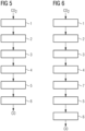
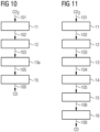
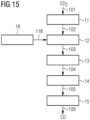
- CO 2 is fed to the first reactor 11 via the first line 101
- hydrogen carbonate produced there is fed to the second reactor 12 via the second line 102
- formate produced there is fed to the third reactor 13 via the third line 103
- amide produced there is fed to the third reactor 13 via the fourth line 104 is fed to the fourth reactor 14
- CO and amine produced there are fed via the fifth line 105 to the fifth reactor 15, and CO is removed via the CO product line 100.
- the device has the Figure 14 additionally has a second connecting device 117 between the separation device 17 and the first reactor 11.
- the CO is passed via the CO product line 100 to a Fischer-Tropsch device 19 as an exemplary further processing device for CO, which also provides heat coupling to the third reactor 13 or fourth reactor 14 via a first heat coupling device 119a and a second heat coupling device 119b, wherein the heat coupling could alternatively also be provided to the third line 103 or fourth line 104.
- a Fischer-Tropsch device 19 as an exemplary further processing device for CO, which also provides heat coupling to the third reactor 13 or fourth reactor 14 via a first heat coupling device 119a and a second heat coupling device 119b, wherein the heat coupling could alternatively also be provided to the third line 103 or fourth line 104.
- the device of Figure 17 then finally corresponds to a combination of the devices of the Figures 8, 9 , 11 and 13 to 16.
- the third reactor 13, the fourth line 104 and the fourth reactor 14 may be replaced by a combined third reactor 13a.
- the resulting ammonia is dissolved in water again and partially precipitated with CO 2 and then finally separated from the CO. This can result in a high proportion of CO (optimally pure CO) in the product gas, and a closed ammonia cycle can be established by returning to step a).
- the water released from the hydrogenation and/or the decomposition to formamide can be fed back into the cycle in step a) and/or in the water electrolysis.
- the energy for the decomposition of ammonium formate is taken from the waste heat of the hydrogen electrolyzer.
- the typical energy efficiency is 90% or less ( M. Schalenbach, G. Tjarks, M. Carmo, W. Lueke, M. Mueller, and D. Stolten, J. Electrochem. Soc., 163 (2016 ) F3197). With a theoretical energy of 285.83 kJ/mol, 31.76 kJ/mol of waste heat would be generated.
- H 2 O (l) ⁇ 1 ⁇ 2 O 2 (g) + H 2 (g), ⁇ H R 285.83 kJ/mol
- amide eg formamide
- the CO is further processed into fuels or other higher-value chemicals, for example, the waste heat required for the decomposition of the formamide is generated at the same location, ie the decomposition and processing sequences also fit together locally.
- the resulting amine is liquid at ambient temperature or can be dissolved in water. This ensures easy return transport. Due to easy transport, the processes of CO2 absorption, hydrogenation and release can also be spatially separated without the need to transport critical gases.
- the system consisting of the components shown in Table 2 was calculated using the ENRTL-RK material property method. Pure gas phase systems were calculated using the Soave-Redlich-Kwong (SRK) method (methods available in the integrated databases).
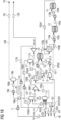
- the flow sheet consists of the process steps a) to f) as well as the heat integration of the product stream and the Fischer-Tropsch plant (119a, 119b). The purification of carbon monoxide in a cold box is also part of the flow sheet and thus part of the energy balance.
- the product comprising CO 106a contains a larger proportion of ammonia, which is separated for further use of the product CO in the process chain. This is done via a cryogenic process in cold boxes 16a,b.
- the cooled ammonia is first preheated by the heat exchanger E and then fed back to step a) in the first reactor 11), thereby ensuring a closed ammonia cycle.
- the first feedback device R2 and the stream NH3 are not connected to each other.
- step a) the water content is kept as low as possible (25.6 wt.% ammonia, 36.2 wt.% CO 2 , remainder water) in order to keep the energy consumption of the subsequent processes low.
- step a) corresponds in principle to a conventional amine wash, although in the calculated process example the water and CO 2 content in the first step a) differs from the amine wash. In conventional amine scrubbing, the CO 2 and ammonia loadings are significantly smaller and thus the water content is larger.
- the product mixture consists of 5.6 m 3 /day of an aqueous phase and 17.3 m 3 /day of a solid phase (mostly ammonium hydrogen carbonate).
- This requires a reaction apparatus that is suitable for a pasty and abrasive product mixture, therefore more continuous crystallizers with gas introduction stirrers can be used as the first reactor 11.
- Rotating positive displacement pumps such as eccentric screw pumps such as pump P are suitable for conveying the resulting paste-like mixture.
- step b the process step is carried out in a slurry reactor with a highly dispersed palladium catalyst.
- the reaction enthalpy of the exothermic hydrogenation is -21.359 kJ/mol.
- the heat removal from the reactor, which is necessary on a larger scale, can be used for preheating the next step c).
- the process conditions for hydrogenation in the slurry reactor are set at 60 °C and 27.5 bar for the simulation. In addition to the electrochemical compression of the hydrogen, it must therefore be further compressed and then brought to the reaction temperature of the second step.
- the energy required for the isentropic compression in compressor D at an efficiency of 72% and the required cooling (C2) is a total of 0.1 MW.
- the water produced in process step b) can be used as an internal heat transfer medium to heat the entire process through back integration (process streams from 105a1) and is only separated later in the process (SPLIT1) to avoid an accumulation of byproducts.
- SPLIT1 back integration
- purifying the purge stream 120, which contains byproducts an almost complete recovery of the ammonia used in the process is possible.
- the purified water can be fed to the electrolyzer both as process water (stream H 2 O) and, if necessary, after removal of the ionic components.
- the reaction step c) in the third reactor 13 is highly endothermic with a reaction enthalpy of 94.6 kJ/mol, which is why it can be assumed that in addition to the preheating to an operating temperature of 140 °C in or after step b), the reactor itself represents a large heat sink. These sinks can be compensated by the back integration of the product stream (preheating with the second heat exchanger HR1) and the integration of the waste heat from the Fischer-Tropsch process via the first heat coupling device 119a.
- the reaction step c) takes place in the liquid phase, but the gases dissolved in the water in step a) are expelled when the reaction mixture is heated.
- a reaction pressure of 1 bar a large part of the water involved in the process is in the gas phase. For this reason, The reason is that a possible reactor configuration is a tubular reactor packed with catalyst or a tube bundle reactor.
- the water produced in the previous reaction step or the absorbent from step a) can be separated by distillation using the waste heat from the Fischer-Tropsch process before preheating the reaction mixture. This enables smaller mass flows in steps c) and d) and the subsequent purification sequence, but makes it more difficult to convey the reaction mixture, which is partially present as a solid.
- step d the gas phase was analyzed during initial decomposition tests of formamide.
- the measuring setup was previously flushed with nitrogen.
- Formamide was heated to 220°C until regular bubble formation occurred. Ammonia and possibly HCN were separated.
- Table 3 Gas analysis results for step d) [Vol.%] CO 83.0% H2 0.06% CO2 0.21% N2 11.1% O2 0.33% In total 94.7% CO: H2 1376
- the phase consisting largely of water can be separated in the separation device 17.
- the product stream is only cooled from 84°C to 68°C.
- the gas product stream 105b2 which contains the product gas, then passes into the fifth reactor 15, in which case the ammonia is washed out with CO 2.
- the result is a purified product stream which contains a smaller proportion of NH 3.
- the NH 3 remaining in the product stream is separated in cold boxes 16a,b by the cryogenic step f) preceding the Fischer-Tropsch synthesis and heated to 30 °C via a preheating device in order to be reused in step a). This closes the ammonia cycle of the process.
- the purge stream 120 is purified and fed back in as a process water stream an almost complete regeneration of the ammonia is possible.
- Step e) in the fifth reactor 15 also represents a type of ammonia scrubbing, in this case with the aim of enriching the product gas with CO and precipitating NH 3 as far as possible. This enables lower energy expenditure for the downstream highly selective CO purification in cold boxes 16a,b before the Fischer-Tropsch synthesis.
- Step e) is carried out at a temperature level of 30 - 60 °C and a pressure level of 1 bar, since low temperatures lead to a higher yield of ammonium carbonate and thus a more efficient separation process.
- the energy balance of the process is considered, taking into account only the Figure 18
- the potentially recirculating streams 120 and R2 are not taken into account.
- the purge stream 120 can be evaporated by distillation using the waste heat from the Fischer-Tropsch process, whereby salts with a low water content can be recycled into the process. For simulation-technical reasons, this step is not included in Figure 18 of the process simulation.
- the process simulation was carried out for a hydrogen mass flow of 1.3 t/day, which corresponds to an electrolysis capacity of 13.1 MW.
- the CO production capacity of the process is 15.1 t/day with a purity of 94.1% (5.8% hydrogen, 555 ppm NH 3 ).
- the input flows of the process are 9 t/day of water and 6.1 t/day of ammonia.
- step a an equilibrium is assumed and the product flows are calculated accordingly.
- the conversion in reaction step b) is estimated on the basis of the literature (see above) to be 80% with regard to ammonium hydrogen carbonate.
- step c) a conversion of 95% with regard to the formate is assumed.
- reaction step d due to the decomposition reaction Full conversion is assumed in the evaporation boiler. 3.7 t/day of the ammonia used can be directly returned in gaseous form.
- the recirculated ammonia stream R2 from cold boxes 16a,b also contains 1.2 t/day of ammonium ions and 3.9 t/day of carbamate ions. Converted to the amount of ammonia returned, 82% of the ammonia used can be recycled. Accordingly, 18% is in the purge stream 120, which can also be purified and fed into the water electrolysis as process water.
- the yield of CO in relation to the CO 2 used in the process shown is 89%.
- the remaining CO 2 is eliminated in the form of chemically or physically dissolved species via the purge stream 120.
- the purification of this stream is possible as already mentioned.
- the present process is based on the combination of production steps that have already been industrialized/industrialized but are used completely independently from a chemical point of view.
- DMF dimethylformamide
- Step e Purification of CO via a kind of "inverse" amine wash
Landscapes
- Chemical & Material Sciences (AREA)
- Organic Chemistry (AREA)
- Inorganic Chemistry (AREA)
- Chemical Kinetics & Catalysis (AREA)
- Organic Low-Molecular-Weight Compounds And Preparation Thereof (AREA)
Claims (15)
- Procédé de production de CO à partir de CO2, comprenant,a) réaction de CO2 sur de l'eau et une amine de formule HNR1R2, dans laquelle R1 et R2 sont les mêmes ou sont différents et sont choisis parmi l'hydrogène et des radicaux alcoyles substitués et non substitués ayant de 1 à 20 atomes de C, pour donner un bicarbonate de formule HNR1R2H+ HCO3 - ;b) réaction du bicarbonate de formule HNR1R2H+ HCO3 - sur l'hydrogène pour donner un formiate de formule HNR1R2H+ HCO2 - ;c) décomposition du formiate de formule HNR1R2H+ HCO2 - en un amide de formule HCONR1R2 et en H2O ;d) décomposition de l'amide de formule HCONR1R2 en du CO et en une amine de formule HNR1R2, un mélange comprenant l'amine de formule HNR1R2 et du CO étant créé ; ete) réaction au moins partielle de l'amine de formule HNR1R2 du mélange comprenant l'amine de formule HNR1R2 et du CO sur un réactif de précipitation, de préférence sur du CO2, pour la production d'un mélange comprenant du CO, un produit de précipitation de la réaction de l'amine de formule HNR1R2 sur le réactif de précipitation et, le cas échéant, de l'amine n'ayant pas réagi de formule HNR1R2, de préférence un mélange comprenant du CO, un bicarbonate de formule HNR1R2H+ HCO3 - et, le cas échéant, de l'amine n'ayant pas réagi de formule HNR1R2 et séparation du produit de précipitation de la réaction de l'amine de formule HNR1R2 sur le réactif de précipitation, de préférence du bicarbonate de formule HNR1R2H+ HCO3 -, un produit comprenant du CO et, le cas échéant, de l'amine n'ayant pas réagi de formule HNR1R2 étant créé.
- Procédé suivant la revendication 1, dans lequel le produit comprenant du CO et, le cas échéant, de l'amine n'ayant pas réagi de formule HNR1R2 comprend l'amine n'ayant pas réagi de formule HNR1R2, comprenant en outre un stade f) de séparation du CO du produit comprenant du CO et de l'amine n'ayant pas réagi de formule HNR1R2.
- Procédé suivant la revendication 1 ou 2, dans lequel le réactif de précipitation dans le stade e) est du CO2, dans lequel on envoie, au stade b), le bicarbonate de formule HNR1R2H+ HCO3 -formé au stade e) .
- Procédé suivant l'une des revendications précédentes, dans lequel on effectue les stades a) à d) dans un solvant.
- Procédé suivant la revendication 4, dans lequel on sépare le solvant au moins en partie avant le stade e), de préférence entre le stade d) et le stade e).
- Procédé suivant la revendication 5, dans lequel on envoie du solvant séparé avant le stade e) et/ou de l'eau de la réaction dans le stade b) et/ou c) au moins en partie à nouveau au stade a) et/ou dans le cas de l'eau, le cas échéant, à une électrolyse de l'eau.
- Procédé suivant l'une des revendications précédentes, dans lequel R1 et R2 sont de l'hydrogène.
- Procédé suivant l'une des revendications précédentes, dans lequel on produit l'hydrogène utilisé au stade b) par une électrolyse de l'eau que l'on fait fonctionner, de préférence par des énergies renouvelables.
- Procédé suivant l'une des revendications précédentes, dans lequel, dans le stade c) et/ou d), on met de l'énergie à disposition par une autre réaction du CO, de préférence, par une autre réaction du CO dans une synthèse de Fischer Tropsch.
- Installation de production de CO à partir de CO2, comprenant :- un premier réacteur (11) de réaction de CO2 sur de l'H2O et une amine de formule HNR1R2, dans laquelle R1 et R2 sont les mêmes ou sont différents et sont choisis parmi l'hydrogène et des radicaux alcoyles substitués et non substitués ayant de 1 à 20 atomes de C, pour donner un bicarbonate de formule HNR1R2H+ HCO3 -, qui est constitué pour faire réagir du CO2 sur de l'H2O et une amine de formule HNR1R2 ;- un deuxième réacteur (12) de réaction du bicarbonate de formule HNR1R2H+ HCO3 - sur l'hydrogène pour donner un formiate de formule HNR1R2H+ HCO2 -, qui est constitué pour faire réagir le bicarbonate de formule HNR1R2H+ HCO3 - sur l'hydrogène pour donner un formiate de formule HNR1R2H+ HCO2 - ; comprenant en outre- un troisième réacteur (13) de décomposition du formiate de formule HNR1R2H+ HCO2 - en de l'H2O et en un amide de formule HCONR1R2, qui est constitué pour décomposer le formiate de formule HNR1R2H+ HCO2 - en H2O et en un amide de formule HCONR1R2, et- un quatrième réacteur (14) de décomposition de l'amide de formule HCONR1R2 en du CO et en une amine de formule HNR1R2, qui est constitué pour décomposer l'amide de formule HCONR1R2 en du CO et en une amine de formule HNR1R2 ; ou- un troisième réacteur (13a) combiné de décomposition du formiate de formule HNR1R2H+ HCO2 - en de l'H2O, du CO et une amine de formule HNR1R2, qui est constitué pour décomposer le formiate de formule HNR1R2H+ HCO2 - en H2O, CO et une amine de formule HNR1R2 ; comprenant en outre- un cinquième réacteur (15) de réaction au moins partielle de l'amine de formule HNR1R2 produite dans le troisième réacteur (13a) combiné ou dans le quatrième réacteur (14) sur un réactif de précipitation, de préférence sur du CO2, pour la production d'un mélange comprenant du CO, un produit de précipitation de la réaction de l'amine de formule HNR1R2 sur le réactif de précipitation et, le cas échéant, de l'amine n'ayant pas réagi de formule HNR1R2, de préférence un mélange comprenant du CO, un bicarbonate de formule HNR1R2H+ HCO3 - et, le cas échéant, de l'amine n'ayant pas réagi de formule HNR1R2, et de séparation du produit de précipitation de la réaction de l'amine de formule HNR1R2 sur le réactif de précipitation, de préférence du bicarbonate de formule HNR1R2H+ HCO3 -, un produit comprenant du CO et, le cas échéant, de l'amine n'ayant pas réagi de formule HNR1R2 étant créé, dans laquelle le cinquième réacteur (15) est constitué en outre pour mettre en réaction, au moins en partie, l'amine de formule HNR1R2, produite dans le troisième réacteur (13a) combiné ou dans le quatrième réacteur (14), sur un réactif de précipitation, de préférence sur du CO2, dans laquelle on produit un mélange comprenant du CO, un produit de précipitation de la réaction de l'amine de formule HNR1R2 sur le réactif de précipitation et, le cas échéant, de l'amine n'ayant pas réagi de formule HNR1R2, de préférence du mélange comprenant du CO, un bicarbonate de formule HNR1R2H+ HCO3 - et, le cas échéant, de l'amine n'ayant pas réagi de formule HNR1R2, et dans laquelle le cinquième réacteur (15) est constitué en outre pour séparer le produit de précipitation de la réaction de l'amine de formule HNR1R2 sur le réactif de précipitation, de préférence le bicarbonate de formule HNR1R2H+ HCO3 -.
- Installation suivant la revendication 10, dans laquelle il est créé un produit comprenant du CO et de l'amine n'ayant pas réagi de formule HNR1R2, comprenant en outre un sixième réacteur (16) de séparation du CO du produit comprenant du CO et de l'amine n'ayant pas réagi de formule HNR1R2, qui est constitué pour séparer du CO du produit comprenant du CO et de l'amine n'ayant pas réagi de formule HNR1R2.
- Installation suivant la revendication 10 ou 11, dans laquelle, dans le cinquième réacteur (15), on forme le bicarbonate de formule HNR1R2H+ HCO3 -, comprenant en outre un dispositif (115) de communication entre le cinquième réacteur (15) et le deuxième réacteur (12) pour envoyer le bicarbonate de formule HNR1R2H+ HCO3 -formé dans le cinquième réacteur (15) du cinquième réacteur (15) au deuxième réacteur (12), qui est constitué pour envoyer du bicarbonate de formule HNR1R2H+ HCO3 - formé dans le cinquième réacteur (15) du cinquième réacteur (15) au deuxième réacteur (12) .
- Installation suivant l'une des revendications 10 à 12, comprenant en outre une installation (17) de séparation, qui est disposée dans le sens du courant entre le quatrième réacteur (14) et le cinquième réacteur (15) et qui est constituée pour séparer au moins en partie un solvant et/ou de l'eau du CO et de l'amine de formule HNR1R2.
- Installation suivant la revendication 13, comprenant en outre un deuxième dispositif (117) de communication entre l'installation (17) de séparation et le premier réacteur (11), qui est constitué pour envoyer au premier réacteur (11) du solvant séparé dans l'installation (17) de séparation.
- Installation suivant l'une des revendications 10 à 14, comprenant en outre un dispositif (18) d'électrolyse de l'eau, qui est constitué pour électrolyser de l'eau et pour disposer d'hydrogène dans le deuxième réacteur (12).
Applications Claiming Priority (3)
| Application Number | Priority Date | Filing Date | Title |
|---|---|---|---|
| DE102020208634 | 2020-07-09 | ||
| DE102020212022.6A DE102020212022A1 (de) | 2020-07-09 | 2020-09-24 | Verfahren und Vorrichtung zur Herstellung von Kohlenmonoxid aus Kohlendioxid |
| PCT/EP2021/061823 WO2022008117A1 (fr) | 2020-07-09 | 2021-05-05 | Procédé et dispositif permettant la production de monoxyde de carbone à partir de dioxyde de carbone |
Publications (2)
| Publication Number | Publication Date |
|---|---|
| EP4132880A1 EP4132880A1 (fr) | 2023-02-15 |
| EP4132880B1 true EP4132880B1 (fr) | 2024-07-03 |
Family
ID=79020132
Family Applications (1)
| Application Number | Title | Priority Date | Filing Date |
|---|---|---|---|
| EP21728005.6A Active EP4132880B1 (fr) | 2020-07-09 | 2021-05-05 | Procédé et dispositif permettant la production de monoxyde de carbone à partir de dioxyde de carbone |
Country Status (9)
| Country | Link |
|---|---|
| US (1) | US20230278875A1 (fr) |
| EP (1) | EP4132880B1 (fr) |
| CN (1) | CN115776970B (fr) |
| DE (1) | DE102020212022A1 (fr) |
| DK (1) | DK4132880T3 (fr) |
| ES (1) | ES2991880T3 (fr) |
| FI (1) | FI4132880T3 (fr) |
| PT (1) | PT4132880T (fr) |
| WO (1) | WO2022008117A1 (fr) |
Families Citing this family (2)
| Publication number | Priority date | Publication date | Assignee | Title |
|---|---|---|---|---|
| US20230265569A1 (en) * | 2022-02-21 | 2023-08-24 | Xerox Corporation | Amine-functionalized silver nanoparticles for gas diffusion electrodes |
| DE102024205409A1 (de) | 2024-02-08 | 2025-08-14 | Friedrich-Alexander-Universität Erlangen-Nürnberg, in Vertretung des Freistaates Bayern | Verfahren zum Herstellen von Kohlenmonoxid und Verfahren zum Herstellen eines synthetischen Kraftstoffs |
Family Cites Families (10)
| Publication number | Priority date | Publication date | Assignee | Title |
|---|---|---|---|---|
| US1582675A (en) | 1925-04-03 | 1926-04-27 | Basf Ag | Production of formamid |
| EP0597151A1 (fr) * | 1992-11-10 | 1994-05-18 | Universiteit Twente | Procédé de préparation de l'acide formique |
| CN101687725A (zh) | 2007-05-14 | 2010-03-31 | Grt公司 | 使烃类原料转化同时电解回收卤素的方法 |
| US9012345B2 (en) | 2010-03-26 | 2015-04-21 | Dioxide Materials, Inc. | Electrocatalysts for carbon dioxide conversion |
| US8562811B2 (en) | 2011-03-09 | 2013-10-22 | Liquid Light, Inc. | Process for making formic acid |
| CN104822861B (zh) | 2012-09-24 | 2017-03-08 | 二氧化碳材料公司 | 用于将二氧化碳转化为有用燃料和化学品的装置和方法 |
| EP2813470A1 (fr) * | 2013-06-14 | 2014-12-17 | Bayer Technology Services GmbH | Procédé de décomposition d'acide formique utilisant des catalyseurs de zéolite |
| KR20170127416A (ko) | 2015-01-12 | 2017-11-21 | 유니버시티 오브 써던 캘리포니아 | 고체 담체 상의 개질 아민의 재생성 흡착제 |
| KR101921190B1 (ko) | 2017-01-18 | 2018-11-23 | 효성화학 주식회사 | 알칸의 탈수소화 방법 |
| US10975477B2 (en) | 2017-10-02 | 2021-04-13 | Battelle Energy Alliance, Llc | Methods and systems for the electrochemical reduction of carbon dioxide using switchable polarity materials |
-
2020
- 2020-09-24 DE DE102020212022.6A patent/DE102020212022A1/de not_active Withdrawn
-
2021
- 2021-05-05 EP EP21728005.6A patent/EP4132880B1/fr active Active
- 2021-05-05 ES ES21728005T patent/ES2991880T3/es active Active
- 2021-05-05 PT PT217280056T patent/PT4132880T/pt unknown
- 2021-05-05 US US18/012,396 patent/US20230278875A1/en active Pending
- 2021-05-05 DK DK21728005.6T patent/DK4132880T3/da active
- 2021-05-05 FI FIEP21728005.6T patent/FI4132880T3/fi active
- 2021-05-05 CN CN202180048694.4A patent/CN115776970B/zh active Active
- 2021-05-05 WO PCT/EP2021/061823 patent/WO2022008117A1/fr not_active Ceased
Also Published As
| Publication number | Publication date |
|---|---|
| US20230278875A1 (en) | 2023-09-07 |
| CA3186162A1 (fr) | 2022-01-13 |
| DK4132880T3 (da) | 2024-09-16 |
| WO2022008117A1 (fr) | 2022-01-13 |
| CN115776970B (zh) | 2024-11-12 |
| CN115776970A (zh) | 2023-03-10 |
| EP4132880A1 (fr) | 2023-02-15 |
| ES2991880T3 (es) | 2024-12-05 |
| FI4132880T3 (fi) | 2024-09-16 |
| DE102020212022A1 (de) | 2022-01-13 |
| PT4132880T (pt) | 2024-09-16 |
Similar Documents
| Publication | Publication Date | Title |
|---|---|---|
| DE3405217C2 (fr) | ||
| DE69906893T2 (de) | Verfahren zur Hydrierung von Dinitrotoluol zu Toluenediamin mittels eines monolithischen Katalysators | |
| DE2549439C2 (fr) | ||
| EP3488028B1 (fr) | Procédé de production d'ammoniac par voie électrochimique | |
| EP4031640B1 (fr) | Installation et procédé de fabrication de combustibles synthétiques sans eau douce | |
| EP3055058A1 (fr) | Procédé et dispositif de conversion de substances avec catalyse assistée par plasma | |
| DE2542935C2 (de) | Verfahren zur Herstellung von Schwefelsäure aus Schefeldioxid | |
| EP4324815A1 (fr) | Procédé et installation de production de méthanol et de gaz de synthèse | |
| EP0634386A1 (fr) | Procédé de préparation du carbonate de diméthyle | |
| EP2148855A1 (fr) | Procédé de production en continu de méthylmercaptan à partir de composés contenant du carbone et de l'hydrogène | |
| DE2855231C3 (de) | Kontinuierliches Verfahren zur Herstellung von Glykolen | |
| DE102020212022A1 (de) | Verfahren und Vorrichtung zur Herstellung von Kohlenmonoxid aus Kohlendioxid | |
| DE102011016759A1 (de) | Verfahren zur Herstellung von NH3 | |
| EP1310172B1 (fr) | Procédé de préparation de mélanges de formate de métal et d'acide formique | |
| EP2986562B1 (fr) | Procédé de traitement d'eaux usées issues de la fabrication de nitrobenzène | |
| WO2021089183A1 (fr) | Procédé et installation de production de monoéthylène glycol | |
| EP2448892B1 (fr) | Procédé de production de n-butane peu odorant | |
| CN110172029B (zh) | 一种连续合成2-氨基-2-甲基-1-丙醇的方法 | |
| WO2024208940A2 (fr) | Production durable de diisocyanate d'hexaméthylène pour la production de polyuréthane | |
| EP2838875B1 (fr) | Procédé de départ amélioré de la réaction lors de la fabrication d'amines aromatiques à partir de nitro-aromates | |
| EP3142996B1 (fr) | Procédé de fabrication de toluylènediamine | |
| CA3186162C (fr) | Procede et dispositif permettant la production de monoxyde de carbone a partir de dioxyde de carbone | |
| DE102021006375A1 (de) | Verfahren zur kontinuierlichen Herstellung von Methanol | |
| CN217809226U (zh) | 一种合成二甲基砜的装置 | |
| DE2519383B2 (de) | Verfahren zur Reinigung und Wiedergewinnung von Alkalimetallalkylamiden aus einer Lösung |
Legal Events
| Date | Code | Title | Description |
|---|---|---|---|
| STAA | Information on the status of an ep patent application or granted ep patent |
Free format text: STATUS: UNKNOWN |
|
| STAA | Information on the status of an ep patent application or granted ep patent |
Free format text: STATUS: THE INTERNATIONAL PUBLICATION HAS BEEN MADE |
|
| PUAI | Public reference made under article 153(3) epc to a published international application that has entered the european phase |
Free format text: ORIGINAL CODE: 0009012 |
|
| STAA | Information on the status of an ep patent application or granted ep patent |
Free format text: STATUS: REQUEST FOR EXAMINATION WAS MADE |
|
| 17P | Request for examination filed |
Effective date: 20221110 |
|
| AK | Designated contracting states |
Kind code of ref document: A1 Designated state(s): AL AT BE BG CH CY CZ DE DK EE ES FI FR GB GR HR HU IE IS IT LI LT LU LV MC MK MT NL NO PL PT RO RS SE SI SK SM TR |
|
| RAP3 | Party data changed (applicant data changed or rights of an application transferred) |
Owner name: SIEMENS ENERGY GLOBAL GMBH & CO. KG |
|
| DAV | Request for validation of the european patent (deleted) | ||
| DAX | Request for extension of the european patent (deleted) | ||
| GRAP | Despatch of communication of intention to grant a patent |
Free format text: ORIGINAL CODE: EPIDOSNIGR1 |
|
| STAA | Information on the status of an ep patent application or granted ep patent |
Free format text: STATUS: GRANT OF PATENT IS INTENDED |
|
| INTG | Intention to grant announced |
Effective date: 20240226 |
|
| GRAS | Grant fee paid |
Free format text: ORIGINAL CODE: EPIDOSNIGR3 |
|
| GRAA | (expected) grant |
Free format text: ORIGINAL CODE: 0009210 |
|
| STAA | Information on the status of an ep patent application or granted ep patent |
Free format text: STATUS: THE PATENT HAS BEEN GRANTED |
|
| AK | Designated contracting states |
Kind code of ref document: B1 Designated state(s): AL AT BE BG CH CY CZ DE DK EE ES FI FR GB GR HR HU IE IS IT LI LT LU LV MC MK MT NL NO PL PT RO RS SE SI SK SM TR |
|
| REG | Reference to a national code |
Ref country code: CH Ref legal event code: EP |
|
| REG | Reference to a national code |
Ref country code: DE Ref legal event code: R096 Ref document number: 502021004236 Country of ref document: DE |
|
| REG | Reference to a national code |
Ref country code: NL Ref legal event code: FP |
|
| REG | Reference to a national code |
Ref country code: FI Ref legal event code: FGE Ref country code: PT Ref legal event code: SC4A Ref document number: 4132880 Country of ref document: PT Date of ref document: 20240916 Kind code of ref document: T Free format text: AVAILABILITY OF NATIONAL TRANSLATION Effective date: 20240909 Ref country code: DK Ref legal event code: T3 Effective date: 20240911 |
|
| REG | Reference to a national code |
Ref country code: SE Ref legal event code: TRGR |
|
| REG | Reference to a national code |
Ref country code: LT Ref legal event code: MG9D |
|
| REG | Reference to a national code |
Ref country code: ES Ref legal event code: FG2A Ref document number: 2991880 Country of ref document: ES Kind code of ref document: T3 Effective date: 20241205 |
|
| PG25 | Lapsed in a contracting state [announced via postgrant information from national office to epo] |
Ref country code: GR Free format text: LAPSE BECAUSE OF FAILURE TO SUBMIT A TRANSLATION OF THE DESCRIPTION OR TO PAY THE FEE WITHIN THE PRESCRIBED TIME-LIMIT Effective date: 20241004 Ref country code: PL Free format text: LAPSE BECAUSE OF FAILURE TO SUBMIT A TRANSLATION OF THE DESCRIPTION OR TO PAY THE FEE WITHIN THE PRESCRIBED TIME-LIMIT Effective date: 20240703 |
|
| PG25 | Lapsed in a contracting state [announced via postgrant information from national office to epo] |
Ref country code: BG Free format text: LAPSE BECAUSE OF FAILURE TO SUBMIT A TRANSLATION OF THE DESCRIPTION OR TO PAY THE FEE WITHIN THE PRESCRIBED TIME-LIMIT Effective date: 20240703 |
|
| PG25 | Lapsed in a contracting state [announced via postgrant information from national office to epo] |
Ref country code: LV Free format text: LAPSE BECAUSE OF FAILURE TO SUBMIT A TRANSLATION OF THE DESCRIPTION OR TO PAY THE FEE WITHIN THE PRESCRIBED TIME-LIMIT Effective date: 20240703 |
|
| PG25 | Lapsed in a contracting state [announced via postgrant information from national office to epo] |
Ref country code: IS Free format text: LAPSE BECAUSE OF FAILURE TO SUBMIT A TRANSLATION OF THE DESCRIPTION OR TO PAY THE FEE WITHIN THE PRESCRIBED TIME-LIMIT Effective date: 20241103 |
|
| PG25 | Lapsed in a contracting state [announced via postgrant information from national office to epo] |
Ref country code: CZ Free format text: LAPSE BECAUSE OF FAILURE TO SUBMIT A TRANSLATION OF THE DESCRIPTION OR TO PAY THE FEE WITHIN THE PRESCRIBED TIME-LIMIT Effective date: 20240703 Ref country code: HR Free format text: LAPSE BECAUSE OF FAILURE TO SUBMIT A TRANSLATION OF THE DESCRIPTION OR TO PAY THE FEE WITHIN THE PRESCRIBED TIME-LIMIT Effective date: 20240703 |
|
| PG25 | Lapsed in a contracting state [announced via postgrant information from national office to epo] |
Ref country code: RS Free format text: LAPSE BECAUSE OF FAILURE TO SUBMIT A TRANSLATION OF THE DESCRIPTION OR TO PAY THE FEE WITHIN THE PRESCRIBED TIME-LIMIT Effective date: 20241003 |
|
| PG25 | Lapsed in a contracting state [announced via postgrant information from national office to epo] |
Ref country code: RS Free format text: LAPSE BECAUSE OF FAILURE TO SUBMIT A TRANSLATION OF THE DESCRIPTION OR TO PAY THE FEE WITHIN THE PRESCRIBED TIME-LIMIT Effective date: 20241003 Ref country code: PL Free format text: LAPSE BECAUSE OF FAILURE TO SUBMIT A TRANSLATION OF THE DESCRIPTION OR TO PAY THE FEE WITHIN THE PRESCRIBED TIME-LIMIT Effective date: 20240703 Ref country code: LV Free format text: LAPSE BECAUSE OF FAILURE TO SUBMIT A TRANSLATION OF THE DESCRIPTION OR TO PAY THE FEE WITHIN THE PRESCRIBED TIME-LIMIT Effective date: 20240703 Ref country code: IS Free format text: LAPSE BECAUSE OF FAILURE TO SUBMIT A TRANSLATION OF THE DESCRIPTION OR TO PAY THE FEE WITHIN THE PRESCRIBED TIME-LIMIT Effective date: 20241103 Ref country code: HR Free format text: LAPSE BECAUSE OF FAILURE TO SUBMIT A TRANSLATION OF THE DESCRIPTION OR TO PAY THE FEE WITHIN THE PRESCRIBED TIME-LIMIT Effective date: 20240703 Ref country code: GR Free format text: LAPSE BECAUSE OF FAILURE TO SUBMIT A TRANSLATION OF THE DESCRIPTION OR TO PAY THE FEE WITHIN THE PRESCRIBED TIME-LIMIT Effective date: 20241004 Ref country code: CZ Free format text: LAPSE BECAUSE OF FAILURE TO SUBMIT A TRANSLATION OF THE DESCRIPTION OR TO PAY THE FEE WITHIN THE PRESCRIBED TIME-LIMIT Effective date: 20240703 Ref country code: BG Free format text: LAPSE BECAUSE OF FAILURE TO SUBMIT A TRANSLATION OF THE DESCRIPTION OR TO PAY THE FEE WITHIN THE PRESCRIBED TIME-LIMIT Effective date: 20240703 |
|
| REG | Reference to a national code |
Ref country code: DE Ref legal event code: R097 Ref document number: 502021004236 Country of ref document: DE |
|
| PG25 | Lapsed in a contracting state [announced via postgrant information from national office to epo] |
Ref country code: SM Free format text: LAPSE BECAUSE OF FAILURE TO SUBMIT A TRANSLATION OF THE DESCRIPTION OR TO PAY THE FEE WITHIN THE PRESCRIBED TIME-LIMIT Effective date: 20240703 Ref country code: RO Free format text: LAPSE BECAUSE OF FAILURE TO SUBMIT A TRANSLATION OF THE DESCRIPTION OR TO PAY THE FEE WITHIN THE PRESCRIBED TIME-LIMIT Effective date: 20240703 |
|
| PG25 | Lapsed in a contracting state [announced via postgrant information from national office to epo] |
Ref country code: EE Free format text: LAPSE BECAUSE OF FAILURE TO SUBMIT A TRANSLATION OF THE DESCRIPTION OR TO PAY THE FEE WITHIN THE PRESCRIBED TIME-LIMIT Effective date: 20240703 |
|
| PG25 | Lapsed in a contracting state [announced via postgrant information from national office to epo] |
Ref country code: SK Free format text: LAPSE BECAUSE OF FAILURE TO SUBMIT A TRANSLATION OF THE DESCRIPTION OR TO PAY THE FEE WITHIN THE PRESCRIBED TIME-LIMIT Effective date: 20240703 Ref country code: IT Free format text: LAPSE BECAUSE OF FAILURE TO SUBMIT A TRANSLATION OF THE DESCRIPTION OR TO PAY THE FEE WITHIN THE PRESCRIBED TIME-LIMIT Effective date: 20240703 |
|
| PLBE | No opposition filed within time limit |
Free format text: ORIGINAL CODE: 0009261 |
|
| STAA | Information on the status of an ep patent application or granted ep patent |
Free format text: STATUS: NO OPPOSITION FILED WITHIN TIME LIMIT |
|
| 26N | No opposition filed |
Effective date: 20250404 |
|
| PGFP | Annual fee paid to national office [announced via postgrant information from national office to epo] |
Ref country code: AT Payment date: 20250721 Year of fee payment: 5 |
|
| REG | Reference to a national code |
Ref country code: CH Ref legal event code: H13 Free format text: ST27 STATUS EVENT CODE: U-0-0-H10-H13 (AS PROVIDED BY THE NATIONAL OFFICE) Effective date: 20251223 |
|
| PG25 | Lapsed in a contracting state [announced via postgrant information from national office to epo] |
Ref country code: LU Free format text: LAPSE BECAUSE OF NON-PAYMENT OF DUE FEES Effective date: 20250505 |
|
| PG25 | Lapsed in a contracting state [announced via postgrant information from national office to epo] |
Ref country code: CH Free format text: LAPSE BECAUSE OF NON-PAYMENT OF DUE FEES Effective date: 20250531 |
|
| PG25 | Lapsed in a contracting state [announced via postgrant information from national office to epo] |
Ref country code: MC Free format text: LAPSE BECAUSE OF FAILURE TO SUBMIT A TRANSLATION OF THE DESCRIPTION OR TO PAY THE FEE WITHIN THE PRESCRIBED TIME-LIMIT Effective date: 20240703 |
|
| PGFP | Annual fee paid to national office [announced via postgrant information from national office to epo] |
Ref country code: GB Payment date: 20260323 Year of fee payment: 6 |
|
| PG25 | Lapsed in a contracting state [announced via postgrant information from national office to epo] |
Ref country code: IE Free format text: LAPSE BECAUSE OF NON-PAYMENT OF DUE FEES Effective date: 20250505 |
|
| PGFP | Annual fee paid to national office [announced via postgrant information from national office to epo] |
Ref country code: NL Payment date: 20260519 Year of fee payment: 6 |
|
| PG25 | Lapsed in a contracting state [announced via postgrant information from national office to epo] |
Ref country code: LT Free format text: LAPSE BECAUSE OF FAILURE TO SUBMIT A TRANSLATION OF THE DESCRIPTION OR TO PAY THE FEE WITHIN THE PRESCRIBED TIME-LIMIT Effective date: 20240703 |
|
| PGFP | Annual fee paid to national office [announced via postgrant information from national office to epo] |
Ref country code: ES Payment date: 20260609 Year of fee payment: 6 |
|
| PGFP | Annual fee paid to national office [announced via postgrant information from national office to epo] |
Ref country code: DK Payment date: 20260520 Year of fee payment: 6 |
|
| PGFP | Annual fee paid to national office [announced via postgrant information from national office to epo] |
Ref country code: DE Payment date: 20260522 Year of fee payment: 6 |
|
| PGFP | Annual fee paid to national office [announced via postgrant information from national office to epo] |
Ref country code: NO Payment date: 20260519 Year of fee payment: 6 |
|
| PGFP | Annual fee paid to national office [announced via postgrant information from national office to epo] |
Ref country code: SE Payment date: 20260520 Year of fee payment: 6 Ref country code: FI Payment date: 20260519 Year of fee payment: 6 |
|
| PGFP | Annual fee paid to national office [announced via postgrant information from national office to epo] |
Ref country code: BE Payment date: 20260518 Year of fee payment: 6 |
|
| PGFP | Annual fee paid to national office [announced via postgrant information from national office to epo] |
Ref country code: PT Payment date: 20260414 Year of fee payment: 6 |
|
| PGFP | Annual fee paid to national office [announced via postgrant information from national office to epo] |
Ref country code: FR Payment date: 20260522 Year of fee payment: 6 |
|
| PG25 | Lapsed in a contracting state [announced via postgrant information from national office to epo] |
Ref country code: CY Free format text: LAPSE BECAUSE OF FAILURE TO SUBMIT A TRANSLATION OF THE DESCRIPTION OR TO PAY THE FEE WITHIN THE PRESCRIBED TIME-LIMIT Effective date: 20240703 |