EP4133335B1 - Système de mesure différentielle - Google Patents
Système de mesure différentielle Download PDFInfo
- Publication number
- EP4133335B1 EP4133335B1 EP21709440.8A EP21709440A EP4133335B1 EP 4133335 B1 EP4133335 B1 EP 4133335B1 EP 21709440 A EP21709440 A EP 21709440A EP 4133335 B1 EP4133335 B1 EP 4133335B1
- Authority
- EP
- European Patent Office
- Prior art keywords
- pattern
- target
- flow rate
- difference
- component
- Prior art date
- Legal status (The legal status is an assumption and is not a legal conclusion. Google has not performed a legal analysis and makes no representation as to the accuracy of the status listed.)
- Active
Links
Images




Classifications
-
- G—PHYSICS
- G03—PHOTOGRAPHY; CINEMATOGRAPHY; ANALOGOUS TECHNIQUES USING WAVES OTHER THAN OPTICAL WAVES; ELECTROGRAPHY; HOLOGRAPHY
- G03F—PHOTOMECHANICAL PRODUCTION OF TEXTURED OR PATTERNED SURFACES, e.g. FOR PRINTING, FOR PROCESSING OF SEMICONDUCTOR DEVICES; MATERIALS THEREFOR; ORIGINALS THEREFOR; APPARATUS SPECIALLY ADAPTED THEREFOR
- G03F7/00—Photomechanical, e.g. photolithographic, production of textured or patterned surfaces, e.g. printing surfaces; Materials therefor, e.g. comprising photoresists; Apparatus specially adapted therefor
- G03F7/70—Microphotolithographic exposure; Apparatus therefor
- G03F7/708—Construction of apparatus, e.g. environment aspects, hygiene aspects or materials
- G03F7/7085—Detection arrangement, e.g. detectors of apparatus alignment possibly mounted on wafers, exposure dose, photo-cleaning flux, stray light, thermal load
-
- G—PHYSICS
- G01—MEASURING; TESTING
- G01F—MEASURING VOLUME, VOLUME FLOW, MASS FLOW OR LIQUID LEVEL; METERING BY VOLUME
- G01F1/00—Measuring the volume flow or mass flow of fluid or fluent solid material wherein the fluid passes through a meter in a continuous flow
- G01F1/05—Measuring the volume flow or mass flow of fluid or fluent solid material wherein the fluid passes through a meter in a continuous flow by using mechanical effects
- G01F1/06—Measuring the volume flow or mass flow of fluid or fluent solid material wherein the fluid passes through a meter in a continuous flow by using mechanical effects using rotating vanes with tangential admission
- G01F1/065—Measuring the volume flow or mass flow of fluid or fluent solid material wherein the fluid passes through a meter in a continuous flow by using mechanical effects using rotating vanes with tangential admission with radiation as transfer means to the indicating device, e.g. light transmission
-
- G—PHYSICS
- G01—MEASURING; TESTING
- G01F—MEASURING VOLUME, VOLUME FLOW, MASS FLOW OR LIQUID LEVEL; METERING BY VOLUME
- G01F1/00—Measuring the volume flow or mass flow of fluid or fluent solid material wherein the fluid passes through a meter in a continuous flow
- G01F1/76—Devices for measuring mass flow of a fluid or a fluent solid material
- G01F1/86—Indirect mass flowmeters, e.g. measuring volume flow and density, temperature or pressure
-
- G—PHYSICS
- G01—MEASURING; TESTING
- G01M—TESTING STATIC OR DYNAMIC BALANCE OF MACHINES OR STRUCTURES; TESTING OF STRUCTURES OR APPARATUS, NOT OTHERWISE PROVIDED FOR
- G01M3/00—Investigating fluid-tightness of structures
- G01M3/02—Investigating fluid-tightness of structures by using fluid or vacuum
- G01M3/26—Investigating fluid-tightness of structures by using fluid or vacuum by measuring rate of loss or gain of fluid, e.g. by pressure-responsive devices, by flow detectors
- G01M3/32—Investigating fluid-tightness of structures by using fluid or vacuum by measuring rate of loss or gain of fluid, e.g. by pressure-responsive devices, by flow detectors for containers, e.g. radiators
- G01M3/3236—Investigating fluid-tightness of structures by using fluid or vacuum by measuring rate of loss or gain of fluid, e.g. by pressure-responsive devices, by flow detectors for containers, e.g. radiators by monitoring the interior space of the containers
- G01M3/3254—Investigating fluid-tightness of structures by using fluid or vacuum by measuring rate of loss or gain of fluid, e.g. by pressure-responsive devices, by flow detectors for containers, e.g. radiators by monitoring the interior space of the containers using a flow detector
-
- G—PHYSICS
- G01—MEASURING; TESTING
- G01M—TESTING STATIC OR DYNAMIC BALANCE OF MACHINES OR STRUCTURES; TESTING OF STRUCTURES OR APPARATUS, NOT OTHERWISE PROVIDED FOR
- G01M3/00—Investigating fluid-tightness of structures
- G01M3/38—Investigating fluid-tightness of structures by using light
-
- G—PHYSICS
- G03—PHOTOGRAPHY; CINEMATOGRAPHY; ANALOGOUS TECHNIQUES USING WAVES OTHER THAN OPTICAL WAVES; ELECTROGRAPHY; HOLOGRAPHY
- G03F—PHOTOMECHANICAL PRODUCTION OF TEXTURED OR PATTERNED SURFACES, e.g. FOR PRINTING, FOR PROCESSING OF SEMICONDUCTOR DEVICES; MATERIALS THEREFOR; ORIGINALS THEREFOR; APPARATUS SPECIALLY ADAPTED THEREFOR
- G03F7/00—Photomechanical, e.g. photolithographic, production of textured or patterned surfaces, e.g. printing surfaces; Materials therefor, e.g. comprising photoresists; Apparatus specially adapted therefor
- G03F7/70—Microphotolithographic exposure; Apparatus therefor
- G03F7/708—Construction of apparatus, e.g. environment aspects, hygiene aspects or materials
- G03F7/70908—Hygiene, e.g. preventing apparatus pollution, mitigating effect of pollution or removing pollutants from apparatus
-
- G—PHYSICS
- G03—PHOTOGRAPHY; CINEMATOGRAPHY; ANALOGOUS TECHNIQUES USING WAVES OTHER THAN OPTICAL WAVES; ELECTROGRAPHY; HOLOGRAPHY
- G03F—PHOTOMECHANICAL PRODUCTION OF TEXTURED OR PATTERNED SURFACES, e.g. FOR PRINTING, FOR PROCESSING OF SEMICONDUCTOR DEVICES; MATERIALS THEREFOR; ORIGINALS THEREFOR; APPARATUS SPECIALLY ADAPTED THEREFOR
- G03F7/00—Photomechanical, e.g. photolithographic, production of textured or patterned surfaces, e.g. printing surfaces; Materials therefor, e.g. comprising photoresists; Apparatus specially adapted therefor
- G03F7/70—Microphotolithographic exposure; Apparatus therefor
- G03F7/708—Construction of apparatus, e.g. environment aspects, hygiene aspects or materials
- G03F7/70975—Assembly, maintenance, transport or storage of apparatus
Definitions
- the present invention relates to systems and methods for measuring a property of targets, in particular for measuring differences in a property between two targets.
- a particular embodiment relates to a system and method for differential flow measurement in a lithographic apparatus.
- a lithographic apparatus is a machine constructed to apply a desired pattern onto a substrate.
- a lithographic apparatus can be used, for example, in the manufacture of integrated circuits (ICs).
- a lithographic apparatus may, for example, project a pattern (also often referred to as "design layout" or "design") at a patterning device (e.g., a mask) onto a layer of radiation-sensitive material (resist) provided on a substrate (e.g., a wafer).
- a lithographic apparatus may use electromagnetic radiation.
- the wavelength of this radiation determines the minimum size of features which can be formed on the substrate. Typical wavelengths currently in use are 365 nm (i-line), 248 nm, 193 nm and 13.5 nm.
- a lithographic apparatus which uses extreme ultraviolet (EUV) radiation, having a wavelength within the range 4-20 nm, for example 6.7 nm or 13.5 nm, may be used to form smaller features on a substrate than a lithographic apparatus which uses, for example, radiation with a wavelength of 193 nm.
- EUV extreme ultraviolet
- Low-k 1 lithography may be used to process features with dimensions smaller than the classical resolution limit of a lithographic apparatus.
- the smaller k 1 the more difficult it becomes to reproduce the pattern on the substrate that resembles the shape and dimensions planned by a circuit designer in order to achieve particular electrical functionality and performance.
- sophisticated fine-tuning steps may be applied to the lithographic projection apparatus and/or design layout.
- RET resolution enhancement techniques
- temperature-controlled water may be used to maintain critical parts of an apparatus at constant temperature. Any leakage of water inside the machine could cause serious damage and desirably should therefore be detected quickly.
- US 2003/015590 A1 relating to a differential torque measurement system
- US 2012/069309 A1 relating to a lithographic tool having a fluid circulation system
- US 2011/013159 A1 relating to a measuring system for a lithographic apparatus utilizing a flow meter
- EP 1653501 A1 relating to lithographic tool comprising flow meter and leakage detection
- US 2017/045414 A1 relating to a monitoring system for detecting a difference between inlet versus outlet flow.
- a system for measuring the difference between a flow rate of a first target and a flow rate of a second target comprising a first member and a second member, wherein:
- a flow rate of a first target a flow rate of a second target, the method comprising:
- Figure 1 schematically depicts a lithography apparatus 100 including a source collector module SO according to one embodiment of the invention.
- the apparatus comprises:
- the illumination system may include various types of optical components, such as refractive, reflective, magnetic, electromagnetic, electrostatic or other types of optical components, or any combination thereof, for directing, shaping, or controlling radiation.
- optical components such as refractive, reflective, magnetic, electromagnetic, electrostatic or other types of optical components, or any combination thereof, for directing, shaping, or controlling radiation.
- the support structure MT holds the patterning device MA in a manner that depends on the orientation of the patterning device, the design of the lithography apparatus, and other conditions, such as for example whether or not the patterning device is held in a vacuum environment.
- the support structure can use mechanical, vacuum, electrostatic or other clamping techniques to hold the patterning device.
- the support structure may be a frame or a table, for example, which may be fixed or movable as required. The support structure may ensure that the patterning device is at a desired position, for example with respect to the projection system.
- patterning device should be broadly interpreted as referring to any device that can be used to impart a radiation beam with a pattern in its cross-section such as to create a pattern in a target portion of the substrate.
- the pattern imparted to the radiation beam may correspond to a particular functional layer in a device being created in the target portion, such as an integrated circuit.
- the patterning device may be transmissive or reflective.
- Examples of patterning devices include masks, programmable mirror arrays, and programmable LCD panels.
- Masks are well known in lithography, and include mask types such as binary, alternating phase-shift, and attenuated phase-shift, as well as various hybrid mask types.
- An example of a programmable mirror array employs a matrix arrangement of small mirrors, each of which can be individually tilted so as to reflect an incoming radiation beam in different directions. The tilted mirrors impart a pattern in a radiation beam, which is reflected by the mirror matrix.
- the projection system may include various types of optical components, such as refractive, reflective, magnetic, electromagnetic, electrostatic or other types of optical components, or any combination thereof, as appropriate for the exposure radiation being used, or for other factors such as the use of a vacuum. It may be desired to use a vacuum for EUV radiation since other gases may absorb too much radiation. A vacuum environment may therefore be provided to the whole beam path with the aid of a vacuum wall and vacuum pumps.
- the apparatus is of a reflective type (e.g., employing a reflective mask).
- the lithography apparatus may be of a type having two (dual stage) or more substrate tables (and/or two or more mask tables). In such "multiple stage” machines the additional tables may be used in parallel, or preparatory steps may be carried out on one or more tables while one or more other tables are being used for exposure.
- the illuminator IL receives an extreme ultra violet radiation beam from the source collector module SO.
- Methods to produce EUV light include, but are not necessarily limited to, converting a material into a plasma state that has at least one element, e.g., xenon, lithium or tin, with one or more emission lines in the EUV range.
- LPP laser produced plasma
- the required plasma can be produced by irradiating a fuel, such as a droplet, stream or cluster of material having the required line-emitting element, with a laser beam.
- the source collector module SO may be part of an EUV radiation system including a laser, not shown in Figure 1 , for providing the laser beam exciting the fuel.
- the resulting plasma emits output radiation, e.g., EUV radiation, which is collected using a radiation collector, disposed in the source collector module.
- output radiation e.g., EUV radiation
- the laser and the source collector module may be separate entities, for example when a CO2 laser is used to provide the laser beam for fuel excitation.
- the laser is not considered to form part of the lithography apparatus and the radiation beam is passed from the laser to the source collector module with the aid of a beam delivery system comprising, for example, suitable directing mirrors and/or a beam expander.
- the source may be an integral part of the source collector module, for example when the source is a discharge produced plasma EUV generator, often termed as a DPP source.
- the illuminator IL may comprise an adjuster for adjusting the angular intensity distribution of the radiation beam. Generally, at least the outer and/or inner radial extent (commonly referred to as ⁇ -outer and ⁇ -inner, respectively) of the intensity distribution in a pupil plane of the illuminator can be adjusted.
- the illuminator IL may comprise various other components, such as facetted field and pupil mirror devices. The illuminator may be used to condition the radiation beam, to have a desired uniformity and intensity distribution in its cross section.
- the radiation beam B is incident on the patterning device (e.g., mask) MA, which is held on the support structure (e.g., mask table) MT, and is patterned by the patterning device. After being reflected from the patterning device (e.g., mask) MA, the radiation beam B passes through the projection system PS, which focuses the beam onto a target portion C of the substrate W.
- the substrate table WT can be moved accurately, e.g., so as to position different target portions C in the path of the radiation beam B.
- the first positioner PM and another position sensor PS1 can be used to accurately position the patterning device (e.g., mask) MA with respect to the path of the radiation beam B.
- Patterning device (e.g., mask) MA and substrate W may be aligned using mask alignment marks M1, M2 and substrate alignment marks P1, P2.
- the depicted apparatus could be used in at least one of the following modes:
- FIG. 2 shows the apparatus 100 in more detail, including the source collector module SO, the illumination system IL, and the projection system PS.
- the source collector module SO is constructed and arranged such that a vacuum environment can be maintained in an enclosing structure 220 of the source collector module SO.
- An EUV radiation emitting plasma 210 may be formed by a discharge produced plasma source. EUV radiation may be produced by a gas or vapor, for example Xe gas, Li vapor or Sn vapor in which the very hot plasma 210 is created to emit radiation in the EUV range of the electromagnetic spectrum.
- the very hot plasma 210 is created by, for example, an electrical discharge causing an at least partially ionized plasma.
- Partial pressures of, for example, 10 Pa of Xe, Li, Sn vapor or any other suitable gas or vapor may be required for efficient generation of the radiation.
- a plasma of excited tin (Sn) is provided to produce EUV radiation.
- the radiation emitted by the hot plasma 210 is passed from a source chamber 211 into a collector chamber 212 via an optional gas barrier or contaminant trap 230 (in some cases also referred to as contaminant barrier or foil trap) that is positioned in or behind an opening in source chamber 211.
- the contaminant trap 230 may include a channel structure.
- Contamination trap 230 may also include a gas barrier or a combination of a gas barrier and a channel structure.
- the contaminant trap or contaminant barrier 230 further indicated herein at least includes a channel structure, as known in the art.
- the collector chamber 211 may include a radiation collector CO, which may be a so-called grazing incidence collector.
- Radiation collector CO has an upstream radiation collector side 251 and a downstream radiation collector side 252. Radiation that traverses collector CO can be reflected off a grating spectral filter 240 to be focused in a virtual source point IF.
- the virtual source point IF is commonly referred to as the intermediate focus, and the source collector module is arranged such that the intermediate focus IF is located at or near an opening 221 in the enclosing structure 220.
- the virtual source point IF is an image of the radiation emitting plasma 210.
- the radiation traverses the illumination system IL, which may include a facetted field mirror device 22 and a facetted pupil mirror device 24 arranged to provide a desired angular distribution of the radiation beam 21, at the patterning device MA, as well as a desired uniformity of radiation intensity at the patterning device MA.
- the illumination system IL may include a facetted field mirror device 22 and a facetted pupil mirror device 24 arranged to provide a desired angular distribution of the radiation beam 21, at the patterning device MA, as well as a desired uniformity of radiation intensity at the patterning device MA.
- More elements than shown may generally be present in illumination optics unit IL and projection system PS.
- the grating spectral filter 240 may optionally be present, depending upon the type of lithography apparatus. Further, there may be more mirrors present than those shown in the Figures, for example there may be 1- 6 additional reflective elements present in the projection system PS than shown in Figure 2 .
- Collector optic CO is depicted as a nested collector with grazing incidence reflectors 253, 254 and 255, just as an example of a collector (or collector mirror).
- the grazing incidence reflectors 253, 254 and 255 are disposed axially symmetric around an optical axis O and a collector optic CO of this type is preferably used in combination with a discharge produced plasma source, often called a DPP source.
- the source collector module SO may be part of an LPP radiation system as shown in Figure 3 .
- a laser LA is arranged to deposit laser energy into a fuel, such as xenon (Xe), tin (Sn) or lithium (Li), creating the highly ionized plasma 210 with electron temperatures of several 10's of eV.
- Xe xenon
- Sn tin
- Li lithium
- the energetic radiation generated during de-excitation and recombination of these ions is emitted from the plasma, collected by a near normal incidence collector optic CO and focused onto the opening 221 in the enclosing structure 220.
- a lithographic apparatus such as that described above, various components must be cooled or maintained at a very precise temperature. Often, temperature-controlled water is circulated through parts of the lithographic apparatus in order to perform cooling or temperature control.
- the lithographic apparatus is provided with a fluid inlet and a fluid outlet in order to receive fluid and expel fluid, e.g. water, from an external supply.
- fluid and expel fluid e.g. water
- a conventional approach to leak-detection in a lithographic apparatus is to provide a first flow sensor and a second flow sensor at a fluid inlet and a fluid outlet respectively.
- the presence of a leak can be detected by subtracting the measured flow value of the first sensor from the measured flow value of the second sensor.
- This approach of calculating a difference between two measurements in order to determine the presence or magnitude of a leak is prone to inaccuracies. If the first sensor and the second sensor are not calibrated accurately, the offset will give a large error in the difference measurement.
- Sensor calibration can involve correcting for sensor drift, signal de-noising, phase-shift compensation, digitization, or other conversion. The presence or magnitude of a leak in the compartment will therefore be inaccurately determined.
- the present invention provides an apparatus and a method for measuring the difference between a flow rate of a first target and a flow rate of a second target using an interference pattern, e.g. a Moiré pattern.
- a Moiré pattern is an interference pattern generated by similar patterns that are superimposed at a small offset.
- the present invention provides an apparatus and a method for measuring the leakage flow in a compartment of a lithography apparatus by observing the generation of a Moiré pattern.
- the present invention is directed towards directly measuring the difference between the property of the first target, and the property of the second target. It is desirable to measure the difference between the property of the first target and the property of the second target directly. In particular, it is desirable to measure the leakage flow in a compartment without subtracting an inflow measurement taken by a first flow sensor, from an outflow measurement taken by a second flow sensor.
- Figure 4 and Figure 5 illustrate the principle of generating a Moiré pattern by rotation, as used in the present invention.
- Figure 4 depicts a single pattern 400.
- the pattern 400 has an angular variation with respect to the axis 403.
- the pattern may comprise two components.
- the pattern has a first component 401 and a second component 402.
- the pattern comprises plurality of first components 401 and a plurality of second components regularly arranged in an alternating manner around the axis 403.
- the first component 401 is depicted in black and the second component 402 is depicted in white.
- the first component 401 and the second component 402 are distinguished by any difference in an optical property, or other property.
- the first component 401 may have a lower transmissivity than the second component 402.
- the first component 401 may have a lower reflectivity than the second component 402.
- Other configurations of the present invention may distinguish the first and second component with any of the following properties: different refractive indices; concentric patterns with a different number of lines/spokes.
- pattern 400 has the appearance of a spoked wheel, any other angularly-varying pattern could be used in the present invention.
- the pattern 400 may have rotational symmetry. It may be preferable for the pattern 400 to have as many axes of rotational symmetry as is practical to manufacture. It may be preferable for the pattern 400 to have a particular number of axes of rotational symmetry, as will be described in more detail. Conversely, the pattern may not have any axes of rotational symmetry.
- pattern 400 may have a third or more components. These additional components are distinguished by having different optical or other properties to the first component and the second component.
- the first component and the second component are shown in Figure 4 to be binary in nature, i.e. either "black” or “white”, it will be appreciated that the principle of the present invention does not exclude non-binary pattern arrangements.
- the pattern 400 may comprise gradients, or other intermediate components.
- the axis 403 may preferably be disposed at the centroid of the pattern 400.
- the pattern is circular, and the axis 403 is disposed at the center of the circle. While it may be preferable that the axis 403 is at the centroid of the pattern 400, non-centroid axes are possible and can still function under the principle of the present invention.
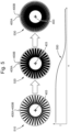
- Figure 5 is a schematic depiction of how a Moiré pattern can be generated according to the present invention.
- the offset between patterns is generated by rotation.
- Schematics 510, 520 and 530 illustrate the interference pattern generated by two superimposed copies of pattern 400, the two copies referred to as pattern 400A and pattern 400B.
- pattern 400B is rotated clockwise with respect to pattern 400A.
- the first component 401 of both patterns 400A and 400B is opaque, and the second component 402 of both patterns 400A and 400B is transparent.
- the term “Moiré pattern” refers to this interference pattern produced by superimposing pattern 400A and pattern 400B.
- the Moiré pattern resulting from pattern 400A and pattern 400B depends on the relative placement of the first component 401A of pattern 400A and the second component 402A of pattern 400A, with the first component 401B of pattern 400B and the second component 402B of pattern 400B.
- the resulting Moiré pattern can be inferred using binary logic.
- Pattern 400A can be considered as a first input, and pattern 400B can be considered as a second input.
- the first component 401 of both patterns 400A and 400B can be considered a [1] input, and the second component 402 of both patterns 400A and 400B can be considered a [0] input.
- the resulting Moiré pattern can therefore be considered an "400A OR 400B" operation in binary logic, applied across the whole 2-dimensional pattern.
- this component of the Moiré pattern has the appearance of a first component 401 (in the Figure, it is opaque/black).
- this component of the Moiré pattern also has the appearance of a first component 401 (in the Figure, it is opaque/black).
- this component of the Moiré pattern also has the appearance of a first component 401 (in the Figure, it is opaque/black).
- this component of the Moiré pattern also has the appearance of a first component 401 (in the Figure, it is opaque/black).
- this component of the Moiré pattern also has the appearance of a first component 401 (in the Figure, it is opaque/black).
- this component of the Moiré pattern has the appearance of a second component 402 (in the Figure, it is transparent/white).
- the two patterns 400A and 400B are superimposed on each other with an identical axis 403, and are aligned by a common axis of rotational symmetry.
- the resulting interference pattern has the appearance of either one of pattern 400A or 400B. In other words, no interference pattern is apparent.
- Schematic 530 shows a further clockwise rotation of pattern 400B with respect to pattern 400A.
- the two patterns are perfectly "out of phase” with respect to their axes of rotational symmetry.
- a first component 401 in the Figure, opaque/black
- the overall Moiré pattern is as "dark", or "opaque” as possible.
- the resulting Moiré patterns 510, 520 and 530 have different proportions of a first component 401 and a second component 402, wherein the first component in the Figure is black/opaque and the second component in the Figure is transparent/white.
- the present apparatus and method uses the phenomenon of these different Moiré patterns in order to measure a property difference between two targets, explained in detail below.
- curve 550 indicates how the proportion of a second component 402 on the Moiré pattern varies as the patterns 400A and 400B are rotated relative to each other.
- the vertical axis "I” denotes the total area of the second component 402 in the Moiré pattern.
- Axis “I” can also be considered to denote the amount of light that is able to pass through the Moiré pattern if the second component 402 is transparent.
- the horizontal axis " ⁇ ” denotes the angle of rotation of pattern 400B relative to pattern 400A.
- the curve 550 corresponds to the Moiré schematics 510, 520 and 530 above it.
- the first component 401 and the second component 402 are distinguished by any difference in an optical property, or other property. Therefore, the "value I" can generally be considered to be the transmissivity, of the Moiré pattern, where the second component 402 has a higher transmissivity than the first component 401.
- This variation in the value I can occur with respect to relative rotation, even when the whole area of the Moiré pattern is not observed.
- a variation in I may be observed when only a small portion of the total pattern area is observed. Accordingly in the foregoing, a variation in I may refer to this property over a whole pattern, or refer to this property over a smaller area of the pattern.
- Figure 6 depicts a portion of the Moiré pattern that is generated due to the relative rotation of patterns, similarly to as in Figure 5 .
- Pattern 400 is depicted with an area of observation 600.
- the area of observation 600 only encompasses the ends of several spokes in the pattern 400.
- Subfigures 610, 620 and 630 show the area of observation 600 for the schematics 510, 520 and 530. Subfigures 610, 620 and 630 show that while the whole pattern is not under observation, a change in the ratio between the first opaque/black component 401 and a second transparent/white component 402. Therefore in the foregoing it should be understood that the change in the ratio between the first opaque/black component 401 and a second transparent/white component 402, or the change in the value of I occurs not only over the whole Moiré pattern, but also occurs independently in small portions of the Moiré pattern.
- Schematics 530 and 630 portray the Moiré pattern arising when patterns 400A and 400B are completely out of phase. If pattern 400B was further rotated clockwise from its position in schematics 530 and 630, a Moiré pattern similar to 520 and 620 would arise. If pattern 400B was even further rotated clockwise, the points of rotational symmetry of 400A and 400B would at some point align again, as in 510 and 610.
- rotating pattern 400B with respect to pattern 400A at a constant angular velocity yields a periodic fluctuation in the value of I.
- the peaks in the value of I correspond to where the points of rotational symmetry of patterns 400A and 400B align.
- the troughs in the value of I correspond to where the axes of rotational symmetry of patterns 400A and 400B are completely out of phase.
- Figure 7 illustrates the periodic fluctuation in the value of I for two different relative angular speeds between the patterns 400A and 400B.
- the vertical axis denotes the value of I and the horizontal axis denotes time.
- the curves 710 and 720 denote the variation of the value of I over time.
- a first angular speed ⁇ 1 is lower than a second angular speed ⁇ 2.
- the curve 710 depicts the time-dependent variation of I when 400B rotates at the angular velocity ⁇ 1.
- the curve 720 depicts the time-dependent variation of I when 400B rotates at the angular velocity ⁇ 2.
- Curve 710 has a lower frequency than curve 720.
- the period T1 is larger than the period T2.
- pattern 400A is kept stationary, and pattern 400B is rotated relative to pattern 400A, the speed of angular rotation ⁇ of the pattern 400B can be inferred from the frequency of oscillation in the value of I.
- a higher frequency of oscillation in the value of I denotes a higher speed of angular rotation ⁇ .
- the Moiré patterns of the present invention are particularly suitable for taking a difference measurement.
- the speed of rotation of a first member containing a pattern that has an angular variation is based on a property of a first target; and the speed of rotation of a second member containing a pattern that has an angular variation is based on a property of a second target.
- the patterns on the first and second members are superimposed to generate a Moiré pattern.
- any change in the Moiré pattern depends on the magnitude of the difference between the property of the targets, and not the magnitude of the property of the targets. This gives rise to a higher accuracy. In essence, the "common mode signal" between the property of the first target and the property of the second target is eliminated.
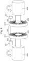
- Figure 8 depicts a practical example of the above principle applied to an apparatus for detecting leaks in a lithographic apparatus.
- a first flow rotor 802A is coupled to a first point in a channel of the fluid circulation system, e.g. at the inlet, and configured to rotate in accordance with the rate of flow at the first point.
- the first flow rotor 802A is configured to rotate at a rate that is proportional to the mass flow rate of fluid at the first point.
- a second flow rotor 802B is coupled to a second point in the channel of the fluid circulation system, e.g. at the outlet, and configured to rotate in accordance with the rate of flow at the second point.
- the second flow rotor 802B is configured to rotate at a rate that is proportional to the mass flow rate of fluid at the second point. Desirably the relationship between rate of rotation of each of rotors 802A, 802B and flow at the respective points in the channel is the same.
- the flow rotors do not have to be disposed at the inlet and outlet but can be disposed anywhere convenient in a fluid circulation system. Multiple pairs of flow rotors may be disposed within a fluid circulation system so as to allow the location of any leak to be determined.
- Each of flow rotors 802A, 802B is coupled to a respective one of first and second transparent disks 801A, 801B.
- Transparent disks 801A, 801B are examples of rotating members.
- First pattern 400A is provided on first transparent disk 801A and second pattern 400B is provided on second transparent disk 801B.
- a light source 803 e.g. a laser, LED or laser diode
- emits a first beam 810 toward transparent disk the light is modulated by the first pattern and propagates in a second beam 820 to the second transparent disk 801B.
- the light is further modulated by the second pattern 400B and propagates to a detector 804 as a third beam 830.
- the combination of the modulation of the light by the first and second patterns 400A, 400B represents or encodes the Moiré pattern defined by the relative angular positions of the first and second transparent disks 801A, 801B.
- Light source 803 may include focusing, collimating, directing or other beam forming components.
- Detector 804 may include light collecting elements and filters to reject stray light.
- an intensity signal measured by the detector 804 will vary with time.
- the time variation will comprise two signal components: a first signal component determined by the angular frequency of the first pattern 400A and the rate of rotation of second transparent disk 801A and a second signal component determined by the angular frequency of the second pattern 400B and the rate of rotation of second transparent disk 801B. Since it is expected that any leak in the fluid circulation system is small compared to the flow rate through the system, the difference in frequency between the first and second signal components will be small, the sum of these components will provide a signal that is the combination of a fundamental signal and a beat signal.
- the beat signal represents the Moiré pattern and can be detected by various means such as: a frequency analyzer, a low-pass filter or a fast Fourier transform (FFT).
- FFT fast Fourier transform
- Figure 8 depicts a very simple embodiment of the invention and many variations thereon are possible.
- gearing can be provided between the flow rotors and the transparent disks to increase the rate of rotation of the transparent disks.
- Such gearing increases the frequency of the fundamental signal and beat signal which can make them easier to separate and increase accuracy of measurement of the beat signal and hence the leak rate.
- optical system can be provided to conduct the beam as required.
- the optical system may comprise: optical fibers; free space optics such as lenses and mirrors; or any combination thereof.
- Optical fibers may be especially advantageous if the two points in the fluid circulation system are far apart.
- the light beam can be conducted through the two transparent disks multiple times. Such an arrangement may be advantageous in increasing the variation in the intensity signal if the patterns have low contrast.
- the relative sizes of the cross-section of the beam and the pattern components can be selected for various different effects. If the beam is small relative to the pattern components then the fundamental signal will have a large amplitude. This can be useful for noise rejection or to enable an absolute flow rate measurement to be obtained in addition to the differential flow rate. If the beam is large compared to the pattern components the amplitude of the fundamental signal will be reduced and can be made negligible. This can avoid the need to electronically separate the beat signal representing the Moiré pattern from the fundamental signal.
- the patterns 400A, 400B are each divided into two corresponding concentric annular regions.
- the angular frequency of the two components 401, 402 in a first annular region is different than the angular frequency of the two components in a second annular region.
- Desirably the angular frequencies of the two annular regions are mutually prime.
- the light beam is arranged to pass through both annular regions, e.g. by being large enough to overlap both annular regions.
- two light beams, one passing through each annular region can be used.
- the two light beams can be directed onto one sensor or have separate sensors whose outputs are combined electronically.
- This arrangement can address an issue that if the two transparent discs develop a constant offset whereby their patterns are exactly out of phase no light reaches the detector 804 which can make signal acquisition difficult and result in a low signal to noise ratio such that dark noise in the detector can lead to false positives. Since, in this arrangement the patterns in the two annular regions have different angular frequencies there will be no relative position of the two discs in which both annular regions are completely opaque.
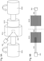
- the discs are replaced by drums 901A, 901B and the radial patterns are replaced by patterns 410A, 410B comprising dark bands 411 and light bands 412.
- Drums 901A, 901B are examples of rotating members.
- Other parts of this embodiment are the same as those of the embodiment of Figure 8 and have like reference numerals.
- Dark bands 411 and light bands 412 can be parallel to the axis of the respective drum or at an angle so as to form spirals. Like the regions 401, 402 the duty ratio of the dark and light bands is desirably 50% but other values are possible.
- drums 901A, 901B Various different configurations are possible with drums 901A, 901B.
- the light bands of both drums are transparent and drum 901B is located inside drum 901A, e.g. concentrically.
- Light source 803 is outside drum 901B and detector 804 is inside drum 901B so that light passes through both drums.
- the light bands of drum 901B are reflective and detector 804 is outside drum 901A, e.g. adjacent light source 803.
- drums 901A and 901B are spaced apart rather than nested and the light bands on both drums are reflective.
- the light source is arranged to direct light onto the drums so that it reflects off both to reach the detector.
- the drums need not be cylindrical, for example conical drums can be convenient in some configurations, nor do both drums need to have the same shape. Other configurations are possible.
- a "light region” or “light band” of a pattern is one which allows light to reach the detector whereas a “dark region” or “dark band” is one which prevents or reduces light reaching the detector.
- a light region might be transmissive or reflective.
- a dark region may be transmissive, reflective or absorbing.
- the flow rotors measure mass flow rate. It is also possible to use flow rotors that measure volume flow rate. In that case, if there is a significant temperature difference between the fluid at the first point and the fluid at the second point and the fluid has a non-negligible coefficient of thermal expansion, it is possible to measure the temperatures of the fluid at the two points and apply a correction to the apparent leakage measured by the flow differential.
- the present invention can be used to measure intentional differences between two flows. For example it might be useful to know the flow rate in a small branch off a main flow where it is difficult to measure the flow in the branch to be measured directly.
- the present invention can be used to measure the difference in flows in a main channel before and after a branch and thereby infer the flow in the branch.
- Embodiments of the invention have been described in the context of a lithographic apparatus employing EUV radiation. It will be appreciated that the invention may also be applied in other type of lithography apparatus - such as DUV lithographic apparatus, e-beam lithographic apparatus or imprint lithographic apparatus - and to other tools used in semiconductor manufacture such as assessment tools (e.g. metrology tools, inspection tools and scanning electron microscopes). Lithographic apparatus and these other tools may be collectively referred to as lithographic tools and have the common characteristics that fluids, e.g. water, are circulated through the tool, e.g. for temperature control, and that leaks of fluid may lead to very costly damage and downtime.
- fluids e.g. water
- lithographic apparatus in the manufacture of ICs
- the lithographic apparatus described herein may have other applications, such as the manufacture of integrated optical systems, guidance and detection patterns for magnetic domain memories, flat-panel displays, liquid-crystal displays (LCDs), thin film magnetic heads, etc.
- LCDs liquid-crystal displays
- any use of the terms “wafer” or “die” herein may be considered as synonymous with the more general terms “substrate” or "target portion”, respectively.
- the substrate referred to herein may be processed, before or after exposure, in for example a track (a tool that typically applies a layer of resist to a substrate and develops the exposed resist), a metrology tool and/or an inspection tool. Where applicable, the invention herein may be applied to such and other substrate processing tools. Further, the substrate may be processed more than once, for example in order to create a multi-layer IC, so that the term substrate used herein may also refer to a substrate that already contains one or multiple processed layers.
Landscapes
- Physics & Mathematics (AREA)
- General Physics & Mathematics (AREA)
- Health & Medical Sciences (AREA)
- Epidemiology (AREA)
- Public Health (AREA)
- Engineering & Computer Science (AREA)
- Environmental & Geological Engineering (AREA)
- Fluid Mechanics (AREA)
- Life Sciences & Earth Sciences (AREA)
- Atmospheric Sciences (AREA)
- Exposure And Positioning Against Photoresist Photosensitive Materials (AREA)
- Length Measuring Devices By Optical Means (AREA)
Claims (14)
- Un système pour mesurer la différence entre un débit d'une première cible et un débit d'une deuxième cible, le système comprenant un premier élément et un deuxième élément, où :le premier élément comprend un premier motif (400A) et est agencé afin de tourner à une première vitesse de rotation, où la première vitesse de rotation du premier élément est configurée afin d'être basée sur le débit de la première cible ; etle deuxième élément comprend un deuxième motif (400B) et est agencé afin de tourner à une deuxième vitesse de rotation, où la deuxième vitesse de rotation du deuxième élément est configurée afin d'être basée sur le débit de la deuxième cible,en sus où le premier et le deuxième motif présentent une variation angulaire et sont configurés afin de générer un motif d'interférence par leur interaction lorsque les premier et deuxième éléments présentent une différence relative de leurs vitesses de rotation, le motif d'interférence étant indicatif de la magnitude de cette différence.
- Le système de la revendication 1, où les premier et deuxième motifs comprennent un premier et un deuxième composant, où :a. le premier composant présente une transmissivité inférieure à celle du deuxième composant ; oub. le premier composant présente une réflectivité inférieure à celle du deuxième composant.
- Le système de n'importe lesquelles des revendications 1 ou 2, où le premier élément est attaché à un rotor à débit (802A) disposé au niveau d'une entrée, et le deuxième élément est attaché à un rotor à débit (802B) disposé au niveau d'une sortie ; facultativement où les premier et deuxième éléments sont attachés aux rotors à débit par le biais d'un mécanisme d'engrenage, de telle sorte que la vitesse de rotation des premier et deuxième éléments est plus élevée que la vitesse de rotation des rotors à débit respectifs.
- Le système de n'importe lesquelles des revendications 1 à 3, où les premier et deuxième éléments sont des disques (801A, 801B), les premier et deuxième motifs étant formés sur ou à travers une surface des disques.
- Le système de n'importe lesquelles des revendications 1 à 4, où les premier et deuxième éléments sont des tambours concentriques (901A, 901B), les premier et deuxième motifs étant formés sur ou à travers la surface des tambours dans une portion en chevauchement des tambours.
- Le système de n'importe lesquelles des revendications 1 à 5, où une source lumineuse (803) est disposée afin que de la lumière soit incidente sur ou à travers le motif d'interférence, et un capteur (804) est configuré afin de recevoir le signal lumineux indicatif de la différence relative de vitesses de rotation entre les premier et deuxième éléments, facultativement où une fibre optique est disposée entre les premier et deuxième éléments afin de communiquer de la lumière provenant de la source lumineuse entre eux.
- Le système de n'importe lesquelles des revendications 1 à 6, où un ou plusieurs capteurs de température sont configurés afin de mesurer une température au niveau des première et deuxième cibles, de telle sorte que la magnitude du signal de différence fourni par le motif d'interférence peut être calibrée sur la base de la différence de température mesurée.
- Le système de n'importe lesquelles des revendications 1 à 7, où le premier motif est différent du deuxième motif, de telle sorte que lorsque les premier et deuxième éléments tournent à la même vitesse, le motif superposé résultant entre le premier et le deuxième motif est un motif à variation angulaire.
- Le système de n'importe lesquelles des revendications 1 à 4, où le premier motif et le deuxième motif sont divisés en deux régions annulaires concentriques.
- Un outil lithographique présentant un système de circulation de fluide, le système de circulation de fluide présentant une entrée de fluide et une sortie de fluide, et un système selon n'importe laquelle des revendications précédentes configuré afin de mesurer une différence entre les débits dans l'entrée de fluide et la sortie de fluide.
- Un outil lithographique selon la revendication 10 où le système de circulation de fluide est configuré afin de faire circuler de l'eau contrôlée en température.
- Un procédé de mesure de la différence entre un débit d'une première cible et un débit d'une deuxième cible, le procédé comprenant le fait :d'entraîner en rotation un premier élément comprenant un premier motif (400A) à une première vitesse basée sur le débit de la première cible ;d'entraîner en rotation un deuxième élément comprenant un deuxième motif (400B) à une deuxième vitesse basée sur le débit de la deuxième cible ;moyennant quoi un motif d'interférence entre les premier et deuxième motifs est formé lorsque les premier et deuxième éléments présentent une différence relative de leur vitesse de rotation ; etde prendre une mesure différentielle du débit des première et deuxième cibles basée sur le motif d'interférence.
- Le procédé de la revendication 12, comprenant en sus le fait :de surveiller une première température relative à la première cible ;de surveiller une deuxième température relative à la deuxième cible ; etd'utiliser la différence entre la première température et la deuxième température afin de calibrer la mesure différentielle de débit inférée entre les première et deuxième cibles basée sur le motif d'interférence.
- Le procédé de n'importe lesquelles des revendications 12 ou 13, comprenant en sus le fait :de fournir un faisceau afin qu'il soit incident sur ou qu'il traverse dans sa course les premier et deuxième motifs de manière à être modulé par motif d'interférence ;de surveiller une amplitude du faisceau après qu'il a été modulé par le motif d'interférence ; etde déterminer une différence entre le débit des première et deuxième cibles basée sur l'amplitude du faisceau au fil du temps.
Applications Claiming Priority (2)
| Application Number | Priority Date | Filing Date | Title |
|---|---|---|---|
| EP20168356 | 2020-04-07 | ||
| PCT/EP2021/055884 WO2021204478A1 (fr) | 2020-04-07 | 2021-03-09 | Système de mesure différentielle |
Publications (2)
| Publication Number | Publication Date |
|---|---|
| EP4133335A1 EP4133335A1 (fr) | 2023-02-15 |
| EP4133335B1 true EP4133335B1 (fr) | 2025-06-18 |
Family
ID=70227788
Family Applications (1)
| Application Number | Title | Priority Date | Filing Date |
|---|---|---|---|
| EP21709440.8A Active EP4133335B1 (fr) | 2020-04-07 | 2021-03-09 | Système de mesure différentielle |
Country Status (5)
| Country | Link |
|---|---|
| US (1) | US12248255B2 (fr) |
| EP (1) | EP4133335B1 (fr) |
| JP (1) | JP7402350B2 (fr) |
| CN (1) | CN115335773A (fr) |
| WO (1) | WO2021204478A1 (fr) |
Citations (6)
| Publication number | Priority date | Publication date | Assignee | Title |
|---|---|---|---|---|
| US3688570A (en) * | 1970-06-05 | 1972-09-05 | Polaroid Corp | Angular deflection meter |
| US4286471A (en) * | 1979-06-04 | 1981-09-01 | Rockwell International Corporation | Constant accuracy turbine meter |
| JPH08271287A (ja) * | 1995-03-31 | 1996-10-18 | Canon Inc | 変位情報検出装置及びこれを用いたドライブ制御装置及びスケール装置 |
| GB2352811A (en) * | 1999-08-06 | 2001-02-07 | Mitutoyo Corp | Optical encoder |
| WO2017125254A1 (fr) * | 2016-01-18 | 2017-07-27 | Asml Netherlands B.V. | Système de mesure de faisceau, système lithographique, et procédé |
| US20180073387A1 (en) * | 2016-09-15 | 2018-03-15 | Rolls-Royce Deutschland Ltd & Co Kg | Device and method for measuring a rotational movement, in particular a rotational direction, and for detecting a shaft break |
Family Cites Families (14)
| Publication number | Priority date | Publication date | Assignee | Title |
|---|---|---|---|---|
| US4692614A (en) * | 1985-04-27 | 1987-09-08 | The Marconi Company Limited | Rotational motion fluid loop sensor using magnetically levitated detecting element |
| GB2185785B (en) * | 1986-01-25 | 1989-11-01 | Ford Motor Co | Liquid flow meter |
| JPS6472021A (en) | 1987-05-11 | 1989-03-16 | Honda Motor Co Ltd | Torque detecting device |
| DE19932965A1 (de) | 1999-07-14 | 2001-01-25 | Siemens Ag | Optischer Drehmomentsensor mit MoirE-Musterdetektion und Nullpunktabgleich |
| US6817528B2 (en) * | 2001-07-17 | 2004-11-16 | Honeywell International Inc. | Reflective apparatus and method for optically sensing relative torque employing Moirè fringes |
| US20030015591A1 (en) * | 2001-07-17 | 2003-01-23 | Chen Bo Su | Transmissive apparatus and method for optically sensing relative torque employing moire fringes |
| CN102043350B (zh) * | 2003-07-28 | 2014-01-29 | 株式会社尼康 | 曝光装置、器件制造方法、及曝光装置的控制方法 |
| JPWO2008053738A1 (ja) | 2006-10-30 | 2010-02-25 | 国立大学法人大阪大学 | モアレ現象を利用した光ゲーティングシステム |
| NL2004820A (en) | 2009-06-30 | 2011-01-04 | Asml Netherlands Bv | Lithographic apparatus and a method of measuring flow rate in a two phase flow. |
| NL2007182A (en) * | 2010-08-23 | 2012-02-27 | Asml Netherlands Bv | Fluid handling structure, module for an immersion lithographic apparatus, lithographic apparatus and device manufacturing method. |
| TWI638241B (zh) | 2012-03-26 | 2018-10-11 | 日商尼康股份有限公司 | 基板處理裝置、處理裝置及元件製造方法 |
| US9547241B2 (en) * | 2013-05-07 | 2017-01-17 | Asml Netherlands B.V. | Alignment sensor, lithographic apparatus and alignment method |
| WO2015177780A1 (fr) | 2014-05-19 | 2015-11-26 | Hamut - Mechanics And Technology Compny Ltd | Système de détection de fuites de fluide |
| CN109708823B (zh) | 2019-01-17 | 2020-08-14 | 同济大学 | 一种用于旋转密封结构测试的试验装置及测试方法 |
-
2021
- 2021-03-09 EP EP21709440.8A patent/EP4133335B1/fr active Active
- 2021-03-09 CN CN202180022761.5A patent/CN115335773A/zh active Pending
- 2021-03-09 US US17/916,730 patent/US12248255B2/en active Active
- 2021-03-09 JP JP2022554489A patent/JP7402350B2/ja active Active
- 2021-03-09 WO PCT/EP2021/055884 patent/WO2021204478A1/fr not_active Ceased
Patent Citations (6)
| Publication number | Priority date | Publication date | Assignee | Title |
|---|---|---|---|---|
| US3688570A (en) * | 1970-06-05 | 1972-09-05 | Polaroid Corp | Angular deflection meter |
| US4286471A (en) * | 1979-06-04 | 1981-09-01 | Rockwell International Corporation | Constant accuracy turbine meter |
| JPH08271287A (ja) * | 1995-03-31 | 1996-10-18 | Canon Inc | 変位情報検出装置及びこれを用いたドライブ制御装置及びスケール装置 |
| GB2352811A (en) * | 1999-08-06 | 2001-02-07 | Mitutoyo Corp | Optical encoder |
| WO2017125254A1 (fr) * | 2016-01-18 | 2017-07-27 | Asml Netherlands B.V. | Système de mesure de faisceau, système lithographique, et procédé |
| US20180073387A1 (en) * | 2016-09-15 | 2018-03-15 | Rolls-Royce Deutschland Ltd & Co Kg | Device and method for measuring a rotational movement, in particular a rotational direction, and for detecting a shaft break |
Also Published As
| Publication number | Publication date |
|---|---|
| US20230152718A1 (en) | 2023-05-18 |
| EP4133335A1 (fr) | 2023-02-15 |
| US12248255B2 (en) | 2025-03-11 |
| JP7402350B2 (ja) | 2023-12-20 |
| JP2023520629A (ja) | 2023-05-18 |
| WO2021204478A1 (fr) | 2021-10-14 |
| CN115335773A (zh) | 2022-11-11 |
Similar Documents
| Publication | Publication Date | Title |
|---|---|---|
| JP4909977B2 (ja) | アラインメントシステム、リソグラフィ投影装置、デバイス製造方法、アラインメント構造、およびアラインメント方法 | |
| US8120001B2 (en) | Inspection method and apparatus, lithographic apparatus, lithographic processing cell and device manufacturing method | |
| JP6246330B2 (ja) | アライメントセンサ、リソグラフィ装置およびアライメント方法 | |
| KR100886741B1 (ko) | 기판상의 또는 기판에 근접한 타겟 이미지의 위치를결정하는 방법, 측정 디바이스, 및 리소그래피 장치 | |
| JP2013518261A (ja) | 空間フィルタを有するホログラフィックマスク検査システム | |
| KR102125876B1 (ko) | 리소그래피 장치 및 방법 | |
| TWI485395B (zh) | 時間差光罩檢測 | |
| CN111051994B (zh) | 用于测量光刻装置的焦点性能的方法和图案化设备与装置、器件制造方法 | |
| US8958053B2 (en) | Lithographic apparatus and alignment method | |
| JP2023538850A (ja) | リソグラフィ装置、計測システム及び誤差補正のための強度不均衡測定 | |
| KR102665402B1 (ko) | 센서 장치, 및 리소그래피 측정 방법 | |
| EP4133335B1 (fr) | Système de mesure différentielle | |
| NL2025287A (en) | Differential measurement system | |
| TWI881865B (zh) | 光學系統 | |
| WO2021018676A1 (fr) | Capteur d'alignement basé sur un balayage en longueur d'onde | |
| JP2019530894A (ja) | アライメントシステムの断熱化 | |
| JP6564138B2 (ja) | アライメントシステムの光学システム | |
| JP2006210895A (ja) | 傾斜焦点試験を行う方法及び露光装置、並びにそれに応じて製造されたデバイス | |
| NL2006644A (en) | Lithographic apparatus and alignment method. |
Legal Events
| Date | Code | Title | Description |
|---|---|---|---|
| STAA | Information on the status of an ep patent application or granted ep patent |
Free format text: STATUS: UNKNOWN |
|
| STAA | Information on the status of an ep patent application or granted ep patent |
Free format text: STATUS: THE INTERNATIONAL PUBLICATION HAS BEEN MADE |
|
| PUAI | Public reference made under article 153(3) epc to a published international application that has entered the european phase |
Free format text: ORIGINAL CODE: 0009012 |
|
| STAA | Information on the status of an ep patent application or granted ep patent |
Free format text: STATUS: REQUEST FOR EXAMINATION WAS MADE |
|
| 17P | Request for examination filed |
Effective date: 20220907 |
|
| AK | Designated contracting states |
Kind code of ref document: A1 Designated state(s): AL AT BE BG CH CY CZ DE DK EE ES FI FR GB GR HR HU IE IS IT LI LT LU LV MC MK MT NL NO PL PT RO RS SE SI SK SM TR |
|
| P01 | Opt-out of the competence of the unified patent court (upc) registered |
Effective date: 20230414 |
|
| DAV | Request for validation of the european patent (deleted) | ||
| DAX | Request for extension of the european patent (deleted) | ||
| REG | Reference to a national code |
Ref country code: DE Ref legal event code: R079 Free format text: PREVIOUS MAIN CLASS: G03F0007200000 Ipc: G03F0007000000 Ref country code: DE Ref legal event code: R079 Ref document number: 602021032432 Country of ref document: DE Free format text: PREVIOUS MAIN CLASS: G03F0007200000 Ipc: G03F0007000000 |
|
| GRAP | Despatch of communication of intention to grant a patent |
Free format text: ORIGINAL CODE: EPIDOSNIGR1 |
|
| STAA | Information on the status of an ep patent application or granted ep patent |
Free format text: STATUS: GRANT OF PATENT IS INTENDED |
|
| GRAJ | Information related to disapproval of communication of intention to grant by the applicant or resumption of examination proceedings by the epo deleted |
Free format text: ORIGINAL CODE: EPIDOSDIGR1 |
|
| STAA | Information on the status of an ep patent application or granted ep patent |
Free format text: STATUS: REQUEST FOR EXAMINATION WAS MADE |
|
| GRAP | Despatch of communication of intention to grant a patent |
Free format text: ORIGINAL CODE: EPIDOSNIGR1 |
|
| STAA | Information on the status of an ep patent application or granted ep patent |
Free format text: STATUS: GRANT OF PATENT IS INTENDED |
|
| RIC1 | Information provided on ipc code assigned before grant |
Ipc: G01M 3/38 20060101ALI20250224BHEP Ipc: G01M 3/32 20060101ALI20250224BHEP Ipc: G01F 1/86 20060101ALI20250224BHEP Ipc: G01F 1/06 20060101ALI20250224BHEP Ipc: G03F 7/00 20060101AFI20250224BHEP |
|
| INTG | Intention to grant announced |
Effective date: 20250310 |
|
| INTC | Intention to grant announced (deleted) | ||
| INTG | Intention to grant announced |
Effective date: 20250328 |
|
| GRAS | Grant fee paid |
Free format text: ORIGINAL CODE: EPIDOSNIGR3 |
|
| GRAA | (expected) grant |
Free format text: ORIGINAL CODE: 0009210 |
|
| STAA | Information on the status of an ep patent application or granted ep patent |
Free format text: STATUS: THE PATENT HAS BEEN GRANTED |
|
| AK | Designated contracting states |
Kind code of ref document: B1 Designated state(s): AL AT BE BG CH CY CZ DE DK EE ES FI FR GB GR HR HU IE IS IT LI LT LU LV MC MK MT NL NO PL PT RO RS SE SI SK SM TR |
|
| REG | Reference to a national code |
Ref country code: GB Ref legal event code: FG4D |
|
| REG | Reference to a national code |
Ref country code: CH Ref legal event code: EP |
|
| REG | Reference to a national code |
Ref country code: DE Ref legal event code: R096 Ref document number: 602021032432 Country of ref document: DE |
|
| REG | Reference to a national code |
Ref country code: CH Ref legal event code: EP |
|
| REG | Reference to a national code |
Ref country code: IE Ref legal event code: FG4D |
|
| PG25 | Lapsed in a contracting state [announced via postgrant information from national office to epo] |
Ref country code: FI Free format text: LAPSE BECAUSE OF FAILURE TO SUBMIT A TRANSLATION OF THE DESCRIPTION OR TO PAY THE FEE WITHIN THE PRESCRIBED TIME-LIMIT Effective date: 20250618 |
|
| REG | Reference to a national code |
Ref country code: LT Ref legal event code: MG9D |
|
| PG25 | Lapsed in a contracting state [announced via postgrant information from national office to epo] |
Ref country code: NO Free format text: LAPSE BECAUSE OF FAILURE TO SUBMIT A TRANSLATION OF THE DESCRIPTION OR TO PAY THE FEE WITHIN THE PRESCRIBED TIME-LIMIT Effective date: 20250918 Ref country code: GR Free format text: LAPSE BECAUSE OF FAILURE TO SUBMIT A TRANSLATION OF THE DESCRIPTION OR TO PAY THE FEE WITHIN THE PRESCRIBED TIME-LIMIT Effective date: 20250919 |
|
| PG25 | Lapsed in a contracting state [announced via postgrant information from national office to epo] |
Ref country code: BG Free format text: LAPSE BECAUSE OF FAILURE TO SUBMIT A TRANSLATION OF THE DESCRIPTION OR TO PAY THE FEE WITHIN THE PRESCRIBED TIME-LIMIT Effective date: 20250618 |
|
| PG25 | Lapsed in a contracting state [announced via postgrant information from national office to epo] |
Ref country code: HR Free format text: LAPSE BECAUSE OF FAILURE TO SUBMIT A TRANSLATION OF THE DESCRIPTION OR TO PAY THE FEE WITHIN THE PRESCRIBED TIME-LIMIT Effective date: 20250618 |
|
| PG25 | Lapsed in a contracting state [announced via postgrant information from national office to epo] |
Ref country code: RS Free format text: LAPSE BECAUSE OF FAILURE TO SUBMIT A TRANSLATION OF THE DESCRIPTION OR TO PAY THE FEE WITHIN THE PRESCRIBED TIME-LIMIT Effective date: 20250918 |
|
| REG | Reference to a national code |
Ref country code: NL Ref legal event code: MP Effective date: 20250618 |
|
| PG25 | Lapsed in a contracting state [announced via postgrant information from national office to epo] |
Ref country code: LV Free format text: LAPSE BECAUSE OF FAILURE TO SUBMIT A TRANSLATION OF THE DESCRIPTION OR TO PAY THE FEE WITHIN THE PRESCRIBED TIME-LIMIT Effective date: 20250618 |
|
| PG25 | Lapsed in a contracting state [announced via postgrant information from national office to epo] |
Ref country code: NL Free format text: LAPSE BECAUSE OF FAILURE TO SUBMIT A TRANSLATION OF THE DESCRIPTION OR TO PAY THE FEE WITHIN THE PRESCRIBED TIME-LIMIT Effective date: 20250618 |
|
| PG25 | Lapsed in a contracting state [announced via postgrant information from national office to epo] |
Ref country code: PT Free format text: LAPSE BECAUSE OF FAILURE TO SUBMIT A TRANSLATION OF THE DESCRIPTION OR TO PAY THE FEE WITHIN THE PRESCRIBED TIME-LIMIT Effective date: 20251020 |
|
| REG | Reference to a national code |
Ref country code: AT Ref legal event code: MK05 Ref document number: 1804739 Country of ref document: AT Kind code of ref document: T Effective date: 20250618 |
|
| PG25 | Lapsed in a contracting state [announced via postgrant information from national office to epo] |
Ref country code: IS Free format text: LAPSE BECAUSE OF FAILURE TO SUBMIT A TRANSLATION OF THE DESCRIPTION OR TO PAY THE FEE WITHIN THE PRESCRIBED TIME-LIMIT Effective date: 20251018 |
|
| PG25 | Lapsed in a contracting state [announced via postgrant information from national office to epo] |
Ref country code: AT Free format text: LAPSE BECAUSE OF FAILURE TO SUBMIT A TRANSLATION OF THE DESCRIPTION OR TO PAY THE FEE WITHIN THE PRESCRIBED TIME-LIMIT Effective date: 20250618 Ref country code: SM Free format text: LAPSE BECAUSE OF FAILURE TO SUBMIT A TRANSLATION OF THE DESCRIPTION OR TO PAY THE FEE WITHIN THE PRESCRIBED TIME-LIMIT Effective date: 20250618 |
|
| PG25 | Lapsed in a contracting state [announced via postgrant information from national office to epo] |
Ref country code: CZ Free format text: LAPSE BECAUSE OF FAILURE TO SUBMIT A TRANSLATION OF THE DESCRIPTION OR TO PAY THE FEE WITHIN THE PRESCRIBED TIME-LIMIT Effective date: 20250618 |
|
| PG25 | Lapsed in a contracting state [announced via postgrant information from national office to epo] |
Ref country code: PL Free format text: LAPSE BECAUSE OF FAILURE TO SUBMIT A TRANSLATION OF THE DESCRIPTION OR TO PAY THE FEE WITHIN THE PRESCRIBED TIME-LIMIT Effective date: 20250618 |
|
| PG25 | Lapsed in a contracting state [announced via postgrant information from national office to epo] |
Ref country code: EE Free format text: LAPSE BECAUSE OF FAILURE TO SUBMIT A TRANSLATION OF THE DESCRIPTION OR TO PAY THE FEE WITHIN THE PRESCRIBED TIME-LIMIT Effective date: 20250618 |
|
| PG25 | Lapsed in a contracting state [announced via postgrant information from national office to epo] |
Ref country code: SK Free format text: LAPSE BECAUSE OF FAILURE TO SUBMIT A TRANSLATION OF THE DESCRIPTION OR TO PAY THE FEE WITHIN THE PRESCRIBED TIME-LIMIT Effective date: 20250618 |
|
| PG25 | Lapsed in a contracting state [announced via postgrant information from national office to epo] |
Ref country code: ES Free format text: LAPSE BECAUSE OF FAILURE TO SUBMIT A TRANSLATION OF THE DESCRIPTION OR TO PAY THE FEE WITHIN THE PRESCRIBED TIME-LIMIT Effective date: 20250618 |
|
| PG25 | Lapsed in a contracting state [announced via postgrant information from national office to epo] |
Ref country code: DK Free format text: LAPSE BECAUSE OF FAILURE TO SUBMIT A TRANSLATION OF THE DESCRIPTION OR TO PAY THE FEE WITHIN THE PRESCRIBED TIME-LIMIT Effective date: 20250618 |
|
| PG25 | Lapsed in a contracting state [announced via postgrant information from national office to epo] |
Ref country code: IT Free format text: LAPSE BECAUSE OF FAILURE TO SUBMIT A TRANSLATION OF THE DESCRIPTION OR TO PAY THE FEE WITHIN THE PRESCRIBED TIME-LIMIT Effective date: 20250618 |
|
| PLBE | No opposition filed within time limit |
Free format text: ORIGINAL CODE: 0009261 |
|
| STAA | Information on the status of an ep patent application or granted ep patent |
Free format text: STATUS: NO OPPOSITION FILED WITHIN TIME LIMIT |
|
| REG | Reference to a national code |
Ref country code: CH Ref legal event code: L10 Free format text: ST27 STATUS EVENT CODE: U-0-0-L10-L00 (AS PROVIDED BY THE NATIONAL OFFICE) Effective date: 20260430 |