EP4133565B1 - Dispositif filtrant - Google Patents
Dispositif filtrant Download PDFInfo
- Publication number
- EP4133565B1 EP4133565B1 EP21735233.5A EP21735233A EP4133565B1 EP 4133565 B1 EP4133565 B1 EP 4133565B1 EP 21735233 A EP21735233 A EP 21735233A EP 4133565 B1 EP4133565 B1 EP 4133565B1
- Authority
- EP
- European Patent Office
- Prior art keywords
- network
- unit
- capacitor
- converter
- voltage
- Prior art date
- Legal status (The legal status is an assumption and is not a legal conclusion. Google has not performed a legal analysis and makes no representation as to the accuracy of the status listed.)
- Active
Links
Images

Classifications
-
- H—ELECTRICITY
- H02—GENERATION; CONVERSION OR DISTRIBUTION OF ELECTRIC POWER
- H02J—ELECTRIC POWER NETWORKS; CIRCUIT ARRANGEMENTS OR SYSTEMS FOR SUPPLYING OR DISTRIBUTING ELECTRIC POWER; SYSTEMS FOR STORING ELECTRIC ENERGY
- H02J3/00—Circuit arrangements for AC mains or AC distribution networks
- H02J3/26—Arrangements for eliminating or reducing asymmetry in polyphase networks
-
- H—ELECTRICITY
- H02—GENERATION; CONVERSION OR DISTRIBUTION OF ELECTRIC POWER
- H02J—ELECTRIC POWER NETWORKS; CIRCUIT ARRANGEMENTS OR SYSTEMS FOR SUPPLYING OR DISTRIBUTING ELECTRIC POWER; SYSTEMS FOR STORING ELECTRIC ENERGY
- H02J3/00—Circuit arrangements for AC mains or AC distribution networks
- H02J3/001—Arrangements for handling faults or abnormalities, e.g. emergencies or contingencies
-
- H—ELECTRICITY
- H02—GENERATION; CONVERSION OR DISTRIBUTION OF ELECTRIC POWER
- H02M—APPARATUS FOR CONVERSION BETWEEN AC AND AC, BETWEEN AC AND DC, OR BETWEEN DC AND DC, AND FOR USE WITH MAINS OR SIMILAR POWER SUPPLY SYSTEMS; CONVERSION OF DC OR AC INPUT POWER INTO SURGE OUTPUT POWER; CONTROL OR REGULATION THEREOF
- H02M1/00—Details of apparatus for conversion
- H02M1/12—Arrangements for reducing harmonics from AC input or output
- H02M1/126—Arrangements for reducing harmonics from AC input or output using passive filters
-
- H—ELECTRICITY
- H02—GENERATION; CONVERSION OR DISTRIBUTION OF ELECTRIC POWER
- H02M—APPARATUS FOR CONVERSION BETWEEN AC AND AC, BETWEEN AC AND DC, OR BETWEEN DC AND DC, AND FOR USE WITH MAINS OR SIMILAR POWER SUPPLY SYSTEMS; CONVERSION OF DC OR AC INPUT POWER INTO SURGE OUTPUT POWER; CONTROL OR REGULATION THEREOF
- H02M1/00—Details of apparatus for conversion
- H02M1/12—Arrangements for reducing harmonics from AC input or output
- H02M1/123—Suppression of common mode voltage or current
-
- H—ELECTRICITY
- H02—GENERATION; CONVERSION OR DISTRIBUTION OF ELECTRIC POWER
- H02M—APPARATUS FOR CONVERSION BETWEEN AC AND AC, BETWEEN AC AND DC, OR BETWEEN DC AND DC, AND FOR USE WITH MAINS OR SIMILAR POWER SUPPLY SYSTEMS; CONVERSION OF DC OR AC INPUT POWER INTO SURGE OUTPUT POWER; CONTROL OR REGULATION THEREOF
- H02M5/00—Conversion of AC power input into AC power output, e.g. for change of voltage, for change of frequency, for change of number of phases
- H02M5/40—Conversion of AC power input into AC power output, e.g. for change of voltage, for change of frequency, for change of number of phases with intermediate conversion into DC
- H02M5/42—Conversion of AC power input into AC power output, e.g. for change of voltage, for change of frequency, for change of number of phases with intermediate conversion into DC by static converters
- H02M5/44—Conversion of AC power input into AC power output, e.g. for change of voltage, for change of frequency, for change of number of phases with intermediate conversion into DC by static converters using discharge tubes or semiconductor devices to convert the intermediate DC into AC
- H02M5/453—Conversion of AC power input into AC power output, e.g. for change of voltage, for change of frequency, for change of number of phases with intermediate conversion into DC by static converters using discharge tubes or semiconductor devices to convert the intermediate DC into AC using devices of a triode or transistor type requiring continuous application of a control signal
- H02M5/458—Conversion of AC power input into AC power output, e.g. for change of voltage, for change of frequency, for change of number of phases with intermediate conversion into DC by static converters using discharge tubes or semiconductor devices to convert the intermediate DC into AC using devices of a triode or transistor type requiring continuous application of a control signal using semiconductor devices only
-
- Y—GENERAL TAGGING OF NEW TECHNOLOGICAL DEVELOPMENTS; GENERAL TAGGING OF CROSS-SECTIONAL TECHNOLOGIES SPANNING OVER SEVERAL SECTIONS OF THE IPC; TECHNICAL SUBJECTS COVERED BY FORMER USPC CROSS-REFERENCE ART COLLECTIONS [XRACs] AND DIGESTS
- Y02—TECHNOLOGIES OR APPLICATIONS FOR MITIGATION OR ADAPTATION AGAINST CLIMATE CHANGE
- Y02E—REDUCTION OF GREENHOUSE GAS [GHG] EMISSIONS, RELATED TO ENERGY GENERATION, TRANSMISSION OR DISTRIBUTION
- Y02E40/00—Technologies for an efficient electrical power generation, transmission or distribution
- Y02E40/50—Arrangements for eliminating or reducing asymmetry in polyphase networks
Definitions
- the invention relates to a filter device for use in a converter on an alternating voltage network, comprising a choke unit and a capacitor unit.
- common-mode currents Currents in the individual phases of an electrical line are referred to as common-mode currents, which, in contrast to differential-mode currents, each have the same sign with regard to their current direction.
- the push-pull currents add up to zero in terms of their current direction, especially in the fault-free case, in the sum of their currents, i.e. that the total amount of current flowing to a consumer in the phases of an electrical line is equal to the amount of current flowing back from the consumer in the phases. This is particularly true when using a neutral conductor.
- the resulting disturbances are also called symmetrical disturbances or push-pull disturbances.
- Disturbances resulting from the common mode currents are also referred to as asymmetrical disturbances or common mode disturbances.
- Common mode interference is caused, for example, by spark interference in brushed motors, switching power supplies, and frequency converters for electrical machines, with significant electrical losses or loads in electrical devices, in the electrical lines connected to them and ultimately in the energy distribution system (grids, transformers) and energy producers (generators). may occur.
- common-mode filter For a common-mode filter, current-compensated chokes with a choke core are often used as a common-mode choke, with, for example, the turns wound around the common choke core per phase having the same number of turns.
- the common mode filter as a capacitor unit has so-called capacitors connected in a Y configuration (Y capacitor unit), which are connected to a ground potential by means of a protective conductor (PE).
- Y capacitor unit Y capacitor unit
- PE protective conductor
- This common mode filter with a usually very low-resistance connection of the Y capacitor unit via the protective conductor to the ground potential is particularly suitable for deriving the common mode current (the disturbance variable) when operating electrical devices, e.g. converters, on a TT network (TT French: Terre Terre) or TN network (TN French: Terre Neutre) with a network star point grounded to earth potential on the generator side of the network.
- TT network TT French: Terre Terre
- TN network TN French: Terre Neutre
- These networks have at least one of the following designs or connections of the network star point grounded to earth potential, according to which the protective conductor of the electrical line alone, the protective conductor by means of an at least partial combination of neutral conductor (N) and protective conductor or the The neutral conductor of the electrical line is connected solely to the grounded network star point on the generator side of the corresponding network (the power source).
- the Y capacitor unit of a common mode filter with a common mode choke for electrical devices cannot be operated on an IT network (French IT: Isoli Terre) that is monitored in particular for electrical interference, which is... of its phases, especially on the generator side (the power source), are designed to be ungrounded, i.e. isolated from the ground potential.
- IT network French IT: Isoli Terre
- no or only very low leakage currents are permitted, particularly via the Y capacitor unit and the protective conductor to earth potential.
- a TT network or a TN network in which, in contrast to a grounded network star point, there is an external conductor, i.e. a phase of the TT or TN network, on the generator side (the power source ) is connected to the grounded earth potential, no or only very low leakage currents to the earth potential may be permissible here for specific operating states, in particular via the Y capacitor unit and the protective conductor.
- the separation of the Y-capacitor unit from the grounded protective conductor leads, on the one hand, to the prevention or at least to the reduction of the leakage currents or also to a reduction in the voltage load on the capacitors of the Y-capacitor unit, but on the other hand, the current-compensated choke can be periodically driven into saturation, since the Dissipation path for the common mode currents of the common mode interference is ineffective at this point due to the separation of the Y capacitor unit. This can lead to excessive heating of the choke core of the current compensated choke and cause destruction of the common mode choke.
- the EP 2 048 771 A1 discloses a filter device for a drive connected between a rectifier module of a frequency converter and an AC power supply network.
- the filter device comprises an EMC filter with a common mode inductance, which has windings in each phase of the supply network, the windings being magnetically coupled to one another. Saturation of the common mode inductance of the EMC filter should be avoided in the sampling frequency range of the drive and in the resonance frequency range of the EMC filter.
- a circuit arrangement for a frequency converter which consists of a passive, network-side EMC filter and an active filter.
- the passive, network-side EMC filter has a capacitor arrangement of three with the respective phases of the network connected capacitors, which form a star point.
- the star point can be electrically connected to a ground potential via another capacitor using a switch.
- the invention is therefore based on the object of proposing an efficient filter device with a common mode choke and a capacitor unit, which is suitable, on the one hand, for use in a network with a grounded network star point and, on the other hand, for use in a network with a grounded outer conductor or a ground-free network, without the Common mode choke to heat up unacceptably.
- the object is achieved by a filter device with the features specified in claim 1, by a converter with the filter device according to the features specified in claim 8 and by a method for operating the filter device according to the features specified in claim 10.
- a filter device for use in a converter on an alternating voltage network, comprising a throttle unit, a capacitor unit and means for reducing the saturation of the throttle unit.
- the means for reducing the saturation of the throttle unit advantageously prevents the common mode choke from being heated to an inadmissible extent.
- the filter device with the choke unit can therefore be used as a common mode choke together with the capacitor unit for use, for example, of the converter in networks with different grounding concepts.
- Advantageous embodiments of the filter device are specified in the dependent claims.
- the filter device is grounded for a first operation of the converter on a network designed as an alternating voltage network External conductor or on a ground-free network designed as an AC voltage network, the means for reducing saturation being activated and the capacitor unit being separable from a grounded protective conductor.
- the AC voltage network as a network with a grounded outer conductor is advantageously understood to mean, in particular, TT networks or TN networks in which only one of the external conductors on the generator side of the respective network is connected to the earth potential and the ground-free network designed as an AC voltage network is more advantageous
- an IT network is understood in which the electrical phases are electrically insulated from the ground potential, particularly on the generator side of the network.
- an isolation transformer can advantageously be dispensed with.
- the means for reducing saturation in order to be able to prevent the inadmissible heating of the throttle unit, which can be operated as a common mode choke, for as many of its electrical states in the first operation as a result of the saturation reduction.
- the capacitor unit can be separated from the grounded protective conductor in this first operation, which preferably supports the prevention of unacceptable heating of the common mode choke.
- the filter device is prepared for a second operation of the converter on a network designed as an alternating voltage network with a grounded network star point, the capacitor unit being connectable to the grounded protective conductor for dissipating a current and the means for reducing saturation being deactivated.
- the alternating voltage network as a network with a grounded network star point is advantageously understood to mean, in particular, TT networks or TN networks, in which the network star point formed on the generator side of the respective network is connected to the earth potential.
- the capacitor unit In this second operation, it is therefore advantageous to be able to connect the capacitor unit to the grounded protective conductor in order to be able to derive the current that can be generated as a common mode current.
- the means for reducing saturation can preferably be deactivated in the second operation, which can efficiently support the current dissipation of the common mode current.
- the throttle unit comprises a first coil in a first AC voltage phase, a second coil in a second AC voltage phase and a third coil in a third AC voltage phase of the first AC voltage line, the means for reducing saturation has a fourth coil of the throttle unit, the throttle unit forms a common throttle core the first, second, third and fourth coils and the means for reducing saturation has a first contact unit for opening and closing a first electrical connection of a circuit on the fourth coil.
- the inadmissible heating of the common throttle core can advantageously be prevented via the fourth coil on the common throttle core of the throttle unit, which can be operated as a common mode choke, in particular as a current-compensated choke, and via the circuit on the fourth coil which is short-circuited by the first contact unit.
- the common mode current that can be generated as a current in the first operation can be neutralized at the common mode choke in such a way that the common choke core of the common mode choke is not driven into saturation in an impermissible manner, for example periodically.
- the current dissipation of the common mode current via the capacitor unit to the grounded A protective conductor is not necessary to prevent saturation of the common throttle core.
- This is advantageously suitable for using the filter device on the network designed as an AC voltage network with a grounded outer conductor or on the ground-free network designed as an AC voltage network.
- the capacitor unit comprises a first, second and third capacitor, the first capacitor is on the one hand with a first AC voltage phase of the first AC voltage line, the second capacitor on the one hand with a second AC voltage phase of the first AC voltage line and the third capacitor on the one hand with a third AC voltage phase of the first AC voltage line is electrically connected and, on the other hand, the capacitors form a capacitor star point.
- a second contact unit is designed for opening and closing a second electrical connection of the capacitor unit with the grounded protective conductor and the capacitors of the capacitor unit can be electrically connected to the grounded protective conductor via the capacitor star point and the second contact unit.
- the common mode current that can be generated as current in the second operation can advantageously be derived from the capacitor unit via the second contact unit to the grounded protective conductor.
- At least one of the contact units has an electromechanical connector or a semiconductor switch.
- the electromechanical connector can, for example, advantageously be designed as a screw connection but also as an electrical switch.
- At least one of the contact units is designed as a controllable switch.
- a controllable switch can be designed, for example, as an IGBT or MOSFET but also as a relay or contactor.
- At least one of the contact units can be controlled by means of a control signal from a control unit.
- the control unit can be comprised by the filter device but also, for example, by a control unit of the converter.
- It can also be designed as a control unit, which is comprised, for example, by a higher-level drive, automation or energy control. Should the network topology change, the filter device can be switched over in an efficient and advantageous manner, so that the filter device can be used for the first operation or the second operation of the converter.
- the contact units are designed as an electrical changer.
- the electrical changer also known as a changeover switch
- the first and second contact units are switched simultaneously and thus the contact units are switched simultaneously. For example, in a first switching state of the changer, the first contact unit is closed and the second contact unit is open. After activating the changer, it is then in a second switching state of the changer, the first contact unit is opened and the second contact unit is closed.
- This switching process of simultaneously switching the two contact units by the electrical changer can be carried out reversibly.
- the filter device is integrated into a converter housing of the converter.
- the integration of the filter device into the converter housing of the converter has the advantage, for example, that the converter in a compact design always has the filter device for connection to the different network topologies for the first and second operation of the converter and a customer can use the setting on the converter for the can decide for each company.
- a method for operating the filter device according to the invention is also proposed, wherein the filter device for the first operation of the converter is set on the network designed as an AC voltage network with a grounded outer conductor or on the ground-free network designed as an AC voltage network, or the filter device for the second Operation of the converter on the network designed as an AC voltage network with a grounded network star point is set.
- the means for reducing the saturation of the throttle unit is activated and the capacitor unit is separated from the grounded protective conductor.
- the capacitor unit in the second operation of the converter, is connected to the grounded protective conductor for current dissipation and the means for reducing saturation is deactivated.
- FIG 1 shows a schematic representation of a known filter device 101, which is electrically arranged on a first AC voltage line 113 and is electrically connected via the first AC voltage line 113 to a rectifier 134 of a converter 124.
- the converter 124 also has an inverter 135, which is electrically coupled to the rectifier 134 by means of a DC intermediate circuit 136.
- the converter 124 is coupled on the output side via the inverter 135 and a second AC voltage line 126 to an electrical machine 133, the electrical Machine 133 is connected to ground potential via a grounded protective conductor 119.
- the second AC voltage line 126 has a line shield 143, which is connected to the grounded protective conductor 119 and thus to the ground potential.
- line capacitances 144 are formed starting from the individual phases of the second AC voltage line 126 relative to the line shield 134.
- the filter device 101 has a choke unit 106 in the form of a common mode choke (current compensated choke) and a capacitor unit 103 on the first AC voltage line 113.
- the throttle unit 102 includes a first coil 106 in a first AC voltage phase 110, a second coil 107 in a second AC voltage phase 111 and a third coil 108 in a third AC voltage phase 112 of the first AC voltage line 113. Furthermore, the throttle unit 102 forms a common throttle core 129 on the first , second and third coils 106,107,108.
- the capacitor unit 103 includes first, second and third capacitors 115,116,117.
- the first capacitor 115 is, on the one hand, connected to the first AC voltage phase 110 of the first AC voltage line 113
- the second capacitor 116 is, on the one hand, connected to the second AC voltage phase 111 of the first AC voltage line 113
- the third capacitor 117 is, on the one hand, connected to the third AC voltage phase 112 of the first AC voltage line 113 and the Capacitors 115,116,117, on the other hand, form a capacitor star point 118.
- the capacitors 115,116,117 of the capacitor unit 103 are connected to the grounded protective conductor 119 via the capacitor star point 118. So a stream 132 can be in the form of a Common mode current is derived relative to the ground potential.
- a further capacitor can be connected in the connection between the capacitor star point 118 and the grounded protective conductor 119 (in FIG 1 Not shown) .
- the converter 124 with the filter device 101 is connected on the input side to an AC voltage network 127 by means of the first AC voltage line 113.
- the AC voltage network 127 is designed as a network with the grounded star point 128, here as a TN network with a grounded star point 128.
- the ground potential for the grounded star point 128 is connected to the protective conductor 119.
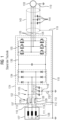
- FIG 2 shows in a first schematic representation the filter device 1 according to the invention, which is electrically arranged on a first AC voltage line 13 and is connected to a rectifier 34 of a converter 24 via the first AC voltage line 13.
- the converter 24 also has an inverter 35, which is electrically coupled to the rectifier 34 by means of a DC intermediate circuit 36.
- the converter 24 is coupled on the output side to an electrical machine 33 via the inverter 35 and a second AC voltage line 26, the electrical machine 33 being connected to earth potential via a grounded protective conductor 19.
- the second AC voltage line 26 has a line shield 43, which is connected to the grounded protective conductor 19 and thus to the ground potential.
- line capacitances 44 are formed starting from the individual phases of the second AC voltage line 26 relative to the line shield 34.
- the filter device 1 has a choke unit 6 in the form of a common mode choke (current-compensated choke) and a capacitor unit 3 on the first AC voltage line 3.
- a choke unit 6 in the form of a common mode choke (current-compensated choke) and a capacitor unit 3 on the first AC voltage line 3.
- the throttle unit 2 comprises a first coil 6 in a first AC voltage phase 10, a second coil 7 in a second AC voltage phase 11 and a third coil 8 in a third AC voltage phase 12 of the first AC voltage line 13.
- a means for reducing the saturation of the throttle unit 2 has a fourth coil 9 of the throttle unit 2.
- the means for reducing saturation further comprises a first contact unit 4 for opening and closing a first electrical connection of a circuit 14 on the fourth coil 9.
- the throttle unit 2 forms a common throttle core 29 on the first, second, third and fourth coils 6, 7, 8 .9 out.
- the circuit 14 on the fourth coil is in FIG 2 represented as short-circuited by the first contact unit 4, the means for reducing saturation being activated.
- the capacitor unit 3 includes a first, second and third capacitor 15, 16, 17.
- the first capacitor 15 is on the one hand with the first AC voltage phase 10 of the first AC voltage line 13
- the second capacitor 16 is on the one hand with the second AC voltage phase 11 of the first AC voltage line 13
- the third capacitor 17 is on the one hand with the third AC voltage phase 12 of the first AC voltage line 13 is connected and the capacitors 15, 16, 17 on the other hand form a capacitor star point 18.
- a current 32 in the form of a common mode current for a second operation of the converter 24 is in FIG 2 not derived from the earth potential.
- the two contact units 4.5 each with a controllable switch 22 per contact unit 4.5, can each be controlled alone or together by a control signal 20 from a control unit 21.
- Both contact units 4.5 are designed as an electrical changer 8.
- the converter 24 with the filter device 1 is connected on the input side to an AC voltage network 27 by means of the first AC voltage line 13.
- the AC voltage network 27 is designed as a network with a grounded outer conductor 25, here as a TT network with a grounded outer conductor 25.
- the ground potential for the grounded outer conductor 25 is not connected to the protective conductor 19.
- FIG 2 shown schematic representation of the filter device 1 for a first operation of the converter 24 on the network designed as an AC voltage network 27 with a grounded outer conductor 25.
- the converter 24 with the filter device 1 in this connection can also be connected to an AC voltage network 27 trained ground-free network, for example an IT network.
- the AC voltage network 27 is isolated from ground potential (in FIG 2 not shown) .
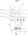
- FIG 3 is a second schematic representation of the filter device 1 according to the invention as a section FIG 2 shown.
- the filter device 1 is electrically arranged on the first alternating voltage line 13.
- the filter device 1 has the choke unit 6 in the form of a common mode choke (current-compensated choke) and the capacitor unit 3 on the first AC voltage line 3.
- the choke unit 6 in the form of a common mode choke (current-compensated choke) and the capacitor unit 3 on the first AC voltage line 3.
- the throttle unit 2 includes the first coil 6 in the first AC voltage phase 10, the second coil 7 in the second AC voltage phase 11 and the third coil 8 in the third AC voltage phase 12 of the first AC voltage line 13.
- the means for reducing the saturation of the throttle unit 2 has the fourth coil 9 of the throttle unit 2.
- the means for reducing saturation further comprises the first contact unit 4 for opening and closing the first electrical connection of the circuit 14 on the fourth coil 9.
- the throttle unit 2 forms the common throttle core 29 on the first, second, third and fourth coils 6, 7, 8 .9 out.
- the circuit 14 on the fourth coil is in FIG 3 represented as short-circuited by the first contact unit 4, the means for reducing saturation being activated.
- the capacitor unit 3 includes the first, second and third capacitors 15, 16, 17.
- the first capacitor 15 is on the one hand with the first AC voltage phase 10 of the first AC voltage line 13
- the second capacitor 16 is, on the one hand, connected to the second AC voltage phase 11 of the first AC voltage line 13
- the third capacitor 17 is, on the one hand, connected to the third AC voltage phase 12 of the first AC voltage line 13 and, on the other hand, the capacitors 15, 16, 17 form the capacitor star point 18.
- a current 32 in the form of a common mode current for the second operation of the converter is in FIG 3 not derived from the earth potential.
- the two contact units 4.5 are in FIG 3 each designed as an electromechanical connector 23 in the form of screw connections 22.
- the screw connection 22 of the second contact unit 5 is shown in dashed lines, which is intended to show the electromechanical connector 23 as open.
- FIG 3 excerpts FIG 2 shown schematic representation of the filter device 1 suitable for a first operation of the converter on the network designed as an AC voltage network with a grounded outer conductor (in FIG 3 Not shown).
- the converter with the filter device 1 in this circuit can also be operated on a ground-free network designed as an AC voltage network, for example an IT network.
- the alternating voltage network is isolated from earth potential (in FIG 3 not shown).
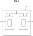
- FIG 4 a schematic structure diagram of a method 38 for the filter device according to the invention is visualized.
- the method 38 shows the operation of the filter device, after which the filter device for the first operation 39 of the converter is set for the network designed as an AC voltage network with a grounded outer conductor or for the ground-free network designed as an AC voltage network or the filter device for the second operation 40 of the converter for that A network designed as an alternating voltage network with a grounded network star point is set.
- the user of the filter device on the converter should decide on one of the two operating modes of the converter, first operation 39 or second operation 40.
- the means for reducing saturation 41 of the throttle unit is activated and the capacitor unit is separated from the grounded protective conductor, with the current derivation 41 being deactivated.
- the capacitor unit is connected to the grounded protective conductor, with the current derivation 42 activated and the means for reducing saturation 41 deactivated.
Landscapes
- Engineering & Computer Science (AREA)
- Power Engineering (AREA)
- Power Conversion In General (AREA)
Claims (12)
- Dispositif (1) de filtrage à utiliser pour un convertisseur (24) sur un réseau (27) de tension alternative, comportant une unité (2) de bobine, une unité (3) de condensateur et un moyen pour diminuer (41) la saturation de l'unité (2) de bobine, agencé pour un premier fonctionnement (39) du convertisseur (24) sur un réseau constitué en réseau (27) de tension alternative à conducteur (25) d'extérieur à la terre ou sur un réseau sans mise à la terre constitué sous la forme d'un réseau (27) de tension alternative, dans lequel le moyen de diminution (41) de la saturation peut être activé et l'unité (3) de condensateur peut être séparé d'un conducteur (19) de protection mis à la terre etagencé pour un deuxième fonctionnement (40) du convertisseur (24) sur un réseau constitué sous la forme d'un réseau (27) de tension alternative à point (28) neutre de réseau mis à la terre, dans lequel l'unité (3) de condensateur à conducteur (19) de protection mis à la terre peut être connectée pour la dérivation (42) d'un courant (32) et le moyen de diminution (41) de la saturation peut être désactivé,dans lequel- l'unité (2) de bobine comprend une première bobine (6) dans une première phase (10) de tension alternative, une deuxième bobine (7) dans une deuxième phase (11) de tension alternative et une troisième bobine (8) dans une troisième phase (12) de tension alternative de la première ligne (13) de tension alternative,- le moyen de diminution (41) de la saturation a une quatrième bobine (9) de l'unité (2) de bobine,- l'unité (2) de bobine constitue un noyau (29) commun de bobine sur la première, deuxième, troisième et quatrième bobine (6, 7, 8, 9) et- le moyen de diminution (41) de la saturation comprend une première unité (4) de contact pour l'ouverture et la fermeture d'une première liaison électrique d'un circuit (14) sur la quatrième bobine (9).
- Dispositif (1) de filtrage suivant la revendication 1, dans lequel- l'unité (3) de condensateur comprend un premier, deuxième et troisième condensateur (15, 16, 17)- le premier condensateur (15) est connecté d'une part à une première phase (10) de tension alternative de la première ligne (13) de tension alternative, le deuxième condensateur (16) d'une part à une deuxième phase (11) de tension alternative de la première ligne (13) de tension alternative et le troisième condensateur (17) d'une part à une troisième phase (12) de tension alternative de la première ligne (13) de tension alternative et- les condensateurs (15, 16, 17) constituent d'autre part un point (18) neutre de condensateur.
- Dispositif (1) de filtrage suivant la revendication 2, dans lequel une deuxième unité (5) de contact est constituée pour l'ouverture et la fermeture d'une deuxième liaison électrique de l'unité (3) de condensateur au conducteur (19) de protection mis à la terre et dans lequel les condensateurs (15, 16, 17) de l'unité (3) de condensateur peuvent être reliés électriquement par le point (18) neutre de condensateur et la deuxième unité (5) de contact au conducteur (19) de protection mis à la terre.
- Dispositif (1) de filtrage suivant l'une des revendications précédentes, dans lequel au moins l'une des unités (4, 5) de contact a un connecteur (23) électromécanique ou un interrupteur à semi-conducteur.
- Dispositif (1) de filtrage suivant l'une des revendications précédentes, dans lequel au moins l'une des unités (4, 5) de contact est constituée sous la forme d'un interrupteur (22) pouvant être commandé.
- Dispositif (1) de filtrage suivant la revendication 5, dans lequel au moins l'une des unités (4, 5) de contact peut être commandée au moyen d'un signal (20) de commande d'une unité (21) de commande.
- Dispositif (1) de filtrage suivant l'une des revendications précédentes, dans lequel les unités (4, 5) de contact sont constituées sous la forme d'un inverseur (31) électrique.
- Convertisseur (32) ayant un dispositif (1) de filtrage suivant l'une des revendications 1 à 7, pour faire fonctionner une machine (33) électrique sur un réseau (27) de tension alternative.
- Convertisseur (32) suivant la revendication 8, dans lequel le dispositif (1) de filtrage est intégré dans un boîtier (37) du convertisseur (32).
- Procédé (38) pour faire fonctionner un dispositif (1) de filtrage suivant l'une des revendications 1 à 7, dans lequel le dispositif (1) de filtrage est réglé pour le premier fonctionnement (39) de convertisseur (24) sur un réseau constitué en réseau (27) de tension alternative à conducteur (25) extérieur mis à la terre ou sur un réseau sans mis à la terre constitué en réseau (27) de tension alternative ou le dispositif (1) de filtrage est réglé pour le deuxième fonctionnement (40) du convertisseur (24) sur le réseau constitué en réseau (27) de tension alternative à point (28) neutre de réseau mis à la terre.
- Procédé (38) suivant la revendication 10, dans lequel dans le premier fonctionnement (39) du convertisseur (24) le moyen de diminution (41) de la saturation de l'unité (2) de bobine est activé et l'unité (3) de condensateur est séparé du conducteur (19) de protection mis à la terre.
- Procédé (38) suivant la revendication 10, dans lequel dans le deuxième fonctionnement (40) du convertisseur (24) l'unité (3) de condensateur est reliée au conducteur (19) de protection mis à la terre pour la dérivation (42) du courant et le moyen de diminution (41) de la saturation est désactivé.
Applications Claiming Priority (2)
| Application Number | Priority Date | Filing Date | Title |
|---|---|---|---|
| EP20182913.2A EP3934049A1 (fr) | 2020-06-29 | 2020-06-29 | Dispositif filtrant |
| PCT/EP2021/066608 WO2022002640A1 (fr) | 2020-06-29 | 2021-06-18 | Dispositif filtrant |
Publications (3)
| Publication Number | Publication Date |
|---|---|
| EP4133565A1 EP4133565A1 (fr) | 2023-02-15 |
| EP4133565B1 true EP4133565B1 (fr) | 2024-02-28 |
| EP4133565C0 EP4133565C0 (fr) | 2024-02-28 |
Family
ID=71401614
Family Applications (2)
| Application Number | Title | Priority Date | Filing Date |
|---|---|---|---|
| EP20182913.2A Withdrawn EP3934049A1 (fr) | 2020-06-29 | 2020-06-29 | Dispositif filtrant |
| EP21735233.5A Active EP4133565B1 (fr) | 2020-06-29 | 2021-06-18 | Dispositif filtrant |
Family Applications Before (1)
| Application Number | Title | Priority Date | Filing Date |
|---|---|---|---|
| EP20182913.2A Withdrawn EP3934049A1 (fr) | 2020-06-29 | 2020-06-29 | Dispositif filtrant |
Country Status (4)
| Country | Link |
|---|---|
| US (1) | US12316119B2 (fr) |
| EP (2) | EP3934049A1 (fr) |
| CN (1) | CN115735309A (fr) |
| WO (1) | WO2022002640A1 (fr) |
Family Cites Families (8)
| Publication number | Priority date | Publication date | Assignee | Title |
|---|---|---|---|---|
| FR2902247B1 (fr) | 2006-06-07 | 2008-08-15 | Schneider Toshiba Inverter | Dispositif de filtrage cem dans un variateur de vitesse |
| CN102474218B (zh) * | 2009-07-01 | 2014-09-17 | 株式会社安川电机 | 电动机驱动装置 |
| US9859867B2 (en) * | 2015-07-10 | 2018-01-02 | Toshiba International Corporation | Tunable LC filter |
| AT518371A1 (de) * | 2016-01-25 | 2017-09-15 | Eco-S Green Solutions Kg | Schaltungsanordnung für einen Frequenzumrichter |
| CN209358448U (zh) * | 2016-05-04 | 2019-09-06 | 西门子股份公司 | 具有星形中性点形成器的变换器装置 |
| CH715448A2 (de) * | 2018-10-15 | 2020-04-15 | Prodrive Tech Bv | Mehrphasige Umrichtertopologie für mehrphasigen und einphasigen Betrieb. |
| CN111146851A (zh) * | 2020-03-12 | 2020-05-12 | 深圳威迈斯新能源股份有限公司 | 一种单三相兼容的转换电路及车载充电机 |
| WO2021245865A1 (fr) * | 2020-06-04 | 2021-12-09 | 三菱電機株式会社 | Filtre de bruit |
-
2020
- 2020-06-29 EP EP20182913.2A patent/EP3934049A1/fr not_active Withdrawn
-
2021
- 2021-06-18 WO PCT/EP2021/066608 patent/WO2022002640A1/fr not_active Ceased
- 2021-06-18 CN CN202180046142.XA patent/CN115735309A/zh active Pending
- 2021-06-18 US US18/003,624 patent/US12316119B2/en active Active
- 2021-06-18 EP EP21735233.5A patent/EP4133565B1/fr active Active
Also Published As
| Publication number | Publication date |
|---|---|
| US12316119B2 (en) | 2025-05-27 |
| EP4133565A1 (fr) | 2023-02-15 |
| US20230261470A1 (en) | 2023-08-17 |
| EP3934049A1 (fr) | 2022-01-05 |
| WO2022002640A1 (fr) | 2022-01-06 |
| EP4133565C0 (fr) | 2024-02-28 |
| CN115735309A (zh) | 2023-03-03 |
Similar Documents
| Publication | Publication Date | Title |
|---|---|---|
| EP1296441B1 (fr) | Système de production d'énergie | |
| EP1855366B1 (fr) | Circuit et procédé pour la compensation du courant de défaut pendant un défaut de terre | |
| DE102014105289A1 (de) | Aktiver EMV Filter | |
| EP0597409B1 (fr) | Véhicule multisystème | |
| EP1069673B1 (fr) | Filtre réseau | |
| EP3526889B1 (fr) | Ensemble inverseur avec un neutre à la terre | |
| EP3180844B1 (fr) | Ensemble convertisseur muni d'une unité de court-circuit ainsi que procédé de coupure d'une ligne à tension alternative | |
| EP0682402A1 (fr) | Dispositif pour la limitation de la pente des grandeurs de sortie d'un convertisseur auto-commuté à circuit intermédiaire à tension continue | |
| CH693523A5 (de) | Einrichtung zur Begrenzung der Aenderungsgeschwindigkeit der ausgangsseitigen Spannung eines selbstgeführten mehrphasigen Umrichters. | |
| EP1779488A1 (fr) | Filtre de reseau | |
| EP0682395B1 (fr) | Dispositif pour limitation de la vitesse de changement des courants et tensions entre conducteurs ou vers la terre et procédé l'utilisant | |
| EP4133565B1 (fr) | Dispositif filtrant | |
| EP2362514B1 (fr) | Dispositif de réduction du courant de défaut à la terre | |
| EP3934047A1 (fr) | Dispositif filtrant et procédé de fonctionnement du dispositif filtrant | |
| EP3531547B1 (fr) | Circuit de commande permettant de coupler une machine synchrone avec un réseau de tension et procédé de fonctionnement dudit circuit | |
| DE9307806U1 (de) | Umrichter-Ausgangsfilter | |
| EP3783630A1 (fr) | Dispositif de suppression d'une composante courant continu lors du fonctionnement d'un appareil électrique connecté à un réseau haute tension | |
| EP3363089B1 (fr) | Système de compensation de puissance réactive ainsi que procédé de fonctionnement d'un système de compensation de puissance réactive | |
| EP3776134B1 (fr) | Bobine d'induction à réglage magnétique pour la compensation de puissance réactive avec enroulements auxiliaires connectés de manière capacitive | |
| DE102010054005A1 (de) | Elektrisches Gerät mit einem Wechselrichter und einem EMV Filter | |
| EP1017147A2 (fr) | Dispositif pour l'injection de courant électrique dans un réseau triphasé | |
| DE102006039792A1 (de) | Mehrsystem-Traktionsstromrichter | |
| DE102018126742A1 (de) | Filtervorrichtung für ein Energienetz, Verwendung einer Drosselanordnung und Verfahren zum Betrieb einer Filtervorrichtung | |
| AT100393B (de) | Einrichtung zum Erdschlußschutz von Hochspannungsnetzen mit geerdetem Nullpunkt. | |
| DE102012221952A1 (de) | Verfahren, Steuerungsvorrichtung und Pulsstromquelle zum Unterdrücken oder Unterbrechen eines Lichtbogens und Stromverteilungsstation |
Legal Events
| Date | Code | Title | Description |
|---|---|---|---|
| STAA | Information on the status of an ep patent application or granted ep patent |
Free format text: STATUS: UNKNOWN |
|
| STAA | Information on the status of an ep patent application or granted ep patent |
Free format text: STATUS: THE INTERNATIONAL PUBLICATION HAS BEEN MADE |
|
| PUAI | Public reference made under article 153(3) epc to a published international application that has entered the european phase |
Free format text: ORIGINAL CODE: 0009012 |
|
| STAA | Information on the status of an ep patent application or granted ep patent |
Free format text: STATUS: REQUEST FOR EXAMINATION WAS MADE |
|
| 17P | Request for examination filed |
Effective date: 20221111 |
|
| AK | Designated contracting states |
Kind code of ref document: A1 Designated state(s): AL AT BE BG CH CY CZ DE DK EE ES FI FR GB GR HR HU IE IS IT LI LT LU LV MC MK MT NL NO PL PT RO RS SE SI SK SM TR |
|
| DAV | Request for validation of the european patent (deleted) | ||
| DAX | Request for extension of the european patent (deleted) | ||
| GRAP | Despatch of communication of intention to grant a patent |
Free format text: ORIGINAL CODE: EPIDOSNIGR1 |
|
| STAA | Information on the status of an ep patent application or granted ep patent |
Free format text: STATUS: GRANT OF PATENT IS INTENDED |
|
| INTG | Intention to grant announced |
Effective date: 20231115 |
|
| GRAS | Grant fee paid |
Free format text: ORIGINAL CODE: EPIDOSNIGR3 |
|
| GRAA | (expected) grant |
Free format text: ORIGINAL CODE: 0009210 |
|
| STAA | Information on the status of an ep patent application or granted ep patent |
Free format text: STATUS: THE PATENT HAS BEEN GRANTED |
|
| AK | Designated contracting states |
Kind code of ref document: B1 Designated state(s): AL AT BE BG CH CY CZ DE DK EE ES FI FR GB GR HR HU IE IS IT LI LT LU LV MC MK MT NL NO PL PT RO RS SE SI SK SM TR |
|
| REG | Reference to a national code |
Ref country code: GB Ref legal event code: FG4D Free format text: NOT ENGLISH |
|
| REG | Reference to a national code |
Ref country code: CH Ref legal event code: EP |
|
| REG | Reference to a national code |
Ref country code: DE Ref legal event code: R096 Ref document number: 502021002842 Country of ref document: DE |
|
| REG | Reference to a national code |
Ref country code: IE Ref legal event code: FG4D Free format text: LANGUAGE OF EP DOCUMENT: GERMAN |
|
| U01 | Request for unitary effect filed |
Effective date: 20240228 |
|
| U07 | Unitary effect registered |
Designated state(s): AT BE BG DE DK EE FI FR IT LT LU LV MT NL PT SE SI Effective date: 20240304 |
|
| REG | Reference to a national code |
Ref country code: LT Ref legal event code: MG9D |
|
| PG25 | Lapsed in a contracting state [announced via postgrant information from national office to epo] |
Ref country code: IS Free format text: LAPSE BECAUSE OF FAILURE TO SUBMIT A TRANSLATION OF THE DESCRIPTION OR TO PAY THE FEE WITHIN THE PRESCRIBED TIME-LIMIT Effective date: 20240628 |
|
| PG25 | Lapsed in a contracting state [announced via postgrant information from national office to epo] |
Ref country code: GR Free format text: LAPSE BECAUSE OF FAILURE TO SUBMIT A TRANSLATION OF THE DESCRIPTION OR TO PAY THE FEE WITHIN THE PRESCRIBED TIME-LIMIT Effective date: 20240529 |
|
| PG25 | Lapsed in a contracting state [announced via postgrant information from national office to epo] |
Ref country code: RS Free format text: LAPSE BECAUSE OF FAILURE TO SUBMIT A TRANSLATION OF THE DESCRIPTION OR TO PAY THE FEE WITHIN THE PRESCRIBED TIME-LIMIT Effective date: 20240528 Ref country code: HR Free format text: LAPSE BECAUSE OF FAILURE TO SUBMIT A TRANSLATION OF THE DESCRIPTION OR TO PAY THE FEE WITHIN THE PRESCRIBED TIME-LIMIT Effective date: 20240228 |
|
| PG25 | Lapsed in a contracting state [announced via postgrant information from national office to epo] |
Ref country code: ES Free format text: LAPSE BECAUSE OF FAILURE TO SUBMIT A TRANSLATION OF THE DESCRIPTION OR TO PAY THE FEE WITHIN THE PRESCRIBED TIME-LIMIT Effective date: 20240228 |
|
| U20 | Renewal fee for the european patent with unitary effect paid |
Year of fee payment: 4 Effective date: 20240619 |
|
| PG25 | Lapsed in a contracting state [announced via postgrant information from national office to epo] |
Ref country code: RS Free format text: LAPSE BECAUSE OF FAILURE TO SUBMIT A TRANSLATION OF THE DESCRIPTION OR TO PAY THE FEE WITHIN THE PRESCRIBED TIME-LIMIT Effective date: 20240528 Ref country code: NO Free format text: LAPSE BECAUSE OF FAILURE TO SUBMIT A TRANSLATION OF THE DESCRIPTION OR TO PAY THE FEE WITHIN THE PRESCRIBED TIME-LIMIT Effective date: 20240528 Ref country code: IS Free format text: LAPSE BECAUSE OF FAILURE TO SUBMIT A TRANSLATION OF THE DESCRIPTION OR TO PAY THE FEE WITHIN THE PRESCRIBED TIME-LIMIT Effective date: 20240628 Ref country code: HR Free format text: LAPSE BECAUSE OF FAILURE TO SUBMIT A TRANSLATION OF THE DESCRIPTION OR TO PAY THE FEE WITHIN THE PRESCRIBED TIME-LIMIT Effective date: 20240228 Ref country code: GR Free format text: LAPSE BECAUSE OF FAILURE TO SUBMIT A TRANSLATION OF THE DESCRIPTION OR TO PAY THE FEE WITHIN THE PRESCRIBED TIME-LIMIT Effective date: 20240529 Ref country code: ES Free format text: LAPSE BECAUSE OF FAILURE TO SUBMIT A TRANSLATION OF THE DESCRIPTION OR TO PAY THE FEE WITHIN THE PRESCRIBED TIME-LIMIT Effective date: 20240228 |
|
| PG25 | Lapsed in a contracting state [announced via postgrant information from national office to epo] |
Ref country code: PL Free format text: LAPSE BECAUSE OF FAILURE TO SUBMIT A TRANSLATION OF THE DESCRIPTION OR TO PAY THE FEE WITHIN THE PRESCRIBED TIME-LIMIT Effective date: 20240228 |
|
| PG25 | Lapsed in a contracting state [announced via postgrant information from national office to epo] |
Ref country code: PL Free format text: LAPSE BECAUSE OF FAILURE TO SUBMIT A TRANSLATION OF THE DESCRIPTION OR TO PAY THE FEE WITHIN THE PRESCRIBED TIME-LIMIT Effective date: 20240228 |
|
| PG25 | Lapsed in a contracting state [announced via postgrant information from national office to epo] |
Ref country code: SM Free format text: LAPSE BECAUSE OF FAILURE TO SUBMIT A TRANSLATION OF THE DESCRIPTION OR TO PAY THE FEE WITHIN THE PRESCRIBED TIME-LIMIT Effective date: 20240228 |
|
| PG25 | Lapsed in a contracting state [announced via postgrant information from national office to epo] |
Ref country code: CZ Free format text: LAPSE BECAUSE OF FAILURE TO SUBMIT A TRANSLATION OF THE DESCRIPTION OR TO PAY THE FEE WITHIN THE PRESCRIBED TIME-LIMIT Effective date: 20240228 |
|
| PG25 | Lapsed in a contracting state [announced via postgrant information from national office to epo] |
Ref country code: SK Free format text: LAPSE BECAUSE OF FAILURE TO SUBMIT A TRANSLATION OF THE DESCRIPTION OR TO PAY THE FEE WITHIN THE PRESCRIBED TIME-LIMIT Effective date: 20240228 |
|
| PG25 | Lapsed in a contracting state [announced via postgrant information from national office to epo] |
Ref country code: SM Free format text: LAPSE BECAUSE OF FAILURE TO SUBMIT A TRANSLATION OF THE DESCRIPTION OR TO PAY THE FEE WITHIN THE PRESCRIBED TIME-LIMIT Effective date: 20240228 Ref country code: SK Free format text: LAPSE BECAUSE OF FAILURE TO SUBMIT A TRANSLATION OF THE DESCRIPTION OR TO PAY THE FEE WITHIN THE PRESCRIBED TIME-LIMIT Effective date: 20240228 Ref country code: RO Free format text: LAPSE BECAUSE OF FAILURE TO SUBMIT A TRANSLATION OF THE DESCRIPTION OR TO PAY THE FEE WITHIN THE PRESCRIBED TIME-LIMIT Effective date: 20240228 Ref country code: CZ Free format text: LAPSE BECAUSE OF FAILURE TO SUBMIT A TRANSLATION OF THE DESCRIPTION OR TO PAY THE FEE WITHIN THE PRESCRIBED TIME-LIMIT Effective date: 20240228 |
|
| REG | Reference to a national code |
Ref country code: DE Ref legal event code: R097 Ref document number: 502021002842 Country of ref document: DE |
|
| PLBE | No opposition filed within time limit |
Free format text: ORIGINAL CODE: 0009261 |
|
| STAA | Information on the status of an ep patent application or granted ep patent |
Free format text: STATUS: NO OPPOSITION FILED WITHIN TIME LIMIT |
|
| PG25 | Lapsed in a contracting state [announced via postgrant information from national office to epo] |
Ref country code: MC Free format text: LAPSE BECAUSE OF FAILURE TO SUBMIT A TRANSLATION OF THE DESCRIPTION OR TO PAY THE FEE WITHIN THE PRESCRIBED TIME-LIMIT Effective date: 20240228 |
|
| REG | Reference to a national code |
Ref country code: CH Ref legal event code: PL |
|
| 26N | No opposition filed |
Effective date: 20241129 |
|
| PG25 | Lapsed in a contracting state [announced via postgrant information from national office to epo] |
Ref country code: IE Free format text: LAPSE BECAUSE OF NON-PAYMENT OF DUE FEES Effective date: 20240618 |
|
| PG25 | Lapsed in a contracting state [announced via postgrant information from national office to epo] |
Ref country code: CH Free format text: LAPSE BECAUSE OF NON-PAYMENT OF DUE FEES Effective date: 20240630 |
|
| U20 | Renewal fee for the european patent with unitary effect paid |
Year of fee payment: 5 Effective date: 20250620 |
|
| PG25 | Lapsed in a contracting state [announced via postgrant information from national office to epo] |
Ref country code: CY Free format text: LAPSE BECAUSE OF FAILURE TO SUBMIT A TRANSLATION OF THE DESCRIPTION OR TO PAY THE FEE WITHIN THE PRESCRIBED TIME-LIMIT; INVALID AB INITIO Effective date: 20210618 |
|
| GBPC | Gb: european patent ceased through non-payment of renewal fee |
Effective date: 20250618 |
|
| PG25 | Lapsed in a contracting state [announced via postgrant information from national office to epo] |
Ref country code: HU Free format text: LAPSE BECAUSE OF FAILURE TO SUBMIT A TRANSLATION OF THE DESCRIPTION OR TO PAY THE FEE WITHIN THE PRESCRIBED TIME-LIMIT; INVALID AB INITIO Effective date: 20210618 |
|
| PG25 | Lapsed in a contracting state [announced via postgrant information from national office to epo] |
Ref country code: GB Free format text: LAPSE BECAUSE OF NON-PAYMENT OF DUE FEES Effective date: 20250618 |