EP4133664B1 - Empfang von zeitüberlappenden downlink-referenzsignalen und kanälen - Google Patents
Empfang von zeitüberlappenden downlink-referenzsignalen und kanälen Download PDFInfo
- Publication number
- EP4133664B1 EP4133664B1 EP21719289.7A EP21719289A EP4133664B1 EP 4133664 B1 EP4133664 B1 EP 4133664B1 EP 21719289 A EP21719289 A EP 21719289A EP 4133664 B1 EP4133664 B1 EP 4133664B1
- Authority
- EP
- European Patent Office
- Prior art keywords
- csi
- pdsch
- tci
- tci states
- rss
- Prior art date
- Legal status (The legal status is an assumption and is not a legal conclusion. Google has not performed a legal analysis and makes no representation as to the accuracy of the status listed.)
- Active
Links
Images


Classifications
-
- H—ELECTRICITY
- H04—ELECTRIC COMMUNICATION TECHNIQUE
- H04L—TRANSMISSION OF DIGITAL INFORMATION, e.g. TELEGRAPHIC COMMUNICATION
- H04L5/00—Arrangements affording multiple use of the transmission path
- H04L5/0001—Arrangements for dividing the transmission path
- H04L5/0014—Three-dimensional division
- H04L5/0023—Time-frequency-space
-
- H—ELECTRICITY
- H04—ELECTRIC COMMUNICATION TECHNIQUE
- H04L—TRANSMISSION OF DIGITAL INFORMATION, e.g. TELEGRAPHIC COMMUNICATION
- H04L5/00—Arrangements affording multiple use of the transmission path
- H04L5/003—Arrangements for allocating sub-channels of the transmission path
- H04L5/0048—Allocation of pilot signals, i.e. of signals known to the receiver
-
- H—ELECTRICITY
- H04—ELECTRIC COMMUNICATION TECHNIQUE
- H04L—TRANSMISSION OF DIGITAL INFORMATION, e.g. TELEGRAPHIC COMMUNICATION
- H04L5/00—Arrangements affording multiple use of the transmission path
- H04L5/0091—Signalling for the administration of the divided path, e.g. signalling of configuration information
Definitions
- NR uses Cyclic Prefix Orthogonal Frequency Division Multiplexing (CP-OFDM) in both Downlink (DL) (i.e., from a network node, gNB, or base station, to a user equipment or UE) and Uplink (UL) (i.e., from UE to gNB). DFT spread OFDM is also supported in the uplink.
- DL Downlink
- UL Uplink
- DFT spread OFDM is also supported in the uplink.
- NR downlink and uplink are organized into equally sized subframes of 1ms each.
- a subframe is further divided into multiple slots of equal duration.
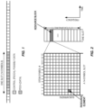
- Data scheduling in NR is typically in slot basis, an example is shown in Figure 1 with a 14-symbol slot, where the first two symbols contain Physical Downlink Control Channel (PDCCH) and the rest contains physical shared data channel, either Physical Downlink Shared Channel (PDSCH) or Physical Uplink Shared Channel (PUSCH).
- PDCCH Physical Downlink Control Channel
- PUSCH Physical Uplink Shared Channel
- Different subcarrier spacing values are supported in NR.
- ⁇ f 15 kHz is the basic subcarrier spacing.
- the slot durations in millisecond at different subcarrier spacings are given by 1 2 ⁇ ms .
- a system bandwidth is divided into resource blocks (RBs); each corresponds to 12 contiguous subcarriers.
- the RBs are numbered starting with 0 from one end of the system bandwidth.
- the basic NR physical time-frequency resource grid is illustrated in Figure 2 , where only one Resource Block (RB) within a 14-symbol slot is shown.
- One OFDM subcarrier during one OFDM symbol interval forms one Resource Element (RE).
- RE Resource Element
- DCI format 1_0 has a smaller size than DCI 1_1 and can be used when a UE is not yet connected to the network while DCI format 1_1 can be used for scheduling MIMO (Multiple-Input-Multiple-Output) transmissions with up to 2 transport blocks (TBs).
- DCI format 1_2 is introduced in NR Release 16 (Rel-16) to support configurable size for certain bit fields in the DCI.
- DCI Frequency Domain Resource Assignment
- TDRA Time Domain Resource Assignment
- MCS Modulation and Coding Scheme
- NDI New data indicator
- RV Redundancy Version
- HARQ process number PUCCH Resource Indicator
- K1 Antenna port(s); and Transmission Configuration Indication (TCI).
- TCI Transmission Configuration Indication
- Several signals can be transmitted from different co-located antenna ports. These signals can have the same large-scale properties, for instance in terms of Doppler shift/spread, average delay spread, average delay, or direction of arrival when measured at the receiver. These antenna ports are then said to be Quasi Co-Located (QCL).
- the network can then signal to the UE that two antenna ports are QCL. If the UE knows that two antenna ports are QCL with respect to a certain parameter (e.g., Doppler spread), the UE can estimate that parameter based on a reference signal transmitted on one of the antenna ports and use that estimate when receiving another reference signal or physical channel on the other antenna port.
- the first antenna port is represented by a measurement reference signal (known as a source RS) such as channel state information reference signal (CSI-RS) and the second antenna port is a DMRS (known as a target RS) for PDSCH reception.
- CSI-RS channel state information reference signal
- Radio Node As used herein, a "radio node” is either a radio access node or a wireless communication device.
- Radio Access Node As used herein, a “radio access node” or “radio network node” or “radio access network node” is any node in a Radio Access Network (RAN) of a cellular communications network that operates to wirelessly transmit and/or receive signals.
- RAN Radio Access Network
- a "core network node” is any type of node in a core network or any node that implements a core network function.
- Some examples of a core network node include, e.g., a Mobility Management Entity (MME), a Packet Data Network Gateway (P-GW), a Service Capability Exposure Function (SCEF), a Home Subscriber Server (HSS), or the like.
- MME Mobility Management Entity
- P-GW Packet Data Network Gateway
- SCEF Service Capability Exposure Function
- HSS Home Subscriber Server
- a core network node examples include a node implementing an Access and Mobility Management Function (AMF), a User Plane Function (UPF), a Session Management Function (SMF), an Authentication Server Function (AUSF), a Network Slice Selection Function (NSSF), a Network Exposure Function (NEF), a Network Function (NF) Repository Function (NRF), a Policy Control Function (PCF), a Unified Data Management (UDM), or the like.
- AMF Access and Mobility Management Function
- UPF User Plane Function
- SMF Session Management Function
- AUSF Authentication Server Function
- NSSF Network Slice Selection Function
- NEF Network Exposure Function
- NRF Network Exposure Function
- NRF Network Exposure Function
- PCF Policy Control Function
- UDM Unified Data Management
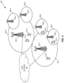
- FIG. 4 illustrates one example of a cellular communications system 400 in which embodiments of the present disclosure may be implemented.
- the cellular communications system 400 is a 5G System (5GS) including a NR RAN or LTE RAN (i.e., Evolved Universal Terrestrial Radio Access (E-UTRA) RAN).
- the RAN includes base stations 402-1 and 402-2, which in 5G NR are referred to as gNBs (e.g., LTE RAN nodes connected to 5G Core (5GC), which are referred to as gn-eNBs), controlling corresponding (macro) cells 404-1 and 404-2.
- gNBs e.g., LTE RAN nodes connected to 5G Core (5GC), which are referred to as gn-eNBs
- 5GC 5G Core
- gn-eNBs controlling corresponding (macro) cells 404-1 and 404-2.
- the base stations 402-1 and 402-2 are generally referred to herein collectively as base stations 402 and individually as base station 402.
- the (macro) cells 404-1 and 404-2 are generally referred to herein collectively as (macro) cells 404 and individually as (macro) cell 404.
- the RAN may also include a number of low power nodes 406-1 through 406-4 controlling corresponding small cells 408-1 through 408-4.
- the low power nodes 406-1 through 406-4 can be small base stations (such as pico or femto base stations) or Remote Radio Heads (RRHs), or the like.
- RRHs Remote Radio Heads
- one or more of the small cells 408-1 through 408-4 may alternatively be provided by the base stations 402.
- the low power nodes 406-1 through 406-4 are generally referred to herein collectively as low power nodes 406 and individually as low power node 406.
- the small cells 408-1 through 408-4 are generally referred to herein collectively as small cells 408 and individually as small cell 408.
- the cellular communications system 400 also includes a core network 410, which in the 5GS is referred to as the 5G Core (5GC).
- the base stations 402 (and optionally the low power nodes 406) are connected to the core network 410.
- the base stations 402 and the low power nodes 406 provide service to wireless communication devices 412-1 through 412-5 in the corresponding cells 404 and 408.
- the wireless communication devices 412-1 through 412-5 are generally referred to herein collectively as wireless communication devices 412 and individually as wireless communication device 412. In the following description, the wireless communication devices 412 are oftentimes UEs, but the present disclosure is not limited thereto.
- DCI format 1_0 has a smaller size than DCI 1_1 and can be used when a UE is not connected to the network while DCI format 1_1 can be used for scheduling MIMO (Multiple-Input-Multiple-Output) transmissions with up to 2 transport blocks (TBs).
- DCI format 1_2 is introduced in NR Release 16 (Rel-16) to support configurable size for certain bit fields in the DCI.
- DCI Frequency Domain Resource Assignment
- TDRA Time Domain Resource Assignment
- MCS Modulation and Coding Scheme
- NDI New data indicator
- RV Redundancy Version
- HARQ process number PUCCH Resource Indicator
- K1 Antenna port(s); and Transmission Configuration Indication (TCI).
- TCI Transmission Configuration Indication
- a UE first detects and decodes PDCCH and if the decoding is successful, it then decodes the corresponding PDSCH based on the decoded DCI carried in the PDCCH.
- the PDSCH decoding status is sent back to the gNB in the form of HARQ Acknowledgment in a PUCCH resource indicated by PRI.
- An example is illustrated in Figure 3 .
- the time offset, T1 between the reception of the DL DCI and the corresponding PDSCH determined by a slot offset and starting symbol of the PDSCH indicated in TDRA in the DCI.
- the time offset, T2 between the reception of the DL DCI and the corresponding HARQ ACK is provided by the PDSCH-to-HARQ_feedback timing indicator in the DCI.
- Each TDRA entry in the TDRA list defines a slot offset K 0 between the PDSCH and the PDCCH scheduling the PDSCH, a start and length indicator SLIV, the PDSCH mapping type (either Type A or Type B) to be assumed in the PDSCH reception, and optionally a repetition number RepNumR16.
- DM-RS Demodulation Reference Signals
- the DM-RS is confined to resource blocks carrying the associated PDSCH and is mapped on allocated Resource Elements (REs) of the OFDM time-frequency grid in NR such that the receiver can efficiently handle time/frequency-selective fading radio channels.
- a PDSCH can have one or multiple DMRS, each associated with an antenna port. The antenna ports used for PDSCH are indicated in DCI scheduling the PDSCH.
- Several signals can be transmitted from different antenna ports in a same location. These signals can have the same large-scale properties, for instance in terms of Doppler shift/spread, average delay spread, or average delay, when measured at the receiver. These antenna ports are then said to be Quasi Co-Located (QCL).
- the network can then signal to the UE that two antenna ports are QCL. If the UE knows that two antenna ports are QCL with respect to a certain parameter (e.g., Doppler spread), the UE can estimate that parameter based on a reference signal transmitted one of the antenna ports and use that estimate when receiving another reference signal or physical channel the other antenna port.
- the first antenna port is represented by a measurement reference signal such as channel state information reference signal (CSI-RS) (known as a source RS) and the second antenna port is a DMRS (known as a target RS) for PDSCH reception.
- CSI-RS channel state information reference signal
- DMRS DMRS
- a QCL relationship between a DMRS in PDCCH and other reference signals is described by a TCI state of a Control Resource Set (CORESET) over which the PDCCH is transmitted.
- CORESET Control Resource Set
- RRC Control Resource Set
- up to three CORESETs per Bandwidth Part (BWP) can be configured for a UE.
- up to five CORESETs per BWP may be configured to a UE, depending on capability.
- downlink data are transmitted over multiple TRPs in which different MIMO layers are transmitted over different TRPs. This is referred to a Non-coherent Joint Transmission (NC-JT).
- N-JT Non-coherent Joint Transmission
- different time/frequency resources may be allocated to different TRPs and one or multiple PDSCH is transmitted over different TRPs.
- Two ways of scheduling multi-TRP transmission are specified in NR Rel-16: multi-PDCCH based multi-TRP transmission and single-PDCCH based multi-TRP transmission.
- the multi-PDCCH based multi-TRP transmission and single-PDCCH based multi-TRP transmission can be used to serve downlink eMBB traffic as well as downlink URLLC traffic to the UE.
- TRP Transmission Points
- a UE In cases where a UE is not scheduled with all DMRS ports within a CDM group, there may be another UE simultaneously scheduled, using the remaining ports of that CDM group. The UE can then estimate the channel for that other UE (thus an interfering signal) in order to perform coherent interference suppression. Hence, this is useful in MU-MIMO scheduling and UE interference suppression.
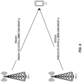
- Figure 6 illustrates an example relationship between TCI states and DM-RS CDM groups for a multiple-PDCCH multi-TRP scenario.
- PDSCH1 is associated with TCI State p
- PDSCH 2 is associated with TCI state q .
- the PDSCH DM-RSs from the different TRPs also belong to different DM-RS CDM groups as they are not quasi-collocated.
- the DMRS for PDSCH1 belongs to CDM group u while the DMRS for PDSCH2 belongs to CDM group v.
- TRP Transmission Points
- the UE may assume that the TCI states for the PDSCH are given by the TCI states corresponding to the lowest codepoint among the TCI codepoints containing two different TCI states. In this case, the two TCI states are the default TCI states.
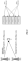
- NZP CSI-RS can be configured to be transmitted in certain REs in a slot and certain slots.
- Figure 12 shows an example of CSI-RS REs for 12 antenna ports, where 1RE per RB per port is shown.
- the UE when AP CSI-RS is in the same symbols as PDSCH2, the UE applies the QCL assumption of PDSCH2 (given by the 2 nd indicated TCI state in DCI) when receiving the AP CSI-RS. Stated in other words, the UE receives the AP CSI-RS using the same receive beam as the one used to receive PDSCH2 whose spatial QCL properties are given by the 2 nd indicated TCI state in DCI.
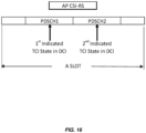
- a UE is configured to receive PDSCH according to "TDMSchemeA" and is indicated with 2 TCI states in the DCI.
- the scheduling offset from the last symbol of the PDCCH to the first symbol of PDSCH1 is smaller than the threshold timeDurationForQCL but the scheduling offset from the last symbol of the PDCCH to the first symbol of PDSCH2 is larger than or equal to the threshold.
- the 1 st default TCI state is applied to PDSCH1 and the 2 nd indicated TCI state is applied to PDSCH2.
- the default TCI states for the PDSCH are given by the TCI states corresponding to the lowest codepoint among the TCI codepoints containing two different TCI states, according to the NR Rel-16 specification. Hence, 1 st default TCI state is defined as the first of the two different TCI states corresponding to the lowest such codepoint.
- the UE when AP CSI-RS is in the same symbols as PDSCH1, the UE applies the QCL assumption of PDSCH1 (given by the 1 st default TCI state) when receiving the AP CSI-RS. Stated in other words, the UE receives the AP CSI-RS using the same receive beam as the one used to receive PDSCH1 whose spatial QCL properties are given by the 1 st default TCI state.
- the UE when AP CSI-RS is in the same symbols as PDSCH2, the UE applies the QCL assumption of PDSCH2 (given by the 2 nd default TCI state) when receiving the AP CSI-RS. Stated in other words, the UE receives the AP CSI-RS using the same receive beam as the one used to receive PDSCH2 whose spatial QCL properties are given by the 2 nd default TCI state.
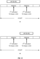
- Embodiment 4 for scenario when AP CSI-RS collides with PDSCH scheduled according to single-PDCCH based NC-JT scheme and scheduling offset above a threshold.
- a UE is configured to receive PDSCH according to single-PDCCH based NC-JT scheme and is indicated with two TCI states in the DCI where the two indicated TCI states are used to receive different sets of layers corresponding to the PDSCH (i.e., first set of layers correspond to 1 st TCI state and second set of layers correspond to 2 nd TCI state).
- first set of layers correspond to 1 st TCI state
- second set of layers correspond to 2 nd TCI state
- an aperiodic CSI-RS (AP CSI-RS) is triggered to the UE by another DCI with scheduling offset between the last symbol of the PDCCH carrying the triggering DCI and the first symbol of the aperiodic CSI-RS resources is smaller than the UE reported threshold beamSwitchTiming.
- Figure 21 illustrates a first example of Embodiment 4 considering AP CSI-RS collision with PDSCH scheduled according to single-PDCCH based NC-JT scheme, where the 1 st TCI state is assumed for the AP CSI-RS.
- the aperiodic CSI-RS overlaps with the PDSCH symbols as shown in Figure 21 .
- the UE applies the QCL assumption given by the 1st indicated TCI state in DCI for the PDSCH when receiving the 1 st AP CSI-RS. Stated in other words, the UE receives the 1 st AP CSI-RS using the same receive beam as the one used to receive PDSCH whose spatial QCL properties are given by the 1st indicated TCI state in DCI.
- the UE applies the QCL assumption given by the 2nd indicated TCI state in DCI for the PDSCH when receiving the 2 nd AP CSI-RS. Stated in other words, the UE receives the 2 nd AP CSI-RS using the same receive beam as the one used to receive PDSCH whose spatial QCL properties are given by the 2nd indicated TCI state in DCI.
- the 1 st and 2 nd AP CSI-RS resources are defined using either the CSI-RS resource IDs or CSI-RS resource set IDs (i.e., NZP-CSI-RS-ResourceSetId ) to which the AP CSI-RS resources belong to. For instance, if the two AP CSI-RS resources are in different CSI-RS resource set IDs, then the AP CSI-RS resource with the smallest NZP-CSI-RS-ResourceSetId is the 1 st AP CSI-RS resource and the AP CSI-RS resource with the largest NZP-CSI-RS-ResourceSetId is the 2 nd AP CSI-RS resource. Similar definition of 1 st and 2 nd AP CSI-RS resource can be achieved by using CSI-RS resource IDs in place of CSI-RS resource set IDs.
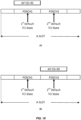
- Embodiment 5 for scenario when AP CSI-RS collides with PDSCH scheduled according to single-PDCCH based NC-JT scheme and scheduling offset below a threshold.
- a UE is configured to receive PDSCH according to single-PDCCH based NC-JT scheme and is indicated with 2 TCI states in the DCI where the 2 default TCI states are used to receive different layers corresponding to the PDSCH. This corresponds to the case where the scheduling offset from the last symbol of the PDCCH to the first symbol of the PDSCH is smaller than the threshold timeDurationForQCL.
- the default TCI states for the PDSCH are given by the TCI states corresponding to the lowest codepoint among the TCI codepoints containing two different TCI states, according to the NR Rel-16 specification.
- an Aperiodic CSI-RS (AP CSI-RS) is triggered to the UE with scheduling offset between the last symbol of the PDCCH carrying the triggering DCI and the first symbol of the aperiodic CSI-RS resources is smaller than the UE reported threshold beamSwitchTiming.
- Figure 23 illustrates a first example of Embodiment 5 considering AP CSI-RS collision with PDSCH scheduled according to single-PDCCH based NC-JT scheme, where the 1 st default TCI state is assumed for the AP CSI-RS.
- the aperiodic CSI-RS overlaps with the PDSCH symbols as shown in Figure 23 .
- the UE when AP CSI-RS is in the same symbols as PDSCH as shown in Figure 23 , the UE applies the QCL assumption given by the 1st default TCI state in DCI for the PDSCH when receiving the AP CSI-RS. Stated in other words, the UE receives the AP CSI-RS using the same receive beam as the one used to receive PDSCH whose spatial QCL properties are given by the 1st default TCI state.
- two AP CSI-RSs are triggered to the UE with scheduling offset between the last symbol of the PDCCH carrying the triggering DCI and the first symbol(s) of the aperiodic CSI-RS resources is smaller than the UE reported threshold beamSwitchTiming.
- Figure 24 illustrates a second example of Embodiment 5 considering AP CSI-RS collision with PDSCH scheduled according to single-PDCCH based NC-JT scheme, where the 1 st and 2 nd default TCI states are assumed for the 1 st and 2 nd AP CSI-RS, respectively.
- the two aperiodic CSI-RSs overlap with the PDSCH symbols as shown in Figure 24 .
- the UE applies the QCL assumption given by the 1st default TCI state for the PDSCH when receiving the 1 st AP CSI-RS. Stated in other words, the UE receives the 1 st AP CSI-RS using the same receive beam as the one used to receive PDSCH whose spatial QCL properties are given by the 1st default TCI state in DCI.
- the UE applies the QCL assumption given by the 2nd default TCI state for the PDSCH when receiving the 2 nd AP CSI-RS. Stated in other words, the UE receives the 2 nd AP CSI-RS using the same receive beam as the one used to receive PDSCH whose spatial QCL properties are given by the 2nd indicated TCI state in DCI.
- the 1 st and 2 nd AP CSI-RS resources are defined using either the CSI-RS resource IDs or CSI-RS resource set IDs (i.e., NZP-CSI-RS-ResourceSetId ) to which the AP CSI-RS resources belong to. For instance, if the two AP CSI-RS resources are in different CSI-RS resource set IDs, then the AP CSI-RS resource with the smallest NZP-CSI-RS-ResourceSetId is the 1 st AP CSI-RS resource and the AP CSI-RS resource with the largest NZP-CSI-RS-ResourceSetId is the 2 nd AP CSI-RS resource. Similar definition of 1 st and 2 nd AP CSI-RS resource can be achieved by using CSI-RS resource IDs in place of CSI-RS resource set IDs.
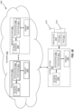
- FIG. 25 is a schematic block diagram of a radio access node 2500 according to some embodiments of the present disclosure.
- the radio access node 2500 may be, for example, a base station 402 or 406 or a network node that implements all or part of the functionality of the base station 402 or gNB described herein.
- the radio access node 2500 includes a control system 2502 that includes one or more processors 2504 (e.g., Central Processing Units (CPUs), Application Specific Integrated Circuits (ASICs), Field Programmable Gate Arrays (FPGAs), and/or the like), memory 2506, and a network interface 2508.
- the one or more processors 2504 are also referred to herein as processing circuitry.
- the radio access node 2500 may include one or more radio units 2510 that each includes one or more transmitters 2512 and one or more receivers 2514 coupled to one or more antennas 2516.
- the radio units 2510 may be referred to or be part of radio interface circuitry.
- the radio unit(s) 2510 is external to the control system 2502 and connected to the control system 2502 via, e.g., a wired connection (e.g., an optical cable).
- the radio unit(s) 2510 and potentially the antenna(s) 2516 are integrated together with the control system 2502.
- the one or more processors 2504 operate to provide one or more functions of a radio access node 2500 as described herein.
- the function(s) are implemented in software that is stored, e.g., in the memory 2506 and executed by the one or more processors 2504.
- Figure 26 is a schematic block diagram that illustrates a virtualized embodiment of the radio access node 2500 according to some embodiments of the present disclosure. This discussion is equally applicable to other types of network nodes. Further, other types of network nodes may have similar virtualized architectures. Again, optional features are represented by dashed boxes.
- a "virtualized" radio access node is an implementation of the radio access node 2500 in which at least a portion of the functionality of the radio access node 2500 is implemented as a virtual component(s) (e.g., via a virtual machine(s) executing on a physical processing node(s) in a network(s)).
- the radio access node 2500 may include the control system 2502 and/or the one or more radio units 2510, as described above.
- the control system 2502 may be connected to the radio unit(s) 2510 via, for example, an optical cable or the like.
- the radio access node 2500 includes one or more processing nodes 2600 coupled to or included as part of a network(s) 2602.
- functions 2610 of the radio access node 2500 described herein are implemented at the one or more processing nodes 2600 or distributed across the one or more processing nodes 2600 and the control system 2502 and/or the radio unit(s) 2510 in any desired manner.
- some or all of the functions 2610 of the radio access node 2500 described herein are implemented as virtual components executed by one or more virtual machines implemented in a virtual environment(s) hosted by the processing node(s) 2600.
- additional signaling or communication between the processing node(s) 2600 and the control system 2502 is used in order to carry out at least some of the desired functions 2610.
- the control system 2502 may not be included, in which case the radio unit(s) 2510 communicates directly with the processing node(s) 2600 via an appropriate network interface(s).
- a computer program including instructions which, when executed by at least one processor, causes the at least one processor to carry out the functionality of radio access node 2500 or a node (e.g., a processing node 2600) implementing one or more of the functions 2610 of the radio access node 2500 in a virtual environment according to any of the embodiments described herein is provided.
- a carrier comprising the aforementioned computer program product is provided. The carrier is one of an electronic signal, an optical signal, a radio signal, or a computer readable storage medium (e.g., a non-transitory computer readable medium such as memory).
- FIG 27 is a schematic block diagram of the radio access node 2500 according to some other embodiments of the present disclosure.
- the radio access node 2500 includes one or more modules 2700, each of which is implemented in software.
- the module(s) 2700 provide the functionality of the radio access node 2500 described herein. This discussion is equally applicable to the processing node 2600 of Figure 26 where the modules 2700 may be implemented at one of the processing nodes 2600 or distributed across multiple processing nodes 2600 and/or distributed across the processing node(s) 2600 and the control system 2502.
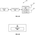
- FIG. 28 is a schematic block diagram of a wireless communication device 2800 according to some embodiments of the present disclosure.
- the wireless communication device 2800 includes one or more processors 2802 (e.g., CPUs, ASICs, FPGAs, and/or the like), memory 2804, and one or more transceivers 2806 each including one or more transmitters 2808 and one or more receivers 2810 coupled to one or more antennas 2812.
- the transceiver(s) 2806 includes radio-front end circuitry connected to the antenna(s) 2812 that is configured to condition signals communicated between the antenna(s) 2812 and the processor(s) 2802, as will be appreciated by on of ordinary skill in the art.
- the processors 2802 are also referred to herein as processing circuitry.
- the transceivers 2806 are also referred to herein as radio circuitry.
- the functionality of the wireless communication device 2800 described above may be fully or partially implemented in software that is, e.g., stored in the memory 2804 and executed by the processor(s) 2802.
- the wireless communication device 2800 may include additional components not illustrated in Figure 28 such as, e.g., one or more user interface components (e.g., an input/output interface including a display, buttons, a touch screen, a microphone, a speaker(s), and/or the like and/or any other components for allowing input of information into the wireless communication device 2800 and/or allowing output of information from the wireless communication device 2800), a power supply (e.g., a battery and associated power circuitry), etc.
- user interface components e.g., an input/output interface including a display, buttons, a touch screen, a microphone, a speaker(s), and/or the like and/or any other components for allowing input of information into the wireless communication device 2800 and/or allowing output of information from the wireless communication device 2800
- a power supply e.g., a battery and associated power circuitry
- a computer program including instructions which, when executed by at least one processor, causes the at least one processor to carry out the functionality of the wireless communication device 2800 according to any of the embodiments described herein is provided.
- a carrier comprising the aforementioned computer program product is provided.
- the carrier is one of an electronic signal, an optical signal, a radio signal, or a computer readable storage medium (e.g., a non-transitory computer readable medium such as memory).
- FIG. 29 is a schematic block diagram of the wireless communication device 2800 according to some other embodiments of the present disclosure.
- the wireless communication device 2800 includes one or more modules 2900, each of which is implemented in software.
- the module(s) 2900 provide the functionality of the wireless communication device 2800 described herein.
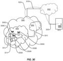
- a communication system includes a telecommunication network 3000, such as a 3GPP-type cellular network, which comprises an access network 3002, such as a RAN, and a core network 3004.
- the access network 3002 comprises a plurality of base stations 3006A, 3006B, 3006C, such as Node Bs, eNBs, gNBs, or other types of wireless Access Points (APs), each defining a corresponding coverage area 3008A, 3008B, 3008C.
- Each base station 3006A, 3006B, 3006C is connectable to the core network 3004 over a wired or wireless connection 3010.
- the intermediate network 3022 may be one of, or a combination of more than one of, a public, private, or hosted network; the intermediate network 3022, if any, may be a backbone network or the Internet; in particular, the intermediate network 3022 may comprise two or more sub-networks (not shown).
- the communication system 3100 further includes the UE 3114 already referred to.
- the UE's 3114 hardware 3134 may include a radio interface 3136 configured to set up and maintain a wireless connection 3126 with a base station serving a coverage area in which the UE 3114 is currently located.
- the hardware 3134 of the UE 3114 further includes processing circuitry 3138, which may comprise one or more programmable processors, ASICs, FPGAs, or combinations of these (not shown) adapted to execute instructions.
- the UE 3114 further comprises software 3140, which is stored in or accessible by the UE 3114 and executable by the processing circuitry 3138.
- the software 3140 includes a client application 3142.
- the host computer 3102, the base station 3118, and the UE 3114 illustrated in Figure 31 may be similar or identical to the host computer 3016, one of the base stations 3006A, 3006B, 3006C, and one of the UEs 3012, 3014 of Figure 30 , respectively.
- the inner workings of these entities may be as shown in Figure 31 and independently, the surrounding network topology may be that of Figure 30 .
- a measurement procedure may be provided for the purpose of monitoring data rate, latency, and other factors on which the one or more embodiments improve.
- the measurement procedure and/or the network functionality for reconfiguring the OTT connection 3116 may be implemented in the software 3110 and the hardware 3104 of the host computer 3102 or in the software 3140 and the hardware 3134 of the UE 3114, or both.
- sub-step 3406 (which may be optional) of step 3402
- the UE executes a client application which provides the user data in reaction to the received input data provided by the host computer.
- the executed client application may further consider user input received from the user.
- the UE initiates, in sub-step 3408 (which may be optional), transmission of the user data to the host computer.
- step 3410 of the method the host computer receives the user data transmitted from the UE, in accordance with the teachings of the embodiments described throughout this disclosure.
- FIG 35 is a flowchart illustrating a method implemented in a communication system, in accordance with one embodiment.
- the communication system includes a host computer, a base station, and a UE which may be those described with reference to Figures 30 and 31 .
- the base station receives user data from the UE.
- the base station initiates transmission of the received user data to the host computer.
- the host computer receives the user data carried in the transmission initiated by the base station.
- any appropriate steps, methods, features, functions, or benefits disclosed herein may be performed through one or more functional units or modules of one or more virtual apparatuses.
- Each virtual apparatus may comprise a number of these functional units.
- These functional units may be implemented via processing circuitry, which may include one or more microprocessor or microcontrollers, as well as other digital hardware, which may include Digital Signal Processor (DSPs), special-purpose digital logic, and the like.
- the processing circuitry may be configured to execute program code stored in memory, which may include one or several types of memory such as Read Only Memory (ROM), Random Access Memory (RAM), cache memory, flash memory devices, optical storage devices, etc.
- Program code stored in memory includes program instructions for executing one or more telecommunications and/or data communications protocols as well as instructions for carrying out one or more of the techniques described herein.
- the processing circuitry may be used to cause the respective functional unit to perform corresponding functions according one or more embodiments of the present disclosure.
Landscapes
- Engineering & Computer Science (AREA)
- Signal Processing (AREA)
- Computer Networks & Wireless Communication (AREA)
- Mobile Radio Communication Systems (AREA)
Claims (19)
- Verfahren, das von einer drahtlosen Vorrichtung durchgeführt wird, zum Bestimmen von Übertragungskonfigurationsindikations-, TCI-, Zuständen zum Empfangen eines oder mehrerer aperiodischer, AP, Kanalzustandsinformations-Referenzsignale, CSI-RSs, wobei das Verfahren umfasst:Empfangen (1302) einer Downlink-Steuerinformation, DCI, in einem physikalischen Downlink-Steuerkanal, PDCCH, Auslösen eines oder mehrerer AP CSI-RSs in einem oder mehreren Symbolen mit einem ersten Zeitversatz zwischen einem letzten Symbol des PDCCH und dem ersten Symbol des einen oder der mehreren Symbole, das oder die die AP CSI-RSs umfasst oder umfassen, wobei der Zeitversatz kleiner als ein erster Schwellenwert ist;Bestimmen (1304) einer Quasi-Co-Lokalisierungs-, QCL-, Annahme zum Empfangen des einen oder der mehreren AP CSI-RSs auf der Grundlage einer Vielzahl von TCI-Zuständen, die mit einer oder mehreren Downlink-Übertragungen assoziiert sind, die von der DCI in demselben einen oder denselben mehreren Symbolen wie die einen oder mehreren AP CSI-RSs geplant werden, wobei die Vielzahl von TCI-Zuständen in einer DCI angegeben wird oder werden, die die eine oder mehreren Downlink-Übertragungen plant, wobei, wenn der Zeitversatz kleiner als der erste Schwellenwert ist, die bestimmte QCL-Annahme eine QCL-Annahme ist, die durch einen TCI-Zustand der Vielzahl von TCI-Zuständen gegeben ist, die durch die DCI angegeben werden, die die eine oder mehreren Downlink-Übertragungen in einem Symbol desselben einen oder derselben mehreren Symbole plant, das oder die zum Empfangen des einen oder der mehreren AP CSI-RSs verwendet wird oder werden; undEmpfangen (1300) des einen oder der mehreren AP CSI-RSs in dem einen oder den mehreren Symbolen unter Verwendung der bestimmten QCL-Annahme.
- Verfahren nach Anspruch 1, wobei die eine oder mehreren Downlink-Übertragungen eine oder mehrere physikalische gemeinsam genutzte Downlink-Kanal-, PDSCH-, Übertragungen umfasst oder umfassen;
wobei ein zweiter Zeitversatz zwischen einem ersten Symbol des PDCCH, der die DCI trägt, die den einen oder die mehreren PDSCH plant, und einem ersten Symbol des PDSCH größer oder gleich einem zweiten Schwellenwert ist. - Verfahren nach Anspruch 1 oder 2,- wobei die eine oder mehreren Downlink-Übertragungen eine oder mehrere PDSCH-Wiederholungen im Zeitbereich oder im Frequenzbereich ist oder sind, wobei optional die eine oder mehreren Downlink-Übertragungen gemäß einem der Schemata "TDMSchemeA", "FDMSchemeB" oder "FDMSchemeA" erfolgt oder erfolgen;
und/oder- wobei die eine oder mehreren Downlink-Übertragungen ein oder mehrere Sätze von Schichten eines PDSCH ist oder sind, wobei jeder Satz von Schichten mit einem der Vielzahl von TCI-Zuständen assoziiert ist, wobei die drahtlose Vorrichtung konfiguriert ist, um einen PDSCH gemäß einem Einzel-PDCCH-basierten NC-JT-Schema zu empfangen. - Verfahren nach einem der Ansprüche 1 bis 3,- wobei die Vielzahl von TCI-Zuständen einen ersten und einen zweiten TCI-Zustand umfasst;
und/oder- wobei das eine oder die mehreren Symbole ein oder mehrere Orthogonale Frequenzteilungs-Multiplexing-, OFDM-, Symbole ist oder sind;
und/oder- wobei der erste Schwellenwert einen von der drahtlosen Vorrichtung gemeldeten beamSwitchTiming-Wert umfasst. - Verfahren nach Anspruch 2, wobei der zweite Schwellenwert ein von der drahtlosen Vorrichtung gemeldeter timeDurationForQCL-Wert ist.
- Verfahren nach einem der Ansprüche 1 bis 5,- wobei die bestimmte QCL-Annahme eine QCL-Annahme ist, die durch einen ersten angegebenen TCI-Zustand in einer DCI für einen gemeinsam genutzten physikalischen Downlink-Kanal, PDSCH, in einem Symbol zum Empfangen des einen oder der mehreren AP CSI-RSs in demselben einen oder denselben mehreren Symbolen gegeben ist, wenn die eine oder mehreren Downlink-Übertragungen ein oder mehrere Sätze von Schichten des PDSCH ist oder sind, wobei jeder Satz von Schichten mit einem der mehreren TCI-Zustände assoziiert ist;
oder- wobei die bestimmte QCL-Annahme eine QCL-Annahme ist, die durch einen TCI-Zustand einer oder mehrerer Downlink-PDSCH-Übertragungen in einem Symbol zum Empfangen des einen oder der mehreren AP CSI-RSs in demselben einen oder denselben mehreren Symbolen gegeben ist, wenn die eine oder mehreren Downlink-PDSCH-Übertragungen eine oder mehrere PDSCH-Wiederholungen im Zeitbereich ist oder sind und jede der einen oder mehreren PDSCH-Übertragungen mit einem der mehreren TCI-Zustände assoziiert ist;
oder- wobei die bestimmte QCL-Annahme eine QCL-Annahme ist, die durch den ersten TCI-Zustand der Vielzahl von TCI-Zuständen zum Empfangen des einen oder der mehreren AP CSI-RSs gegeben ist. - Verfahren nach Anspruch 2, wobei ein zweiter Versatz kleiner als der Schwellenwert timeDurationForQCL ist.
- Verfahren nach einem der Ansprüche 1 bis 7, wobei die Vielzahl von TCI-Zuständen einen ersten und einen zweiten Voreinstellungs-TCI-Zustand umfasst, wobei der erste und der zweite Voreinstellungs-TCI-Zustand mit einem Codepunkt eines TCI-Felds in einer DCI mit einem niedrigsten Codepunktwert assoziiert sind;
wobei optional:ein einzelner ausgelöster AP CSI-RS sich in denselben Symbolen wie eine Downlink-PDSCH-Übertragung befindet; undwobei die bestimmte QCL-Annahme eine QCL-Annahme ist, die durch einen ersten Voreinstellungs-TCI-Zustand des PDSCH zum Empfangen des AP CSI-RS gegeben ist. - Verfahren nach Anspruch 7 oder 8, wobei:zwei ausgelöste AP CSI-RSs sich in denselben Symbolen wie ein PDSCH befinden, der mit dem ersten und zweiten TCI-Zustand assoziiert ist; unddie bestimmte QCL-Annahme eine QCL-Annahme ist, die durch den ersten bzw. den zweiten Voreinstellungs-TCI-Zustand des PDSCH zum Empfangen des ersten bzw. zweiten AP CSI-RS gegeben ist.
- Verfahren, das von einer Basisstation durchgeführt wird, um Übertragungskonfigurationsindikations-, TCI-, Zustände zum Empfangen von einem oder mehreren aperiodischen, AP, Kanalzustandsinformations-Referenzsignalen, CSI-RSs, anzugeben, wobei das Verfahren umfasst:Übertragen, an eine drahtlose Vorrichtung, einer Downlink-Steuerinformation, DCI, in einem physikalischen Steuerkanal, PDCCH, Auslösen des Empfangs eines oder mehrerer AP CSI-RSs, das oder die in einem oder mehreren Symbolen an die drahtlose Vorrichtung zu übertragen ist oder sind, wobei eine oder mehrere Downlink-Übertragungen, die mit zwei TCI-Zuständen assoziiert ist oder sind, ebenfalls in denselben Symbolen zu übertragen sind, wobei ein erster Zeitversatz zwischen dem PDCCH und dem einen oder den mehreren AP CSI-RSs kleiner als ein erster Schwellenwert ist;Bestimmen einer Quasi-Co-Lokalisierungs-, QCL-, Annahme zum Übertragen des einen oder der mehreren AP CSI-RSs basierend auf TCI-Zuständen der einen oder mehreren Downlink-Übertragungen, wobei die Vielzahl von TCI-Zuständen in der DCI-Planung der einen oder mehreren Downlink-Übertragungen angegeben wird, wobei, wenn der Zeitversatz kleiner als der erste Schwellenwert ist, die bestimmte QCL-Annahme eine QCL-Annahme ist, die durch einen TCI-Zustand der Vielzahl von TCI-Zuständen gegeben ist, die durch die DCI angegeben wird, die die eine oder mehreren Downlink-Übertragungen in einem Symbol desselben einen oder derselben mehreren Symbole plant, das oder die zum Empfangen des einen oder der mehreren AP CSI-RSs verwendet wird oder werden; undÜbertragen (1400), an die drahtlose Vorrichtung, des einen oder der mehreren AP CSI-RSs in dem einen oder den mehreren Symbolen gemäß der QCL-Annahme.
- Verfahren nach Anspruch 10, wobei die eine oder mehreren Downlink-Übertragungen physikalische gemeinsam genutzte Downlink-Kanal-, PDSCH-, Übertragung oder Übertragungen umfassen;wobei optional ein zweiter Zeitversatz zwischen dem PDCCH und dem PDSCH größer oder gleich einem zweiten Schwellenwert ist;wobei optional der erste und zweite Schwellenwert an die drahtlose Vorrichtung signalisiert werden.
- Verfahren nach Anspruch 10 oder 11,- wobei die eine oder mehreren Downlink-Übertragungen eine oder mehrere PDSCH-Wiederholungen im Zeitbereich ist oder sind;
und/oder- wobei die einen oder mehreren Downlink-Übertragungen ein oder mehrere Sätze von Schichten eines PDSCH ist oder sind, wobei jeder Satz von Schichten mit einem der zwei TCI-Zustände assoziiert ist, wobei die drahtlose Vorrichtung konfiguriert ist, um einen PDSCH gemäß einem Einzel-PDCCH-basierten NC-JT-Schema zu empfangen.
und/oder- wobei die zwei TCI-Zustände in der DCI angegeben werden, die die eine oder mehreren PDSCH-Übertragungen plant;
und/oder- wobei die zwei TCI-Zustände einen ersten und einen zweiten TCI-Zustand umfassen;
und/oder- wobei das eine oder die mehreren Symbole ein oder mehrere Orthogonale Frequenzteilungs-Multiplexing-, OFDM-, Symbole ist oder sind;
und/oder- wobei der erste Schwellenwert einen von der drahtlosen Vorrichtung gemeldeten beamSwitchTiming-Wert umfasst. - Verfahren nach Anspruch 11, wobei der zweite Schwellenwert einen von der drahtlosen Vorrichtung gemeldeten timeDurationForQCL-Wert umfasst.
- Verfahren nach einem der Ansprüche 10 bis 13,- wobei die QCL-Annahme eine QCL-Annahme ist, die durch einen ersten TCI-Zustand eines PDSCH zum Übertragen des einen oder der mehreren AP CSI-RSs gegeben ist, wenn die eine oder mehreren Downlink-Übertragungen ein oder mehrere Sätze von Schichten des PDSCH ist oder sind und jeder Satz von Schichten mit einem der zwei TCI-Zustände assoziiert ist;
oder- wobei die QCL-Annahme eine QCL-Annahme ist, die durch einen TCI-Zustand einer oder mehrerer Downlink-PDSCH-Übertragungen in einem Symbol zum Übertragen des einen oder der mehreren AP CSI-RSs in demselben Symbol gegeben ist, wenn die eine oder mehreren Downlink-PDSCH-Übertragungen eine oder mehrere PDSCH-Wiederholungen im Zeitbereich ist oder sind und jede der einen oder mehreren PDSCH-Übertragungen mit einem der zwei TCI-Zustände assoziiert ist;
oder- wobei die QCL-Annahme eine QCL-Annahme ist, die durch einen ersten TCI-Zustand der zwei TCI-Zustände zum Übertragen des einen oder der mehreren AP CSI-RSs gegeben ist. - Verfahren nach Anspruch 13, wobei der zweite Versatz davon kleiner als der zweite Schwellenwert timeDurationForQCL ist.
- Verfahren nach einem der Ansprüche 10 bis 15,- wobei die zwei TCI-Zustände einen ersten und einen zweiten Voreinstellungs-TCI-Zustand umfassen, wobei der erste und der zweite Voreinstellungs-TCI-Zustand mit einem Codepunkt eines TCI-Felds in einer DCI mit einem niedrigsten Codepunktwert assoziiert sind;
und/oder- wobei die Voreinstellungs-TCI-Zustände für die eine oder mehreren Downlink-Übertragungen durch die TCI-Zustände gegeben sind, die dem niedrigsten Codepunkt unter den TCI-Codepunkten entsprechen, die zwei verschiedene TCI-Zustände umfassen. - Verfahren nach Anspruch 15 oder 16,- wobei ein einzelnes ausgelöstes AP CSI-RS in denselben Symbolen wie ein PDSCH ist; und die QCL-Annahme eine QCL-Annahme ist, die durch einen ersten Voreinstellungs-TCI-Zustand für den PDSCH gegeben ist, wenn das AP CSI-RS übertragen wird;
und/oder- wobei zwei ausgelöste AP CSI-RSs in denselben Symbolen wie ein PDSCH sind; und die QCL-Annahme eine QCL-Annahme ist, die durch den ersten bzw. zweiten Voreinstellungs-TCI-Zustand für den PDSCH gegeben ist, wenn das erste bzw. zweite AP CSI-RS übertragen werden. - Drahtlose Vorrichtung (2800) zum Aktivieren von Übertragungskonfigurationsindikations-, TCI-, Zuständen, die umfasst:einen oder mehrere Sender (2808);einen oder mehrere Empfänger (2810); undeine Verarbeitungsschaltung (2802), die mit dem einen oder den mehreren Sendern (2808) und dem einen oder den mehreren Empfängern (2810) assoziiert ist, wobei die Verarbeitungsschaltung (2802) konfiguriert ist, um die drahtlose Vorrichtung (2800) zu veranlassen, das Verfahren nach einem der Ansprüche 1 bis 9 durchzuführen.
- Basisstation (2500) zum Aktivieren von Übertragungskonfigurationsindikations-, TCI-, Zuständen, die umfasst:einen oder mehrere Sender (2512);einen oder mehrere Empfänger (2514); undeine Verarbeitungsschaltung (2504), die mit dem einen oder den mehreren Sendern (2512) und dem einen oder den mehreren Empfängern (2514) assoziiert ist, wobei die Verarbeitungsschaltung (2504) konfiguriert ist, um die Basisstation (2500) zu veranlassen, das Verfahren nach einem der Ansprüche 10 bis 17 durchzuführen.
Priority Applications (1)
| Application Number | Priority Date | Filing Date | Title |
|---|---|---|---|
| EP25187831.0A EP4641966A3 (de) | 2020-04-10 | 2021-04-12 | Empfang von zeitüberlappenden downlink-referenzsignalen und kanälen |
Applications Claiming Priority (2)
| Application Number | Priority Date | Filing Date | Title |
|---|---|---|---|
| US202063008386P | 2020-04-10 | 2020-04-10 | |
| PCT/IB2021/053016 WO2021205417A1 (en) | 2020-04-10 | 2021-04-12 | Receiving time overlapping downlink reference signals and channels |
Related Child Applications (1)
| Application Number | Title | Priority Date | Filing Date |
|---|---|---|---|
| EP25187831.0A Division EP4641966A3 (de) | 2020-04-10 | 2021-04-12 | Empfang von zeitüberlappenden downlink-referenzsignalen und kanälen |
Publications (3)
| Publication Number | Publication Date |
|---|---|
| EP4133664A1 EP4133664A1 (de) | 2023-02-15 |
| EP4133664B1 true EP4133664B1 (de) | 2025-07-09 |
| EP4133664C0 EP4133664C0 (de) | 2025-07-09 |
Family
ID=75539737
Family Applications (2)
| Application Number | Title | Priority Date | Filing Date |
|---|---|---|---|
| EP25187831.0A Pending EP4641966A3 (de) | 2020-04-10 | 2021-04-12 | Empfang von zeitüberlappenden downlink-referenzsignalen und kanälen |
| EP21719289.7A Active EP4133664B1 (de) | 2020-04-10 | 2021-04-12 | Empfang von zeitüberlappenden downlink-referenzsignalen und kanälen |
Family Applications Before (1)
| Application Number | Title | Priority Date | Filing Date |
|---|---|---|---|
| EP25187831.0A Pending EP4641966A3 (de) | 2020-04-10 | 2021-04-12 | Empfang von zeitüberlappenden downlink-referenzsignalen und kanälen |
Country Status (5)
| Country | Link |
|---|---|
| US (1) | US20230179354A1 (de) |
| EP (2) | EP4641966A3 (de) |
| JP (1) | JP7648648B2 (de) |
| CN (1) | CN115398848B (de) |
| WO (1) | WO2021205417A1 (de) |
Families Citing this family (10)
| Publication number | Priority date | Publication date | Assignee | Title |
|---|---|---|---|---|
| CN111132314B (zh) * | 2018-10-30 | 2022-06-24 | 维沃移动通信有限公司 | 非周期信道状态信息参考信号配置方法、网络设备及终端 |
| CN115812318B (zh) * | 2020-05-14 | 2024-11-01 | 株式会社Ntt都科摩 | 终端、无线通信方法以及基站 |
| US11895058B2 (en) * | 2020-09-04 | 2024-02-06 | Qualcomm Incorporated | Methods for scheduling offset determination in ultra wide bandwidth beamforming systems |
| US12199908B2 (en) * | 2021-05-11 | 2025-01-14 | Qualcomm Incorporated | Aperiodic (AP) channel state information (CSI) quasi-colocation (QCL) assumption with single frequency network (SFN) physical downlink control channel (PDCCH) transmission |
| EP4391410A4 (de) * | 2021-08-19 | 2025-07-30 | Ntt Docomo Inc | Endgerät, drahtloskommunikationsverfahren und basisstation |
| US20240313847A1 (en) * | 2021-09-10 | 2024-09-19 | Qualcomm Incorporated | Receiving a plurality of physical downlink shared channels using quasi co-location assumptions |
| KR20230107097A (ko) * | 2022-01-07 | 2023-07-14 | 엘지전자 주식회사 | 무선 통신 시스템에서 통신을 수행하는 방법 및 장치 |
| WO2024031547A1 (zh) * | 2022-08-11 | 2024-02-15 | 富士通株式会社 | 非周期参考信号的接收和发送方法以及装置 |
| CN117939513A (zh) * | 2022-10-26 | 2024-04-26 | 上海朗帛通信技术有限公司 | 一种被用于无线通信的方法和装置 |
| EP4693937A2 (de) * | 2023-04-06 | 2026-02-11 | LG Electronics Inc. | Vorrichtung und verfahren zur meldung von kanalstatusinformationen auf basis von subkonfigurationen in einem drahtloskommunikationssystem |
Family Cites Families (6)
| Publication number | Priority date | Publication date | Assignee | Title |
|---|---|---|---|---|
| US10506587B2 (en) * | 2017-05-26 | 2019-12-10 | Samsung Electronics Co., Ltd. | Method and apparatus for beam indication in next generation wireless systems |
| EP4243325B1 (de) * | 2017-11-15 | 2026-02-18 | InterDigital Patent Holdings, Inc. | Beamverwaltung in einem drahtlosnetzwerk |
| US11239893B2 (en) * | 2018-01-24 | 2022-02-01 | Qualcomm Incorporated | Quasi co-location assumptions for aperiodic channel state information reference signal triggers |
| CN111436147B (zh) * | 2019-01-11 | 2023-07-11 | 华为技术有限公司 | 传输信号的方法和装置 |
| CN113728560B (zh) * | 2019-02-21 | 2024-06-25 | 株式会社Ntt都科摩 | 用户终端以及无线通信方法 |
| US12063136B2 (en) * | 2019-03-26 | 2024-08-13 | Lg Electronics Inc. | Method for transmitting/receiving data in wireless communication system, and device therefor |
-
2021
- 2021-04-12 US US17/917,574 patent/US20230179354A1/en active Pending
- 2021-04-12 JP JP2022561662A patent/JP7648648B2/ja active Active
- 2021-04-12 WO PCT/IB2021/053016 patent/WO2021205417A1/en not_active Ceased
- 2021-04-12 EP EP25187831.0A patent/EP4641966A3/de active Pending
- 2021-04-12 EP EP21719289.7A patent/EP4133664B1/de active Active
- 2021-04-12 CN CN202180027674.9A patent/CN115398848B/zh active Active
Also Published As
| Publication number | Publication date |
|---|---|
| JP2023518530A (ja) | 2023-05-01 |
| EP4133664A1 (de) | 2023-02-15 |
| JP7648648B2 (ja) | 2025-03-18 |
| US20230179354A1 (en) | 2023-06-08 |
| WO2021205417A1 (en) | 2021-10-14 |
| CN115398848A (zh) | 2022-11-25 |
| CN115398848B (zh) | 2025-11-14 |
| EP4133664C0 (de) | 2025-07-09 |
| EP4641966A2 (de) | 2025-10-29 |
| EP4641966A3 (de) | 2026-02-11 |
Similar Documents
| Publication | Publication Date | Title |
|---|---|---|
| US12355698B2 (en) | Non-codebook based multi-TRP PUSCH reliability with multiple associated NZP CSI-RSs | |
| US12426063B2 (en) | PDCCH reliability enhancements with multiple TRPs | |
| US12494874B2 (en) | PUSCH multiple TRP reliability with UL TCI indication | |
| US11224064B2 (en) | Systems and methods for signaling starting symbols in multiple PDSCH transmission occasions | |
| EP4133664B1 (de) | Empfang von zeitüberlappenden downlink-referenzsignalen und kanälen | |
| US12451994B2 (en) | Method for repeating a transport block (TB) over multiple transmission/reception points (TRPs) | |
| US12414128B2 (en) | Systems and methods for determining TCI states for multiple transmission occasions | |
| US20230076139A1 (en) | PUCCH RELIABILITY ENHANCEMENTS WITH MULTIPLE TRPs | |
| US12432018B2 (en) | Configured grant based PUSCH transmission to multiple TRPs | |
| US12425161B2 (en) | Indication of TCI states for aperiodic CSI-RS with low configuration overhead | |
| US12484056B2 (en) | Multi-DCI based PDSCH scheduling for URLLC | |
| US20240250727A1 (en) | Csi feedback for multi-trp urllc schemes | |
| US20250212217A1 (en) | Systems and methods of signaling time domain resource allocation for pdsch transmission | |
| EP4252380B1 (de) | Zuverlässige csi-rückkopplung an mehrere trp | |
| EP4278469A1 (de) | Csi-rückkopplung für einzel-dci-basierte multi-trp-übertragung | |
| US20240313928A1 (en) | Type 2 harq codebook determination in presence of pdcch repetitions | |
| US20240031081A1 (en) | Systems and methods for timing determination for aperiodic csi on pucch |
Legal Events
| Date | Code | Title | Description |
|---|---|---|---|
| STAA | Information on the status of an ep patent application or granted ep patent |
Free format text: STATUS: UNKNOWN |
|
| STAA | Information on the status of an ep patent application or granted ep patent |
Free format text: STATUS: THE INTERNATIONAL PUBLICATION HAS BEEN MADE |
|
| PUAI | Public reference made under article 153(3) epc to a published international application that has entered the european phase |
Free format text: ORIGINAL CODE: 0009012 |
|
| STAA | Information on the status of an ep patent application or granted ep patent |
Free format text: STATUS: REQUEST FOR EXAMINATION WAS MADE |
|
| 17P | Request for examination filed |
Effective date: 20221102 |
|
| AK | Designated contracting states |
Kind code of ref document: A1 Designated state(s): AL AT BE BG CH CY CZ DE DK EE ES FI FR GB GR HR HU IE IS IT LI LT LU LV MC MK MT NL NO PL PT RO RS SE SI SK SM TR |
|
| DAV | Request for validation of the european patent (deleted) | ||
| DAX | Request for extension of the european patent (deleted) | ||
| GRAP | Despatch of communication of intention to grant a patent |
Free format text: ORIGINAL CODE: EPIDOSNIGR1 |
|
| STAA | Information on the status of an ep patent application or granted ep patent |
Free format text: STATUS: GRANT OF PATENT IS INTENDED |
|
| INTG | Intention to grant announced |
Effective date: 20240910 |
|
| GRAJ | Information related to disapproval of communication of intention to grant by the applicant or resumption of examination proceedings by the epo deleted |
Free format text: ORIGINAL CODE: EPIDOSDIGR1 |
|
| STAA | Information on the status of an ep patent application or granted ep patent |
Free format text: STATUS: REQUEST FOR EXAMINATION WAS MADE |
|
| GRAP | Despatch of communication of intention to grant a patent |
Free format text: ORIGINAL CODE: EPIDOSNIGR1 |
|
| STAA | Information on the status of an ep patent application or granted ep patent |
Free format text: STATUS: GRANT OF PATENT IS INTENDED |
|
| INTC | Intention to grant announced (deleted) | ||
| INTG | Intention to grant announced |
Effective date: 20250130 |
|
| GRAS | Grant fee paid |
Free format text: ORIGINAL CODE: EPIDOSNIGR3 |
|
| GRAA | (expected) grant |
Free format text: ORIGINAL CODE: 0009210 |
|
| STAA | Information on the status of an ep patent application or granted ep patent |
Free format text: STATUS: THE PATENT HAS BEEN GRANTED |
|
| AK | Designated contracting states |
Kind code of ref document: B1 Designated state(s): AL AT BE BG CH CY CZ DE DK EE ES FI FR GB GR HR HU IE IS IT LI LT LU LV MC MK MT NL NO PL PT RO RS SE SI SK SM TR |
|
| REG | Reference to a national code |
Ref country code: GB Ref legal event code: FG4D |
|
| REG | Reference to a national code |
Ref country code: CH Ref legal event code: EP |
|
| REG | Reference to a national code |
Ref country code: IE Ref legal event code: FG4D |
|
| REG | Reference to a national code |
Ref country code: DE Ref legal event code: R096 Ref document number: 602021033756 Country of ref document: DE |
|
| U01 | Request for unitary effect filed |
Effective date: 20250722 |
|
| U07 | Unitary effect registered |
Designated state(s): AT BE BG DE DK EE FI FR IT LT LU LV MT NL PT RO SE SI Effective date: 20250728 |
|
| PG25 | Lapsed in a contracting state [announced via postgrant information from national office to epo] |
Ref country code: IS Free format text: LAPSE BECAUSE OF FAILURE TO SUBMIT A TRANSLATION OF THE DESCRIPTION OR TO PAY THE FEE WITHIN THE PRESCRIBED TIME-LIMIT Effective date: 20251109 |
|
| PG25 | Lapsed in a contracting state [announced via postgrant information from national office to epo] |
Ref country code: NO Free format text: LAPSE BECAUSE OF FAILURE TO SUBMIT A TRANSLATION OF THE DESCRIPTION OR TO PAY THE FEE WITHIN THE PRESCRIBED TIME-LIMIT Effective date: 20251009 |
|
| PG25 | Lapsed in a contracting state [announced via postgrant information from national office to epo] |
Ref country code: HR Free format text: LAPSE BECAUSE OF FAILURE TO SUBMIT A TRANSLATION OF THE DESCRIPTION OR TO PAY THE FEE WITHIN THE PRESCRIBED TIME-LIMIT Effective date: 20250709 |
|
| PG25 | Lapsed in a contracting state [announced via postgrant information from national office to epo] |
Ref country code: GR Free format text: LAPSE BECAUSE OF FAILURE TO SUBMIT A TRANSLATION OF THE DESCRIPTION OR TO PAY THE FEE WITHIN THE PRESCRIBED TIME-LIMIT Effective date: 20251010 |
|
| PG25 | Lapsed in a contracting state [announced via postgrant information from national office to epo] |
Ref country code: PL Free format text: LAPSE BECAUSE OF FAILURE TO SUBMIT A TRANSLATION OF THE DESCRIPTION OR TO PAY THE FEE WITHIN THE PRESCRIBED TIME-LIMIT Effective date: 20250709 |
|
| PG25 | Lapsed in a contracting state [announced via postgrant information from national office to epo] |
Ref country code: RS Free format text: LAPSE BECAUSE OF FAILURE TO SUBMIT A TRANSLATION OF THE DESCRIPTION OR TO PAY THE FEE WITHIN THE PRESCRIBED TIME-LIMIT Effective date: 20251009 |
|
| PG25 | Lapsed in a contracting state [announced via postgrant information from national office to epo] |
Ref country code: ES Free format text: LAPSE BECAUSE OF FAILURE TO SUBMIT A TRANSLATION OF THE DESCRIPTION OR TO PAY THE FEE WITHIN THE PRESCRIBED TIME-LIMIT Effective date: 20250709 |
|
| PG25 | Lapsed in a contracting state [announced via postgrant information from national office to epo] |
Ref country code: SM Free format text: LAPSE BECAUSE OF FAILURE TO SUBMIT A TRANSLATION OF THE DESCRIPTION OR TO PAY THE FEE WITHIN THE PRESCRIBED TIME-LIMIT Effective date: 20250709 |
|
| PG25 | Lapsed in a contracting state [announced via postgrant information from national office to epo] |
Ref country code: CZ Free format text: LAPSE BECAUSE OF FAILURE TO SUBMIT A TRANSLATION OF THE DESCRIPTION OR TO PAY THE FEE WITHIN THE PRESCRIBED TIME-LIMIT Effective date: 20250709 |
|
| PG25 | Lapsed in a contracting state [announced via postgrant information from national office to epo] |
Ref country code: SK Free format text: LAPSE BECAUSE OF FAILURE TO SUBMIT A TRANSLATION OF THE DESCRIPTION OR TO PAY THE FEE WITHIN THE PRESCRIBED TIME-LIMIT Effective date: 20250709 |