EP4133924B1 - Procédé de réglage d'un relevage arrière d'une machine agricole - Google Patents
Procédé de réglage d'un relevage arrière d'une machine agricole Download PDFInfo
- Publication number
- EP4133924B1 EP4133924B1 EP22168327.9A EP22168327A EP4133924B1 EP 4133924 B1 EP4133924 B1 EP 4133924B1 EP 22168327 A EP22168327 A EP 22168327A EP 4133924 B1 EP4133924 B1 EP 4133924B1
- Authority
- EP
- European Patent Office
- Prior art keywords
- agricultural
- regulation
- slip
- assistance system
- driver assistance
- Prior art date
- Legal status (The legal status is an assumption and is not a legal conclusion. Google has not performed a legal analysis and makes no representation as to the accuracy of the status listed.)
- Active
Links
Images

Classifications
-
- A—HUMAN NECESSITIES
- A01—AGRICULTURE; FORESTRY; ANIMAL HUSBANDRY; HUNTING; TRAPPING; FISHING
- A01B—SOIL WORKING IN AGRICULTURE OR FORESTRY; PARTS, DETAILS, OR ACCESSORIES OF AGRICULTURAL MACHINES OR IMPLEMENTS, IN GENERAL
- A01B63/00—Lifting or adjusting devices or arrangements for agricultural machines or implements
- A01B63/02—Lifting or adjusting devices or arrangements for agricultural machines or implements for implements mounted on tractors
- A01B63/10—Lifting or adjusting devices or arrangements for agricultural machines or implements for implements mounted on tractors operated by hydraulic or pneumatic means
- A01B63/111—Lifting or adjusting devices or arrangements for agricultural machines or implements for implements mounted on tractors operated by hydraulic or pneumatic means regulating working depth of implements
- A01B63/112—Lifting or adjusting devices or arrangements for agricultural machines or implements for implements mounted on tractors operated by hydraulic or pneumatic means regulating working depth of implements to control draught load, i.e. tractive force
-
- A—HUMAN NECESSITIES
- A01—AGRICULTURE; FORESTRY; ANIMAL HUSBANDRY; HUNTING; TRAPPING; FISHING
- A01B—SOIL WORKING IN AGRICULTURE OR FORESTRY; PARTS, DETAILS, OR ACCESSORIES OF AGRICULTURAL MACHINES OR IMPLEMENTS, IN GENERAL
- A01B63/00—Lifting or adjusting devices or arrangements for agricultural machines or implements
- A01B63/02—Lifting or adjusting devices or arrangements for agricultural machines or implements for implements mounted on tractors
- A01B63/10—Lifting or adjusting devices or arrangements for agricultural machines or implements for implements mounted on tractors operated by hydraulic or pneumatic means
- A01B63/111—Lifting or adjusting devices or arrangements for agricultural machines or implements for implements mounted on tractors operated by hydraulic or pneumatic means regulating working depth of implements
- A01B63/114—Lifting or adjusting devices or arrangements for agricultural machines or implements for implements mounted on tractors operated by hydraulic or pneumatic means regulating working depth of implements to achieve a constant working depth
-
- A—HUMAN NECESSITIES
- A01—AGRICULTURE; FORESTRY; ANIMAL HUSBANDRY; HUNTING; TRAPPING; FISHING
- A01B—SOIL WORKING IN AGRICULTURE OR FORESTRY; PARTS, DETAILS, OR ACCESSORIES OF AGRICULTURAL MACHINES OR IMPLEMENTS, IN GENERAL
- A01B63/00—Lifting or adjusting devices or arrangements for agricultural machines or implements
- A01B63/02—Lifting or adjusting devices or arrangements for agricultural machines or implements for implements mounted on tractors
- A01B63/10—Lifting or adjusting devices or arrangements for agricultural machines or implements for implements mounted on tractors operated by hydraulic or pneumatic means
- A01B63/111—Lifting or adjusting devices or arrangements for agricultural machines or implements for implements mounted on tractors operated by hydraulic or pneumatic means regulating working depth of implements
- A01B63/1115—Lifting or adjusting devices or arrangements for agricultural machines or implements for implements mounted on tractors operated by hydraulic or pneumatic means regulating working depth of implements using a mechanical ground contact sensor
-
- A—HUMAN NECESSITIES
- A01—AGRICULTURE; FORESTRY; ANIMAL HUSBANDRY; HUNTING; TRAPPING; FISHING
- A01B—SOIL WORKING IN AGRICULTURE OR FORESTRY; PARTS, DETAILS, OR ACCESSORIES OF AGRICULTURAL MACHINES OR IMPLEMENTS, IN GENERAL
- A01B71/00—Construction or arrangement of setting or adjusting mechanisms, of implement or tool drive or of power take-off; Means for protecting parts against dust, or the like; Adapting machine elements to or for agricultural purposes
- A01B71/02—Setting or adjusting mechanisms
Definitions
- the present invention relates to a method for controlling a rear power lift of an agricultural working machine according to the preamble of claim 1 and to an agricultural combination according to the preamble of claim 13.
- Agricultural machines such as combine harvesters, forage harvesters and tractors can be combined with various attachments. These attachments are attached to the agricultural machine via a device interface, often the rear power lift. In this case, the focus is on agricultural combinations with an agricultural machine and an agricultural attachment. The attachment is connected to the agricultural machine via the rear power lift.
- Such attachments are generally used to carry out an agricultural work task.
- the focus here is on soil cultivation such as ploughing or cultivating. What these types of soil cultivation have in common is that the attachments are usually set to a specific working depth. The success and energy consumption of soil cultivation often depend significantly on the working depth. At the same time, however, this depends on various machine parameters of the attachment and the agricultural work machine, in particular the rear power lift.
- rear power lift settings usually have to be made manually by the user.
- the user can specify a target position of the rear power lift relative to the tractor with position control, or indirectly a target tractive force with tractive force control, or a mixed factor between tractive force and position control.
- a maximum permissible slip can also be specified with slip control.
- the exact effects of their settings are not known to them. In particular, when it comes to slip, these depend on the tire properties and the soil properties. For this reason, rear power lift settings are usually made once at the start of a work process and are not adapted to the current situation. On inclines and declines, weight effects superimpose a measured tensile resistance force of the tractive force control and can lead to the working depth of an attachment being changed.
- a maximum slip is therefore traditionally set manually by the user based on his experience. Depending on the experience and the situation, this setting is not always close to an optimum.
- the invention is based on the problem of designing and developing the known methods in such a way that an optimized adjustment of the rear power lift is achieved.
- a driver assistance system of the agricultural machine can determine a slip depending on at least one existing soil property and at least one existing tire property that is optimized to improve the performance of a given control, i.e. position control, traction control and/or working depth control.
- the driver assistance system regulates the slip so that a predetermined optimization goal is achieved.
- This optimization goal can in particular be a maximum driving force efficiency or a maximum driving force coefficient. This means that even an inexperienced user can achieve a high level of efficiency when setting the slip by leaving this setting to the driver assistance system.
- the driver assistance system determines a position control and/or traction control and/or working depth control, the optimized target slip for the slip control is determined and the rear power lift is regulated to the optimized target slip.
- the agricultural vehicle can have a sensor according to claim 2.
- Soil properties can be location-dependent, i.e. they can change across the field, they can change over time, for example when it rains, and overall they can have a major influence on the optimal slip. Some of these influences can be taken into account by means of sensor detection.
- further soil properties can be entered by a user or stored in a database.
- a soil type does not change or at least not at a relevant speed and is difficult to detect by sensors.
- the agricultural vehicle according to claim 4 can have a sensor for detecting at least one existing tire property.
- the tire property can be entered by a user or stored in a database. Some of the tire properties can also be advantageously detected by sensors and others not.
- Claim 5 specifies machine parameters of the rear power lift preferably set by the driver assistance system.
- the driver assistance system determines the target slip preferably to achieve maximum traction efficiency or to achieve a maximum traction coefficient or a combination thereof. Depending on user specifications or other specifications, in some situations a higher efficiency is desired and in others a maximum speed or traction is desired. These specifications can be taken into account in this way.
- the driver assistance system can then use traction control, position control or mixed control based on the ground properties and tire properties.
- the driver assistance system can determine a setting for a mixed factor of a mixed control system consisting of position control and traction control in addition to the target slip.
- the user's goals are often less technical than specifying a mixed factor to be achieved, which merely serves as a means to an end.
- the driver assistance system can take over the work of the control system and the specifications for the control system. This design is the subject of claim 8.
- the driver assistance system can determine a map in a map routine that maps the dependencies between ground, tires and slip and serves as the basis for determining the target slip.
- This map routine can run over many work processes and improve bit by bit or run for every work process or when necessary.
- the agricultural attachment has a sensor for determining an absolute working depth for the working depth control. This makes it possible to directly control one of the most important machine parameters, namely the working depth, of the attachment, to use precise measurement data on the working depth and to take efficiency aspects into account superimposed on the slip control.
- the machine parameters of the attachment are also relevant for a work process. Similar to the working depth control, these can be controlled or regulated according to claim 11 depending on the target slip, or the target slip can be determined depending on the machine parameters. This also improves the coordination between slip and actual field processing. Various machine parameters of the combination have a different influence on the slip and on the work result. If there is not enough leeway to set all machine parameters as desired due to the optimized target slip, the slip control would partially lift the attachment. The proposed solution allows another machine parameter that has an influence on the slip but, for example, a lesser influence on the work result to be changed instead.
- tractor-trailer combination is driving up a slope
- conventional systems often partially lift the attachment, in particular a plough, to compensate for the increased need for driving power.
- the target slip can be increased in particular in order to achieve a more constant working depth on a slope, for example at the expense of driving power efficiency.
- the driver assistance system determines a target slip for the slip control that is optimized with regard to the position control and/or traction control and controls the rear power lift to the optimized target slip.
- the agricultural working machine 1 is a tractor. This has a rear power lift 2, which is designed as a three-point power lift.
- An attachment 3 attached to the rear power lift 2 can in particular be a soil cultivation device such as a plough 4 or a cultivator or a harrow. Together, the agricultural working machine 1 and the agricultural attachment 3 form an agricultural team 5.
- the embodiment shown in the figures and preferred in this respect relates to a method for controlling a rear power lift 2 of an agricultural working machine 1 in an agricultural combination 5, wherein the agricultural combination 5 has an agricultural working machine 1 and an agricultural attachment 3 and wherein the agricultural attachment 3 is connected to the agricultural working machine 1 via a rear power lift 2 of the agricultural working machine 1.
- the agricultural work machine 1 has a driver assistance system 6 that controls machine parameters of the rear power lift 2.
- the driver assistance system 6 controls the machine parameters, in particular a kinematics, of the rear power lift 2 by means of a position control and/or a traction control and/or a working depth control, on which a slip control is superimposed.
- Position control and traction control have been known for a long time.
- working depth control a working depth 7 of the attachment 3 is regulated to a predetermined value and the traction and position of the rear power lift 2 are adjusted accordingly if necessary.
- This working depth 7 can be location-dependent, i.e. it can vary over the course of the field during a work process.
- the driver assistance system 6 can be part of the agricultural work machine 1, but can also be arranged externally to the agricultural work machine 1, for example as a cloud control arrangement.
- the driver assistance system 6 determines a target slip P for the slip control that is optimized with regard to the position control and/or traction control and/or working depth control and controls the rear power lift 2 to the optimized target slip P.
- Fig. 1 clarifies the two-part nature of the regulation.
- Fig. 1 a schematic block diagram of the driver assistance system 6.
- the first block M contains a calculation rule, for example an expert model or characteristic map model for determining the optimized target slip P. This is passed on to the second block R.
- the second block R contains the position control and/or traction control and/or working depth control, over which the slip control is superimposed.
- Data from a database, in particular the soil properties, flow into the first block M. and/or tire properties and other data of the agricultural vehicle 5.
- the setting of the driver assistance system 6 can generally be done on a dialog basis with the involvement of the user 8.
- the term "optimized target slip” does not necessarily mean the optimal target slip P. It is sufficient that optimization is carried out with regard to some kind of optimal target slip P.
- the optimization goal can be specified by the user 8 or otherwise. This will be explained below.
- the optimal target slip P depends on the soil properties and the tire properties. It can differ significantly on wet and dry soil, for example.
- the optimization can preferably be carried out using an expert model. Various series of measurements on the topic of "optimal slip” are known, which can be implemented in such an expert model.
- the optimized target slip P is a maximum slip. If this is reached or exceeded, the attachment 3 is partially lifted out in order to reduce the slip again. It is therefore not the case that the target slip P is necessarily set permanently.
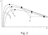
- Fig. 2 shows schematically the relationship between a percentage slip S on the abscissa and a driving force efficiency T on the ordinate during field work.
- the different curves K relate to different soil properties.
- the maximum of the curves K is in the range of a percentage slip S of 10% to 20% for normal soil properties.
- the respective maximum driving force efficiency O is approximately between 50% and 80% and is marked with a circle, while the diamond indicates an optimal slip for a maximum driving force coefficient D.
- the graph is only to be understood schematically.
- the agricultural vehicle 5 has a sensor 9 for detecting at least one of the existing soil properties, preferably that the sensor 9 detects a slope of the soil and/or a surface property of the soil, in particular a crumbling of the soil and/or a leveling of the soil.
- the sensor 9 is located in an area before soil cultivation by the attachment 3.
- the sensor 9 sit on the agricultural work machine 1.
- the sensor 9 can basically be a sensor 9 based on electromagnetic waves or acoustic waves.
- the sensor 9 can be a radar sensor or a lidar sensor or an optical sensor or an ultrasonic sensor.
- the sensor 9 can also be an inclination sensor that detects an inclination of the agricultural work machine 1 and preferably uses this to determine whether it is going uphill or downhill.
- the gradient as a soil property is particularly relevant in this case, since it can be detected with very little effort and at the same time it has a major influence on the control of the rear power lift 2.
- At least one of the soil properties is entered by a user 8 and/or is stored in a database DB.
- the at least one soil property can be stored in the database DB depending on the location. It is preferred that the at least one soil property in the database DB includes compaction.
- the ground property can be location-dependent. This is usually inherent in a sensor 9, but it is also preferred for a ground property that is entered or comes from a database DB.
- the ground property can, for example, include lane data that allow conclusions to be drawn about compaction in the lanes.
- the database DB can basically be part of the driver assistance system 6 or the data can be transmitted to the driver assistance system 6.
- location-dependent means that the soil properties change across a field and therefore still have a spatial resolution on the individual field.
- the agricultural vehicle 5 has a sensor 9 for detecting at least one existing tire property, and/or that at least one of the at least one tire property is entered by the user 8 and/or is stored in the database DB.
- the statements regarding the soil properties apply accordingly.
- the at least one tire property is a weight of the agricultural working machine 1, in particular an axle load and/or a axle ballasting, and/or a tire size and/or a tire rolling radius and/or a tire pressure.
- the tire properties can affect one or more tires. Overall, the slip depends on the ground, the weight on the tire, tire materials, and the like. These properties can therefore be taken into account to determine the target slip P.
- the driver assistance system 6 on the rear power lift 2 regulates a lifting gear position of the upper link 10 and/or one or more of the lower links 11 and/or a lifting gear force of one or more of the lower links 11 and/or a length of the upper link 10 and/or one or more of the lower links 11 and/or a lifting strut and/or an upper link force 10 as machine parameters.
- the driver assistance system 6 is defined broadly here. It can also have a rear force controller, which as such can be an independent module and which can be integrated in Fig. 1 represented by the second block R.
- the driver assistance system 6 determines the target slip P in order to achieve a maximum traction efficiency or a maximum traction coefficient or with regard to an optimized combination of traction efficiency and traction coefficient.
- the optimization with regard to the driving force efficiency and the driving force accessory is here and preferably dependent on a user specification.
- This user specification can be a target specification.
- the target specification can be a minimization of consumption or a maximization of a speed of carrying out the work process and/or a minimization of the costs of the process and/or a maximization of the work quality.
- the user 8 can set the weighting of the target specifications visually on the agricultural work machine 1.
- the driver assistance system 6 on the basis of the at least one existing soil property and the at least one existing tire property, temporarily controls the rear power lift 2 by means of a position control without slip control and/or a traction control without slip control and/or a mixed control of position control and traction control without slip control and preferably determines an optimized mixing factor of the mixed control for this purpose.
- the driver assistance system 6 can determine the optimized mixing factor for periods in which the target slip P is not reached and the slip control therefore does not take effect.
- driver assistance system 6 can therefore fall back on known controls. In particular, it can be provided that the driver assistance system 6 detects a lack of information on the ground properties and tire properties and deduces from this that an optimized target slip P cannot be determined with sufficient certainty.
- the driver assistance system 6 determines an optimized setting of a mixing factor of a mixed control of position control and traction control on the basis of the at least one existing ground property and the at least one existing tire property and/or the target slip and controls the rear power lift 2 based thereon.
- the position control or the traction control or in particular their mixture can also be optimized by the driver assistance system 6. This can be done to achieve a user specification.
- the user 8 can thus, for example, make the aforementioned target specifications or set a desired working depth 7 and the driver assistance system 6 takes over the control of the rear power lift 2.
- the driver assistance system 6 can then optimize the slip in terms of efficiency as standard, provided there is still room for maneuver.
- the driver assistance system 6 determines the mixing factor and preferably the target slip P to achieve a specification, in particular a user specification.
- the specification can in particular be a specified working depth 7 or a specified driving speed or a specified tractive force.
- a preferred procedure is that the user 8 specifies a working depth 7 and the tractive force and preferably a driving speed of the tractor-trailer combination 5 follow from the target slip P, since the agricultural work machine usually works at or close to full load when working the soil.
- driver assistance system 6 varies the settings of the rear power lift 2 in a map routine for given soil properties and tire properties in order to take into account dependencies between the soil properties and tire properties. and the slip, in particular in the form of a characteristic map, and then to determine the target slip P based on this.
- the map routine can run over several work processes and thus lead to optimization step by step or can be carried out at the beginning of each work process if necessary.
- Characteristic maps are equations or combinations of equations and/or inequalities or otherwise depicted dependencies between settings of machine parameters, measurement data, influencing factors and the like.
- the agricultural attachment 3 has a sensor 9 for determining an absolute working depth 7 for the working depth control.
- the sensor measures an absolute working depth.
- absolute does not necessarily mean a highly precise measurement, but rather a general measurement relative to the ground. In principle, it is conceivable that the measurement is carried out relative to a component whose height relative to the ground is known, but the absolute working depth is preferably measured directly relative to the ground.
- the sensor can be part of a sensor arrangement.
- the sensor arrangement can have at least one sensor holder, wherein the sensor is reversibly mounted at a mounting position on different attachments by means of the at least one sensor holder.
- the sensor is mounted at the mounting position using the sensor holder in such a way that the assembly is non-destructive and reversible. In particular, it is not carried out as part of the manufacture of the attachment, but is preferably carried out on site in the field with simple tools or without any tools at all.
- the sensor can therefore be used with various attachments and is therefore modular.
- An advantageous application of this modular sensor technology also concerns the measurement of the working depth on an attachment that does not have its own electronics.
- the sensor arrangement can therefore be self-sufficient. from the attachment.
- the sensor does not communicate with the attachment.
- the sensor is integrated into the electronics of the attachment or communicates with it. Even with attachments with electronics, it can be provided that the sensor does not communicate directly with the attachment. It is preferred that the sensor arrangement can be used with attachments with and without electronics. Overall, it can even be provided that the determination of the working depth is completely independent of the agricultural attachment.
- the sensor holder can be mounted separately from the sensor on the different attachments.
- the sensor can then be mounted reversibly on the sensor holder.
- the sensor holder is a relatively inexpensive mass-produced component, while the sensor itself is relatively expensive. The proposed method enables the expensive sensor to be reused.
- the sensor bracket may remain on the attachment. This allows the sensor bracket to be mounted in a stable and more complex manner, while mounting the sensor on the sensor bracket itself is preferably relatively simple. This also allows the same mounting position to be reused when the sensor is reattached.
- a reference height can be stored that indicates the working height when the distance between the sensor and the ground is known. The working height can then be calculated from the difference.
- the driver assistance system 6 further controls or regulates machine parameters of the attachment 3 depending on the target slip P and/or determines the target slip P depending on the machine parameters, preferably that the driver assistance system 6 controls or regulates a cutting width and/or a working depth 7 of a plow 4 depending on the target slip P.
- the driver assistance system 6 continues to determine the target slip P depending on a total weight of the agricultural combination 5 and an inclination of the ground and/or the agricultural combination 5.
- the agricultural combination 5 can have an inclination sensor for Determination of the inclination of the agricultural vehicle 5.
- the inclination of the ground can be taken from a database DB.
- the combined weight of the agricultural work machine 1 and the agricultural attachment 3 largely determines the behavior of the vehicle 5 on the slope.
- the driver assistance system 6 determines the weight of the agricultural vehicle combination 5 from an actual slip, in particular by successively adjusting the target slip. If the driver assistance system 6 sets a target slip P on a slope, the attachment is raised to a specific working depth 7 by the downstream control. Conclusions about the weight can be drawn from this. Additionally or alternatively, the driver assistance system 6 can use another actual value, in particular an actual position and/or an actual tractive force and/or an actual working depth, to determine the weight. The weight does not have to be determined as such; it is sufficient to adjust the target slip P depending on a weight-dependent value determined in this way or on the basis of a calculation rule that indirectly takes the weight into account. Preferably, the target slip is adjusted depending on the weight on a slope.
- the weight can also be entered by the user.
- an agricultural combination 5 wherein the agricultural combination 5 has an agricultural work machine 1 and an agricultural attachment 3, wherein the agricultural attachment 3 is connected to the agricultural work machine 1 via a rear power lift 2 of the agricultural work machine 1, wherein the agricultural work machine 1 has a driver assistance system 6 which regulates machine parameters of the rear power lift 2, wherein the driver assistance system 6 regulates the machine parameters of the rear power lift 2 by means of a position control and/or a traction control, on which a slip control is superimposed.
- the driver assistance system 6 determines a target slip P for the slip control that is optimized with regard to the position control and/or traction control and controls the rear power lift 2 to the optimized target slip P.
Landscapes
- Life Sciences & Earth Sciences (AREA)
- Engineering & Computer Science (AREA)
- Mechanical Engineering (AREA)
- Soil Sciences (AREA)
- Environmental Sciences (AREA)
- Lifting Devices For Agricultural Implements (AREA)
- Management, Administration, Business Operations System, And Electronic Commerce (AREA)
Claims (13)
- Procédé de réglage d'un relevage arrière (2) d'une machine agricole (1) dans un attelage agricole (5), où l'attelage agricole (5) comprend une machine agricole (1) et un outil agricole attelé (3), l'outil agricole attelé (3) étant relié à la machine agricole (1) par un relevage arrière (2) de la machine agricole (1),la machine agricole (1) présentant un système d'assistance au conducteur (6) qui règle des paramètres machine du relevage arrière (2),le système d'assistance au conducteur (6) réglant les paramètres machine du relevage arrière (2) au moyen d'un réglage de position et/ou d'un réglage de force de traction et/ou d'un réglage de profondeur de travail auquel est superposé un réglage de patinage,
caractérisé en ce quele système d'assistance au conducteur (6) détermine, en fonction d'au moins une propriété de sol disponible et d'au moins une caractéristique de pneu disponible, un patinage de consigne (P) pour le réglage de patinage, qui est optimisé en ce qui concerne le réglage de position et/ou le réglage de force de traction et/ou le réglage de profondeur de travail, et règle le relevage arrière (2) au patinage de consigne (P) optimisé. - Procédé selon la revendication 1, caractérisé en ce que l'attelage agricole (5) présente un capteur (9) destiné à la détection d'au moins une des propriétés de sol disponibles, de préférence en ce que le capteur (9) détecte une pente du sol et/ou une propriété de surface du sol, en particulier un émiettement du sol et/ou un nivellement du sol.
- Procédé selon la revendication 1 ou 2, caractérisé en ce qu'u moins une des propriétés du sol est saisie par un utilisateur (8) et/ou est enregistrée dans une base de données (DB), de préférence en ce que la propriété du sol, au nombre d'au moins une, est enregistrée dans la base de données (DB) en fonction du lieu, et en outre de préférence en ce que la propriété du sol, au nombre d'au moins une, de la base de données (DB) comprend un compactage.
- Procédé selon une des revendications précédentes, caractérisé en ce que l'attelage agricole (5) présente un capteur (9) destiné à la détection d'au moins une caractéristique de pneu disponible, et/ou en ce qu'au moins une des caractéristiques de pneu, au nombre d'au moins une, est saisie par l'utilisateur (8) et/ou est enregistrée dans la base de données (DB), de préférence en ce que la caractéristique de pneu, au nombre d'au moins une, comprend un poids de la machine agricole (1), en particulier une charge d'essieu et/ou un lestage d'essieu et/ou une dimension de pneu et/ou un rayon de roulement du pneu et/ou une pression de pneu.
- Procédé selon une des revendications précédentes, caractérisé en ce que le système d'assistance au conducteur (6) règle sur le relevage arrière (2), en tant que paramètre machine, une position du mécanisme de relevage du bras supérieur (10) et/ou d'un ou des bras inférieurs (11) et/ou une force de mécanisme de relevage d'un ou des bras inférieurs (11) et/ou une longueur du bras supérieur (10) et/ou d'un ou des bras inférieurs (11) et/ou d'une chandelle de relevage et/ou une force de bras supérieur (10).
- Procédé selon une des revendications précédentes, caractérisé en ce que le système d'assistance au conducteur (6) détermine le patinage de consigne (P) en vue d'atteindre une efficacité maximale de force motrice ou un coefficient maximal de force motrice, ou par rapport à une combinaison optimisée d'efficacité de force motrice et de coefficient de force motrice.
- Procédé selon une des revendications précédentes, caractérisé en ce que le système d'assistance au conducteur (6), sur la base de la propriété de sol disponible, au nombre d'au moins une, et de la caractéristique de pneu disponible, au nombre d'au moins une, règle temporairement le relevage arrière (2) au moyen d'un réglage de position sans réglage de patinage et/ou d'un réglage de force de traction sans réglage de patinage et/ou d'un réglage mixte de réglage de position et de réglage de force de traction sans réglage de patinage, et détermine de préférence à cet effet un facteur de mélange optimisé du réglage mixte.
- Procédé selon une des revendications précédentes, caractérisé en ce que le système d'assistance au conducteur (6), sur la base de la propriété de sol disponible, au nombre d'au moins une, et de la caractéristique de pneu disponible, au nombre d'au moins une, et/ou du patinage de consigne, détermine de manière optimisée un réglage d'un facteur de mélange d'un réglage mixte de réglage de position et de réglage de force de traction et règle le relevage arrière (2) sur cette base, de préférence en ce que le système d'assistance au conducteur (6) détermine le facteur de mélange et de préférence le patinage de consigne (P) en vue d'atteindre une consigne, notamment une consigne d'utilisateur, et en outre de préférence en ce que la consigne est une profondeur de travail (7) prédéfinie ou un vitesse de déplacement prédéfinie ou une force de traction prédéfinie.
- Procédé selon une des revendications précédentes, caractérisé en ce que le système d'assistance au conducteur (6), dans une routine de diagramme caractéristique avec des propriétés de sol et des caractéristiques de pneu données, fait varier des réglages du relevage arrière (2) aux fins de déterminer des interdépendances entre les propriétés du sol et les caractéristiques de pneu et le patinage, notamment sous la forme d'un diagramme caractéristique, et de déterminer ensuite le patinage de consigne (P) sur cette base.
- Procédé selon une des revendications précédentes, caractérisé en ce que l'outil agricole attelé (3) présente un capteur (9) destiné à déterminer une profondeur de travail (7) absolue pour le réglage de la profondeur de travail.
- Procédé selon une des revendications précédentes, caractérisé en ce que le système d'assistance au conducteur (6) contrôle ou règle en outre des paramètres machine de l'outil attelé (3), en fonction du patinage de consigne (P), et/ou détermine le patinage de consigne (P) en fonction des paramètres machine, de préférence en ce que le système d'assistance au conducteur (6) contrôle ou règle une largeur de coupe et/ou une profondeur de travail (7) d'une charrue (4), en fonction du patinage de consigne (P).
- Procédé selon une des revendications précédentes, caractérisé en ce que le système d'assistance au conducteur (6) détermine le patinage de consigne (P) en outre en fonction d'un poids total de l'attelage agricole (5) et d'une inclinaison du sol et/ou de l'attelage agricole (5).
- Attelage agricole, où l'attelage agricole (5) comprend une machine agricole (1) et un outil agricole attelé (3), l'outil agricole attelé (3) étant relié à la machine agricole (1) par un relevage arrière (2) de la machine agricole (1),la machine agricole (1) présentant un système d'assistance au conducteur (6) qui est conçu pour régler des paramètres machine du relevage arrière (2),le système d'assistance au conducteur (6) étant conçu pour régler les paramètres machine du relevage arrière (2) au moyen d'un réglage de position et/ou d'un réglage de force de traction auquel ou auxquels est superposé un réglage de patinage,
caractérisé en ce quele système d'assistance au conducteur (6) est en outre conçu pour déterminer, en fonction d'au moins une propriété de sol disponible et d'au moins une caractéristique de pneu disponible, un patinage de consigne (P) pour le réglage de patinage qui est optimisé en ce qui concerne le réglage de position et/ou le réglage de force de traction, et pour régler le relevage arrière (2) sur le patinage de consigne (P) optimisé.
Applications Claiming Priority (1)
| Application Number | Priority Date | Filing Date | Title |
|---|---|---|---|
| DE102021120813.0A DE102021120813A1 (de) | 2021-08-10 | 2021-08-10 | Verfahren zur Regelung eines Heckkrafthebers einer landwirtschaftlichen Arbeitsmaschine |
Publications (2)
| Publication Number | Publication Date |
|---|---|
| EP4133924A1 EP4133924A1 (fr) | 2023-02-15 |
| EP4133924B1 true EP4133924B1 (fr) | 2024-12-18 |
Family
ID=81580863
Family Applications (1)
| Application Number | Title | Priority Date | Filing Date |
|---|---|---|---|
| EP22168327.9A Active EP4133924B1 (fr) | 2021-08-10 | 2022-04-14 | Procédé de réglage d'un relevage arrière d'une machine agricole |
Country Status (3)
| Country | Link |
|---|---|
| US (1) | US12477967B2 (fr) |
| EP (1) | EP4133924B1 (fr) |
| DE (1) | DE102021120813A1 (fr) |
Families Citing this family (1)
| Publication number | Priority date | Publication date | Assignee | Title |
|---|---|---|---|---|
| DE102020102330A1 (de) * | 2020-01-30 | 2021-08-05 | CLAAS Tractor S.A.S | Zugmaschine |
Family Cites Families (12)
| Publication number | Priority date | Publication date | Assignee | Title |
|---|---|---|---|---|
| US6041582A (en) * | 1998-02-20 | 2000-03-28 | Case Corporation | System for recording soil conditions |
| JP5375371B2 (ja) * | 2009-06-30 | 2013-12-25 | 株式会社アドヴィックス | 車両運動制御装置 |
| DE102011085040A1 (de) * | 2011-10-21 | 2013-04-25 | Deere & Company | Landwirtschaftliches Fahrzeug |
| JP6201209B2 (ja) * | 2013-09-12 | 2017-09-27 | 日立オートモティブシステムズ株式会社 | 駆動力制御装置及び駆動力制御方法 |
| GB201420529D0 (en) | 2014-11-19 | 2014-12-31 | Agco Int Gmbh | Vehicle wheel slippage control |
| US9650053B2 (en) * | 2014-12-03 | 2017-05-16 | The Goodyear Tire & Rubber Company | Slip ratio point optimization system and method for vehicle control |
| US10053100B2 (en) * | 2015-10-09 | 2018-08-21 | Cnh Industrial America Llc | Slip control system for an off-road vehicle |
| DE102016118297A1 (de) | 2016-09-28 | 2018-03-29 | Claas Tractor Sas | Verfahren und System zur Bestimmung eines Betriebspunktes |
| DE102016226287A1 (de) * | 2016-12-29 | 2018-07-05 | Robert Bosch Gmbh | Vorrichtung und Verfahren zur Regelung des Fahrbetriebs eines Fahrzeugs mit einem Anbaugerät oder Anhänger |
| US10444176B2 (en) * | 2017-02-17 | 2019-10-15 | Deere & Company | Sensing system for measuring soil properties in real time |
| CN108717261B (zh) * | 2018-03-12 | 2021-02-12 | 江苏大学 | 一种用于犁耕机组最优滑转率识别装置及其控制方法 |
| US10669697B2 (en) * | 2018-04-02 | 2020-06-02 | Caterpillar Inc. | Performance monitor for a machine |
-
2021
- 2021-08-10 DE DE102021120813.0A patent/DE102021120813A1/de active Pending
-
2022
- 2022-04-14 EP EP22168327.9A patent/EP4133924B1/fr active Active
- 2022-08-04 US US17/880,900 patent/US12477967B2/en active Active
Also Published As
| Publication number | Publication date |
|---|---|
| US20230047061A1 (en) | 2023-02-16 |
| US12477967B2 (en) | 2025-11-25 |
| DE102021120813A1 (de) | 2023-02-16 |
| EP4133924A1 (fr) | 2023-02-15 |
Similar Documents
| Publication | Publication Date | Title |
|---|---|---|
| EP3050416B1 (fr) | Appareil de travail du sol | |
| EP3243368B2 (fr) | Combinaison d'appareil de véhicule de traction ayant un système d'assistance au conducteur | |
| EP3858644B1 (fr) | Tracteur | |
| DE102019122116A1 (de) | Landwirtschaftliches Gespann mit einer Zugmaschine und einem Pflug | |
| EP1273216B1 (fr) | Outil pour le travail du sol | |
| DE102014206234B4 (de) | Fahrzeug mit Bodenbearbeitungsgerät und Antriebsschlupfregelung | |
| EP4133922A1 (fr) | Procédé de détermination des hauteurs de travail indépendantes du type d'accouplement d'une pluralité d'accessoires agricoles | |
| EP3311641B1 (fr) | Dispositif de commande pour un engin moteur, engin moteur doté d'un dispositif de commande et procédé de commande d'un engin moteur | |
| WO2016192973A1 (fr) | Dispositif de commande pour un tracteur, tracteur présentant un dispositif de commande et procédé pour un dispositif de commande | |
| DE3235818A1 (de) | Einrichtung zur steuerung der arbeitstiefe eines bodenbearbeitungsgeraetes | |
| EP3300557B1 (fr) | Dispositif et procédé de controle du fonctionnement d'un appareil isolé hydraulique d'un véhicule | |
| EP0786200A2 (fr) | Dispositif de régulation de position d'une unité de travail d'une machine agricole | |
| EP3721691A1 (fr) | Procédé de commande du fonctionnement d'un accessoire | |
| DE10140383A1 (de) | Steuerung oder Regelung der Lage eines an einem Schlepper angebauten Anbaugerätes | |
| EP4133924A1 (fr) | Procédé de réglage d'un relevage arrière d'une machine agricole | |
| DE102007039105B4 (de) | Hubwerk und Verfahren zum Steuern eines Hubwerkes | |
| EP3533307B1 (fr) | Procédé de commande d'un bras supérieur hydraulique d'un attelage trois points | |
| EP3424287A1 (fr) | Dispositif et procédé de réglage du fonctionnement d'un outil porté hydraulique pour un véhicule | |
| EP4193819A1 (fr) | Machine agricole | |
| EP4133925B1 (fr) | Procédé de fonctionnement d'une combinaison véhicule-outil agricole | |
| EP4327638A1 (fr) | Procédé de fonctionnement d'un système de travail agricole | |
| DE3513064C2 (fr) | ||
| EP4133927B1 (fr) | Procédé d'optimisation du réglage des paramètres machine d'un attelage agricole | |
| EP3701779B1 (fr) | Machine agricole et procédé de fonctionnement d'une machine agricole | |
| DE102011076296B4 (de) | Verfahren zur Steuerung mindestens eines Hubwerks eines landwirtschaftlichen oder kommunalen Nutzfahrzeuges, sowie Nutzfahrzeug |
Legal Events
| Date | Code | Title | Description |
|---|---|---|---|
| PUAI | Public reference made under article 153(3) epc to a published international application that has entered the european phase |
Free format text: ORIGINAL CODE: 0009012 |
|
| STAA | Information on the status of an ep patent application or granted ep patent |
Free format text: STATUS: THE APPLICATION HAS BEEN PUBLISHED |
|
| AK | Designated contracting states |
Kind code of ref document: A1 Designated state(s): AL AT BE BG CH CY CZ DE DK EE ES FI FR GB GR HR HU IE IS IT LI LT LU LV MC MK MT NL NO PL PT RO RS SE SI SK SM TR |
|
| P01 | Opt-out of the competence of the unified patent court (upc) registered |
Effective date: 20230516 |
|
| STAA | Information on the status of an ep patent application or granted ep patent |
Free format text: STATUS: REQUEST FOR EXAMINATION WAS MADE |
|
| 17P | Request for examination filed |
Effective date: 20230816 |
|
| RBV | Designated contracting states (corrected) |
Designated state(s): AL AT BE BG CH CY CZ DE DK EE ES FI FR GB GR HR HU IE IS IT LI LT LU LV MC MK MT NL NO PL PT RO RS SE SI SK SM TR |
|
| GRAP | Despatch of communication of intention to grant a patent |
Free format text: ORIGINAL CODE: EPIDOSNIGR1 |
|
| STAA | Information on the status of an ep patent application or granted ep patent |
Free format text: STATUS: GRANT OF PATENT IS INTENDED |
|
| INTG | Intention to grant announced |
Effective date: 20240715 |
|
| GRAS | Grant fee paid |
Free format text: ORIGINAL CODE: EPIDOSNIGR3 |
|
| GRAA | (expected) grant |
Free format text: ORIGINAL CODE: 0009210 |
|
| STAA | Information on the status of an ep patent application or granted ep patent |
Free format text: STATUS: THE PATENT HAS BEEN GRANTED |
|
| AK | Designated contracting states |
Kind code of ref document: B1 Designated state(s): AL AT BE BG CH CY CZ DE DK EE ES FI FR GB GR HR HU IE IS IT LI LT LU LV MC MK MT NL NO PL PT RO RS SE SI SK SM TR |
|
| REG | Reference to a national code |
Ref country code: CH Ref legal event code: EP |
|
| REG | Reference to a national code |
Ref country code: DE Ref legal event code: R096 Ref document number: 502022002407 Country of ref document: DE |
|
| REG | Reference to a national code |
Ref country code: IE Ref legal event code: FG4D Free format text: LANGUAGE OF EP DOCUMENT: GERMAN |
|
| REG | Reference to a national code |
Ref country code: LT Ref legal event code: MG9D |
|
| PG25 | Lapsed in a contracting state [announced via postgrant information from national office to epo] |
Ref country code: HR Free format text: LAPSE BECAUSE OF FAILURE TO SUBMIT A TRANSLATION OF THE DESCRIPTION OR TO PAY THE FEE WITHIN THE PRESCRIBED TIME-LIMIT Effective date: 20241218 |
|
| PG25 | Lapsed in a contracting state [announced via postgrant information from national office to epo] |
Ref country code: FI Free format text: LAPSE BECAUSE OF FAILURE TO SUBMIT A TRANSLATION OF THE DESCRIPTION OR TO PAY THE FEE WITHIN THE PRESCRIBED TIME-LIMIT Effective date: 20241218 |
|
| PG25 | Lapsed in a contracting state [announced via postgrant information from national office to epo] |
Ref country code: BG Free format text: LAPSE BECAUSE OF FAILURE TO SUBMIT A TRANSLATION OF THE DESCRIPTION OR TO PAY THE FEE WITHIN THE PRESCRIBED TIME-LIMIT Effective date: 20241218 |
|
| PG25 | Lapsed in a contracting state [announced via postgrant information from national office to epo] |
Ref country code: NO Free format text: LAPSE BECAUSE OF FAILURE TO SUBMIT A TRANSLATION OF THE DESCRIPTION OR TO PAY THE FEE WITHIN THE PRESCRIBED TIME-LIMIT Effective date: 20250318 |
|
| REG | Reference to a national code |
Ref country code: NL Ref legal event code: MP Effective date: 20241218 |
|
| PG25 | Lapsed in a contracting state [announced via postgrant information from national office to epo] |
Ref country code: GR Free format text: LAPSE BECAUSE OF FAILURE TO SUBMIT A TRANSLATION OF THE DESCRIPTION OR TO PAY THE FEE WITHIN THE PRESCRIBED TIME-LIMIT Effective date: 20250319 Ref country code: LV Free format text: LAPSE BECAUSE OF FAILURE TO SUBMIT A TRANSLATION OF THE DESCRIPTION OR TO PAY THE FEE WITHIN THE PRESCRIBED TIME-LIMIT Effective date: 20241218 |
|
| PG25 | Lapsed in a contracting state [announced via postgrant information from national office to epo] |
Ref country code: RS Free format text: LAPSE BECAUSE OF FAILURE TO SUBMIT A TRANSLATION OF THE DESCRIPTION OR TO PAY THE FEE WITHIN THE PRESCRIBED TIME-LIMIT Effective date: 20250318 |
|
| PG25 | Lapsed in a contracting state [announced via postgrant information from national office to epo] |
Ref country code: NL Free format text: LAPSE BECAUSE OF FAILURE TO SUBMIT A TRANSLATION OF THE DESCRIPTION OR TO PAY THE FEE WITHIN THE PRESCRIBED TIME-LIMIT Effective date: 20241218 |
|
| PG25 | Lapsed in a contracting state [announced via postgrant information from national office to epo] |
Ref country code: SM Free format text: LAPSE BECAUSE OF FAILURE TO SUBMIT A TRANSLATION OF THE DESCRIPTION OR TO PAY THE FEE WITHIN THE PRESCRIBED TIME-LIMIT Effective date: 20241218 |
|
| PG25 | Lapsed in a contracting state [announced via postgrant information from national office to epo] |
Ref country code: PL Free format text: LAPSE BECAUSE OF FAILURE TO SUBMIT A TRANSLATION OF THE DESCRIPTION OR TO PAY THE FEE WITHIN THE PRESCRIBED TIME-LIMIT Effective date: 20241218 |
|
| PGFP | Annual fee paid to national office [announced via postgrant information from national office to epo] |
Ref country code: DE Payment date: 20250422 Year of fee payment: 4 |
|
| PG25 | Lapsed in a contracting state [announced via postgrant information from national office to epo] |
Ref country code: ES Free format text: LAPSE BECAUSE OF FAILURE TO SUBMIT A TRANSLATION OF THE DESCRIPTION OR TO PAY THE FEE WITHIN THE PRESCRIBED TIME-LIMIT Effective date: 20241218 |
|
| PG25 | Lapsed in a contracting state [announced via postgrant information from national office to epo] |
Ref country code: IS Free format text: LAPSE BECAUSE OF FAILURE TO SUBMIT A TRANSLATION OF THE DESCRIPTION OR TO PAY THE FEE WITHIN THE PRESCRIBED TIME-LIMIT Effective date: 20250418 |
|
| PG25 | Lapsed in a contracting state [announced via postgrant information from national office to epo] |
Ref country code: PT Free format text: LAPSE BECAUSE OF FAILURE TO SUBMIT A TRANSLATION OF THE DESCRIPTION OR TO PAY THE FEE WITHIN THE PRESCRIBED TIME-LIMIT Effective date: 20250421 |
|
| PG25 | Lapsed in a contracting state [announced via postgrant information from national office to epo] |
Ref country code: EE Free format text: LAPSE BECAUSE OF FAILURE TO SUBMIT A TRANSLATION OF THE DESCRIPTION OR TO PAY THE FEE WITHIN THE PRESCRIBED TIME-LIMIT Effective date: 20241218 |
|
| PGFP | Annual fee paid to national office [announced via postgrant information from national office to epo] |
Ref country code: FR Payment date: 20250425 Year of fee payment: 4 |
|
| PG25 | Lapsed in a contracting state [announced via postgrant information from national office to epo] |
Ref country code: RO Free format text: LAPSE BECAUSE OF FAILURE TO SUBMIT A TRANSLATION OF THE DESCRIPTION OR TO PAY THE FEE WITHIN THE PRESCRIBED TIME-LIMIT Effective date: 20241218 |
|
| PGFP | Annual fee paid to national office [announced via postgrant information from national office to epo] |
Ref country code: AT Payment date: 20250721 Year of fee payment: 4 |
|
| PG25 | Lapsed in a contracting state [announced via postgrant information from national office to epo] |
Ref country code: SK Free format text: LAPSE BECAUSE OF FAILURE TO SUBMIT A TRANSLATION OF THE DESCRIPTION OR TO PAY THE FEE WITHIN THE PRESCRIBED TIME-LIMIT Effective date: 20241218 |
|
| PG25 | Lapsed in a contracting state [announced via postgrant information from national office to epo] |
Ref country code: CZ Free format text: LAPSE BECAUSE OF FAILURE TO SUBMIT A TRANSLATION OF THE DESCRIPTION OR TO PAY THE FEE WITHIN THE PRESCRIBED TIME-LIMIT Effective date: 20241218 |
|
| PG25 | Lapsed in a contracting state [announced via postgrant information from national office to epo] |
Ref country code: IT Free format text: LAPSE BECAUSE OF FAILURE TO SUBMIT A TRANSLATION OF THE DESCRIPTION OR TO PAY THE FEE WITHIN THE PRESCRIBED TIME-LIMIT Effective date: 20241218 |
|
| PG25 | Lapsed in a contracting state [announced via postgrant information from national office to epo] |
Ref country code: SE Free format text: LAPSE BECAUSE OF FAILURE TO SUBMIT A TRANSLATION OF THE DESCRIPTION OR TO PAY THE FEE WITHIN THE PRESCRIBED TIME-LIMIT Effective date: 20241218 |
|
| REG | Reference to a national code |
Ref country code: DE Ref legal event code: R097 Ref document number: 502022002407 Country of ref document: DE |
|
| PG25 | Lapsed in a contracting state [announced via postgrant information from national office to epo] |
Ref country code: DK Free format text: LAPSE BECAUSE OF FAILURE TO SUBMIT A TRANSLATION OF THE DESCRIPTION OR TO PAY THE FEE WITHIN THE PRESCRIBED TIME-LIMIT Effective date: 20241218 |
|
| PLBE | No opposition filed within time limit |
Free format text: ORIGINAL CODE: 0009261 |
|
| STAA | Information on the status of an ep patent application or granted ep patent |
Free format text: STATUS: NO OPPOSITION FILED WITHIN TIME LIMIT |
|
| REG | Reference to a national code |
Ref country code: CH Ref legal event code: L10 Free format text: ST27 STATUS EVENT CODE: U-0-0-L10-L00 (AS PROVIDED BY THE NATIONAL OFFICE) Effective date: 20251029 |
|
| REG | Reference to a national code |
Ref country code: CH Ref legal event code: H13 Free format text: ST27 STATUS EVENT CODE: U-0-0-H10-H13 (AS PROVIDED BY THE NATIONAL OFFICE) Effective date: 20251125 |
|
| 26N | No opposition filed |
Effective date: 20250919 |
|
| PG25 | Lapsed in a contracting state [announced via postgrant information from national office to epo] |
Ref country code: LU Free format text: LAPSE BECAUSE OF NON-PAYMENT OF DUE FEES Effective date: 20250414 |
|
| PG25 | Lapsed in a contracting state [announced via postgrant information from national office to epo] |
Ref country code: MC Free format text: LAPSE BECAUSE OF FAILURE TO SUBMIT A TRANSLATION OF THE DESCRIPTION OR TO PAY THE FEE WITHIN THE PRESCRIBED TIME-LIMIT Effective date: 20241218 |
|
| REG | Reference to a national code |
Ref country code: BE Ref legal event code: MM Effective date: 20250430 |
|
| PG25 | Lapsed in a contracting state [announced via postgrant information from national office to epo] |
Ref country code: BE Free format text: LAPSE BECAUSE OF NON-PAYMENT OF DUE FEES Effective date: 20250430 |
|
| PG25 | Lapsed in a contracting state [announced via postgrant information from national office to epo] |
Ref country code: CH Free format text: LAPSE BECAUSE OF NON-PAYMENT OF DUE FEES Effective date: 20250430 |
|
| PG25 | Lapsed in a contracting state [announced via postgrant information from national office to epo] |
Ref country code: IE Free format text: LAPSE BECAUSE OF NON-PAYMENT OF DUE FEES Effective date: 20250414 |