EP4133932B1 - Méthode de commande d'une remorque accompagnant une machine de récolte - Google Patents
Méthode de commande d'une remorque accompagnant une machine de récolte Download PDFInfo
- Publication number
- EP4133932B1 EP4133932B1 EP22188041.2A EP22188041A EP4133932B1 EP 4133932 B1 EP4133932 B1 EP 4133932B1 EP 22188041 A EP22188041 A EP 22188041A EP 4133932 B1 EP4133932 B1 EP 4133932B1
- Authority
- EP
- European Patent Office
- Prior art keywords
- harvesting machine
- speed
- control signal
- trailer
- tractor
- Prior art date
- Legal status (The legal status is an assumption and is not a legal conclusion. Google has not performed a legal analysis and makes no representation as to the accuracy of the status listed.)
- Active
Links
Images


Classifications
-
- A—HUMAN NECESSITIES
- A01—AGRICULTURE; FORESTRY; ANIMAL HUSBANDRY; HUNTING; TRAPPING; FISHING
- A01D—HARVESTING; MOWING
- A01D43/00—Mowers combined with apparatus performing additional operations while mowing
- A01D43/08—Mowers combined with apparatus performing additional operations while mowing with means for cutting up the mown crop, e.g. forage harvesters
- A01D43/086—Mowers combined with apparatus performing additional operations while mowing with means for cutting up the mown crop, e.g. forage harvesters and means for collecting, gathering or loading mown material
- A01D43/087—Mowers combined with apparatus performing additional operations while mowing with means for cutting up the mown crop, e.g. forage harvesters and means for collecting, gathering or loading mown material with controllable discharge spout
Definitions
- the present invention relates to a method for controlling a vehicle team accompanying a harvesting machine, according to the preamble of claim 1, and to a vehicle combination according to claim 14.
- a loading device often a discharge spout, is used to load the harvested crops, which may be corn or grass, for example.
- the accompanying vehicle which may be part of a tractor-trailer combination, drives either next to the harvesting machine or - for example when chopping - behind it.
- the relative position of the accompanying vehicle to the harvesting machine is of key importance for trouble-free loading.
- the loading device is usually adjustable in order to unload harvested crops into different areas, it is not possible to compensate for random, unpredictable changes in the position of the accompanying vehicle.
- US 2012/0263560 A1 discloses a system for controlling a crop overload from a self-propelled agricultural harvesting machine into a loading container of a transport vehicle, wherein a control unit is operable to specify a relative position of the transport vehicle with respect to the harvesting machine suitable for overloading into the loading container.
- the publication EP 2 452 551 A2 discloses a control arrangement for controlling the transfer of agricultural crops from a harvesting machine to a Transport vehicle comprising a loading container, wherein a control device is operable to automatically control the position of the discharge end of a discharge device relative to the harvesting machine and/or the ejection direction of the discharge device and/or the position of the transport vehicle with the loading container relative to the harvesting machine.
- the object of the invention is to provide an alternative, in particular economically feasible, possibility for coordinating the movements of a harvesting machine and an accompanying team.
- a method for controlling a combination accompanying a harvesting machine, which combination comprises a tractor and a trailer pulled by it, onto which the harvesting machine at least temporarily loads crops by means of a loading device, wherein the harvesting machine sends a first control signal with a first transmitting device in order to influence a relative position of the trailer relative to the harvesting machine.
- the harvesting machine can in particular be a forage harvester or a combine harvester.
- the harvesting machine picks up crops, e.g. corn, grain or grass, and loads this onto the trailer, normally after further processing, e.g. by chopping.
- the loading itself takes place using a loading device on the harvester, which is usually used to direct and/or bundle the overloaded crop flow.
- the loading device can be a discharge spout or discharge arch.
- the trailer together with a tractor, is part of a team that accompanies the harvester. Normally, the team drives next to or behind the harvester and at least roughly parallel to it.
- the tractor which can also be referred to as a tractor, can be designed in different ways, but is always self-propelled, i.e. equipped with its own drive and designed to pull the trailer.
- the trailer normally does not have its own drive. It is designed to pick up the overloaded crop, so it has a corresponding loading space.
- the trailer can also be a loading wagon that is equipped with a pickup device or pick-up to pick up crops from the ground.
- the trailer can have a weighing device by means of which the weight of the harvested crop that has already been picked up can be determined.
- the harvested crop is loaded at least temporarily, ie it can either be continuous, i.e. without interruptions, or breaks can be provided, during which, for example, the harvested crop is temporarily stored in the harvesting machine.
- the harvester sends a first control signal using a first transmitting device in order to influence the relative position of the trailer relative to the harvester.
- the aim is to set the relative position as precisely as possible, although in practice this may not always be possible.
- the harvester normally moves on a designated first lane, while the trailer moves on a second lane that is also designated.
- the lanes mentioned are normally parallel to one another, with minor deviations, and can also be identical to one another, e.g. when chopping. In this respect, it is normally only intended to influence the relative position in relation to the designated lanes, i.e. in a "one-dimensional" way. It goes without saying that the relative position is closely related to the speeds of the harvester and the trailer or the difference between these speeds.
- the term “transmit” generally refers to both wireless and wired transmissions
- the first control signal is usually transmitted wirelessly, ie the first transmitting device is designed for wireless transmission. It can be an analogue signal, but is usually a digital signal.
- the trailer receives the first control signal with a first receiving device and, depending on the first control signal, sends a second control signal with a second transmitting device, which contains speed information, whereby the tractor receives the second control signal with a second receiving device and then sets its actual speed in accordance with the speed information.
- the trailer has a first receiving device that is compatible with a first transmitting device of the harvesting machine and can thus receive the first control signal. These can thus communicate at least one-way via a first transmission path.
- Each transmitting device and receiving device mentioned here and below can be designed as a transmitting-receiving device, so that two-way communication is possible, although this is not necessary to implement the invention.
- the trailer can have a processing unit that processes the first control signal and, for example, decodes information contained therein.
- the same or a different processing unit can also be used to generate the second control signal, which is sent via the second transmitting device.
- the second transmitting device is also arranged on the trailer or is part of it.
- the second control signal contains speed information, one could also say information that relates to a speed.
- the second control signal is received by the tractor by means of a second receiving device.
- the second transmitting device and the second receiving device are thus compatible and can communicate at least one-way via a second transmission path. Since the tractor and the trailers are mechanically coupled to each other anyway for the transmission of traction, the second control signal can also be transmitted via a wire.
- the trailer and the tractor can in particular be connected via an ISOBUS, via which the second transmitting device sends the second control signal (digital) to the second receiving device. Wireless transmission is of course also possible.
- the tractor When the tractor receives the second control signal, it sets its actual speed according to the speed information. It goes without saying that the tractor can also have a processing unit that processes the second control signal and derives the target speed from it. If the speed information indicates that the tractor needs to change its actual speed (i.e. increase or decrease it), the actual speed is adjusted accordingly; otherwise the current actual speed is maintained. It should be noted that the accuracy of setting the actual speed depends, among other things, on the accuracy with which the tractor knows its actual speed, i.e. how precisely it can measure it.
- the speed of the tractor is not controlled directly via the first control signal sent by the harvester, but indirectly via the trailer using the second control signal.
- the method according to the invention has clear advantages. These are based in particular on the fact that controlling the functions of a tractor using a trailer (or another additional device) is already an established standard for many manufacturers, which also enables cross-manufacturer connections, particularly in the form of the so-called TIM (Tractor Implement Management).
- TIM Traffic Implement Management
- An existing infrastructure can thus be used for external control of the tractor, which would not be possible with direct control by the harvesting machine (at least not using the widely used TIM).
- external control of the tractor by the trailer is already provided, all that is required is a communication option between the harvesting machine and the trailer (via the first transmitting device and the first receiving device) and a connection between the first receiving device and the second transmitting device, possibly with intermediate signal processing, in order to generate the second control signal from the first control signal.
- the communication between the harvesting machine and the trailer can also be used for other purposes. If two-way communication is possible, data from a weighing device on the trailer can, for example, be transmitted to the harvesting machine, which in turn can be used by the harvesting machine to calibrate yield recording.
- control signal in this context is not to be interpreted as meaning that the tractor is controlled in the sense of steering.
- first or second control signal could also contain information about a steering angle
- the steering angle is normally set independently of the control signals mentioned.
- the tractor normally follows a predetermined (second) lane, compliance with which can be checked, for example, using GPS, optical sensors or the like.
- the speed information could, for example, be an instruction to increase or decrease the actual speed.
- a target speed is specified with the second control signal, whereby the tractor sets its actual speed according to the target speed.
- a target speed is specified with the second control signal, ie the target speed is either directly in the second control signal (e.g. in coded form) or can be derived from it.
- the tractor receives the second control signal, it sets its actual speed according to the target speed.
- a processing unit can also be present on the tractor side, which processes the second control signal and derives the target speed from it. If the specified target speed deviates from the current actual speed, the actual speed is adjusted accordingly. Otherwise, the current actual speed is maintained. In this embodiment, too, it is relevant with what accuracy the actual speed is available from the tractor. If the accuracy is insufficient, setting "according to the target speed" may not result in the specified target speed actually being reached.
- the target speed can only be derived indirectly from the first control signal, for example in such a way that the first control signal indicates a relative position that the trailer should reach, from which the target speed can be derived with the help of further information.
- the target speed is specified with the first control signal.
- the target speed can be contained in the first control signal, for example in digitally coded form.
- a typical operating mode provides for the loading wagon to travel at a constant relative position (next to or behind the harvester). If the harvester and the trailer are travelling straight ahead, their speeds must match. This means that the first control signal can be used to specify a target speed that matches the speed of the harvester. In certain situations, however, it is useful for the first control signal to at least temporarily specify a target speed of the harvester that differs from the harvester speed in order to change the relative position of the trailer. If the trailer is to be positioned further forward in relation to the harvester, a target speed can be selected that is greater than the harvester speed; if it is to be further positioned at the rear, a target speed can be selected that is lower than the harvester speed.
- the harvester speed can be determined, for example, via GPS or from the speed of an engine or other drive components of the harvester.
- the target speed can be calibrated (at least once, preferably repeatedly) so that it is changed by a calibration factor in order to compensate for a deviation of the actual speed from the target speed caused by slip.
- a calibration factor which is usually greater than 1.
- a target speed is transmitted that is greater than the harvester speed by the calibration factor. It is usually sufficient that the same calibration factor is used for all target speeds given to the tractor (at least until the next calibration). It should be noted that the drive wheels of the harvester generally also slip, which in some situations can be as large or even larger than the slip on the drive wheels of the tractor. The latter could be compensated for, for example, by a calibration factor that is less than 1. Since the slip changes depending on the soil conditions and in particular on the increasing load of the trailer over time, repeated calibration with corresponding adjustment of the calibration factor is usually necessary.
- Calibration is preferably carried out on the harvester side, so that the calibrated target speed is specified with the first control signal.
- the first control signal specifies the target speed already modified by the calibration factor.
- Calibration can possibly be carried out automatically, e.g. in such a way that the harvester repeatedly determines the relative position (e.g. by comparing GPS data) and checks whether this develops in accordance with the harvester speed and the transmitted target speed (e.g. remains constant).
- calibration can also be carried out by a driver of the harvester. The driver can, for example, visually check the relative position of the trailer and, if necessary, carry out the calibration manually.
- a slider could be used to change the calibration factor, with the driver changing the position of the slider until the relative position of the trailer no longer changes.
- the target speed is automatically adjusted depending on the curve radii and the harvester speed of the harvester.
- the unit on the inside of the curve (harvester or team) must travel slower than the unit on the outside of the curve (team or harvester).
- the ratio of the driving speeds should correspond to the ratio of the curve radii.
- the target speed can be adjusted based on this. If this is not the case, there are other options, some of which are discussed below.
- the curve radius of the trailer is automatically adjusted to adjust the target speed depending on the curve radius of the harvester. and the alignment of the loading device of the harvesting machine. For example, if the harvesting machine is making a right-hand bend and the loading device is aligned to the right, it can be assumed that the combination forms the unit on the inside of the bend, while it forms the unit on the outside of the bend if the loading device is aligned to the left. This means that the curve radius of the combination can be determined at least approximately, even if it is not otherwise known, and used to adjust the target speed. To determine the curve radius more precisely, other parameters can be used, such as a set front attachment width of the harvesting machine.
- a loading area within the trailer into which the crop is transferred is varied over time.
- the crop is transferred to different areas of the trailer in chronological order.
- the area in which the transfer is currently taking place is referred to as the loading area. It is understood that the loading area depends on the relative position and on the (current) arrangement of the transfer device in relation to the harvesting machine.
- the loading area by changing the relative position of the trailer by temporarily specifying a target speed that corresponds to an actual speed of the harvester that differs from the harvester speed. This means that there is no attempt to make the combination travel at the same speed as the harvester, but rather the intention is for the combination to travel faster or slower at times.
- the target speed (which may be calibrated) is specified accordingly. If the target speed is selected so that it corresponds to an actual speed that is greater than the harvester speed, the combination moves forward relative to the harvester and the loading area shifts to the rear within the trailer. If the target speed is selected so that it corresponds to an actual speed that is lower than the harvester speed, the trailer falls back compared to the harvester and the loading area shifts forward within the trailer.
- the loading area can be varied by changing the settings of the transfer device. This can be done, for example, by pivoting the transfer device and/or adjusting a discharge flap. It is usually necessary to also vary the settings of the transfer device, since changing the relative position only allows the loading area to be moved parallel to the direction of travel, not across it.
- the loading area can be varied automatically by an automatic transfer system on the harvesting machine.
- the corresponding automatic transfer system can use suitable sensors (e.g. one or more cameras) to determine the current distribution of the crop in the trailer and change the loading area in such a way that an overall even distribution is achieved.
- the automatic transfer system can in particular control the setting of the transfer device, but it could also (normally additionally) automatically change the relative position by specifying a suitable target speed for the tractor.
- the automatic transfer system can be partially implemented using software.
- the terms mentioned have been explained largely with reference to the method according to the invention and will not be explained again in this respect.
- the term "for the harvesting machine” means that the respective device is intended to be attached or integrated to or in the harvesting machine.
- the speed controller is coupled directly or indirectly (e.g. via a processing unit) to the second receiving device and, when installed, is connected to the drive of the tractor in such a way that it can set the actual speed via the drive as described.
- control arrangement correspond to those of the method according to the invention.
- the object is further achieved with a vehicle combination comprising a harvesting machine and a tractor-trailer combination with a trailer pulled by the tractor, according to claim 14.
- the harvesting machine is designed to transfer crops onto the trailer by means of a transfer device and has a first transmitting device which is designed to send a first control signal in order to influence a relative position of the trailer relative to the harvesting machine, wherein the trailer has a first receiving device which is designed to receive the first control signal and a second transmitting device which is designed to send a second control signal which contains speed information depending on the first control signal, and wherein the tractor has a second receiving device which is designed to receive the second control signal and a speed controller which is designed to then set the actual speed of the tractor in accordance with the speed information.
- Advantageous embodiments of the vehicle combination according to the invention correspond to those of the method according to the invention.
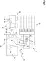
- Fig. 1 shows a harvesting machine 1, in this case a forage harvester, a tractor 20, and a trailer 12 attached to it, in this case a loading wagon.
- the tractor 20 and the trailer 12 form a team 10, which together with the harvesting machine 1 forms a vehicle combination according to the invention.
- the harvesting machine 1 has an automatic transfer device 3 which is connected to a camera 4 on the transfer device 2, via which it can determine which areas of the loading space 13 are more heavily loaded with crop 30 and which are less heavily loaded.
- the harvesting machine 1 also has a first processing unit 7 which can determine a harvesting machine speed of the harvesting machine 1 (e.g. using GPS data). It is also connected to an input unit 6 which is arranged within reach of the driver 8 and optionally to the automatic transfer device 3. Furthermore, it is coupled to a first transmitting device 5 which in this case is designed as a transmitting-receiving device.
- a first receiving device 15 is provided, which is also designed as a transmitting-receiving device and is compatible with the first transmitting device 5, so that they can communicate with each other wirelessly via a first transmission path 25.
- the first receiving device 15 is connected to a second processing unit 16 of the trailer 12, which in turn is connected to a second transmitting device 17.
- the latter can communicate with a second receiving device 22 of the tractor 20 via a second transmission path 26, in this case wired according to the ISOBUS standard. More precisely, the trailer 12 can control functions of the tractor 20 via the second transmission path 26 using TIM (Tractor Implement Management).
- Both the second transmitting device 17 and the second receiving device 22 are designed as transmitting-receiving devices.
- the second receiving device 22 is connected via a third processing unit 23 to a speed controller 24 of the tractor 20, which can set the speed of a driven axle 21 of the tractor 20 and thus influence an actual speed of the tractor 20.
- the first processing unit 7 determines a target speed for the tractor 20, which is sent to the first receiving device 15 as a first control signal by means of the first transmitting device 5 and is received by the latter.
- the received first control signal is decoded by the second processing unit 16 and the target speed contained therein is re-encoded in a second control signal in accordance with the communication standard of the second transmission path 26.
- the second control signal is then sent by means of the second sensor unit 17 and received by the second receiving unit 22.
- the target speed contained is extracted by the third processing unit 23 and sent to the speed controller 24, which then operates the driven axle 21 in such a way that, with a slip-free drive, the actual speed of the tractor 20 corresponds to the target speed.
- Fig. 2 shows a simplified schematic of a first lane 32 for the harvesting machine 1 and a second lane 33 for the trailer 10.
- the harvesting machine 1 and the trailer 10 initially drive straight ahead and then go into a curve, in which the harvesting machine 1 drives on a first curve radius r1 and the trailer 10 on a second curve radius r2.
- the actual speeds should match when driving straight ahead, while when cornering the outer unit should drive faster than the inner unit. This is taken into account in the method according to the invention, which is now described using the flow chart of Fig. 3 is explained.
- a calibration factor is initialized in a first step S100, normally with the value 1.0.
- the first processing unit 7 determines a harvesting machine speed of the harvesting machine 1 and initializes the target speed with this value.
- step S120 it is checked whether the lane 32 of the harvesting machine 1 is currently running straight ahead. If this is the case, it is checked in step S130 whether the relative positions of the trailer 10 with respect to the harvesting machine 1 should be changed.
- the corresponding request to change the relative position can be entered by the driver 8 via the input unit 6.
- the automatic transfer device 3 could also send a corresponding request to the processing unit 7.
- the latter in particular can serve the purpose of moving the loading area 14 forwards or backwards within the loading space 13 without having to change the setting of the transfer device 2.
- the value for the target speed is increased (e.g. by a specified amount such as 1 km/h) or reduced in step S140.
- the method continues with step S150, where it is checked whether calibration is necessary. This can be triggered, for example, by the driver if he determines that the actual speed of the trailer 10 does not match that of the harvesting machine 1, although this should currently be the case.
- step S 160 After which the method continues with step S250.
- step S120 If it is determined in step S120 that the lane 32 does not run straight, i.e. that the harvesting machine 1 is cornering, the first curve radius r1 is determined in step S200 and from this the second curve radius r2. To achieve the latter, the setting of the transfer device 2 is determined, from which it can be concluded whether the harvesting machine 1 is the unit on the outside of the curve or the unit on the inside of the curve. If this information is combined with the selected front attachment width of the harvesting machine 1, the second curve radius r2 can be determined from the first curve radius r1. The target speed can then be calculated from the ratio of the curve radii r1, r2 and the harvesting machine speed, so that the method can continue at step S250.
- step S250 the target speed is multiplied by the calibration factor, i.e. if the calibration factor is 1.0, the target speed remains unchanged.
- the previous method steps can be carried out at least predominantly by means of the first processing unit 7.
- step S300 There, the first control signal, which contains the target speed, is sent by the first transmitting device 5 and received by the first receiving device 15 in step S310 before it is decoded by the second processing unit 16 and the second control signal is created.
- step S320 the second control signal, which also contains the target speed, is sent by the second transmitting device 17 and received by the second receiving device 22 in step S330.
- the third processing unit determines the target speed from the second control signal and sends it to the speed controller 24.
- the speed controller 24 then sets the actual speed in accordance with the target speed in step S340. Due to the calibration, a given slip is taken into account in the transmitted target speed.
- step S350 it is checked whether the setting of the transfer device 2 should be changed, normally in order to change the position of the loading area 14. This can be triggered in particular by the automatic transfer device 3, but alternatively the driver 8 could also make a corresponding change to the setting via the input unit 6. If requested, the setting of the transfer device 2 is changed in step S360, after which the method returns to step S110. If not, the method returns immediately to step S110.
Landscapes
- Life Sciences & Earth Sciences (AREA)
- Environmental Sciences (AREA)
- Control Of Position, Course, Altitude, Or Attitude Of Moving Bodies (AREA)
Claims (14)
- Procédé de commande d'un attelage (10) composé d'un tracteur (20) et d'une remorque (12) attelée à celui-ci, accompagnant une machine de récolte (1), et vers lequel la machine de récolte (1) transfère au moins de temps en temps du produit récolté (30) par un dispositif de transbordement (2), la machine de récolte (1) ayant un premier dispositif émetteur (5), qui émet un premier signal de commande (S300) pour influencer la position relative de la remorque (12) par rapport à la machine de récolte (1),procédé caractérisé en ce quela remorque (12) reçoit le premier signal de commande (S310) par un premier dispositif récepteur (15) et en fonction du premier signal de commande elle émet un second signal de commande (S320) par un second dispositif émetteur (17), ce signal de commande contenant une information de vitesse,* le tracteur (20) recevant le second signal de commande (S330) par un second dispositif récepteur (22) et réglant (S340) ainsi sa vitesse réelle en fonction de l'information de vitesse.
- Procédé selon la revendication 1,
caractérisé en ce quele second signal de commande prédéfinit une vitesse de consigne,* le tracteur (20) réglant (S340) sa vitesse réelle en fonction de la vitesse de consigne. - Procédé selon la revendication 2,
caractérisé en ce que
la vitesse de consigne est prédéfinie par le premier signal de commande. - Procédé selon l'une des revendications 2-3,
caractérisé en ce que
le premier signal de commande prédéfinit au moins de temps en temps une vitesse de consigne différente de la vitesse de la machine de récolte (1), pour modifier la position relative de la remorque (12). - Procédé selon les revendications 2, 3 ou 4,
caractérisé en ce que
on effectue un calibrage (S160) de la vitesse de consigne de façon à la faire varier d'un coefficient de calibrage pour compenser l'écart entre la vitesse réelle et la vitesse de consigne produite par le glissement. - Procédé selon la revendication 5,
caractérisé en ce que
le calibrage (S160) se fait du côté de la machine de récolte (1) pour que la vitesse de consigne calibrée soit prédéfinie par le premier signal de commande. - Procédé selon l'une des revendications 2 à 6,
caractérisé en ce que
dans un parcours en courbe, de la machine de récolte (1) et de l'attelage (10) circulant avec des rayons de courbure (r1, r2) différents, la vitesse de consigne est adaptée (S210) automatiquement en fonction des rayons de courbure (r1, r2) et de la vitesse de la machine de récolte (1). - Procédé selon la revendication 7,
caractérisé en ce que
le rayon de courbure (r2) de l'attelage (10) pour l'adaptation de la vitesse de consigne se détermine (S200) automatiquement en fonction du rayon de courbure (r1) de la machine de récolte (1) et de l'orientation du dispositif de transbordement (2) de la machine de récolte (1). - Procédé selon l'une des revendications précédentes,
caractérisé en ce que
la zone de chargement (14) dans la remorque (12) dans laquelle est transbordé le produit récolté (30) varie dans le temps (S140, S360). - Procédé selon la revendication 9,
caractérisé en ce que
la zone de chargement (14) est modifiée par le changement de la position relative de la remorque (12) en ce que l'on prédétermine de temps en temps une vitesse de consigne qui correspond (S140) à une vitesse réelle différente de la vitesse de la machine de récolte (1). - Procédé selon l'une des revendications 9-10,
caractérisé en ce que
la zone de chargement (14) est modifiée (S360) par le changement du réglage du dispositif de transbordement (2). - Procédé selon l'une des revendications 9 à 11,
caractérisé en ce que
la zone de chargement (14) est modifiée automatiquement par un automatisme de transbordement (3) de la machine de récolte (1). - Procédé selon l'une des revendications 9 à 12,
caractérisé en ce que
la zone de chargement (14) est modifiée en fonction des entrées faites par le conducteur (8) de la machine de récolte (1). - Combinaison de véhicules comprenant une machine de récolte (1) et un attelage (10) avec un tracteur (20) et une remorque (12) attelée à celui-ci,- la machine de récolte (1) étant réalisée pour transborder le produit de récolte (30) à la remorque (12) par un dispositif de transbordement (2) et comprenant un premier dispositif émetteur (5) qui émet (S300) un premier signal de commande pour influencer la position relative de la remorque (12) par rapport à la machine de récolte (1),- la remorque (12) ayant un premier dispositif récepteur (15) pour recevoir (S310) le premier signal de commande et un second dispositif émetteur (17) pour émettre (S320) un second signal de commande en fonction du premier signal de commande, le second signal contenant une information de vitesse, et- le tracteur (20) ayant un second dispositif récepteur (22) pour recevoir (S330) le second signal de commande et un régulateur de vitesse (24) pour régler (S340) la vitesse réelle du tracteur (20) en fonction de l'information de vitesse.
Applications Claiming Priority (1)
| Application Number | Priority Date | Filing Date | Title |
|---|---|---|---|
| DE102021120949.8A DE102021120949A1 (de) | 2021-08-11 | 2021-08-11 | Verfahren zum Steuern eines eine Erntemaschine begleitenden Gespanns |
Publications (2)
| Publication Number | Publication Date |
|---|---|
| EP4133932A1 EP4133932A1 (fr) | 2023-02-15 |
| EP4133932B1 true EP4133932B1 (fr) | 2024-10-02 |
Family
ID=82786756
Family Applications (1)
| Application Number | Title | Priority Date | Filing Date |
|---|---|---|---|
| EP22188041.2A Active EP4133932B1 (fr) | 2021-08-11 | 2022-08-01 | Méthode de commande d'une remorque accompagnant une machine de récolte |
Country Status (3)
| Country | Link |
|---|---|
| EP (1) | EP4133932B1 (fr) |
| DE (1) | DE102021120949A1 (fr) |
| DK (1) | DK4133932T3 (fr) |
Family Cites Families (4)
| Publication number | Priority date | Publication date | Assignee | Title |
|---|---|---|---|---|
| DE10064860A1 (de) | 2000-12-23 | 2002-06-27 | Claas Selbstfahr Erntemasch | Einrichtung zur Optimierung der Überladung von Erntegut an landwirtschaftlichen Fahrzeugen |
| DE102010043854B4 (de) * | 2010-11-12 | 2016-01-14 | Deere & Company | Steueranordnung zur Kontrolle des Überladens landwirtschaftlichen Ernteguts von einer Erntemaschine auf ein Transportfahrzeug |
| DE102011002071A1 (de) * | 2011-04-15 | 2012-10-18 | Claas Selbstfahrende Erntemaschinen Gmbh | System und Verfahren zur Steuerung der Erntegutüberladung |
| DE102014113874A1 (de) * | 2014-09-25 | 2016-03-31 | Claas Selbstfahrende Erntemaschinen Gmbh | Verfahren zum Überladen bei Erntemaschinen |
-
2021
- 2021-08-11 DE DE102021120949.8A patent/DE102021120949A1/de not_active Withdrawn
-
2022
- 2022-08-01 EP EP22188041.2A patent/EP4133932B1/fr active Active
- 2022-08-01 DK DK22188041.2T patent/DK4133932T3/da active
Also Published As
| Publication number | Publication date |
|---|---|
| DK4133932T3 (da) | 2024-12-16 |
| EP4133932A1 (fr) | 2023-02-15 |
| DE102021120949A1 (de) | 2023-02-16 |
Similar Documents
| Publication | Publication Date | Title |
|---|---|---|
| EP3593620B1 (fr) | Système de récolte | |
| EP2130423B1 (fr) | Véhicule agricole et procédé de fonctionnement correspondant | |
| EP1219158B2 (fr) | Dispositif pour optimiser le transbordement de produits de récolte à un véhicule agricole | |
| EP2510775B1 (fr) | Système et procédé de commande du transfert de récoltes | |
| EP1645178B1 (fr) | Système d'assistance pour le transfert | |
| EP2266383B1 (fr) | Dispositif de commande pour le contrôle du transfert de récoltes agricoles d'une moissonneuse sur un véhicule de transport comportant un récipient de chargement | |
| EP2936969B1 (fr) | Combinaison d'un véhicule de traction et d'une moissonneuse tirée par celui-ci | |
| EP2893797B1 (fr) | Dispositif de récolte | |
| EP2100495B2 (fr) | Moissonneuse agricole dotée d'une goulotte de transbordement | |
| WO2013087275A1 (fr) | Procédé et dispositif pour régler l'avance d'une première machine automotrice par rapport à une seconde machine automotrice | |
| EP2302995A1 (fr) | Dispositif de commande pour contrôler la surcharge de récolte agricole d une moissonneuse sur un véhicule de transport | |
| EP3970471A1 (fr) | Procédé de commande de surcharge de cultures récoltées | |
| EP3689118A1 (fr) | Outil de travail agricole, timon et combinaison de véhicule de traction et d'outil de travail | |
| EP1685759B2 (fr) | Système pour l'alimentation uniforme des machines de travail | |
| EP4272541A1 (fr) | Combinaison et procédé de fonctionnement d'une combinaison | |
| EP4430942A1 (fr) | Combinaison, procédé de fonctionnement d'une combinaison et presse à balles | |
| EP4133932B1 (fr) | Méthode de commande d'une remorque accompagnant une machine de récolte | |
| EP4272542A1 (fr) | Combinaison et procédé de fonctionnement d'une combinaison | |
| DE102022111005A1 (de) | Kombination und Verfahren zum Betreiben einer Kombination | |
| EP4434315A1 (fr) | Attelage agricole pour véhicules destiné à faucher des fourrages | |
| DE102018215263A1 (de) | Selbstfahrende Erntemaschine mit einer Überladeeinrichtung | |
| EP4424132A1 (fr) | Attelage agricole pour véhicules destiné à faucher des fourrages | |
| DE102022111006A1 (de) | Verfahren zum Betreiben einer Kombination und Kombination | |
| EP4640038A1 (fr) | Combinaison, procédé de fonctionnement d'une combinaison et presse à balles | |
| EP4490995A1 (fr) | Procédé de fonctionnement d'un attelage agricole |
Legal Events
| Date | Code | Title | Description |
|---|---|---|---|
| PUAI | Public reference made under article 153(3) epc to a published international application that has entered the european phase |
Free format text: ORIGINAL CODE: 0009012 |
|
| STAA | Information on the status of an ep patent application or granted ep patent |
Free format text: STATUS: THE APPLICATION HAS BEEN PUBLISHED |
|
| AK | Designated contracting states |
Kind code of ref document: A1 Designated state(s): AL AT BE BG CH CY CZ DE DK EE ES FI FR GB GR HR HU IE IS IT LI LT LU LV MC MK MT NL NO PL PT RO RS SE SI SK SM TR |
|
| P01 | Opt-out of the competence of the unified patent court (upc) registered |
Effective date: 20230517 |
|
| STAA | Information on the status of an ep patent application or granted ep patent |
Free format text: STATUS: REQUEST FOR EXAMINATION WAS MADE |
|
| 17P | Request for examination filed |
Effective date: 20230719 |
|
| RBV | Designated contracting states (corrected) |
Designated state(s): AL AT BE BG CH CY CZ DE DK EE ES FI FR GB GR HR HU IE IS IT LI LT LU LV MC MK MT NL NO PL PT RO RS SE SI SK SM TR |
|
| GRAP | Despatch of communication of intention to grant a patent |
Free format text: ORIGINAL CODE: EPIDOSNIGR1 |
|
| STAA | Information on the status of an ep patent application or granted ep patent |
Free format text: STATUS: GRANT OF PATENT IS INTENDED |
|
| GRAS | Grant fee paid |
Free format text: ORIGINAL CODE: EPIDOSNIGR3 |
|
| INTG | Intention to grant announced |
Effective date: 20240705 |
|
| GRAA | (expected) grant |
Free format text: ORIGINAL CODE: 0009210 |
|
| STAA | Information on the status of an ep patent application or granted ep patent |
Free format text: STATUS: THE PATENT HAS BEEN GRANTED |
|
| AK | Designated contracting states |
Kind code of ref document: B1 Designated state(s): AL AT BE BG CH CY CZ DE DK EE ES FI FR GB GR HR HU IE IS IT LI LT LU LV MC MK MT NL NO PL PT RO RS SE SI SK SM TR |
|
| REG | Reference to a national code |
Ref country code: GB Ref legal event code: FG4D Free format text: NOT ENGLISH |
|
| REG | Reference to a national code |
Ref country code: CH Ref legal event code: EP |
|
| REG | Reference to a national code |
Ref country code: IE Ref legal event code: FG4D Free format text: LANGUAGE OF EP DOCUMENT: GERMAN |
|
| REG | Reference to a national code |
Ref country code: DE Ref legal event code: R096 Ref document number: 502022001792 Country of ref document: DE |
|
| REG | Reference to a national code |
Ref country code: DK Ref legal event code: T3 Effective date: 20241212 |
|
| REG | Reference to a national code |
Ref country code: NL Ref legal event code: FP |
|
| REG | Reference to a national code |
Ref country code: LT Ref legal event code: MG9D |
|
| PG25 | Lapsed in a contracting state [announced via postgrant information from national office to epo] |
Ref country code: IS Free format text: LAPSE BECAUSE OF FAILURE TO SUBMIT A TRANSLATION OF THE DESCRIPTION OR TO PAY THE FEE WITHIN THE PRESCRIBED TIME-LIMIT Effective date: 20250202 Ref country code: PT Free format text: LAPSE BECAUSE OF FAILURE TO SUBMIT A TRANSLATION OF THE DESCRIPTION OR TO PAY THE FEE WITHIN THE PRESCRIBED TIME-LIMIT Effective date: 20250203 Ref country code: HR Free format text: LAPSE BECAUSE OF FAILURE TO SUBMIT A TRANSLATION OF THE DESCRIPTION OR TO PAY THE FEE WITHIN THE PRESCRIBED TIME-LIMIT Effective date: 20241002 |
|
| PG25 | Lapsed in a contracting state [announced via postgrant information from national office to epo] |
Ref country code: FI Free format text: LAPSE BECAUSE OF FAILURE TO SUBMIT A TRANSLATION OF THE DESCRIPTION OR TO PAY THE FEE WITHIN THE PRESCRIBED TIME-LIMIT Effective date: 20241002 |
|
| PG25 | Lapsed in a contracting state [announced via postgrant information from national office to epo] |
Ref country code: BG Free format text: LAPSE BECAUSE OF FAILURE TO SUBMIT A TRANSLATION OF THE DESCRIPTION OR TO PAY THE FEE WITHIN THE PRESCRIBED TIME-LIMIT Effective date: 20241002 |
|
| PG25 | Lapsed in a contracting state [announced via postgrant information from national office to epo] |
Ref country code: ES Free format text: LAPSE BECAUSE OF FAILURE TO SUBMIT A TRANSLATION OF THE DESCRIPTION OR TO PAY THE FEE WITHIN THE PRESCRIBED TIME-LIMIT Effective date: 20241002 |
|
| PG25 | Lapsed in a contracting state [announced via postgrant information from national office to epo] |
Ref country code: NO Free format text: LAPSE BECAUSE OF FAILURE TO SUBMIT A TRANSLATION OF THE DESCRIPTION OR TO PAY THE FEE WITHIN THE PRESCRIBED TIME-LIMIT Effective date: 20250102 |
|
| PG25 | Lapsed in a contracting state [announced via postgrant information from national office to epo] |
Ref country code: LV Free format text: LAPSE BECAUSE OF FAILURE TO SUBMIT A TRANSLATION OF THE DESCRIPTION OR TO PAY THE FEE WITHIN THE PRESCRIBED TIME-LIMIT Effective date: 20241002 Ref country code: GR Free format text: LAPSE BECAUSE OF FAILURE TO SUBMIT A TRANSLATION OF THE DESCRIPTION OR TO PAY THE FEE WITHIN THE PRESCRIBED TIME-LIMIT Effective date: 20250103 |
|
| PG25 | Lapsed in a contracting state [announced via postgrant information from national office to epo] |
Ref country code: CZ Free format text: LAPSE BECAUSE OF FAILURE TO SUBMIT A TRANSLATION OF THE DESCRIPTION OR TO PAY THE FEE WITHIN THE PRESCRIBED TIME-LIMIT Effective date: 20241002 Ref country code: PL Free format text: LAPSE BECAUSE OF FAILURE TO SUBMIT A TRANSLATION OF THE DESCRIPTION OR TO PAY THE FEE WITHIN THE PRESCRIBED TIME-LIMIT Effective date: 20241002 |
|
| PG25 | Lapsed in a contracting state [announced via postgrant information from national office to epo] |
Ref country code: RS Free format text: LAPSE BECAUSE OF FAILURE TO SUBMIT A TRANSLATION OF THE DESCRIPTION OR TO PAY THE FEE WITHIN THE PRESCRIBED TIME-LIMIT Effective date: 20250102 |
|
| PG25 | Lapsed in a contracting state [announced via postgrant information from national office to epo] |
Ref country code: SM Free format text: LAPSE BECAUSE OF FAILURE TO SUBMIT A TRANSLATION OF THE DESCRIPTION OR TO PAY THE FEE WITHIN THE PRESCRIBED TIME-LIMIT Effective date: 20241002 |
|
| REG | Reference to a national code |
Ref country code: DE Ref legal event code: R097 Ref document number: 502022001792 Country of ref document: DE |
|
| PG25 | Lapsed in a contracting state [announced via postgrant information from national office to epo] |
Ref country code: EE Free format text: LAPSE BECAUSE OF FAILURE TO SUBMIT A TRANSLATION OF THE DESCRIPTION OR TO PAY THE FEE WITHIN THE PRESCRIBED TIME-LIMIT Effective date: 20241002 |
|
| PG25 | Lapsed in a contracting state [announced via postgrant information from national office to epo] |
Ref country code: RO Free format text: LAPSE BECAUSE OF FAILURE TO SUBMIT A TRANSLATION OF THE DESCRIPTION OR TO PAY THE FEE WITHIN THE PRESCRIBED TIME-LIMIT Effective date: 20241002 |
|
| PG25 | Lapsed in a contracting state [announced via postgrant information from national office to epo] |
Ref country code: SK Free format text: LAPSE BECAUSE OF FAILURE TO SUBMIT A TRANSLATION OF THE DESCRIPTION OR TO PAY THE FEE WITHIN THE PRESCRIBED TIME-LIMIT Effective date: 20241002 |
|
| PLBE | No opposition filed within time limit |
Free format text: ORIGINAL CODE: 0009261 |
|
| STAA | Information on the status of an ep patent application or granted ep patent |
Free format text: STATUS: NO OPPOSITION FILED WITHIN TIME LIMIT |
|
| PG25 | Lapsed in a contracting state [announced via postgrant information from national office to epo] |
Ref country code: SE Free format text: LAPSE BECAUSE OF FAILURE TO SUBMIT A TRANSLATION OF THE DESCRIPTION OR TO PAY THE FEE WITHIN THE PRESCRIBED TIME-LIMIT Effective date: 20241002 |
|
| 26N | No opposition filed |
Effective date: 20250703 |
|
| PGFP | Annual fee paid to national office [announced via postgrant information from national office to epo] |
Ref country code: NL Payment date: 20250821 Year of fee payment: 4 |
|
| PGFP | Annual fee paid to national office [announced via postgrant information from national office to epo] |
Ref country code: DK Payment date: 20250821 Year of fee payment: 4 Ref country code: DE Payment date: 20250819 Year of fee payment: 4 |
|
| PGFP | Annual fee paid to national office [announced via postgrant information from national office to epo] |
Ref country code: IT Payment date: 20250901 Year of fee payment: 4 |
|
| PGFP | Annual fee paid to national office [announced via postgrant information from national office to epo] |
Ref country code: BE Payment date: 20250820 Year of fee payment: 4 |
|
| PGFP | Annual fee paid to national office [announced via postgrant information from national office to epo] |
Ref country code: AT Payment date: 20251020 Year of fee payment: 4 |
|
| REG | Reference to a national code |
Ref country code: CH Ref legal event code: H13 Free format text: ST27 STATUS EVENT CODE: U-0-0-H10-H13 (AS PROVIDED BY THE NATIONAL OFFICE) Effective date: 20260324 |
|
| PG25 | Lapsed in a contracting state [announced via postgrant information from national office to epo] |
Ref country code: MC Free format text: LAPSE BECAUSE OF FAILURE TO SUBMIT A TRANSLATION OF THE DESCRIPTION OR TO PAY THE FEE WITHIN THE PRESCRIBED TIME-LIMIT Effective date: 20241002 |
|
| PG25 | Lapsed in a contracting state [announced via postgrant information from national office to epo] |
Ref country code: LU Free format text: LAPSE BECAUSE OF NON-PAYMENT OF DUE FEES Effective date: 20250801 |
|
| PG25 | Lapsed in a contracting state [announced via postgrant information from national office to epo] |
Ref country code: CH Free format text: LAPSE BECAUSE OF NON-PAYMENT OF DUE FEES Effective date: 20250831 |