EP4133955A1 - Dispositif de génération d'aérosol par laser et procédé de commande de chauffage associé - Google Patents
Dispositif de génération d'aérosol par laser et procédé de commande de chauffage associé Download PDFInfo
- Publication number
- EP4133955A1 EP4133955A1 EP21935322.4A EP21935322A EP4133955A1 EP 4133955 A1 EP4133955 A1 EP 4133955A1 EP 21935322 A EP21935322 A EP 21935322A EP 4133955 A1 EP4133955 A1 EP 4133955A1
- Authority
- EP
- European Patent Office
- Prior art keywords
- aerosol
- laser
- generating article
- generation device
- forming substrate
- Prior art date
- Legal status (The legal status is an assumption and is not a legal conclusion. Google has not performed a legal analysis and makes no representation as to the accuracy of the status listed.)
- Granted
Links
Images






Classifications
-
- A—HUMAN NECESSITIES
- A24—TOBACCO; CIGARS; CIGARETTES; SIMULATED SMOKING DEVICES; SMOKERS' REQUISITES
- A24F—SMOKERS' REQUISITES; MATCH BOXES; SIMULATED SMOKING DEVICES
- A24F40/00—Electrically operated smoking devices; Component parts thereof; Manufacture thereof; Maintenance or testing thereof; Charging means specially adapted therefor
- A24F40/40—Constructional details, e.g. connection of cartridges and battery parts
- A24F40/46—Shape or structure of electric heating means
-
- A—HUMAN NECESSITIES
- A24—TOBACCO; CIGARS; CIGARETTES; SIMULATED SMOKING DEVICES; SMOKERS' REQUISITES
- A24D—CIGARS; CIGARETTES; TOBACCO SMOKE FILTERS; MOUTHPIECES OF CIGARS OR CIGARETTES; MANUFACTURE OF TOBACCO SMOKE FILTERS OR MOUTHPIECES
- A24D1/00—Cigars; Cigarettes
- A24D1/20—Cigarettes specially adapted for simulated smoking devices
-
- A—HUMAN NECESSITIES
- A24—TOBACCO; CIGARS; CIGARETTES; SIMULATED SMOKING DEVICES; SMOKERS' REQUISITES
- A24F—SMOKERS' REQUISITES; MATCH BOXES; SIMULATED SMOKING DEVICES
- A24F40/00—Electrically operated smoking devices; Component parts thereof; Manufacture thereof; Maintenance or testing thereof; Charging means specially adapted therefor
- A24F40/20—Devices using solid inhalable precursors
-
- A—HUMAN NECESSITIES
- A24—TOBACCO; CIGARS; CIGARETTES; SIMULATED SMOKING DEVICES; SMOKERS' REQUISITES
- A24F—SMOKERS' REQUISITES; MATCH BOXES; SIMULATED SMOKING DEVICES
- A24F40/00—Electrically operated smoking devices; Component parts thereof; Manufacture thereof; Maintenance or testing thereof; Charging means specially adapted therefor
- A24F40/50—Control or monitoring
-
- A—HUMAN NECESSITIES
- A24—TOBACCO; CIGARS; CIGARETTES; SIMULATED SMOKING DEVICES; SMOKERS' REQUISITES
- A24F—SMOKERS' REQUISITES; MATCH BOXES; SIMULATED SMOKING DEVICES
- A24F40/00—Electrically operated smoking devices; Component parts thereof; Manufacture thereof; Maintenance or testing thereof; Charging means specially adapted therefor
- A24F40/50—Control or monitoring
- A24F40/57—Temperature control
-
- A—HUMAN NECESSITIES
- A24—TOBACCO; CIGARS; CIGARETTES; SIMULATED SMOKING DEVICES; SMOKERS' REQUISITES
- A24F—SMOKERS' REQUISITES; MATCH BOXES; SIMULATED SMOKING DEVICES
- A24F7/00—Mouthpieces for pipes; Mouthpieces for cigar or cigarette holders
-
- H—ELECTRICITY
- H01—ELECTRIC ELEMENTS
- H01S—DEVICES USING THE PROCESS OF LIGHT AMPLIFICATION BY STIMULATED EMISSION OF RADIATION [LASER] TO AMPLIFY OR GENERATE LIGHT; DEVICES USING STIMULATED EMISSION OF ELECTROMAGNETIC RADIATION IN WAVE RANGES OTHER THAN OPTICAL
- H01S3/00—Lasers, i.e. devices using stimulated emission of electromagnetic radiation in the infrared, visible or ultraviolet wave range
-
- H—ELECTRICITY
- H05—ELECTRIC TECHNIQUES NOT OTHERWISE PROVIDED FOR
- H05B—ELECTRIC HEATING; ELECTRIC LIGHT SOURCES NOT OTHERWISE PROVIDED FOR; CIRCUIT ARRANGEMENTS FOR ELECTRIC LIGHT SOURCES, IN GENERAL
- H05B35/00—Electric light sources using a combination of different types of light generation
-
- H—ELECTRICITY
- H01—ELECTRIC ELEMENTS
- H01M—PROCESSES OR MEANS, e.g. BATTERIES, FOR THE DIRECT CONVERSION OF CHEMICAL ENERGY INTO ELECTRICAL ENERGY
- H01M2220/00—Batteries for particular applications
- H01M2220/30—Batteries in portable systems, e.g. mobile phone, laptop
Definitions
- the present disclosure relates to a laser-based aerosol generation device and a heating control method thereof, and more particularly, to an aerosol generation device capable of efficient heating while ensuring immediate aerosol generation through laser heating and a heating control method performed in the device.
- Some embodiments of the present disclosure are directed to providing an aerosol generation device capable of ensuring immediate aerosol generation and a heating control method performed in the device.
- Some embodiments of the present disclosure are also directed to providing an aerosol generation device having an efficient heating function and a heating control method performed in the device.
- Some embodiments of the present disclosure are also directed to providing an aerosol generation device having a precise heating control function and a heating control method performed in the device.
- Some embodiments of the present disclosure provide an aerosol generation device including an aerosol-generating article and a laser radiation part configured to radiate laser and heat the aerosol-generating article to generate an aerosol, wherein at least one of the aerosol-generating article and the laser radiation part is configured to move during the heating.
- the aerosol-generating article may include a cylindrical aerosol-forming substrate.
- the aerosol-generating article may further include a holder configured to rotate the aerosol-forming substrate, and a site irradiated with the laser may change due to the rotation.
- a thickness of the aerosol-forming substrate may be 2 mm or less.
- the aerosol-generating article may include a flat-type aerosol-forming substrate.
- the aerosol-generating article may linearly move in a longitudinal direction or a direction perpendicular to the longitudinal direction, and a site irradiated with the laser may change due to the linear movement.
- the aerosol generation device may further include a tubular laser guide part configured to guide the radiated laser to the aerosol-generating article.
- the aerosol generation device may further include a laser reflection part disposed below the aerosol-generating article to reflect the radiated laser toward the aerosol-generating article and a mouthpiece part disposed above the aerosol-generating article.
- the aerosol generation device may further include a controller configured to control heating of the aerosol-generating article on the basis of a radiation area of the laser.
- the aerosol generation device may further include a controller configured to control heating of the aerosol-generating article on the basis of characteristics of the laser reflected from the aerosol-generating article.
- immediate aerosol generation can be ensured. Specifically, by heating a surface of the thin aerosol-forming substrate with laser, an aerosol can be generated immediately without a preheating time. Accordingly, a smoking standby time can be minimized, and user satisfaction with the aerosol generation device can be improved.
- an aerosol-generating article and/or a laser radiation part can be configured to move during the heating. Also, as a site irradiated with the laser changes due to such movement, the entire aerosol-forming substrate can be effectively heated even when the laser radiation part is provided as a small number of laser radiation parts.
- heating control can be performed on the basis of a radiation area of the laser, characteristics of the laser reflected from the aerosol-generating article, etc. For example, by setting the radiation area of the laser to an appropriate size, more precise temperature control can be performed, and a problem in which a local surface of the aerosol-forming substrate is carbonized due to the laser being focused thereon can also be prevented. Alternatively, by accurately determining, on the basis of characteristics of the reflected laser, whether carbonization of the aerosol-forming substrate has occurred, a problem in which a carbonized site is heated again can also be prevented.
- first, second, A, B, (a), and (b) may be used. Such terms are only used for distinguishing one component from another component, and the essence, order, sequence, or the like of the corresponding component is not limited by the terms.
- a certain component is described as being “connected,” “coupled,” or “linked” to another component, it should be understood that, although the component may be directly connected or linked to the other component, still another component may also be “connected,” “coupled,” or “linked” between the two components.
- aerosol-forming substrate may refer to a material that is able to form an aerosol.
- the aerosol may include a volatile compound.
- the aerosol-forming substrate may be a solid or liquid.
- solid aerosol-forming substrates may include solid materials based on tobacco raw materials such as reconstituted tobacco leaves, shredded tobacco, and reconstituted tobacco
- liquid aerosol-forming substrates may include liquid compositions based on nicotine, tobacco extracts, and/or various flavoring agents.
- the scope of the present disclosure is not limited to the above-listed examples.
- a liquid aerosol-forming substrate may include at least one of propylene glycol (PG) and glycerin (GLY) and may further include at least one of ethylene glycol, dipropylene glycol, diethylene glycol, triethylene glycol, tetraethylene glycol, and oleyl alcohol.
- the aerosol-forming substrate may further include at least one of nicotine, moisture, and a flavoring material.
- the aerosol-forming substrate may further include various additives such as cinnamon and capsaicin.
- the aerosol-forming substrate may not only include a liquid material with high fluidity but also include a material in the form of a gel or a solid. In this way, as the components constituting the aerosol-forming substrate, various materials may be selected according to embodiments, and composition ratios thereof may also vary according to embodiments.
- liquid may refer to a liquid aerosol-forming substrate.
- aerosol generation device may refer to a device that generates an aerosol using an aerosol-forming substrate in order to generate an aerosol that can be inhaled directly into the user's lungs through the user's mouth.
- aerosol-generating article may refer to an article that is able to generate an aerosol.
- the aerosol-generating article may include an aerosol-forming substrate.
- puff refers to inhalation by a user, and the inhalation may be a situation in which a user draws smoke into his or her oral cavity, nasal cavity, or lungs through the mouth or nose.
- longitudinal direction may refer to a direction corresponding to a longitudinal axis of an aerosol generation device or aerosol-generating article.
- sheet may refer to a thin layer component whose width and length are substantially larger than a thickness thereof.
- sheet may be interchangeably used with the term “web” or “film” in the art.
- FIG. 1 is an exemplary view schematically illustrating an aerosol generation device 100 according to some embodiments of the present disclosure.
- the aerosol generation device 100 may include a housing, a mouthpiece part 110, a heater part, a battery 130, and a controller 120.
- the aerosol generation device 100 may further include general-purpose components other than the components illustrated in FIG. 1 .
- the aerosol generation device 100 may further include an input module (e.g., a button, a touchable display, etc.) for receiving a command or the like from a user and an output module (e.g., a light emitting module (LED), a display, or a vibration module) configured to output a state, smoking information, or the like of the aerosol generation device 100.
- an input module e.g., a button, a touchable display, etc.
- an output module e.g., a light emitting module (LED), a display, or a vibration module
- the housing may form an exterior of the aerosol generation device 100.
- the housing may be implemented using a material that can protect components inside the housing from an external force.
- the housing may form a space into which an aerosol-generating article 150 is inserted.
- the housing may be formed of a structure that allows the aerosol-generating article 150 to be inserted into a heating space 141 therein.
- the housing may have a structure of which one surface is open (e.g., a front surface is open) or one portion is separated (e.g., an upper portion and a lower portion are separated), and a user may open the one surface or separate the one portion to insert (mount) the aerosol-generating article 150 into (on) the heating space 141.
- the mouthpiece part 110 may be disposed at one end of the aerosol generation device 100 and serve as a mouthpiece that comes into contact with the oral region of the user.
- the user may inhale an aerosol by making a puff through the mouthpiece part 110.
- the mouthpiece part 110 may be implemented in a form that occupies a portion of the housing or may be implemented in the form of a separate structure mounted on the aerosol generation device 100.
- the heater part may heat the aerosol-generating article 150 disposed in the heating space 141 to generate an aerosol.
- the operation of the heater part may be controlled by the controller 120.
- the heater part may include one or more laser radiation parts 140.
- the laser radiation part 140 may irradiate a surface of the aerosol-generating article 150 with laser to immediately generate an aerosol without a preheating time.
- the laser radiation part 140 is a module configured to emit (radiate) a laser beam and may be implemented using a semiconductor-type laser diode, for example, but the scope of the present disclosure is not limited thereto.
- the laser beam may be light having an infrared wavelength, but the scope of the present disclosure is not limited thereto.
- the laser radiation part 140 may also be referred to as "laser beam source 140."
- FIG. 1 illustrates an example in which the aerosol generation device 100 includes two laser radiation parts 140, but of course, the aerosol generation device 100 may include a single laser radiation part 140 or include three or more laser radiation parts 140.
- the aerosol-generating article 150 may include a solid aerosol-forming substrate 151.
- the aerosol-generating article 150 may consist of the aerosol-forming substrate 151 and a holder 152 thereof.
- the scope of the present disclosure is not limited thereto.
- the aerosol-generating article 150 may have a structure that allows a surface of the aerosol-forming substrate 151 to be exposed to the outside and directly heated by laser.
- the aerosol-generating article 150 may have a structure in which the aerosol-forming substrate 151 not surrounded by a wrapper is mounted on the holder 152.
- the scope of the present disclosure is not limited thereto.
- the aerosol-generating article 150 may be manufactured in the form of a cartridge.
- the aerosol-generating article 150 may be manufactured in a form in which the aerosol-forming substrate 151 is replaced after being exhausted.
- the scope of the present disclosure is not limited thereto.
- the aerosol-forming substrate 151 may be designed and manufactured so that the form, thickness, and/or size thereof vary. However, in order to make good use of the characteristics of a laser beam that heats a local surface, it may be preferable to manufacture the aerosol-forming substrate 151 to have a small thickness.
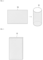
- the aerosol-forming substrate 151 may be manufactured in a cylindrical shape.
- a sheet-type (or flat-type) aerosol-forming substrate 153 e.g., a sheet-type tobacco material such as reconstituted tobacco leaves
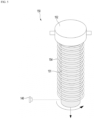
- the aerosol-forming substrate 151 may be easily heated. More specifically, even when only an outer surface of the aerosol-forming substrate 151 is heated by laser, due to the aerosol-forming substrate 151 having a small thickness, the inside of the aerosol-forming substrate 151 may also be heated, and an aerosol may be generated immediately. Also, as will be described below, the entire aerosol-forming substrate 151 may be easily heated due to rotation of the aerosol-forming substrate 151 (refer to description given below with reference to FIGS. 4 and 5 ).
- the aerosol-forming substrate 151 may be manufactured in a flat shape.
- a sheet-type aerosol-forming substrate e.g., 153
- the sheet-type aerosol-forming substrate e.g., 153
- the sheet-type aerosol-forming substrate e.g., 153
- immediate aerosol generation may be ensured by laser heating, and the entire aerosol-forming substrate 151 may be easily heated.
- the inside of the aerosol-forming substrate 151 may also be heated, and an aerosol may be generated immediately.
- the entire aerosol-forming substrate 151 may be easily heated due to linear movement of the aerosol-forming substrate 151 (refer to description given below with reference to FIG. 6 ).
- the aerosol-forming substrate 151 may also be manufactured in another form as illustrated in FIG. 2 or 3 .
- a thickness of the processed aerosol-forming substrate 151 or sheet-type aerosol-forming substrate may be less than or equal to about 5 mm, preferably, less than or equal to about 3 mm, 2 mm, or 1 mm. Within such numerical ranges, the inside of the aerosol-forming substrate 151 may also be sufficiently heated by the radiated laser.
- the size of the aerosol-forming substrate 151 may be appropriately determined in consideration of the size of the heating space 141, the number of times the aerosol-generating article 150 is smoked, etc.
- the size of the aerosol-forming substrate 151 may be determined on the basis of a target number of times the aerosol-generating article 150 is smoked.
- the present disclosure is not limited thereto.
- At least one of the aerosol-generating article 150 and the laser radiation part 140 may be configured to move during heating.
- a site irradiated with the laser that is, a site of the aerosol-forming substrate 151 that is irradiated with the laser or a heating point of the aerosol-forming substrate 151
- the movement may not only include rotation and linear movement but also include movement caused by angle adjustment at a fixed position.
- the movement of the aerosol-generating article 150 and the laser radiation part 140 may be implemented in a manual manner or an automatic manner. For example, the movement may be automatically performed by control of the controller 120. The present embodiment will be described in detail below with reference to FIGS. 4 to 8 .
- the battery 130 may supply power used to operate the aerosol generation device 100.
- the battery 130 may supply power to allow the heater part (e.g., laser radiation part 140) to heat the aerosol-forming substrate 151 included in the aerosol-generating article 150 and may supply power required for the operation of the controller 120.
- the heater part e.g., laser radiation part 140
- the controller 120 may control the overall operation of the aerosol generation device 100.
- the controller 120 may control the operation of the heater part (e.g., laser radiation part 140) and the battery 130 and may also control the operation of other components included in the aerosol generation device 100.
- the controller 120 may control the power supplied by the battery 130, the heating operation of the heater part (e.g., laser radiation part 140), and the like.
- the controller 120 may control a radiation intensity, a radiation shape, a radiation area, etc. of the laser radiation part 140 and may also control the movement of the laser radiation part 140 and/or aerosol-generating article 150.
- the controller 120 may check a state of each of the components of the aerosol generation device 100 and determine whether the aerosol generation device 100 is in an operable state.
- the controller 120 in response to detection of a user's puff, may control the battery 130 so that power is supplied to the laser radiation part 140.
- the controller 120 may perform control so that power is supplied to the laser radiation part 140 only upon a puff instead of being continuously supplied to the laser radiation part 140. In this case, the power consumption of the aerosol generation device 100 may be significantly reduced, and heating efficiency may be significantly improved.
- the controller 120 may be implemented with at least one processor.
- the processor may also be implemented with an array of a plurality of logic gates or implemented with a combination of a general-purpose microprocessor and a memory which stores a program that may be executed by the microprocessor.
- the controller 120 may also be implemented with other forms of hardware.
- the aerosol generation device 100 has been schematically described above with reference to FIGS. 1 to 3 .
- immediate aerosol generation may be ensured by employing the laser heating method and the aerosol-forming substrate 151 having a small thickness.
- an aerosol may be generated immediately without a preheating time. Accordingly, a smoking standby time may be minimized, and user satisfaction with the aerosol generation device 100 may be improved.
- the present embodiment relates to a method of heating the aerosol-generating article 150 on the basis of rotation of the laser radiation part 140 or aerosol-generating article 150.
- the laser radiation part 140 may radiate laser at a fixed position, and the aerosol-generating article 150 may slightly move upward (e.g., toward the mouthpiece part 110) with each rotation.
- the aerosol-generating article 150 may move downward with the rotation.
- the aerosol-forming substrate 151 may be heated. In this case, the entire aerosol-forming substrate 151 may be easily heated even with a small number of laser radiation parts 140.
- the rotation of the aerosol-generating article 150 or aerosol-forming substrate 151 may be implemented in various ways.
- the aerosol-generating article 150 may further include a rotation guide part 154 formed in a spiral shape (or in the shape of a spring).
- the rotation of the aerosol-generating article 150 may be implemented by the holder 152 rotating along the rotation guide part 154.
- the scope of the present disclosure is not limited thereto.
- the laser radiation part 140 may radiate laser while rotating around the aerosol-generating article 150.
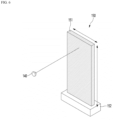
- the present embodiment relates to a method of heating the aerosol-generating article 150 on the basis of linear movement of the laser radiation part 140 or aerosol-generating article 150.
- the laser radiation part 140 may radiate laser at a fixed position, and the aerosol-generating article 150 may move in a longitudinal direction (that is, a vertical direction) or a direction perpendicular thereto (that is, a horizontal direction).
- the aerosol-forming substrate 151 may be heated. In this case, the entire aerosol-forming substrate 151 may be easily heated even with a small number of laser radiation parts 140.
- the linear movement of the aerosol-generating article 150 may be implemented in various ways and may be implemented in any way.
- the laser radiation part 140 may radiate laser while moving in the longitudinal direction or a direction perpendicular thereto.
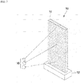
- the present embodiment relates to a method of heating the aerosol-generating article 150 on the basis of angle adjustment of the laser radiation part 140 or aerosol-generating article 150.
- the laser radiation part 140 may heat the aerosol-forming substrate 151 while changing an angle of radiation at a fixed position.
- the laser radiation part 140 may heat the aerosol-forming substrate 151 while changing a vertical angle or horizontal angle.
- the aerosol-forming substrate 151 may be heated.
- the entire aerosol-forming substrate 151 may be easily heated even with a small number of laser radiation parts 140.
- the laser radiation part 140 may radiate laser at a fixed angle, and a vertical or horizontal angle (slope) of the aerosol-generating article 150 may change.
- FIG. 7 illustrates an example in which a single laser radiation part 140 is disposed, but a plurality of laser radiation parts 140 may be disposed as mentioned above.
- a first laser radiation part configured to heat one surface of the aerosol-forming substrate 151 and a second laser radiation part configured to heat a surface other than (e.g., opposite to) the surface heated by the first laser radiation part may be disposed.
- the present embodiment relates to a method of heating the aerosol-generating article 150 on the basis of angle adjustment of laser radiation parts 140-1 and 140-2 and linear movement (or rotation) of the aerosol-generating article 150.
- FIG. 8 illustrates an example in which the plurality of laser radiation parts 140-1 and 140-2 are disposed, but of course, a single laser radiation part 140 may be disposed in some cases.
- a first laser radiation part 140-1 may radiate laser toward one surface of a flat-shaped aerosol-forming substrate 151 while changing an angle of radiation
- a second laser radiation part 140-2 may radiate laser toward another surface (e.g., the opposite surface) of the aerosol-forming substrate 151 while changing an angle of radiation
- the aerosol-generating article 150 may perform linear movement (or rotation).
- each of the laser radiation parts 140-1 and 140-2 may heat the aerosol-generating article 150 while changing a vertical angle
- the aerosol-generating article 150 may perform linear movement (e.g., linear reciprocation) in the horizontal direction (that is, the direction perpendicular to the longitudinal direction).
- each of the laser radiation parts 140-1 and 140-2 may heat the aerosol-generating article 150 while changing a horizontal angle, and the aerosol-generating article 150 may perform linear movement (e.g., linear reciprocation) in the vertical direction (that is, the longitudinal direction).
- the entire aerosol-forming substrate 151 may be easily heated, and a degree (distance) of movement of the aerosol-generating article 150 may be significantly reduced.
- the present embodiment relates to a method of addressing a problem in which efficiency of laser heating is degraded as an aerosol is generated, and in order to provide convenience of understanding, this problem will be described first with reference to FIG. 9 .
- an aerosol 155 may be formed around the aerosol-forming substrate 151.
- the aerosol 155 formed in this way may act as a factor that degrades laser heating efficiency.
- laser heating efficiency may be degraded due to absorption, scattering, etc. of a laser beam that occurs due to the aerosol 155 disposed on a laser radiation path. That is, the aerosol 155 may cause a problem in which energy of a laser beam that reaches the aerosol-forming substrate 151 is reduced.
- the heater part may further include a laser reflection part 142 as illustrated in FIG. 10 .
- the laser reflection part 142 may be disposed below the aerosol-generating article 150 and reflect the radiated laser toward the aerosol-generating article 150 disposed above. In this case, as the radiated laser bypasses the aerosol 155 around the aerosol-forming substrate 151 to reach the aerosol-forming substrate 151, or the laser is reflected toward an airflow (that is, upward), contact between the laser and the aerosol 155 may be minimized. Also, accordingly, the problem in which the laser heating efficiency is degraded due to the aerosol 155 may be addressed.
- the heater part may further include a laser guide part 143 configured to guide the radiated laser to the aerosol-forming substrate 151.
- the laser guide part 143 may be formed in the shape of a tube (e.g., a waveguide, a diffuser) and may be disposed in a form that passes through the aerosol 155 around the aerosol-forming substrate 151. In this case, without loss of energy, the radiated laser may reach the aerosol-forming substrate 151 through a path inside the laser guide part 143. Thus, the problem in which the laser heating efficiency is degraded due to the aerosol 155 may be addressed.
- the heating control method which will be described below may be implemented using one or more instructions executed by a computing module (e.g., the controller 120) including a processor. Also, hereinafter, in order to provide convenience of understanding, description will be continued assuming that the heating control method is performed by the controller 120 of the aerosol generation device 100 illustrated in FIG. 1 . Therefore, when the subject performing a specific step/operation is omitted, the specific step/operation may be understood as being performed by the illustrated module 120.
- a computing module e.g., the controller 120
- the specific step/operation may be understood as being performed by the illustrated module 120.
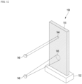
- the present embodiment relates to a method of performing heating control on the basis of a radiation area (or radiation shape) of laser.
- a heating temperature (or heating strength) is inevitably changed according to areas of regions 144 and 145 irradiated with the laser. For example, since an area of a first radiation region 144 is smaller than an area of a second radiation region 145, the first radiation region 144 may be heated at a higher temperature than the second radiation region 145. This is because the smaller the radiation area, the more the laser energy is concentrated, and the larger the radiation area, the more the laser energy is dispersed and thus the heating strength per unit area is decreased.
- the controller 120 may adjust the radiation area (that is, the size of the radiation area) to perform a precise heating control function for the aerosol-generating article 150.
- a specific method of heating control may vary.
- the controller 120 may increase or decrease the size of the radiation area on the basis of the heating temperature of the aerosol-generating article 150. For example, in response to determination that the heating temperature of the aerosol-generating article 150 is a reference value or higher, the controller 120 may increase the size of the radiation area. Alternatively, in response to determination that the heating temperature of the aerosol-generating article 150 is lower than the reference value, the controller 120 may decrease the size of the radiation area. According to such control, the heating temperature of the aerosol-generating article 150 may be precisely controlled.
- the controller 120 may increase or decrease the size of the radiation area on the basis of a heating state (e.g., degree of carbonization) of the aerosol-forming substrate 151. For example, in response to determination that a specific site of the aerosol-forming substrate 151 is carbonized (heated) to a reference value or more, the controller 120 may increase the size of the radiation area. Alternatively, in response to determination that a specific site of the aerosol-generating article 150 is carbonized (heated) less than the reference value, the controller 120 may decrease the size of the radiation area. According to such control, a problem in which a burnt taste develops during smoking may be significantly alleviated.
- a heating state e.g., degree of carbonization
- the controller 120 may increase or decrease the size of the radiation area on the basis of the passage of smoking time. Specifically, the controller 120 may heat the aerosol-generating article 150 with a relatively small radiation area for immediate aerosol generation at the beginning of smoking and may heat the aerosol-generating article 150 with a relatively large radiation area to prevent carbonization etc. in the middle of smoking. In some cases, in order to enhance a tobacco smoke taste towards the end of smoking, the controller 120 may heat the aerosol-generating article 150 with a relatively small radiation area again towards the end of smoking.
- a specific method of adjusting the radiation area of the laser may also vary.
- the radiation area of the laser may be adjusted by adjusting a focal length. This is because, when the focal length is changed while a distance between the laser radiation part 140 and the aerosol-generating article 150 is constant, the area irradiated with the laser is changed.
- a focal length may be adjusted using a focus-adjustable lens.
- the scope of the present disclosure is not limited thereto.
- a plurality of lenses with different characteristics may be provided, and the radiation area may be adjusted by changing (replacing) a lens of the laser radiation part 140 with another lens.
- the radiation area may be adjusted by adjusting the distance between the laser radiation part 140 and the aerosol-generating article 150. This is because, when the distance between the laser radiation part 140 and the aerosol-generating article 150 is changed when a focal length of the lens of the laser radiation part 140 is constant, the area radiated with the laser is changed.
- FIG. 13 is an exemplary flowchart schematically illustrating a heating control method of an aerosol generation device according to some embodiments of the present disclosure.
- FIG. 13 schematically illustrates a method of controlling heating of the aerosol-generating article 150 on the basis of reflection characteristics of the laser.
- the heating control method may begin by starting laser heating (S10).
- the controller 120 may perform control so that power is supplied to the laser radiation part 140, and as power is supplied thereto, the laser radiation part 140 may radiate laser toward the aerosol-generating article 150.
- step S20 characteristics of the laser reflected from the aerosol-generating article 150 may be measured (analyzed).
- the controller 120 may detect a laser beam reflected from the aerosol-generating article 150 using a light receiving element (e.g., a photodiode) and may measure (analyze) characteristics of the detected laser beam.
- a light receiving element e.g., a photodiode
- examples of the characteristics of the laser beam may include the amount, wavelength, frequency, energy level, etc., but the characteristics are not limited thereto.
- a heating state of the site irradiated with the laser may be determined on the basis of a result of the measurement.
- the controller 120 may determine the degree of carbonization, temperature, etc. of the site irradiated with the laser on the basis of the characteristics of the reflected laser.
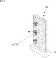
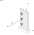
- FIG. 14 illustrates an example in which a second radiation region 147 of the aerosol-forming substrate 151 is carbonized more than a first radiation region 146 thereof.
- a typical aerosol-forming substrate 151 such as a tobacco material changes color as it is carbonized. Also, when the color changes, since characteristics of laser beams 148 and 149 reflected from the first radiation region 146 and the second radiation region 147, respectively, also change (e.g., the amount of reflected laser changes), the degree of carbonization of the corresponding regions 146 and 147 may be determined on the basis of the characteristics of the reflected laser beams 148 and 149 (e.g., the amount of reflected laser).
- heating control may be performed on the basis of a result of the determination.
- a specific heating control method may vary.
- a site irradiated with the laser may be controlled on the basis of a result of the determination.
- the controller 120 may change the current radiation region to another region (e.g., to a non-carbonized region).
- the controller 120 may move the laser radiation part 140 and/or the aerosol-generating article 150 to change the current radiation region.
- the controller 120 may irradiate one or more candidate regions with laser and determine a degree of carbonization of each candidate region on the basis of the laser reflected from each candidate region and may change the current radiation region to a candidate region whose degree of carbonization is less than the reference value.
- the controller 120 may change the current radiation region to a random point.
- the controller 120 may change the current radiation region to a subsequent region.
- the radiation region of the laser may be adjusted on the basis of a result of the determination.
- the description given above with reference to FIG. 12 may be referenced.
- the radiation intensity of the laser may be controlled on the basis of a result of the determination. For example, in a case in which the current radiation region of the aerosol-forming substrate 151 is determined as having been carbonized to a reference value or more, the controller 120 may decrease the radiation intensity of the laser. In the opposite case, the controller 120 may increase the radiation intensity of the laser.
- a movement speed of the laser radiation part 140 and/or the aerosol-generating article 150 may be controlled on the basis of a result of the determination. For example, in a case in which the current radiation region of the aerosol-forming substrate 151 is determined as having been carbonized to a reference value or more, the controller 120 may increase the movement speed of the laser radiation part 140 and/or the aerosol-generating article 150. In the opposite case, the controller 120 may decrease the movement speed.
- the technical spirit of the present disclosure or the technical spirit related to the operation of the controller 120 described above with reference to FIGS. 12 to 14 may be implemented with computer-readable code on computer-readable recording media.
- Examples of the computer-readable recording media may include removable recording media (a compact disc (CD), a digital versatile disc (DVD), a Blu-Ray disk, a Universal Serial Bus (USB) storage device, or a removable hard disk) or non-removable recording media (a read-only memory (ROM), a random access memory (RAM), or a built-in hard disk).
- Computer programs recorded in the computer-readable recording media may be sent to other computing devices through a network, such as the Internet, and installed on the other computing devices to be used in the other computing devices.
Landscapes
- Physics & Mathematics (AREA)
- Electromagnetism (AREA)
- Engineering & Computer Science (AREA)
- Plasma & Fusion (AREA)
- Optics & Photonics (AREA)
- Laser Beam Processing (AREA)
- Resistance Heating (AREA)
Applications Claiming Priority (2)
| Application Number | Priority Date | Filing Date | Title |
|---|---|---|---|
| KR1020210040346A KR102513606B1 (ko) | 2021-03-29 | 2021-03-29 | 레이저 기반의 에어로졸 발생 장치 및 그의 가열 제어 방법 |
| PCT/KR2021/016507 WO2022211209A1 (fr) | 2021-03-29 | 2021-11-12 | Dispositif de génération d'aérosol par laser et procédé de commande de chauffage associé |
Publications (3)
| Publication Number | Publication Date |
|---|---|
| EP4133955A1 true EP4133955A1 (fr) | 2023-02-15 |
| EP4133955A4 EP4133955A4 (fr) | 2023-12-06 |
| EP4133955B1 EP4133955B1 (fr) | 2025-09-24 |
Family
ID=83456436
Family Applications (1)
| Application Number | Title | Priority Date | Filing Date |
|---|---|---|---|
| EP21935322.4A Active EP4133955B1 (fr) | 2021-03-29 | 2021-11-12 | Dispositif de génération d'aérosol par laser et procédé de commande de chauffage associé |
Country Status (6)
| Country | Link |
|---|---|
| US (1) | US20230172272A1 (fr) |
| EP (1) | EP4133955B1 (fr) |
| JP (1) | JP7495026B2 (fr) |
| KR (1) | KR102513606B1 (fr) |
| CN (1) | CN115515445B (fr) |
| WO (1) | WO2022211209A1 (fr) |
Cited By (1)
| Publication number | Priority date | Publication date | Assignee | Title |
|---|---|---|---|---|
| WO2025073794A1 (fr) * | 2023-10-06 | 2025-04-10 | Jt International Sa | Dispositif de génération d'aérosol |
Families Citing this family (12)
| Publication number | Priority date | Publication date | Assignee | Title |
|---|---|---|---|---|
| KR102533113B1 (ko) * | 2021-04-16 | 2023-05-15 | 주식회사 케이티앤지 | 레이저 기반의 에어로졸 발생 장치 및 그의 가열 제어 방법 |
| CN118104868A (zh) * | 2022-11-30 | 2024-05-31 | 深圳麦时科技有限公司 | 气溶胶生成装置 |
| CN118216706A (zh) * | 2022-12-19 | 2024-06-21 | 思摩尔国际控股有限公司 | 气溶胶生成装置 |
| CN116243181A (zh) * | 2023-03-16 | 2023-06-09 | 北京海博思创科技股份有限公司 | 锂离子电池热失控实验系统 |
| CN119014613A (zh) * | 2023-05-25 | 2024-11-26 | 思摩尔国际控股有限公司 | 加热不燃烧装置及其控制方法 |
| CN119214358A (zh) * | 2023-06-29 | 2024-12-31 | 思摩尔国际控股有限公司 | 一种气溶胶生成介质以及气溶胶生成装置 |
| CN119257307A (zh) * | 2023-07-04 | 2025-01-07 | 思摩尔国际控股有限公司 | 气溶胶生成基质、气溶胶生成制品以及电子雾化装置 |
| CN119488175A (zh) * | 2023-08-18 | 2025-02-21 | 深圳麦时科技有限公司 | 一种气溶胶生成装置及气溶胶生成系统 |
| WO2025098715A1 (fr) * | 2023-11-09 | 2025-05-15 | Jt International Sa | Dispositif de génération d'aérosol |
| CN120021798A (zh) * | 2023-11-21 | 2025-05-23 | 深圳市合元科技有限公司 | 加热装置、气溶胶生成系统及用于加热装置的光加热器 |
| CN121220787A (zh) * | 2024-06-27 | 2025-12-30 | 思摩尔国际控股有限公司 | 气溶胶生成系统及气溶胶产生装置 |
| CN121621606A (zh) * | 2024-08-30 | 2026-03-10 | 思摩尔国际控股有限公司 | 气溶胶生成装置 |
Family Cites Families (15)
| Publication number | Priority date | Publication date | Assignee | Title |
|---|---|---|---|---|
| US5934289A (en) * | 1996-10-22 | 1999-08-10 | Philip Morris Incorporated | Electronic smoking system |
| GB2400431B (en) * | 2003-03-18 | 2006-03-01 | Molins Plc | An ignition system for a smoking machine |
| JP6265365B2 (ja) * | 2013-05-09 | 2018-01-24 | 国立大学法人 東京大学 | 計測システム |
| CA2977246C (fr) * | 2015-02-25 | 2019-08-27 | Robert Schneider | Appareil portatif pour vaporisation de composes a base de plantes ou synthetiques par laser |
| GB201508405D0 (en) | 2015-05-15 | 2015-07-01 | British American Tobacco Co | Article and apparatus for generating an aerosol |
| GB201607474D0 (en) * | 2016-04-29 | 2016-06-15 | British American Tobacco Co | Article, apparatus and method of heating a smokable material |
| GB201607475D0 (en) * | 2016-04-29 | 2016-06-15 | British American Tobacco Co | Article for generating an inhalable medium and method of heating a smokable material |
| CN205794814U (zh) * | 2016-07-20 | 2016-12-14 | 湖北中烟工业有限责任公司 | 一种激光热源雾化的电子烟 |
| US10561175B2 (en) * | 2017-08-22 | 2020-02-18 | Healthier Choices Management Corp. | Electronic vaporizer with laser heat source |
| CN111511231A (zh) * | 2018-01-12 | 2020-08-07 | 菲利普莫里斯生产公司 | 包括等离子体加热元件的气溶胶生成装置 |
| WO2019138045A1 (fr) * | 2018-01-12 | 2019-07-18 | Philip Morris Products S.A. | Dispositif de génération d'aérosol comprenant un élément chauffant allongé |
| JP7176003B2 (ja) * | 2018-06-26 | 2022-11-21 | ジェイティー インターナショナル エス.エイ. | 光学式気化システムを有する電子タバコ |
| KR20210024490A (ko) * | 2018-06-26 | 2021-03-05 | 제이티 인터내셔널 소시에떼 아노님 | 광학 기화 시스템을 갖는 전자 궐련에서의 사용을 위한 무화기 |
| GB201812505D0 (en) * | 2018-07-31 | 2018-09-12 | Nicoventures Holdings Ltd | Aerosol generation |
| WO2020252450A1 (fr) * | 2019-06-13 | 2020-12-17 | Lumenary Inc. | Vaporisateur laser à chambre sèche |
-
2021
- 2021-03-29 KR KR1020210040346A patent/KR102513606B1/ko active Active
- 2021-11-12 US US17/925,681 patent/US20230172272A1/en active Pending
- 2021-11-12 EP EP21935322.4A patent/EP4133955B1/fr active Active
- 2021-11-12 JP JP2022562290A patent/JP7495026B2/ja active Active
- 2021-11-12 CN CN202180034075.XA patent/CN115515445B/zh active Active
- 2021-11-12 WO PCT/KR2021/016507 patent/WO2022211209A1/fr not_active Ceased
Cited By (1)
| Publication number | Priority date | Publication date | Assignee | Title |
|---|---|---|---|---|
| WO2025073794A1 (fr) * | 2023-10-06 | 2025-04-10 | Jt International Sa | Dispositif de génération d'aérosol |
Also Published As
| Publication number | Publication date |
|---|---|
| CN115515445A (zh) | 2022-12-23 |
| KR102513606B1 (ko) | 2023-03-23 |
| KR20220134978A (ko) | 2022-10-06 |
| JP7495026B2 (ja) | 2024-06-04 |
| EP4133955A4 (fr) | 2023-12-06 |
| CN115515445B (zh) | 2025-11-04 |
| US20230172272A1 (en) | 2023-06-08 |
| EP4133955B1 (fr) | 2025-09-24 |
| JP2023523901A (ja) | 2023-06-08 |
| WO2022211209A1 (fr) | 2022-10-06 |
Similar Documents
| Publication | Publication Date | Title |
|---|---|---|
| EP4133955B1 (fr) | Dispositif de génération d'aérosol par laser et procédé de commande de chauffage associé | |
| EP4226786A1 (fr) | Dispositif de génération d'aérosol par laser et procédé de commande de chauffage associé | |
| CN114901094B (zh) | 气溶胶生成装置及其控制方法、以及计算机可读记录介质 | |
| JP7291785B2 (ja) | エアロゾル生成装置及びその動作方法 | |
| US11707089B2 (en) | Smoking device | |
| RU2700965C1 (ru) | Элемент, устройство и способ нагревания курительного материала | |
| JP7299321B2 (ja) | 温湿度に基づいてエアロゾル生成装置のヒータの温度を制御する方法及びその装置 | |
| KR102455534B1 (ko) | 에어로졸 생성 장치 및 에어로졸 생성 시스템 | |
| CN105473011A (zh) | 用于电子烟的发热预测及通信 | |
| KR20240003609A (ko) | 에어로졸 발생 장치 | |
| KR20210128111A (ko) | 에어로졸 발생 장치 및 그의 제어 방법 | |
| KR20220012004A (ko) | 에어로졸 발생 장치 및 그의 히터 제어 방법 | |
| US20250160435A1 (en) | Aerosol generating device using capacitive touch sensing | |
| KR102690637B1 (ko) | 에어로졸 발생 물품 및 에어로졸 발생 시스템 | |
| KR20240027720A (ko) | 에어로졸 발생 장치 | |
| WO2025132014A1 (fr) | Dispositif de génération d'aérosol à source de rayonnement électromagnétique et capteur | |
| KR20240041493A (ko) | 에어로졸 발생 장치 및 에어로졸 발생 물품 | |
| KR20260004069A (ko) | 에어로졸 생성 장치 | |
| KR20260024166A (ko) | 카트리지 및 이를 포함하는 에어로졸 생성 장치 | |
| KR20240088806A (ko) | Led를 포함하는 에어로졸 생성 디바이스 |
Legal Events
| Date | Code | Title | Description |
|---|---|---|---|
| STAA | Information on the status of an ep patent application or granted ep patent |
Free format text: STATUS: THE INTERNATIONAL PUBLICATION HAS BEEN MADE |
|
| PUAI | Public reference made under article 153(3) epc to a published international application that has entered the european phase |
Free format text: ORIGINAL CODE: 0009012 |
|
| STAA | Information on the status of an ep patent application or granted ep patent |
Free format text: STATUS: REQUEST FOR EXAMINATION WAS MADE |
|
| 17P | Request for examination filed |
Effective date: 20221110 |
|
| AK | Designated contracting states |
Kind code of ref document: A1 Designated state(s): AL AT BE BG CH CY CZ DE DK EE ES FI FR GB GR HR HU IE IS IT LI LT LU LV MC MK MT NL NO PL PT RO RS SE SI SK SM TR |
|
| P01 | Opt-out of the competence of the unified patent court (upc) registered |
Effective date: 20230526 |
|
| A4 | Supplementary search report drawn up and despatched |
Effective date: 20231106 |
|
| RIC1 | Information provided on ipc code assigned before grant |
Ipc: H01S 3/00 20060101ALI20231030BHEP Ipc: H05B 35/00 20060101ALI20231030BHEP Ipc: A24F 40/50 20200101ALI20231030BHEP Ipc: A24F 7/00 20060101ALI20231030BHEP Ipc: A24F 40/46 20200101AFI20231030BHEP |
|
| DAV | Request for validation of the european patent (deleted) | ||
| DAX | Request for extension of the european patent (deleted) | ||
| GRAP | Despatch of communication of intention to grant a patent |
Free format text: ORIGINAL CODE: EPIDOSNIGR1 |
|
| STAA | Information on the status of an ep patent application or granted ep patent |
Free format text: STATUS: GRANT OF PATENT IS INTENDED |
|
| RIC1 | Information provided on ipc code assigned before grant |
Ipc: A24F 40/20 20200101ALN20250430BHEP Ipc: A24F 40/50 20200101ALI20250430BHEP Ipc: A24F 40/46 20200101AFI20250430BHEP |
|
| INTG | Intention to grant announced |
Effective date: 20250509 |
|
| GRAS | Grant fee paid |
Free format text: ORIGINAL CODE: EPIDOSNIGR3 |
|
| GRAA | (expected) grant |
Free format text: ORIGINAL CODE: 0009210 |
|
| STAA | Information on the status of an ep patent application or granted ep patent |
Free format text: STATUS: THE PATENT HAS BEEN GRANTED |
|
| AK | Designated contracting states |
Kind code of ref document: B1 Designated state(s): AL AT BE BG CH CY CZ DE DK EE ES FI FR GB GR HR HU IE IS IT LI LT LU LV MC MK MT NL NO PL PT RO RS SE SI SK SM TR |
|
| REG | Reference to a national code |
Ref country code: GB Ref legal event code: FG4D |
|
| REG | Reference to a national code |
Ref country code: CH Ref legal event code: EP |
|
| REG | Reference to a national code |
Ref country code: DE Ref legal event code: R096 Ref document number: 602021039343 Country of ref document: DE |
|
| REG | Reference to a national code |
Ref country code: IE Ref legal event code: FG4D |
|
| PGFP | Annual fee paid to national office [announced via postgrant information from national office to epo] |
Ref country code: DE Payment date: 20251029 Year of fee payment: 5 |
|
| PGFP | Annual fee paid to national office [announced via postgrant information from national office to epo] |
Ref country code: GB Payment date: 20251023 Year of fee payment: 5 |
|
| PG25 | Lapsed in a contracting state [announced via postgrant information from national office to epo] |
Ref country code: NO Free format text: LAPSE BECAUSE OF FAILURE TO SUBMIT A TRANSLATION OF THE DESCRIPTION OR TO PAY THE FEE WITHIN THE PRESCRIBED TIME-LIMIT Effective date: 20251224 |
|
| REG | Reference to a national code |
Ref country code: LT Ref legal event code: MG9D |
|
| PGFP | Annual fee paid to national office [announced via postgrant information from national office to epo] |
Ref country code: AT Payment date: 20260113 Year of fee payment: 5 |
|
| PG25 | Lapsed in a contracting state [announced via postgrant information from national office to epo] |
Ref country code: FI Free format text: LAPSE BECAUSE OF FAILURE TO SUBMIT A TRANSLATION OF THE DESCRIPTION OR TO PAY THE FEE WITHIN THE PRESCRIBED TIME-LIMIT Effective date: 20250924 |
|
| PGFP | Annual fee paid to national office [announced via postgrant information from national office to epo] |
Ref country code: IT Payment date: 20251127 Year of fee payment: 5 |
|
| PG25 | Lapsed in a contracting state [announced via postgrant information from national office to epo] |
Ref country code: HR Free format text: LAPSE BECAUSE OF FAILURE TO SUBMIT A TRANSLATION OF THE DESCRIPTION OR TO PAY THE FEE WITHIN THE PRESCRIBED TIME-LIMIT Effective date: 20250924 |
|
| PGFP | Annual fee paid to national office [announced via postgrant information from national office to epo] |
Ref country code: FR Payment date: 20251023 Year of fee payment: 5 |
|
| PG25 | Lapsed in a contracting state [announced via postgrant information from national office to epo] |
Ref country code: GR Free format text: LAPSE BECAUSE OF FAILURE TO SUBMIT A TRANSLATION OF THE DESCRIPTION OR TO PAY THE FEE WITHIN THE PRESCRIBED TIME-LIMIT Effective date: 20251225 |
|
| PG25 | Lapsed in a contracting state [announced via postgrant information from national office to epo] |
Ref country code: SE Free format text: LAPSE BECAUSE OF FAILURE TO SUBMIT A TRANSLATION OF THE DESCRIPTION OR TO PAY THE FEE WITHIN THE PRESCRIBED TIME-LIMIT Effective date: 20250924 |
|
| PG25 | Lapsed in a contracting state [announced via postgrant information from national office to epo] |
Ref country code: LV Free format text: LAPSE BECAUSE OF FAILURE TO SUBMIT A TRANSLATION OF THE DESCRIPTION OR TO PAY THE FEE WITHIN THE PRESCRIBED TIME-LIMIT Effective date: 20250924 |
|
| PG25 | Lapsed in a contracting state [announced via postgrant information from national office to epo] |
Ref country code: BG Free format text: LAPSE BECAUSE OF FAILURE TO SUBMIT A TRANSLATION OF THE DESCRIPTION OR TO PAY THE FEE WITHIN THE PRESCRIBED TIME-LIMIT Effective date: 20250924 |
|
| PG25 | Lapsed in a contracting state [announced via postgrant information from national office to epo] |
Ref country code: RS Free format text: LAPSE BECAUSE OF FAILURE TO SUBMIT A TRANSLATION OF THE DESCRIPTION OR TO PAY THE FEE WITHIN THE PRESCRIBED TIME-LIMIT Effective date: 20251224 |
|
| REG | Reference to a national code |
Ref country code: NL Ref legal event code: MP Effective date: 20250924 |
|
| PG25 | Lapsed in a contracting state [announced via postgrant information from national office to epo] |
Ref country code: NL Free format text: LAPSE BECAUSE OF FAILURE TO SUBMIT A TRANSLATION OF THE DESCRIPTION OR TO PAY THE FEE WITHIN THE PRESCRIBED TIME-LIMIT Effective date: 20250924 |
|
| REG | Reference to a national code |
Ref country code: AT Ref legal event code: MK05 Ref document number: 1839668 Country of ref document: AT Kind code of ref document: T Effective date: 20250924 |
|
| PG25 | Lapsed in a contracting state [announced via postgrant information from national office to epo] |
Ref country code: SM Free format text: LAPSE BECAUSE OF FAILURE TO SUBMIT A TRANSLATION OF THE DESCRIPTION OR TO PAY THE FEE WITHIN THE PRESCRIBED TIME-LIMIT Effective date: 20250924 |
|
| PG25 | Lapsed in a contracting state [announced via postgrant information from national office to epo] |
Ref country code: ES Free format text: LAPSE BECAUSE OF FAILURE TO SUBMIT A TRANSLATION OF THE DESCRIPTION OR TO PAY THE FEE WITHIN THE PRESCRIBED TIME-LIMIT Effective date: 20250924 |
|
| PG25 | Lapsed in a contracting state [announced via postgrant information from national office to epo] |
Ref country code: AT Free format text: LAPSE BECAUSE OF FAILURE TO SUBMIT A TRANSLATION OF THE DESCRIPTION OR TO PAY THE FEE WITHIN THE PRESCRIBED TIME-LIMIT Effective date: 20250924 |
|
| PG25 | Lapsed in a contracting state [announced via postgrant information from national office to epo] |
Ref country code: RO Free format text: LAPSE BECAUSE OF FAILURE TO SUBMIT A TRANSLATION OF THE DESCRIPTION OR TO PAY THE FEE WITHIN THE PRESCRIBED TIME-LIMIT Effective date: 20250924 |
|
| PG25 | Lapsed in a contracting state [announced via postgrant information from national office to epo] |
Ref country code: IS Free format text: LAPSE BECAUSE OF FAILURE TO SUBMIT A TRANSLATION OF THE DESCRIPTION OR TO PAY THE FEE WITHIN THE PRESCRIBED TIME-LIMIT Effective date: 20260124 |
|
| PG25 | Lapsed in a contracting state [announced via postgrant information from national office to epo] |
Ref country code: CZ Free format text: LAPSE BECAUSE OF FAILURE TO SUBMIT A TRANSLATION OF THE DESCRIPTION OR TO PAY THE FEE WITHIN THE PRESCRIBED TIME-LIMIT Effective date: 20250924 Ref country code: PT Free format text: LAPSE BECAUSE OF FAILURE TO SUBMIT A TRANSLATION OF THE DESCRIPTION OR TO PAY THE FEE WITHIN THE PRESCRIBED TIME-LIMIT Effective date: 20260126 |
|
| PG25 | Lapsed in a contracting state [announced via postgrant information from national office to epo] |
Ref country code: PL Free format text: LAPSE BECAUSE OF FAILURE TO SUBMIT A TRANSLATION OF THE DESCRIPTION OR TO PAY THE FEE WITHIN THE PRESCRIBED TIME-LIMIT Effective date: 20250924 |
|
| PG25 | Lapsed in a contracting state [announced via postgrant information from national office to epo] |
Ref country code: EE Free format text: LAPSE BECAUSE OF FAILURE TO SUBMIT A TRANSLATION OF THE DESCRIPTION OR TO PAY THE FEE WITHIN THE PRESCRIBED TIME-LIMIT Effective date: 20250924 Ref country code: SK Free format text: LAPSE BECAUSE OF FAILURE TO SUBMIT A TRANSLATION OF THE DESCRIPTION OR TO PAY THE FEE WITHIN THE PRESCRIBED TIME-LIMIT Effective date: 20250924 |