EP4134007B1 - Abtastvorrichtung sowie verfahren - Google Patents
Abtastvorrichtung sowie verfahren Download PDFInfo
- Publication number
- EP4134007B1 EP4134007B1 EP21802999.9A EP21802999A EP4134007B1 EP 4134007 B1 EP4134007 B1 EP 4134007B1 EP 21802999 A EP21802999 A EP 21802999A EP 4134007 B1 EP4134007 B1 EP 4134007B1
- Authority
- EP
- European Patent Office
- Prior art keywords
- detector
- radiation source
- arm
- arm section
- scanning
- Prior art date
- Legal status (The legal status is an assumption and is not a legal conclusion. Google has not performed a legal analysis and makes no representation as to the accuracy of the status listed.)
- Active
Links
Images





Classifications
-
- A—HUMAN NECESSITIES
- A61—MEDICAL OR VETERINARY SCIENCE; HYGIENE
- A61B—DIAGNOSIS; SURGERY; IDENTIFICATION
- A61B6/00—Apparatus or devices for radiation diagnosis; Apparatus or devices for radiation diagnosis combined with radiation therapy equipment
- A61B6/54—Control of apparatus or devices for radiation diagnosis
-
- A—HUMAN NECESSITIES
- A61—MEDICAL OR VETERINARY SCIENCE; HYGIENE
- A61B—DIAGNOSIS; SURGERY; IDENTIFICATION
- A61B6/00—Apparatus or devices for radiation diagnosis; Apparatus or devices for radiation diagnosis combined with radiation therapy equipment
- A61B6/02—Arrangements for diagnosis sequentially in different planes; Stereoscopic radiation diagnosis
- A61B6/027—Arrangements for diagnosis sequentially in different planes; Stereoscopic radiation diagnosis characterised by the use of a particular data acquisition trajectory, e.g. helical or spiral
-
- A—HUMAN NECESSITIES
- A61—MEDICAL OR VETERINARY SCIENCE; HYGIENE
- A61B—DIAGNOSIS; SURGERY; IDENTIFICATION
- A61B6/00—Apparatus or devices for radiation diagnosis; Apparatus or devices for radiation diagnosis combined with radiation therapy equipment
- A61B6/02—Arrangements for diagnosis sequentially in different planes; Stereoscopic radiation diagnosis
- A61B6/03—Computed tomography [CT]
- A61B6/032—Transmission computed tomography [CT]
-
- A—HUMAN NECESSITIES
- A61—MEDICAL OR VETERINARY SCIENCE; HYGIENE
- A61B—DIAGNOSIS; SURGERY; IDENTIFICATION
- A61B6/00—Apparatus or devices for radiation diagnosis; Apparatus or devices for radiation diagnosis combined with radiation therapy equipment
- A61B6/02—Arrangements for diagnosis sequentially in different planes; Stereoscopic radiation diagnosis
- A61B6/03—Computed tomography [CT]
- A61B6/032—Transmission computed tomography [CT]
- A61B6/035—Mechanical aspects of CT
-
- A—HUMAN NECESSITIES
- A61—MEDICAL OR VETERINARY SCIENCE; HYGIENE
- A61B—DIAGNOSIS; SURGERY; IDENTIFICATION
- A61B6/00—Apparatus or devices for radiation diagnosis; Apparatus or devices for radiation diagnosis combined with radiation therapy equipment
- A61B6/40—Arrangements for generating radiation specially adapted for radiation diagnosis
- A61B6/4064—Arrangements for generating radiation specially adapted for radiation diagnosis specially adapted for producing a particular type of beam
- A61B6/4085—Cone-beams
-
- A—HUMAN NECESSITIES
- A61—MEDICAL OR VETERINARY SCIENCE; HYGIENE
- A61B—DIAGNOSIS; SURGERY; IDENTIFICATION
- A61B6/00—Apparatus or devices for radiation diagnosis; Apparatus or devices for radiation diagnosis combined with radiation therapy equipment
- A61B6/44—Constructional features of apparatus for radiation diagnosis
- A61B6/4429—Constructional features of apparatus for radiation diagnosis related to the mounting of source units and detector units
- A61B6/4435—Constructional features of apparatus for radiation diagnosis related to the mounting of source units and detector units the source unit and the detector unit being coupled by a rigid structure
- A61B6/4441—Constructional features of apparatus for radiation diagnosis related to the mounting of source units and detector units the source unit and the detector unit being coupled by a rigid structure the rigid structure being a C-arm or U-arm
-
- A—HUMAN NECESSITIES
- A61—MEDICAL OR VETERINARY SCIENCE; HYGIENE
- A61B—DIAGNOSIS; SURGERY; IDENTIFICATION
- A61B6/00—Apparatus or devices for radiation diagnosis; Apparatus or devices for radiation diagnosis combined with radiation therapy equipment
- A61B6/44—Constructional features of apparatus for radiation diagnosis
- A61B6/4429—Constructional features of apparatus for radiation diagnosis related to the mounting of source units and detector units
- A61B6/4435—Constructional features of apparatus for radiation diagnosis related to the mounting of source units and detector units the source unit and the detector unit being coupled by a rigid structure
- A61B6/4447—Tiltable gantries
-
- A—HUMAN NECESSITIES
- A61—MEDICAL OR VETERINARY SCIENCE; HYGIENE
- A61B—DIAGNOSIS; SURGERY; IDENTIFICATION
- A61B6/00—Apparatus or devices for radiation diagnosis; Apparatus or devices for radiation diagnosis combined with radiation therapy equipment
- A61B6/44—Constructional features of apparatus for radiation diagnosis
- A61B6/4429—Constructional features of apparatus for radiation diagnosis related to the mounting of source units and detector units
- A61B6/4458—Constructional features of apparatus for radiation diagnosis related to the mounting of source units and detector units the source unit or the detector unit being attached to robotic arms
-
- A—HUMAN NECESSITIES
- A61—MEDICAL OR VETERINARY SCIENCE; HYGIENE
- A61B—DIAGNOSIS; SURGERY; IDENTIFICATION
- A61B6/00—Apparatus or devices for radiation diagnosis; Apparatus or devices for radiation diagnosis combined with radiation therapy equipment
- A61B6/44—Constructional features of apparatus for radiation diagnosis
- A61B6/4476—Constructional features of apparatus for radiation diagnosis related to motor-assisted motion of the source unit
-
- A—HUMAN NECESSITIES
- A61—MEDICAL OR VETERINARY SCIENCE; HYGIENE
- A61B—DIAGNOSIS; SURGERY; IDENTIFICATION
- A61B6/00—Apparatus or devices for radiation diagnosis; Apparatus or devices for radiation diagnosis combined with radiation therapy equipment
- A61B6/52—Devices using data or image processing specially adapted for radiation diagnosis
- A61B6/5205—Devices using data or image processing specially adapted for radiation diagnosis involving processing of raw data to produce diagnostic data
-
- A—HUMAN NECESSITIES
- A61—MEDICAL OR VETERINARY SCIENCE; HYGIENE
- A61B—DIAGNOSIS; SURGERY; IDENTIFICATION
- A61B6/00—Apparatus or devices for radiation diagnosis; Apparatus or devices for radiation diagnosis combined with radiation therapy equipment
- A61B6/44—Constructional features of apparatus for radiation diagnosis
- A61B6/4429—Constructional features of apparatus for radiation diagnosis related to the mounting of source units and detector units
- A61B6/4464—Constructional features of apparatus for radiation diagnosis related to the mounting of source units and detector units the source unit or the detector unit being mounted to ceiling
Definitions
- An X-ray device is a device that can be used to examine and diagnose various parts of an object.
- a device that uses X-rays as the basis for the examination and diagnosis, and controls the X-rays to perform a radiological examination and a radiotherapy on a human tissue can help doctors to determine a patient's specific condition.
- the X-ray device may include a mammography X-ray device, a dental (oral) X-ray device, a digital subtraction angiography (DSA) X-ray device, etc.
- DSA digital subtraction angiography
- An operator usually adjusts a detector and a radiation source through a lift assembly of the C-shaped arm to meet imaging requirements of different scenes. An overall size of the lift assembly has a great influence on the operation of the C-shaped arm (or the C-shaped main body part).
- the method is implemented by a cone-beam computed tomography scanning apparatus.
- the cone-beam computed tomography scanning apparatus includes a radiation source and a detector.
- the method includes: deflecting the radiation source and the detector around a center point of the detector; and rotating the deflected radiation source and the deflected detector around a center of interest of a target object to scan the target object and obtain scanning data of the target object.
- the radiation source and the detector have a first reconstruction FOV before the deflection, the radiation source and the detector have a second reconstruction FOV after the deflection, and the second reconstruction FOV is larger than the first reconstruction FOV.
- the system is configured to control a cone-beam computed tomography scanning apparatus.
- the cone-beam computed tomography scanning apparatus including a radiation source and a detector.
- the system includes a deflection module configured to deflect the radiation source and the detector around a center point of the detector, and a rotation module configured to rotate the deflected radiation source and the deflected detector around a center of interest of the target object to scan the target object and obtain scanning data of the target object.
- the radiation source and the detector have a first reconstruction FOV before the deflection, the radiation source and the detector have a second reconstruction FOV after the deflection, and the second reconstruction FOV is larger than the first reconstruction FOV.
- the device includes at least one processor and at least one storage device, the storage device is configured to store an instruction, and when the at least one processor executes the instruction, the processor implements the method for obtaining the medical image described in the present disclosure.
- One of the embodiments of the present disclosure provides a cone-beam computed tomography scanner, including a robotic arm, a radiation source, and a detector.
- the robotic arm has a deflection mode and a rotation mode.
- the deflection mode the mechanical arm drives the radiation source and the detector to deflect around a center point of the detector.
- the rotation mode the robotic arm drives the deflected radiation source and the deflected detector to rotate around a center of interest of the target object to scan the target object and obtain scanning data of the target object.
- the radiation source and the detector have a first reconstruction FOV before the deflection, the radiation source and the detector have a second reconstruction FOV after the deflection, and the second reconstruction FOV is larger than the first reconstruction FOV.
- the lift assembly includes a shell, a driving assembly accommodated in the shell, and an arm adjustment assembly.
- the arm adjustment assembly moves under a driving of the driving assembly.
- the arm adjustment assembly includes an intermediate arm section, a target arm section, and a linkage assembly disposed between the intermediate arm section and the target arm section.
- the intermediate arm section can move in a first direction under the driving of the driving assembly.
- the target arm section can be driven to move in the first direction by the linkage assembly. Projections of the intermediate arm section and the target arm section respectively in the first direction at least partially overlap.
- the target arm section is connected to a detector or a radiation source.
- SID indicates a distance from the radiation source G to the detector EF.
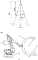
- FIG. 1 is a schematic diagram illustrating an application scenario of a medical image obtaining system according to some embodiments of the present disclosure.
- the medical image obtaining system may obtain scanning data of a target object based on an obtaining method disclosed in the present disclosure.
- the scanning apparatus 110 may include a gantry, a radiation source 112, a detector 113, a deflection mechanism (not shown in the figure) and a rotation mechanism (not shown in the figure).
- the gantry may include a supporting part 111 and a robotic arm 114.
- the robotic arm 114 may be connected to the supporting part 111 to drive the supporting part 111 to move.
- the supporting part 111 may support the radiation source 112 and the detector 113.
- the supporting part 111 may be a C-shaped arm as shown in FIG. 1 , or may be a U-shaped arm, a G-shaped arm, etc.
- the robotic arm 114 may drive the radiation source 112 and the detector 113 to rotate together, e.g., rotate clockwise or counterclockwise around the center of interest of a target object.
- the radiation source 112 and the detector 113 may be arranged opposite to each other, and a space between the radiation source 112 and the detector 113 may include an accommodating space of the target object.
- the radiation source 112 may emit a radiation beam to the target object, and the target object may be placed in the space between the radiation source 112 and the detector 113 to be scanned.
- the detector 113 may detect the radiation beam (e.g., an X-ray) emitted from the radiation source 112.
- the detector 113 may convert the passing radiation beam into a visible light. Then the visible light may be converted into an electrical signal through photoelectric conversion, and then be converted into digital information by an analog/digital converter, which may be input to a computing device (e.g., a computer) for processing, or be transmitted to the storage device 150 for storage.
- the detector 113 may include one or more detector units.
- the detector unit may include a scintillation detector (e.g., a cesium iodide detector) and other detectors, etc.
- the deflection mechanism may be used to deflect the radiation source 112 and the detector 113 as a whole around a center point of the detector 113.
- the processing device 140 may process data and/or information obtained from the scanning apparatus 110, the terminal 130, and/or the storage device 150. For example, the processing device 140 may perform a weighting process on a part of the scanning data (e.g., the scanning data of an area that is repeatedly scanned) to determine data required for image reconstruction. As another example, the processing device 140 may perform a data pre-processing, an image reconstruction, a reconstruction post-processing, etc., on the scanning data. In some embodiments, the processing device 140 may further control a scanning action of the scanning apparatus 110. For example, the processing device 140 may control the radiation source 112 and the detector 113 to deflect a specific angle around the center point of the detector 113.
- the processing device 140 may control the radiation source 112 and the detector 113 to rotate and scan around the center of interest of the target object.
- the processing device 140 may include a single server or a server group. The server group may be centralized or distributed. In some embodiments, the processing device 140 may be local or remote.
- the processing device 140 may access information and/or data from the scanning apparatus 110, the terminal 130, and/or the storage device 150 via the network 120.
- the processing device 140 may be directly connected to the scanning apparatus 110, the terminal 130, and/or the storage device 150 to access information and/or data.
- the processing device 140 may be implemented in a cloud platform.
- the cloud platform may include a private cloud, a public cloud, a hybrid cloud, a community cloud, a distributed cloud, an inter-cloud, a multi-cloud, or the like, or any combination thereof.
- the storage device 150 may store data (e.g., the scanning data of the target object, etc.), an instruction, and/or any other information.
- the storage device 150 may store data obtained from the scanning apparatus 110, the terminal 130, and/or the processing device 140.
- the storage device 150 may store the scanning data of the target object obtained from the scanning apparatus 110.
- the storage device 150 may store data and/or instructions performed or used by the processing device 140 to perform the exemplary methods of the present disclosure.
- the storage device 150 may store data obtained by weighting the scanning data of the repeatedly scanned area.
- the storage device 150 may further store image data obtained in real-time and/or image data obtained during and/or after reconstruction.
- FIG. 2 is a flowchart illustrating an exemplary medical image obtaining method according to some embodiments of the present disclosure.
- a process 200 may be performed by a processing logic, including a hardware (e.g., a circuit, a dedicated logic, a programmable logic, a microcode, etc.), a software (an instruction run on a processing device to perform hardware simulation), etc., or any combination thereof.
- One or more operations in the process 200 for obtaining a medical image shown in FIG. 2 may be implemented by the processing device 140 shown in FIG. 1 .
- the process 200 may be stored in the storage device 150 in the form of an instruction and may be retrieved and/or executed by the processing device 140.
- a radiation source and a detector may be deflected around a center point of the detector.
- the operation 210 may be performed by a deflection module 510.
- the detector may receive the radiation beam (for example, the X-ray) passing through the target object, and convert it into a visible light.
- the visible light may be converted into an electrical signal through photoelectric conversion.
- the detector may convert the electrical signal into digital information by an analog/digital converter.
- the detector may include but be not limited to, a flat panel detector.
- the DSA scanner may be taken as an example to illustrate the medical image obtaining method and system.
- the target object may include a patient, other medical experimental objects (e.g., an animal such as an experimental mouse), organs and/or tissues (e.g., an arm, etc.) of a patient, a phantom, or other medical experimental objects, etc.
- the processing device 140 may rotate the deflected radiation source and the deflected detector around the center of interest of the target object to scan the target object.
- the rotation direction may be any direction centered on the center of interest of the target object. For example, a clockwise direction, a counterclockwise direction, etc.
- the rotation angle may include 10°, 15°, 90°, 180°, or 360°, etc.
- reconstructing the scanning data of the target object to obtain a reconstruction image of the target object may be performed by a reconstruction module 530.
- part of the target object may always be scanned, that is, the scanning data of part of the target object may be repeatedly scanned for twice or more.
- some areas may not be scanned again after the radiation source and the detector rotate more than 180° around the center of interest of the target object, while some areas may always be scanned during the 360° rotation of the radiation source and the detector around the center of interest of the target object.
- the area that can always be scanned may be referred to as a repeatedly scanned area.
- the scanning data of the repeatedly scanned area needs to be processed before reconstruction to obtain "de-duplicated" scanning data which can be used to reconstruct the reconstruction image with better image quality.
- the processing the scanning data may include weighting the scanning data based on a preset weight curve.
- the weighting may refer to multiplying the scanning data of the repeatedly scanned area by different weight coefficients to eliminate an influence of the scanning data of the repeatedly scanned area on the reconstruction image.
- the preset weight curve please refer to FIG. 4 and related descriptions, which are not repeated here.
- the scanning view of the single gantry after deflecting the radiation source and the detector may cover more than half of the second reconstruction FOV to ensure the acquisition of sufficient scanning data.
- the deflection angle is adjustable. In some embodiments, there may be different deflection angles according to different usage requirements. For example, when the volume of the target object is relatively large, the deflection angle may be increased accordingly. In some embodiments, the deflection angle may be in a range of 1° ⁇ 60°. For example, the deflection angle may include but be not limited to, 1°, 3°, 5°, 10°, 30°, 45°, 60°, etc.
- the deflection angle may be the smallest angle for the second reconstruction FOV to cover the target object. For example, when the minimum deflection angle required for the second reconstruction FOV to cover the target object (e.g., an abdomen) is 30°, the deflection angle may be set to 30°. By setting the deflection angle as the minimum angle for the second reconstruction FOV to cover the target object, an image reconstruction quality may be effectively improved under the condition of sufficient reconstruction area.
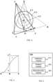
- FIG. 4 is a schematic diagram illustrating a preset weight curve according to some embodiments of the present disclosure.
- the repeatedly scanned area may be the area enclosed by circle C3 shown in FIG. 3 .
- a preset weight curve is related to positions at the detector corresponding to the repeatedly scanned area.
- positions at the detector corresponding to the repeatedly scanned area may include positions at the detector where scanning data of the repeatedly scanned area is collected.
- the positions at the detector corresponding to the repeatedly scanned area may be positions within the BN part of the detector shown in FIG. 3 .
- two tangent lines CB and CN tangent to the repeatedly scanned area (the circle C3) may be determined.
- a straight-line CO starting from the deflected radiation source C and passing through the center O of interest of the target object needs to be determined.
- the straight-line CO passes through a third point (point M) of the deflected detector AB.
- the first point (point B) may be located at an edge of the deflected detector AB
- the second point (point N) may be located in a non-edge area of the deflected detector AB
- the third point (point M) may be located between the first point (point B) and the second point (point N).
- the smooth curve passing through the first point (e.g., point B) and the third point (e.g., point M) may be of one type of curve distribution
- the smooth curve passing through the third point (e.g., point M) and the second point (e.g., point N) may be the other type of curve distribution
- the smooth curve passing through the first point (e.g., point B) and the third point (e.g., point M) may be a sine curve
- the smooth curve passing through the third point (e.g., point M) and the second point (e.g., point N) may be a logarithmic curve.
- the smooth curve passing through the first point (e.g., point B) and the third point (e.g., point M) may be a logarithmic curve
- the smooth curve passing through the third point (e.g., point M) and the second point (e.g., point N) may be a tangent curve.
- the present disclosure does not make any limitation on the type of the smooth curve.
- the abscissa indicates the position at the detector that collects the scanning data of the repeatedly scanned area, and the ordinate indicates a weight value.
- FIG. 5 is a block diagram illustrating a system for obtaining a medical image according to some embodiments of the present disclosure.
- the deflection module 510 and the rotation module 520 disclosed in FIG. 5 may be one module to implement the functions of the above two modules.
- the modules may share one storage module, or each module may further have its own storage module. Such deformations are all within the protection scope of the present disclosure.
- the robotic arm 114 may drive the radiation source 112 and the detector 113 to deflect around the center point of the detector 113.
- the center point of the detector 113 may refer to a geometric center point of the detector 113.
- its center point may refer to the geometric center point of the flat panel detector.
- the scanning apparatus 110 may include the cone-beam computed tomography scanning apparatus (CBCT).
- the cone-beam computed tomography device may include a gantry, a radiation source 112, and a detector 113.
- the gantry may include a supporting part 111.
- the supporting part 111 may be configured to support the radiation source 112 and the detector 113.
- a space between the radiation source 112 and the detector 113 may include an accommodation space for a target object.
- the radiation source 112 may be configured to emit X-rays that passes through the target object and are attenuated.
- the detector 113 may be set opposite to the radiation source 112.
- the detector 113 may receive the X-rays passing through the target object, convert the X-rays into a visible light, and convert the visible light into an electrical signal through photoelectric conversion.
- the electrical signal may be converted into digital information by an analog/digital converter.
- the beneficial effects of the medical image obtaining method and system according to the embodiments of the present disclosure may include but be not limited to: (1) a relatively large reconstruction FOV may be obtained with a certain size of the detector; (2) the "de-duplicated" scanning data may be obtained by weighting the scanning data of the repeatedly scanned area based on the obtained reconstruction FOV, which can be reconstructed to obtain an image with no artifact and better quality; (3) the scanning apparatus may have a compact structure, which is more convenient for a clinical operation.
- the radiation source 712 may be regarded as a device capable of emitting a ray (an X-ray, a ⁇ ray, or an electron ray, etc.), and the ray detector 711 may be regarded as a device capable of receiving the ray emitted by the radiation source 712.
- a ray an X-ray, a ⁇ ray, or an electron ray, etc.
- the ray detector 711 may be regarded as a device capable of receiving the ray emitted by the radiation source 712.
- a control code embodied in processor, for example, on a carrier medium such as a hard disk, a magnetic disk, a CD, or a DVD-ROM, or such code is provided on a programmable memory of a ROM (firmware) or a data carrier such as an optical or electronic signal carrier.
- the reciprocating spiral trajectory may be configured such that during the motion of the radiation source 712 in the first direction, the radiation source 712 first rotates clockwise by 270° or by other angles (such as 180°, 315°, 360°, etc.), and then rotates counterclockwise by 270° or by other angles (such as 180°, 315°, 360°, etc.). The process continues until the scan is completed.
- the clockwise rotation angle and the counterclockwise rotation angle may be the same or different.
- the radiation source 712 may first rotate 27° clockwise, and then rotate more than 270° counterclockwise (e.g., 360°, 540°, etc.).
- the radiation source 712 may further rotate counterclockwise first and then rotate clockwise.
- the first direction is perpendicular to a circumferential plane formed when the radiation source 712 has the circular motion.
- the circumferential plane formed when the radiation source 712 has the circular motion may be understood as a circumferential plane formed when the radiation source 712 only has the circular motion without moving in the first direction.
- the fact that the first direction is perpendicular to the aforementioned circumferential plane may facilitate the scan, enlarge a scanning space, and make it easier for the subsequent image reconstruction.
- the controller is configured to control the radiation source 712 to move in the first direction while performing a circular scanning motion within a scanning range.
- the scanning range covers a target scanning range.
- the radiation source 712 may be controlled by the controller to quickly move to a position within the scanning range (e.g., the starting area of the scanning range), and then the radiation source 712 may be controlled to perform the circular scanning motion in the scanning range while moving in the first direction.
- the scanning range may be understood as a space where the radiation source 712 and the ray detector 711 perform data collection, and the target scanning range may be understood as a lesion area of the scanned object. By using the scanning range that covers the target scanning range, an effective data collection may be achieved for the lesion area of the scanned object. By controlling the radiation source 712 to move rapidly in the non-scanning range, the scanning efficiency may be effectively improved.
- the scanning system described above may be a digital subtraction angiography (DSA) device.
- DSA digital subtraction angiography
- the DSA device is a kind of blood vessel examination device that combines a conventional angiography with a computer image processing technology, which can more clearly display the blood vessels and their lesions, and has a high application value.
- a detection cost may be greatly reduced, and difficulties in subsequent operations may be reduced to a certain extent.
- the aforementioned scanning system may further be applied to other scanning apparatuses, such as a peripheral interventional C-shaped arm, a C-shaped arm X-ray machine, etc.
- the beneficial effects of the scanning system 700 based on the C-shaped arm 710 disclosed in the present disclosure may include but be not limited to: (1) through the circular motion and the motion in the first direction, the information collection during the scanning process may be more complete; (2) the complete information collection may improve the image reconstruction effect and greatly reduce the generation of artifacts; (3) when controlling the C-shaped arm 710 to scan, the problem of cable entanglement may not occur; (4) the scanning system 700 is applicable for lesions in different locations; (5) by using the robot arm assembly 730 for driving, the movement may be precise and stable, and the degree of automation may be high.
- the lift assembly for adjusting the SID includes a lift arm connected to the detector or the radiation source and a supporting shell for supporting the motion of the lift arm.
- the lift arm may move in an adjustment direction relative to the supporting shell to drive the motion of the detector or the radiation source, thereby realizing the distance adjustment of the SID.
- the supporting shell needs to provide enough moving path length for the lift arm, that is, the length of the supporting shell along the adjustment direction needs to be greater than or equal to the moving path length of the lift arm (that is, the maximum adjustment distance of the SID). That is to say, if the moving path length of the lift arm is L, the length of the supporting shell is at least L.
- the linkage assembly includes a first support component 2351 and a second support component 2352 arranged on the intermediate arm section 1231, a first flexible traction component 2353 connected to the first support component 2351, and a second flexible traction component 2354 connected to the second support component 2352.
- One end of the first flexible traction component 2353 is connected to the shell 1210, and the other end of the first flexible traction component 2353 is connected to the target arm section 1233.
- One end of the second flexible traction component 2354 is connected to the shell 1210, and the other end of the second flexible traction component 2354 is connected to the target arm section 1233.
- One end of the first flexible traction component 2353 is connected to the first support component 2351 and the other end of the first flexible traction component 2353 is bypassed from above the first supporting component 2351 and is fixedly connected to the target arm section 1233.
- One end of the second flexible traction component 2354 is connected to the second support component 2352 and the other end of the second flexible traction component 2354 is bypassed from below the second support component 2352 and is fixedly connected to the target arm section 1233.
- the intermediate arm section 1231 needs to be controlled to move vertically upward in the first direction
- the intermediate arm section 1231 needs to be controlled to move vertically upward in the first direction
- the first support component 2351 and the second support component 2352 fixed to the intermediate arm section 1231 may also move vertically upward along the first direction.
- the moving path lengths of the first support component 2351 and the second support component 2352 are the same with the moving path length of the intermediate arm section 1231.
- the moving end of the first flexible traction component 2353 may move vertically upward in the first direction due to a pulling force, thus driving the target arm section 1233 to move vertically upward in the first direction.
- the moving end of the second flexible traction component 2354 may also move vertically upward in the first direction.
- the moving path length of the target arm section 1233 is the same as the moving path length of the moving end of one of the flexible traction components, and is twice the moving path length of the intermediate arm section 1231.
- the linkage assembly including the first support component 2351 and the second support component 2352 may ensure that both the target arm section 1233 and the intermediate arm section 1231 may be driven by the driving assembly 1220 and achieve a linkage effect when the lift assembly 1200 is at any angle (e.g., tilted 30°, 45°, 60°, etc., relative to the lift assembly 1200 in FIG. 12 ).
- other assemblies may be used to form the guiding support of the target arm section 1233, which includes but is not limited to a pulley matched with a sliding rail, a ball matched with a sliding rail, a gear matched with a sliding rail, etc.
- the second sliding block 2356 and the second guiding rail may be arranged on one and the other one of the shell 1210 and the intermediate arm section 1231, respectively.
- the second sliding block 2356 may be arranged on the shell 1210, and the second guiding rail may be arranged on the intermediate arm section 1231.
- the second sliding block 2356 may be arranged on the intermediate arm section 1231, and the second guiding rail may be arranged on the shell 1210.
- the second sliding block 2356 with the second guiding rail are the same as or similar to the first sliding block 2355 with the first guiding rail, and the related descriptions may be found in other embodiments of the present disclosure, which may not be repeated here.
- the motion conversion mechanism 1240 may further include but be not limited to, a screw nut structure, a rack and pinion structure, a crank slider structure, a cam structure, a trapezoidal thread structure, etc.
- the specific structure of the motion conversion mechanism 1240 may be determined based on the actual situation.
- the operator may turn off the switch and the lift assembly 1200 may stop operating.
- the external controller may have the above two adjustment functions at the same time, that is, the operator may perform both rough adjustment and precise adjustment. For example, when the adjustable SID range is large, the operator may first perform the rough adjustment, and perform the precise adjustment after the detector 80 and the radiation source 90 reaches approximate positions. Compared to using a single function to adjust, the aforementioned manner may save time and ensure the adjustment accuracy.
- the driving assembly 1220 may further include a first brake 1221 configured to prevent the target arm section 1233 from falling down due to braking or abnormal driving of the intermediate arm section 1231.
- the target arm section 1233 may move accordingly, so as to realize the lifting movement of the detector 80 (or the radiation source 90).
- the shell 1210, the intermediate arm section 1231, and the target arm section 1233 may be slidably supported by a linear guiding rail and a sliding block (e.g., the first sliding block 2355 and the second sliding block 2356).
- the shell 1210, the intermediate arm section 1231, and the target arm section 1233 may slide with respect to each other to stretch and expand, or overlap with each other to retract to achieve the SID adjustment, that is, the rise and fall of the detector 80 (or the radiation source 90).
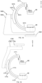
- the C-shaped arm device 1450 may include a supporting main body part 1460, a C-shaped main body part 1470 connected to the supporting main body part 1460, a detector 80 connected to a first end 1471 of the C-shaped main body part 1470, and a radiation source 90 connected to a second end 1472 of the C-shaped main body part 1470. At least one of the detector 80 or the radiation source 90 may be connected to the C-shaped main body part 1470 through the lift assembly 1200 described above.
- the lift assembly 1200 at least includes a driving assembly 1220, a first movable part, and a second movable part.
- the first movable part may be equivalent to the intermediate arm section 1231 in the foregoing embodiments
- the second movable part may be equivalent to the target arm section 1233 in the foregoing embodiments.
- a moving distance of the second movable part may be greater than a moving distance of the first movable part, e.g., the moving distance of the second movable part is twice the moving distance of the first movable part.
- the lift assembly 1200 may further include a third movable part.
- the third movable part may be driven and move in a same direction as the direction along the source image distance adjustment path to adjust the source image distance.
- the third movable part may be arranged between the first movable part and the second movable part. If the lift assembly 1200 includes the third movable part, the second movable part may be equivalent to the target arm section 1233 in the foregoing embodiments, and the third movable part may be equivalent to the third arm section in the foregoing embodiments.
- the robotic arm device 1461 may be a multi-degree-of-freedom flexible robotic arm or a rigid robotic arm.
- the flexible robotic arm may be bent by using a lightweight elastic rod as its main structure, such as an octopus arm, an elephant trunk and other biological organ bionic robotic arms.
- the rigid robotic arm may be composed of rigid links with discrete joints, such as the robotic arm of an industrial robot.
- the robotic arm device 1461 may include a data transmission system (not shown in the figure) configured to transmit image data obtained by the detector 80 to a computer system (not shown in the figure) of the X-ray device for image processing.
- the robotic arm device may be applied to medium and small size C-shaped arm X-ray machines to perform a partial angiography operation, a partial photography operation, a complex interventional operation, etc.
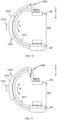
- FIG. 18 is a first schematic diagram illustrating a connection between other supporting main body parts and a C-shaped main body part according to some embodiments of the present disclosure.
- FIG. 19 is a second schematic diagram illustrating a connection between other supporting main body parts and a C-shaped main body part according to some embodiments of the present disclosure.
- a supporting main body part 1660 may further include a base 1661 and a gantry 1664.
- a supporting main body part 1760 may further include a base 1762 and a suspension device 1763. The base 1762 may be fixed on the ceiling, so that a C-shaped main body part 1770 may be suspended in the air.
- the operator may employ different types of C-shaped main body parts according to the requirements of the clinical operation.
- the C-shaped main body part 1470 may be the C-shaped arm.
- the C-shaped main body part 1670 (or 1770) may include a first arc body 1673 (or 1773) and a second arc body 1674 (or 1774).
- the first arc body 1673 (or 1773) includes a first end 1671 (or 1771) and a second end 1672 (or 1772) that are respectively connected to the detector 80 and the radiation source 90, and the second arc body 1674 (or 1774) is connected to the supporting main body part 1660 (or 1760).
- the first arc body 1673 (or 1773) and the second arc body 1674 (or 1774) may rotate relative to each other. In this way, a special placement angle between a connection line between the detector 80 and the radiation source 90 and the object observed may be present, so that the operator can observe images at some angles in a targeted manner.
- the detector 80 may be connected to the first end 1471 of the C-shaped main body part 1470 through the shell 1410 of the lift assembly 1200, and the radiation source 90 may be connected to the second end 1472 of the C-shaped main body part 1470 using a relatively fixed or rotatable connection manner.
- the detector 80 may move vertically upward or vertically downward in the first direction through the lift assembly 1200, while the radiation source 90 remains unchanged in the first direction relative to the detector 80.
- the lift assembly 1200 may be in an extended state, and the distance between the detector 80 and the radiation source 90 may be the smallest.
- the beneficial effects of the lift assembly and the C-shaped arm device for the X-ray device may include but be not limited to: (1) a lift assembly capable of adjusting the distance between the detector and the radiation source may be provided; (2) the lift assembly includes two or more arm sections, and the moving path length of the target arm section may be twice that of the previous arm section (for example, the intermediate arm section) through the linkage assembly between the two adjacent arm sections, so that the shell supporting the intermediate arm section may have a relatively small size, thereby realizing a relatively large moving path length of the target arm section; (3) the C-shaped arm device using the aforementioned lift assembly may achieve a compact structure, and may release a part of an operation space of the C-shaped arm device, so as to satisfy the needs of a large opening and a large operation space for the C-shaped arm in the clinical operation.
Landscapes
- Health & Medical Sciences (AREA)
- Life Sciences & Earth Sciences (AREA)
- Engineering & Computer Science (AREA)
- Medical Informatics (AREA)
- Heart & Thoracic Surgery (AREA)
- Animal Behavior & Ethology (AREA)
- Biophysics (AREA)
- Nuclear Medicine, Radiotherapy & Molecular Imaging (AREA)
- Optics & Photonics (AREA)
- Pathology (AREA)
- Radiology & Medical Imaging (AREA)
- Biomedical Technology (AREA)
- Physics & Mathematics (AREA)
- Molecular Biology (AREA)
- Surgery (AREA)
- High Energy & Nuclear Physics (AREA)
- General Health & Medical Sciences (AREA)
- Public Health (AREA)
- Veterinary Medicine (AREA)
- Pulmonology (AREA)
- Theoretical Computer Science (AREA)
- Automation & Control Theory (AREA)
- Robotics (AREA)
- Computer Vision & Pattern Recognition (AREA)
- Apparatus For Radiation Diagnosis (AREA)
Claims (14)
- Scaneinrichtung (110), die ein Portal (1164, 1072), eine Steuereinheit, einen C-förmigen Arm (710), eine Strahlungsquelle (112, 712, 90) und einen Detektor (113,80) beinhaltet, wobeidie Strahlungsquelle und der Detektor an beiden Enden des C-förmigen Arms angeordnet sind, das Portal eine Roboterarmanordnung (730) beinhaltet, die Roboterarmanordnung mehrere Freiheitsgrade aufweist und der C-förmige Arm drehbar an einem Ende der Roboterarmanordnung angeordnet ist,der C-förmige Arm mit dem Portal verbunden ist, unddie Steuereinheit konfiguriert ist, eine Bewegung des Portals zu steuern, um den C-förmigen Arm anzutreiben, sich zu bewegen, um ein Zielobjekt zu scannen,die Scaneinrichtung eine Kegelstrahl-Computertomographie-Scaneinrichtung ist und das Portal einen Ablenkmodus und einen Drehmodus aufweist, wobeidie Roboterarmanordnung im Ablenkmodus die Strahlungsquelle und den Detektor antreibt, um um einen Mittelpunkt des Detektors abgelenkt zu werden, wobei der Mittelpunkt des Detektors ein geometrischer Mittelpunkt des Detektors ist und während der Ablenkung unverändert bleibt,das Portal im Drehmodus die Strahlungsquelle und den Detektor antreibt, um sie um einen Mittelpunkt von Interesse eines Zielobjekts zu drehen, um das Zielobjekt zu scannen und Scandaten des Zielobjekts zu erhalten,die Strahlungsquelle und der Detektor vor der Ablenkung ein erstes Rekonstruktionssichtfeld (FOV) aufweisen, die Strahlungsquelle und der Detektor nach der Ablenkung ein zweites Rekonstruktions-FOV aufweisen und das zweite Rekonstruktions-FOV größer ist als das erste Rekonstruktions-FOV.
- Scaneinrichtung nach Anspruch 1, wobei eine Scanansicht eines einzigen Einzelbildes nach der Ablenkung der Strahlungsquelle und des Detektors mindestens die Hälfte des zweiten Rekonstruktions-FOV abdeckt.
- Scaneinrichtung nach einem der Ansprüche 1-2, wobei die Strahlungsquelle an einem Ende des C-förmigen Arms unter der Steuerung der Steuereinheit konfiguriert ist, sich in einer ersten Richtung zu bewegen, während sie eine kreisförmige Scanbewegung ausführt.
- Scaneinrichtung nach Anspruch 3, wobei die Strahlungsquelle unter der Steuerung der Steuereinheit konfiguriert ist, entlang einer spiralförmigen Bahn zu scannen.
- Scaneinrichtung nach Anspruch 3, wobei die Strahlungsquelle unter der Steuerung der Steuereinheit abwechselnd eine Kreisbewegung in einer Richtung im Uhrzeigersinn und einer Richtung gegen den Uhrzeigersinn ausführt, während sie sich in der ersten Richtung bewegt, sodass die Strahlungsquelle entlang einer hin- und hergehenden spiralförmigen Bahn scannt.
- Scaneinrichtung nach einem der Ansprüche 3-5, wobei die erste Richtung senkrecht zu einer Umfangsebene verläuft, die gebildet wird, wenn die Strahlungsquelle eine Kreisbewegung aufweist.
- Scaneinrichtung nach einem der Ansprüche 3-5, wobei die erste Richtung einen ersten beinhalteten Winkel mit einer senkrechten Linie einer Umfangsebene bildet, die gebildet wird, wenn die Strahlungsquelle eine Kreisbewegung aufweist, und der erste eingeschlossene Winkel kleiner als ein voreingestellter Schwellenwert ist.
- Scaneinrichtung nach einem der Ansprüche 3-7, wobei die erste Richtung eine Erstreckungsrichtung eines Scanbetts ist.
- Scaneinrichtung nach einem der Ansprüche 3-8, wobei die Steuereinheit konfiguriert ist, die Strahlungsquelle zu steuern, sich in der ersten Richtung zu bewegen, während die kreisförmige Scanbewegung innerhalb eines Scanbereichs ausgeführt wird, und der Scanbereich einen Zielscanbereich abdeckt.
- Scaneinrichtung nach einem der Ansprüche 1-9, wobei mindestens eines von dem Detektor oder der Strahlungsquelle über eine Hebeanordnung mit dem C-förmigen Arm verbunden ist, wobei die Hebeanordnung umfasst:ein Gehäuse (1210);eine Antriebsanordnung (1220), die in dem Gehäuse untergebracht ist; undeine Armanpassungsanordnung (1230), wobei sich die Armanpassungsanordnung unter einem Antrieb der Antriebsanordnung bewegt, wobeidie Armanpassungsanordnung einen Zwischenarmabschnitt (1231), einen Zielarmabschnitt (1233) und eine Verbindungsanordnung beinhaltet, die zwischen dem Zwischenarmabschnitt und dem Zielarmabschnitt angeordnet ist,der Zwischenarmabschnitt sich unter dem Antrieb der Antriebsanordnung in einer ersten Richtung bewegt,wenn sich der Zwischenarmabschnitt in der ersten Richtung bewegt, der Zielarmabschnitt durch die Verbindungsanordnung angetrieben wird, um sich in der ersten Richtung zu bewegen,Vorsprünge des Zwischenarmabschnitts undder Zielarmabschnitt sich jeweils in der ersten Richtung mindestens teilweise überlappen, und der Zielarmabschnitt mit dem Detektor oder der Strahlungsquelle verbunden ist.
- Scaneinrichtung nach Anspruch 10, wobei,die Verbindungsanordnung eine erste Stützkomponente (2351) und eine zweite Stützkomponente (2352), die am Zwischenarmabschnitt angeordnet sind, eine erste flexible Traktionskomponente (2354), die mit der ersten Stützkomponente verbunden ist, und eine zweite flexible Traktionskomponente, die mit der zweiten Stützkomponente verbunden ist, beinhaltet;ein Ende der ersten flexiblen Traktionskomponente mit dem Gehäuse verbunden ist, das andere Ende der ersten flexiblen Traktionskomponente mit dem Zielarmabschnitt verbunden ist; ein Ende der zweiten flexiblen Traktionskomponente mit dem Gehäuse verbunden ist, und das andere Ende der zweiten flexiblen Traktionskomponente mit dem Zielarmabschnitt verbunden ist.
- Scaneinrichtung nach Anspruch 10 oder Anspruch 11, wobei die Verbindungsanordnung weiter beinhaltet:einen ersten Gleitblock (2355) undeine erste Führungsschiene, die mit dem ersten Gleitblock zusammenpasst, wobei der erste Gleitblock an einem von dem Zwischenarmabschnitt und dem Zielarmabschnitt angeordnet ist und die erste Führungsschiene an dem anderen von dem Zwischenarmabschnitt und dem Zielarmabschnitt angeordnet ist.
- Scaneinrichtung nach einem der Ansprüche 10-12, wobei die Hebeanordnung weiter beinhaltet:
eine zwischen der Antriebsanordnung und dem Zwischenarmabschnitt angeordnete Übertragungsanordnung, die für eine Übertragung zwischen der Antriebsanordnung und dem Zwischenarmabschnitt konfiguriert ist. - Verfahren zum Erhalten eines medizinischen Bildes, wobei das Verfahren durch eine Kegelstrahl-Computertomographie-Scaneinrichtung (110) implementiert wird, die Kegelstrahl-Computertomographie-Scaneinrichtung eine Strahlungsquelle (112, 712, 90), einen Detektor (113, 80), ein Portal (1164,1072) und einen C-förmigen Arm (710) beinhaltet, die Strahlungsquelle und der Detektor an beiden Enden des C-förmigen Arms angeordnet sind, das Portal eine Roboterarmanordnung (730) beinhaltet, die Roboterarmanordnung mehrere Freiheitsgrade aufweist und der C-förmige Arm drehbar an einem Ende der Roboterarmanordnung angeordnet ist; wobei das Verfahren umfasst:Ablenken der Strahlungsquelle und des Detektors um einen Mittelpunkt des Detektors, wobei die Strahlungsquelle und der Detektor während der Ablenkung durch die Roboterarmanordnung angetrieben werden und der Mittelpunkt des Detektors zu einem geometrischen Mittelpunkt des Detektors ausgerichtet ist und unverändert bleibt; undDrehen der abgelenkten Strahlungsquelle und des abgelenkten Detektors um einen Mittelpunkt von Interesse eines Zielobjekts, um das Zielobjekt zu scannen, und Erhalten von Scandaten des Zielobjekts,wobei die Strahlungsquelle und der Detektor vor der Ablenkung ein erstes Rekonstruktions-FOV aufweisen, die Strahlungsquelle und der Detektor nach der Ablenkung ein zweites Rekonstruktions-FOV aufweisen und das zweite Rekonstruktions-FOV größer ist als das erste Rekonstruktions-FOV.
Priority Applications (1)
| Application Number | Priority Date | Filing Date | Title |
|---|---|---|---|
| EP25166622.8A EP4555938B1 (de) | 2020-05-09 | 2021-05-10 | Abtastsystem |
Applications Claiming Priority (4)
| Application Number | Priority Date | Filing Date | Title |
|---|---|---|---|
| CN202010387550.9A CN111528882A (zh) | 2020-05-09 | 2020-05-09 | 一种用于x射线设备的升降组件以及c臂装置 |
| CN202010385474.8A CN111528881B (zh) | 2020-05-09 | 2020-05-09 | 一种基于c型臂的扫描系统 |
| CN202010387567.4A CN111528890B (zh) | 2020-05-09 | 2020-05-09 | 一种医学图像获取方法和系统 |
| PCT/CN2021/092898 WO2021228056A1 (zh) | 2020-05-09 | 2021-05-10 | 一种扫描装置、方法及系统 |
Related Child Applications (1)
| Application Number | Title | Priority Date | Filing Date |
|---|---|---|---|
| EP25166622.8A Division EP4555938B1 (de) | 2020-05-09 | 2021-05-10 | Abtastsystem |
Publications (3)
| Publication Number | Publication Date |
|---|---|
| EP4134007A1 EP4134007A1 (de) | 2023-02-15 |
| EP4134007A4 EP4134007A4 (de) | 2023-11-22 |
| EP4134007B1 true EP4134007B1 (de) | 2025-04-16 |
Family
ID=78525276
Family Applications (2)
| Application Number | Title | Priority Date | Filing Date |
|---|---|---|---|
| EP21802999.9A Active EP4134007B1 (de) | 2020-05-09 | 2021-05-10 | Abtastvorrichtung sowie verfahren |
| EP25166622.8A Active EP4555938B1 (de) | 2020-05-09 | 2021-05-10 | Abtastsystem |
Family Applications After (1)
| Application Number | Title | Priority Date | Filing Date |
|---|---|---|---|
| EP25166622.8A Active EP4555938B1 (de) | 2020-05-09 | 2021-05-10 | Abtastsystem |
Country Status (3)
| Country | Link |
|---|---|
| US (1) | US12263027B2 (de) |
| EP (2) | EP4134007B1 (de) |
| WO (1) | WO2021228056A1 (de) |
Families Citing this family (13)
| Publication number | Priority date | Publication date | Assignee | Title |
|---|---|---|---|---|
| JP1701895S (de) * | 2021-04-15 | 2021-12-13 | ||
| JP1701891S (de) * | 2021-04-15 | 2021-12-13 | ||
| JP1701894S (de) * | 2021-04-15 | 2021-12-13 | ||
| JP1701893S (de) * | 2021-04-15 | 2021-12-13 | ||
| JP1701892S (de) * | 2021-04-15 | 2021-12-13 | ||
| CN114224371B (zh) * | 2021-12-31 | 2025-04-08 | 深圳市深图医学影像设备有限公司 | 变sid可移动式cbct |
| CN114609161B (zh) * | 2022-03-07 | 2024-10-11 | 艾偲睿科技(厦门)有限责任公司 | 一种基于智能交互平台的x射线自动检测系统及方法 |
| US20240070937A1 (en) * | 2022-08-31 | 2024-02-29 | Canon Medical Systems Corporation | Medical image processing apparatus, medical image processing method, and x-ray diagnostic apparatus |
| USD1118932S1 (en) * | 2024-02-28 | 2026-03-17 | Metaltronica S.P.A. | Irradiation apparatus |
| JP1803712S (ja) * | 2024-03-13 | 2025-07-15 | 血管造影エックス線機器 | |
| US20250318793A1 (en) * | 2024-04-12 | 2025-10-16 | Turner Imaging Systems, Inc. | C-arm x-ray imaging devices with repositionable x-ray source or detector |
| USD1121819S1 (en) * | 2024-09-26 | 2026-04-07 | GE Precision Healthcare LLC | Imaging apparatus |
| USD1101152S1 (en) * | 2024-09-26 | 2025-11-04 | GE Precision Healthcare LLC | Imaging apparatus |
Family Cites Families (35)
| Publication number | Priority date | Publication date | Assignee | Title |
|---|---|---|---|---|
| US5430783A (en) | 1992-08-07 | 1995-07-04 | General Electric Company | Reconstruction method for helical scanning computed tomography apparatus with multi-row detector array employing overlapping beams |
| DE19947809A1 (de) * | 1999-10-05 | 2001-04-12 | Philips Corp Intellectual Pty | C-Bogen-Röntgeneinrichtung |
| JP3490699B2 (ja) | 2001-06-18 | 2004-01-26 | 株式会社東芝 | X線コンピュータ断層撮影装置 |
| JP4030827B2 (ja) | 2002-08-13 | 2008-01-09 | ジーイー・メディカル・システムズ・グローバル・テクノロジー・カンパニー・エルエルシー | 投影データ作成方法、画素データ作成方法およびマルチ検出器x線ct装置 |
| JP4056922B2 (ja) | 2003-04-21 | 2008-03-05 | ジーイー・メディカル・システムズ・グローバル・テクノロジー・カンパニー・エルエルシー | 放射線計算断層画像装置 |
| CN101505658B (zh) | 2006-08-17 | 2015-08-19 | 皇家飞利浦电子股份有限公司 | 计算机断层摄影图像获取 |
| DE102006041033B4 (de) | 2006-09-01 | 2017-01-19 | Siemens Healthcare Gmbh | Verfahren zur Rekonstruktion eines dreidimensionalen Bildvolumens |
| JP2008125909A (ja) | 2006-11-22 | 2008-06-05 | Ge Medical Systems Global Technology Co Llc | X線ct装置 |
| DE102008003815B4 (de) | 2008-01-10 | 2014-07-31 | Siemens Aktiengesellschaft | Röntgeneinrichtung umfassend einen vorzugsweise an einem Roboterarm um eine Drehachse drehbar gelagerten C-Bogen |
| WO2009101543A1 (en) | 2008-02-14 | 2009-08-20 | Koninklijke Philips Electronics N.V. | Multiple-source imaging system with flat-panel detector |
| US8379791B2 (en) | 2008-10-10 | 2013-02-19 | Koninklijke Philips Electronics N.V. | Method and apparatus to improve CT image acquisition using a displaced geometry |
| CN103349556B (zh) | 2009-01-21 | 2015-09-23 | 皇家飞利浦电子股份有限公司 | 用于大视场成像及运动伪影的探测和补偿的方法和装置 |
| WO2011015957A1 (en) * | 2009-08-06 | 2011-02-10 | Koninklijke Philips Electronics N.V. | Method and apparatus for generating computed tomography images with offset detector geometries |
| RU2561512C2 (ru) * | 2009-10-06 | 2015-08-27 | Конинклейке Филипс Электроникс Н.В. | Стол для пациента, содержащий систему позиционирования, а также способ использования такого стола для пациента |
| CN202288320U (zh) | 2011-10-31 | 2012-07-04 | 上海西门子医疗器械有限公司 | C臂组件、及x射线设备 |
| DE102011086754B4 (de) | 2011-11-21 | 2021-05-20 | Siemens Healthcare Gmbh | C-Bogensystem zur rotatorischen Abtastung eines Objektes |
| DE102012211998B4 (de) * | 2012-07-10 | 2024-08-08 | Siemens Healthineers Ag | Computertomograph und Verfahren zum Gewinnen eines Volumenmodells von einem Körper mittels des Computertomographen |
| US9468409B2 (en) * | 2012-11-30 | 2016-10-18 | General Electric Company | Systems and methods for imaging dynamic processes |
| EP3175791B1 (de) * | 2013-11-04 | 2021-09-08 | Ecential Robotics | Verfahren zur rekonstruktion eines 3d-bildes aus 2d-röntgenbildern |
| DE102013223786B3 (de) | 2013-11-21 | 2014-12-24 | Siemens Aktiengesellschaft | Angiographisches Untersuchungsverfahren eines Untersuchungsobjekts zur Durchführung von Rotationsangiographien |
| DE102013226289A1 (de) * | 2013-12-17 | 2015-06-18 | Kuka Laboratories Gmbh | Röntgenvorrichtung mit einer Verstelleinrichtung |
| DE102015215938A1 (de) * | 2015-08-20 | 2017-02-23 | Siemens Healthcare Gmbh | Verfahren zur lokalen Verbesserung der Bildqualität |
| US10117632B2 (en) * | 2016-02-03 | 2018-11-06 | Globus Medical, Inc. | Portable medical imaging system with beam scanning collimator |
| CN106430000B (zh) | 2016-10-13 | 2018-07-03 | 国网山东省电力公司商河县供电公司 | 一种三级联动式电力辅助伸缩平台 |
| CN107714062A (zh) | 2017-09-18 | 2018-02-23 | 北京中拓奕腾科技有限公司 | 集成医用数字化x射线摄影系统的多功能检查设备 |
| US11311257B2 (en) * | 2018-08-14 | 2022-04-26 | General Electric Company | Systems and methods for a mobile x-ray imaging system |
| DE102018217046A1 (de) * | 2018-10-05 | 2020-04-09 | Dornier Medtech Systems Gmbh | Lithotripsievorrichtung und -verfahren |
| CN109626260B (zh) | 2018-12-18 | 2021-08-03 | 上海联影医疗科技股份有限公司 | 一种横臂升降组件及移动式放射线装置 |
| CN209652877U (zh) | 2019-01-16 | 2019-11-19 | 山东华水水利机械科技有限公司 | 一种防渗渠成型装置及现浇成型机 |
| CN110811655B (zh) | 2019-11-21 | 2021-08-10 | 上海联影医疗科技股份有限公司 | 一种c型臂及x射线机 |
| CN114209346A (zh) * | 2019-11-21 | 2022-03-22 | 上海联影医疗科技股份有限公司 | 一种c型臂及数字减影血管造影设备 |
| CN111096760A (zh) * | 2019-12-30 | 2020-05-05 | 上海联影医疗科技有限公司 | 放射成像设备及其运动控制方法、系统、介质及存储介质 |
| CN111528882A (zh) * | 2020-05-09 | 2020-08-14 | 上海联影医疗科技有限公司 | 一种用于x射线设备的升降组件以及c臂装置 |
| CN111528881B (zh) * | 2020-05-09 | 2023-08-18 | 上海联影医疗科技股份有限公司 | 一种基于c型臂的扫描系统 |
| CN118340535A (zh) * | 2020-05-09 | 2024-07-16 | 上海联影医疗科技股份有限公司 | 一种医学扫描成像设备以及医学图像获取方法 |
-
2021
- 2021-05-10 WO PCT/CN2021/092898 patent/WO2021228056A1/zh not_active Ceased
- 2021-05-10 EP EP21802999.9A patent/EP4134007B1/de active Active
- 2021-05-10 EP EP25166622.8A patent/EP4555938B1/de active Active
-
2022
- 2022-11-09 US US18/054,123 patent/US12263027B2/en active Active
Also Published As
| Publication number | Publication date |
|---|---|
| EP4555938A3 (de) | 2025-08-13 |
| EP4555938B1 (de) | 2026-05-20 |
| US20230092496A1 (en) | 2023-03-23 |
| EP4134007A4 (de) | 2023-11-22 |
| WO2021228056A1 (zh) | 2021-11-18 |
| US12263027B2 (en) | 2025-04-01 |
| EP4134007A1 (de) | 2023-02-15 |
| EP4555938A2 (de) | 2025-05-21 |
Similar Documents
| Publication | Publication Date | Title |
|---|---|---|
| US12263027B2 (en) | Scanning apparatus, method, and system | |
| US11737714B2 (en) | Cone-beam computed tomography imaging devices, systems, and methods | |
| CN111528890B (zh) | 一种医学图像获取方法和系统 | |
| EP2903521B1 (de) | Extremitätenbildgebungsvorrichtung für digitale volumentomografie durch ein kegelförmiges strahlenbündel | |
| US10548540B2 (en) | Extremity imaging apparatus for cone beam computed tomography | |
| KR101103133B1 (ko) | 방사선 촬영 장치 | |
| JP7436443B2 (ja) | X線診断装置 | |
| US20250228510A1 (en) | Scanning apparatus, method, and system | |
| JP2020518403A (ja) | 3次元x線イメージングシステム | |
| JP7657854B2 (ja) | 2つのキャリッジを有する統合フィルタアセンブリ用のシステム及び方法 | |
| US12059282B2 (en) | Medical imaging system with contoured detector | |
| US20160364525A1 (en) | Medical image processing apparatus and medical image transfer system | |
| WO2022068941A1 (en) | Systems and methods for digital radiography | |
| JP2019030410A (ja) | X線ct装置及びx線ctシステム | |
| JP2019180834A (ja) | X線ct装置 | |
| CN111528881B (zh) | 一种基于c型臂的扫描系统 | |
| JP7599851B2 (ja) | 医用情報処理装置、医用情報処理方法、プログラムおよびct搭載車 | |
| JP7485539B2 (ja) | X線診断装置及び検出器収容装置 | |
| JP7395385B2 (ja) | アンギオct装置 | |
| JP2024081035A (ja) | 医用画像診断装置、医用画像診断方法及び医用画像診断プログラム | |
| JP2022172743A (ja) | 医用画像処理装置、医用画像処理方法及びプログラム | |
| JP2023071179A (ja) | 医用画像処理装置、x線ct装置、医用画像処理方法及びプログラム | |
| JP2023025939A (ja) | X線の線質調整装置およびx線コンピュータ断層撮影装置 |
Legal Events
| Date | Code | Title | Description |
|---|---|---|---|
| STAA | Information on the status of an ep patent application or granted ep patent |
Free format text: STATUS: THE INTERNATIONAL PUBLICATION HAS BEEN MADE |
|
| PUAI | Public reference made under article 153(3) epc to a published international application that has entered the european phase |
Free format text: ORIGINAL CODE: 0009012 |
|
| STAA | Information on the status of an ep patent application or granted ep patent |
Free format text: STATUS: REQUEST FOR EXAMINATION WAS MADE |
|
| 17P | Request for examination filed |
Effective date: 20221109 |
|
| AK | Designated contracting states |
Kind code of ref document: A1 Designated state(s): AL AT BE BG CH CY CZ DE DK EE ES FI FR GB GR HR HU IE IS IT LI LT LU LV MC MK MT NL NO PL PT RO RS SE SI SK SM TR |
|
| DAV | Request for validation of the european patent (deleted) | ||
| DAX | Request for extension of the european patent (deleted) | ||
| A4 | Supplementary search report drawn up and despatched |
Effective date: 20231024 |
|
| RIC1 | Information provided on ipc code assigned before grant |
Ipc: A61B 6/00 20060101AFI20231018BHEP |
|
| GRAP | Despatch of communication of intention to grant a patent |
Free format text: ORIGINAL CODE: EPIDOSNIGR1 |
|
| STAA | Information on the status of an ep patent application or granted ep patent |
Free format text: STATUS: GRANT OF PATENT IS INTENDED |
|
| RIC1 | Information provided on ipc code assigned before grant |
Ipc: A61B 6/40 20240101ALI20241121BHEP Ipc: A61B 6/03 20060101ALI20241121BHEP Ipc: A61B 6/00 20060101AFI20241121BHEP |
|
| INTG | Intention to grant announced |
Effective date: 20241209 |
|
| GRAS | Grant fee paid |
Free format text: ORIGINAL CODE: EPIDOSNIGR3 |
|
| GRAA | (expected) grant |
Free format text: ORIGINAL CODE: 0009210 |
|
| STAA | Information on the status of an ep patent application or granted ep patent |
Free format text: STATUS: THE PATENT HAS BEEN GRANTED |
|
| AK | Designated contracting states |
Kind code of ref document: B1 Designated state(s): AL AT BE BG CH CY CZ DE DK EE ES FI FR GB GR HR HU IE IS IT LI LT LU LV MC MK MT NL NO PL PT RO RS SE SI SK SM TR |
|
| REG | Reference to a national code |
Ref country code: GB Ref legal event code: FG4D |
|
| REG | Reference to a national code |
Ref country code: CH Ref legal event code: EP |
|
| REG | Reference to a national code |
Ref country code: IE Ref legal event code: FG4D |
|
| REG | Reference to a national code |
Ref country code: DE Ref legal event code: R096 Ref document number: 602021029315 Country of ref document: DE |
|
| PGFP | Annual fee paid to national office [announced via postgrant information from national office to epo] |
Ref country code: AT Payment date: 20250721 Year of fee payment: 5 |
|
| REG | Reference to a national code |
Ref country code: NL Ref legal event code: MP Effective date: 20250416 |
|
| PG25 | Lapsed in a contracting state [announced via postgrant information from national office to epo] |
Ref country code: NL Free format text: LAPSE BECAUSE OF FAILURE TO SUBMIT A TRANSLATION OF THE DESCRIPTION OR TO PAY THE FEE WITHIN THE PRESCRIBED TIME-LIMIT Effective date: 20250416 |
|
| REG | Reference to a national code |
Ref country code: AT Ref legal event code: MK05 Ref document number: 1784969 Country of ref document: AT Kind code of ref document: T Effective date: 20250416 |
|
| PG25 | Lapsed in a contracting state [announced via postgrant information from national office to epo] |
Ref country code: FI Free format text: LAPSE BECAUSE OF FAILURE TO SUBMIT A TRANSLATION OF THE DESCRIPTION OR TO PAY THE FEE WITHIN THE PRESCRIBED TIME-LIMIT Effective date: 20250416 Ref country code: ES Free format text: LAPSE BECAUSE OF FAILURE TO SUBMIT A TRANSLATION OF THE DESCRIPTION OR TO PAY THE FEE WITHIN THE PRESCRIBED TIME-LIMIT Effective date: 20250416 Ref country code: PT Free format text: LAPSE BECAUSE OF FAILURE TO SUBMIT A TRANSLATION OF THE DESCRIPTION OR TO PAY THE FEE WITHIN THE PRESCRIBED TIME-LIMIT Effective date: 20250818 |
|
| REG | Reference to a national code |
Ref country code: LT Ref legal event code: MG9D |
|
| PG25 | Lapsed in a contracting state [announced via postgrant information from national office to epo] |
Ref country code: NO Free format text: LAPSE BECAUSE OF FAILURE TO SUBMIT A TRANSLATION OF THE DESCRIPTION OR TO PAY THE FEE WITHIN THE PRESCRIBED TIME-LIMIT Effective date: 20250716 Ref country code: GR Free format text: LAPSE BECAUSE OF FAILURE TO SUBMIT A TRANSLATION OF THE DESCRIPTION OR TO PAY THE FEE WITHIN THE PRESCRIBED TIME-LIMIT Effective date: 20250717 |
|
| PG25 | Lapsed in a contracting state [announced via postgrant information from national office to epo] |
Ref country code: PL Free format text: LAPSE BECAUSE OF FAILURE TO SUBMIT A TRANSLATION OF THE DESCRIPTION OR TO PAY THE FEE WITHIN THE PRESCRIBED TIME-LIMIT Effective date: 20250416 |
|
| PG25 | Lapsed in a contracting state [announced via postgrant information from national office to epo] |
Ref country code: BG Free format text: LAPSE BECAUSE OF FAILURE TO SUBMIT A TRANSLATION OF THE DESCRIPTION OR TO PAY THE FEE WITHIN THE PRESCRIBED TIME-LIMIT Effective date: 20250416 |
|
| PG25 | Lapsed in a contracting state [announced via postgrant information from national office to epo] |
Ref country code: HR Free format text: LAPSE BECAUSE OF FAILURE TO SUBMIT A TRANSLATION OF THE DESCRIPTION OR TO PAY THE FEE WITHIN THE PRESCRIBED TIME-LIMIT Effective date: 20250416 |
|
| PG25 | Lapsed in a contracting state [announced via postgrant information from national office to epo] |
Ref country code: AT Free format text: LAPSE BECAUSE OF FAILURE TO SUBMIT A TRANSLATION OF THE DESCRIPTION OR TO PAY THE FEE WITHIN THE PRESCRIBED TIME-LIMIT Effective date: 20250416 |
|
| PG25 | Lapsed in a contracting state [announced via postgrant information from national office to epo] |
Ref country code: RS Free format text: LAPSE BECAUSE OF FAILURE TO SUBMIT A TRANSLATION OF THE DESCRIPTION OR TO PAY THE FEE WITHIN THE PRESCRIBED TIME-LIMIT Effective date: 20250716 |
|
| PG25 | Lapsed in a contracting state [announced via postgrant information from national office to epo] |
Ref country code: IS Free format text: LAPSE BECAUSE OF FAILURE TO SUBMIT A TRANSLATION OF THE DESCRIPTION OR TO PAY THE FEE WITHIN THE PRESCRIBED TIME-LIMIT Effective date: 20250816 |
|
| PG25 | Lapsed in a contracting state [announced via postgrant information from national office to epo] |
Ref country code: LV Free format text: LAPSE BECAUSE OF FAILURE TO SUBMIT A TRANSLATION OF THE DESCRIPTION OR TO PAY THE FEE WITHIN THE PRESCRIBED TIME-LIMIT Effective date: 20250416 |
|
| REG | Reference to a national code |
Ref country code: CH Ref legal event code: H13 Free format text: ST27 STATUS EVENT CODE: U-0-0-H10-H13 (AS PROVIDED BY THE NATIONAL OFFICE) Effective date: 20251223 |
|
| PG25 | Lapsed in a contracting state [announced via postgrant information from national office to epo] |
Ref country code: SM Free format text: LAPSE BECAUSE OF FAILURE TO SUBMIT A TRANSLATION OF THE DESCRIPTION OR TO PAY THE FEE WITHIN THE PRESCRIBED TIME-LIMIT Effective date: 20250416 Ref country code: DK Free format text: LAPSE BECAUSE OF FAILURE TO SUBMIT A TRANSLATION OF THE DESCRIPTION OR TO PAY THE FEE WITHIN THE PRESCRIBED TIME-LIMIT Effective date: 20250416 |
|
| PG25 | Lapsed in a contracting state [announced via postgrant information from national office to epo] |
Ref country code: LU Free format text: LAPSE BECAUSE OF NON-PAYMENT OF DUE FEES Effective date: 20250510 |
|
| PG25 | Lapsed in a contracting state [announced via postgrant information from national office to epo] |
Ref country code: CH Free format text: LAPSE BECAUSE OF NON-PAYMENT OF DUE FEES Effective date: 20250531 |
|
| REG | Reference to a national code |
Ref country code: DE Ref legal event code: R097 Ref document number: 602021029315 Country of ref document: DE |
|
| PG25 | Lapsed in a contracting state [announced via postgrant information from national office to epo] |
Ref country code: CZ Free format text: LAPSE BECAUSE OF FAILURE TO SUBMIT A TRANSLATION OF THE DESCRIPTION OR TO PAY THE FEE WITHIN THE PRESCRIBED TIME-LIMIT Effective date: 20250416 |
|
| PG25 | Lapsed in a contracting state [announced via postgrant information from national office to epo] |
Ref country code: EE Free format text: LAPSE BECAUSE OF FAILURE TO SUBMIT A TRANSLATION OF THE DESCRIPTION OR TO PAY THE FEE WITHIN THE PRESCRIBED TIME-LIMIT Effective date: 20250416 |
|
| PG25 | Lapsed in a contracting state [announced via postgrant information from national office to epo] |
Ref country code: SK Free format text: LAPSE BECAUSE OF FAILURE TO SUBMIT A TRANSLATION OF THE DESCRIPTION OR TO PAY THE FEE WITHIN THE PRESCRIBED TIME-LIMIT Effective date: 20250416 |
|
| PG25 | Lapsed in a contracting state [announced via postgrant information from national office to epo] |
Ref country code: IT Free format text: LAPSE BECAUSE OF FAILURE TO SUBMIT A TRANSLATION OF THE DESCRIPTION OR TO PAY THE FEE WITHIN THE PRESCRIBED TIME-LIMIT Effective date: 20250416 |
|
| REG | Reference to a national code |
Ref country code: BE Ref legal event code: MM Effective date: 20250531 |
|
| PG25 | Lapsed in a contracting state [announced via postgrant information from national office to epo] |
Ref country code: MC Free format text: LAPSE BECAUSE OF FAILURE TO SUBMIT A TRANSLATION OF THE DESCRIPTION OR TO PAY THE FEE WITHIN THE PRESCRIBED TIME-LIMIT Effective date: 20250416 |
|
| PG25 | Lapsed in a contracting state [announced via postgrant information from national office to epo] |
Ref country code: RO Free format text: LAPSE BECAUSE OF FAILURE TO SUBMIT A TRANSLATION OF THE DESCRIPTION OR TO PAY THE FEE WITHIN THE PRESCRIBED TIME-LIMIT Effective date: 20250416 |
|
| PLBE | No opposition filed within time limit |
Free format text: ORIGINAL CODE: 0009261 |
|
| STAA | Information on the status of an ep patent application or granted ep patent |
Free format text: STATUS: NO OPPOSITION FILED WITHIN TIME LIMIT |
|
| REG | Reference to a national code |
Ref country code: CH Ref legal event code: L10 Free format text: ST27 STATUS EVENT CODE: U-0-0-L10-L00 (AS PROVIDED BY THE NATIONAL OFFICE) Effective date: 20260225 |
|
| 26N | No opposition filed |
Effective date: 20260119 |
|
| PGFP | Annual fee paid to national office [announced via postgrant information from national office to epo] |
Ref country code: GB Payment date: 20260331 Year of fee payment: 6 |
|
| PG25 | Lapsed in a contracting state [announced via postgrant information from national office to epo] |
Ref country code: IE Free format text: LAPSE BECAUSE OF NON-PAYMENT OF DUE FEES Effective date: 20250510 |
|
| PG25 | Lapsed in a contracting state [announced via postgrant information from national office to epo] |
Ref country code: BE Free format text: LAPSE BECAUSE OF NON-PAYMENT OF DUE FEES Effective date: 20250531 |
|
| PG25 | Lapsed in a contracting state [announced via postgrant information from national office to epo] |
Ref country code: LT Free format text: LAPSE BECAUSE OF FAILURE TO SUBMIT A TRANSLATION OF THE DESCRIPTION OR TO PAY THE FEE WITHIN THE PRESCRIBED TIME-LIMIT Effective date: 20250416 |
|
| PGFP | Annual fee paid to national office [announced via postgrant information from national office to epo] |
Ref country code: DE Payment date: 20260522 Year of fee payment: 6 |
|
| PGFP | Annual fee paid to national office [announced via postgrant information from national office to epo] |
Ref country code: FR Payment date: 20260525 Year of fee payment: 6 |
|
| PG25 | Lapsed in a contracting state [announced via postgrant information from national office to epo] |
Ref country code: SE Free format text: LAPSE BECAUSE OF FAILURE TO SUBMIT A TRANSLATION OF THE DESCRIPTION OR TO PAY THE FEE WITHIN THE PRESCRIBED TIME-LIMIT Effective date: 20250416 Ref country code: CY Free format text: LAPSE BECAUSE OF FAILURE TO SUBMIT A TRANSLATION OF THE DESCRIPTION OR TO PAY THE FEE WITHIN THE PRESCRIBED TIME-LIMIT Effective date: 20250416 |