EP4134014A1 - Befestigungsnagel, befestigungsnagel-implantationsvorrichtung und medizinisches instrument - Google Patents
Befestigungsnagel, befestigungsnagel-implantationsvorrichtung und medizinisches instrument Download PDFInfo
- Publication number
- EP4134014A1 EP4134014A1 EP20938315.7A EP20938315A EP4134014A1 EP 4134014 A1 EP4134014 A1 EP 4134014A1 EP 20938315 A EP20938315 A EP 20938315A EP 4134014 A1 EP4134014 A1 EP 4134014A1
- Authority
- EP
- European Patent Office
- Prior art keywords
- bending
- adjustable
- fastening nail
- rotating
- handle
- Prior art date
- Legal status (The legal status is an assumption and is not a legal conclusion. Google has not performed a legal analysis and makes no representation as to the accuracy of the status listed.)
- Granted
Links
Images


Classifications
-
- A—HUMAN NECESSITIES
- A61—MEDICAL OR VETERINARY SCIENCE; HYGIENE
- A61B—DIAGNOSIS; SURGERY; IDENTIFICATION
- A61B17/00—Surgical instruments, devices or methods
- A61B17/068—Surgical staplers, e.g. containing multiple staples or clamps
-
- A—HUMAN NECESSITIES
- A61—MEDICAL OR VETERINARY SCIENCE; HYGIENE
- A61B—DIAGNOSIS; SURGERY; IDENTIFICATION
- A61B17/00—Surgical instruments, devices or methods
- A61B17/064—Surgical staples, i.e. penetrating the tissue
-
- A—HUMAN NECESSITIES
- A61—MEDICAL OR VETERINARY SCIENCE; HYGIENE
- A61B—DIAGNOSIS; SURGERY; IDENTIFICATION
- A61B17/00—Surgical instruments, devices or methods
- A61B17/04—Surgical instruments, devices or methods for suturing wounds; Holders or packages for needles or suture materials
- A61B17/0401—Suture anchors, buttons or pledgets, i.e. means for attaching sutures to bone, cartilage or soft tissue; Instruments for applying or removing suture anchors
-
- A—HUMAN NECESSITIES
- A61—MEDICAL OR VETERINARY SCIENCE; HYGIENE
- A61B—DIAGNOSIS; SURGERY; IDENTIFICATION
- A61B17/00—Surgical instruments, devices or methods
- A61B17/04—Surgical instruments, devices or methods for suturing wounds; Holders or packages for needles or suture materials
- A61B17/0401—Suture anchors, buttons or pledgets, i.e. means for attaching sutures to bone, cartilage or soft tissue; Instruments for applying or removing suture anchors
- A61B2017/0409—Instruments for applying suture anchors
-
- A—HUMAN NECESSITIES
- A61—MEDICAL OR VETERINARY SCIENCE; HYGIENE
- A61B—DIAGNOSIS; SURGERY; IDENTIFICATION
- A61B17/00—Surgical instruments, devices or methods
- A61B17/04—Surgical instruments, devices or methods for suturing wounds; Holders or packages for needles or suture materials
- A61B17/0401—Suture anchors, buttons or pledgets, i.e. means for attaching sutures to bone, cartilage or soft tissue; Instruments for applying or removing suture anchors
- A61B2017/044—Suture anchors, buttons or pledgets, i.e. means for attaching sutures to bone, cartilage or soft tissue; Instruments for applying or removing suture anchors with a threaded shaft, e.g. screws
- A61B2017/0441—Suture anchors, buttons or pledgets, i.e. means for attaching sutures to bone, cartilage or soft tissue; Instruments for applying or removing suture anchors with a threaded shaft, e.g. screws the shaft being a rigid coil or spiral
-
- A—HUMAN NECESSITIES
- A61—MEDICAL OR VETERINARY SCIENCE; HYGIENE
- A61B—DIAGNOSIS; SURGERY; IDENTIFICATION
- A61B17/00—Surgical instruments, devices or methods
- A61B17/064—Surgical staples, i.e. penetrating the tissue
- A61B2017/0649—Coils or spirals
Definitions
- the present disclosure relates to the technical field of medical instrument, and in particular, to a fastening nail, a fastening nail implanting apparatus and a medical instrument.
- the fastening nail used in the prior art is usually in simple spiral structure, and the shifting fork is enabled to be inserted into a loop at one end of the fastening nail, then the shifting fork is rotated, thereby screwing the fastening nail into the human organ or skin tissue.
- the end ring at the rear end of the fastening nail that is, the distal end often called during surgical treatment
- the shifting fork is usually in a square structure
- One of the objectives of the present disclosure includes providing a fastening nail, which can solve the technical problem that the fastening nail is easy to be loosened from the shifting fork when the fastening nail is screwed into the human tissue by using the shifting fork in the prior art, thereby delaying the completion time of the operation, increasing the risk of the patient during the operation, and being unfavorable for postoperative wound healing of the patient.
- Another object of the present disclosure includes providing a fastening nail implanting apparatus to solve the technical problem that the fastening nail is easy to be loosened from the shifting fork when the fastening nail is screwed into the human tissue by using the shifting fork in the prior art, thereby delaying the completion time of the operation, increasing the risk of the patient during the operation, and being unfavorable for postoperative wound healing of the patient.
- Another object of the present disclosure includes providing a medical instrument, which can improve the tightness of the combination between the fastening nail and the fastening nail implanting apparatus, thereby avoiding the loosening of the fastening nail from the fastening nail implanting apparatus, and facilitating quickly implanting the fastening nail into the human body.
- a fastening nail which comprises a nail seat and a spiral part, wherein a front end of the spiral part is formed as a tip, a rear end of the spiral part is fixedly connected to a front end of the nail seat, and a first positioning part is provided on an end surface of a rear end of the nail seat.
- the first positioning part comprises a positioning hole or a positioning protrusion provided on the end surface of the rear end of the nail seat.
- the positioning hole is oval, triangular, rectangular, hexagonal or waist-shaped; or, a section of the positioning protrusion is oval, triangular, rectangular, hexagonal or waist-shaped.
- a threaded hole is provided on a bottom wall of the positioning hole, the threaded hole is configured to be matched with a conveying apparatus in a manner of screw thread, and the threaded hole extends in a direction of a rotation axial line for rotation of the fastening nail.
- a center of the first positioning part is located on the rotation axial line for rotation of the fastening nail; or a plurality of first positioning parts are provided, and the plurality of first positioning parts are distributed in an array manner on the end surface of the rear end of the nail seat around the rotation axial line for rotation of the fastening nail.
- annular groove is provided on an outer peripheral surface of the nail seat, and is configured to be tied with a polymer suture for surgery.
- embodiments of the present disclosure provide a fastening nail implanting apparatus, which is configured to implant the fastening nail into a human body;
- the fastening nail comprises a nail seat and a spiral part, wherein a front end of the spiral part is formed as a tip, a rear end of the spiral part is fixedly connected to a front end of the nail seat, and a first positioning part is provided on an end surface of a rear end of the nail seat;
- the conveying cable comprises a casing pipe, a rotating cable and a spring member, and the rotating cable passes through the casing pipe;
- a rear end of the dowel pin is connected to the front end of the rotating cable by a conical surface whose diameter gradually increases in a direction from the dowel pin to the rotating cable, and a conical abutting surface matched with the conical surface is provided on an inner wall surface of the front end of the casing pipe, the rotating cable is configured to drive the dowel pin to slide back and forth inside the casing pipe, and when the conical surface abuts against the conical abutting surface provided on the inner wall surface of the front end of the casing pipe, a front end of the dowel pin protrudes from the front end of the casing pipe and is matched with the threaded hole.
- an anti-reversion part is provided between the front end of the first rotating knob and the housing, and the anti-reversion part is configured to prevent the casing pipe from rotating in an opposite direction following a second rotating shell during the process that the dowel pin rotates in the opposite direction relative to the fastening nail and thus is disengaged from the fastening nail.
- the first rotating knob comprises an end connecting rod, a first shaft rod and a first rotating shell connected from front to back in sequence, and the end connecting rod and the first shaft rod are installed inside the housing; and the anti-reversion part comprises a pawl part and a ratchet structure provided on an outer peripheral surface of the first shaft rod, and a pawl of the pawl part and the ratchet structure are engaged with each other.
- the second rotating knob comprises a second shaft rod and a second rotating shell connected to a rear end of the second shaft rod, the second shaft rod is arranged inside the first rotating shell, and a rear end of the spring member is connected to a front end of the second shaft rod.
- an anti-rotation part is detachably connected between the first rotating knob and the second rotating knob, and the anti-rotation part is configured to make the first rotating knob and the second rotating knob rotate synchronously; and a first positioning hole is provided on the end surface of the rear end of the first rotating knob, a second positioning hole penetrating through the second rotating knob in the front-rear direction is provided on the second rotating knob, and one end of the anti-rotation part extends into the first positioning hole after passing through the second positioning hole.
- the fastening nail implanting apparatus further comprises an advancing mechanism and a casing support, the advancing mechanism comprises an advancing handle, a first gear and a second gear;
- the fastening nail implanting apparatus further comprises a first bending-adjustable sheathing canal mechanism
- the first bending-adjustable sheathing canal mechanism comprises a first bending-adjustable handle and a first bending-adjustable sheathing canal
- the first bending-adjustable handle is installed on the base and located at front of the anchoring handle
- the first bending-adjustable sheathing canal is installed on the first bending-adjustable handle
- the conveying cable passes through the first bending-adjustable sheathing canal and the first bending-adjustable handle.
- the first bending-adjustable handle comprises a bending-adjustable knob, a bending-adjustable screw and a bending-adjustable sliding block, wherein the bending-adjustable sliding block is sleeved on the bending-adjustable screw in a manner of screw thread, a bending-adjustable wire is connected between a front end of the first bending-adjustable sheathing canal and the bending-adjustable sliding block, and a rear end of the bending-adjustable screw is connected with the bending-adjustable knob, and the bending-adjustable knob is configured to drive the bending-adjustable screw to rotate, so that the bending-adjustable sliding block slides in a length direction of the bending-adjustable screw, thereby tightening or releasing the bending-adjustable wire, so as to adjust a degree of curvature of the first bending-adjustable sheathing
- the fastening nail implanting apparatus further comprises a second bending-adjustable sheathing canal mechanism
- the second bending-adjustable sheathing canal mechanism comprises a second bending-adjustable handle and a second bending-adjustable sheathing canal
- the second bending-adjustable handle is installed on the base and located between the first bending-adjustable handle and the anchoring handle, and the second bending-adjustable handle may slide back and forth relative to the base
- the second bending-adjustable sheathing canal is installed on the second bending-adjustable handle, and the second bending-adjustable sheathing canal passes through the first bending-adjustable handle and the first bending-adjustable sheathing canal, and the conveying cable passes through the second bending-adjustable sheathing canal and the second bending-adjustable handle.
- the first bending-adjustable sheathing canal mechanism further comprises a first support pipe fitting; and a first sealing gasket is provided inside the first bending-adjustable handle, and a via hole with an axial line extending in a front-rear direction is provided on the first sealing gasket; a front end of the first support pipe fitting is installed on a rear end of the first bending-adjustable handle, and the front end of the first support pipe fitting is inserted into the inside of the via hole, a lumen of the first support pipe fitting communicates with the first bending-adjustable sheathing canal, and the conveying cable passes through the first bending-adjustable sheathing canal and the lumen of the first support pipe fitting.
- the first bending-adjustable handle is rotatably installed on the base through a rotating structure; and/or the second bending-adjustable handle is rotatably installed on the base through the rotating structure, wherein the rotating structure comprises an upper shell, a lower shell and a fastener, the lower shell is fixed on the base, the upper shell and the lower shell are connected with each other by the fastener, and the first bending-adjustable handle and/or the second bending-adjustable handle is configured to be clamped between the upper shell and the lower shell or removed from a position between the upper shell and the lower shell in a state where the fastener is opened.
- embodiments of the present disclosure further provide a medical instrument, which comprises a fastening nail and a fastening nail implanting apparatus, wherein the fastening nail comprises a nail seat and a spiral part, a front end of the spiral part is formed as a tip, a rear end of the spiral part is fixedly connected to a front end of the nail seat, and a first positioning part is provided on an end surface of a rear end of the nail seat.
- the fastening nail implanting apparatus is configured to implant the fastening nail into a human body;
- the fastening nail implanting apparatus comprises a base and an implanting component, and the implanting component comprises a conveying cable and an anchoring handle; a rear end of the conveying cable is connected to the anchoring handle, and a front end of the conveying cable is provided with a second positioning part capable of being snapped with the first positioning part;
- the anchoring handle is installed on the base, and the anchoring handle is configured to be capable of driving the conveying cable to rotate under a first working condition, so as to drive the fastening nail snapped with the front end of the conveying cable to rotate synchronously with the conveying cable, and driving the conveying cable to release the fastening nail under a second working condition.
- the beneficial effects of the fastening nail, the fastening nail implanting apparatus and the medical instrument provided by the embodiments of the present disclosure include the followings.
- the first aspect of the embodiments of the present disclosure provides a fastening nail. Since the front end of the spiral part of the fastening nail is formed as a tip, the function of implanting the fastening nail into human organ or skin tissue can be realized by rotating the spiral part.
- the fastening nail also includes a nail seat, and a first positioning part is provided on the end surface of the rear end of the nail seat, so that the specific structure and shape of the first positioning part can be provided to be suitable for a shifting fork or other conveying apparatus for inputting the fastening nail into the human body, thereby improving the tightness of the combination between the fastening nail and the conveying apparatus, so as to avoid the loosening of the fastening nail from the conveying apparatus.
- the fastening nail implanting apparatus configured to implant the fastening nail into the human body. Since the fastening nail implanting apparatus has the rear end of the conveying cable connected to the anchoring handle, the front end of the conveying cable is provided with a second positioning part capable of being snapped with the first positioning part; and the anchoring handle is installed on the base, and the anchoring handle is configured to be able to drive the conveying cable to rotate under the first working condition, thereby driving the fastening nail snapped with the front end of the conveying cable to rotate synchronously with the conveying cable, and drive the conveying cable to release the fastening nail under the second working condition, the fastening nail implanting apparatus is convenient to operate, and is conducive to quickly implanting the fastening nail into the human body, so as to shorten the operation time, and reduce the intraoperative risk, thereby facilitating the rapid postoperative healing of the patient.
- the medical instrument provided by the third aspect of the embodiments of the present disclosure is not only convenient to operate, but also can improve the tightness of the combination between the fastening nail and the fastening nail implanting apparatus, which avoids the loosening of the fastening nail from the fastening nail implanting apparatus, facilitates the rapid implantation of fastening nail into the human body, so as to shorten the operation time, reduce the intraoperative risk, thereby facilitating the rapid postoperative healing of the patient.
- orientation or positional relationship indicated by the terms “front”, “rear”, “inner”, “outer” etc. are based on the orientation or positional relations as shown in the drawings, or it is the orientation or positional relationship that the product of the present disclosure is usually placed in use, merely for facilitating the description of the present disclosure and simplifying the description, rather than indicating or implying that related devices or elements have to be in the specific orientation, or configured or operated in a specific orientation, therefore, they should not be construed as limitations on the present disclosure.
- terms “first”, and “second” etc. are only used to distinguish descriptions, but should not be construed as indicating or implying importance in relativity.
- connection can be the internal communication between two components.
- the terms “provide”, “mount”, and “connect” should be understood in a broad sense, for example, they can be fixed connection, detachable connection or integrated connection; they can be mechanical connection or electrical connection; they can be directly attached or indirectly attached by intermediate medium. Connection can be the internal communication between two components.
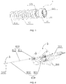
- the fastening nail includes a nail seat 11 and a spiral part 12.
- the front end of the spiral part 12 is formed as a tip 121, the rear end of the spiral part 12 is fixedly connected to the front end of the nail seat 11, and a first positioning part 110 is provided on the end surface of the rear end of the nail seat 11.
- the fastening nail 1 since the front end of the spiral part 12 is formed as a tip 121, the function of implanting the fastening nail 1 into a human organ or skin tissue can be realized by rotating the spiral part 12.
- the fastening nail 1 also includes a nail seat 11, and a first positioning part 110 is provided on the end surface of the rear end of the nail seat 11, so that the specific structure and shape of the first positioning part 110 can be provided to be suitable for a shifting fork or other conveying apparatus for inputting the fastening nail into the human body, thereby improving the tightness of the combination between the fastening nail 1 and the conveying apparatus, so as to avoid the loosening of the fastening nail 1 from the conveying apparatus.
- the spiral part 12 and the nail seat 11 are connected by means of riveting or welding.
- the spiral part 12 is formed by extending the material in a spiral shape, and the section shape of the material of the spiral part 12 is not specifically limited, for example, it may be a triangle, a circle or a rectangle.
- the nail seat 11 is in a substantially columnar structure.
- the end surface of the front end of the nail seat 11 and the rear end of the spiral part 12 are fixedly connected by means of riveting or welding.
- the number of the first positioning part 110 is not specifically limited, and may be one or multiple, for example, one first positioning part 110 is provided, and the center of the first positioning part 110 is located on the rotation axial line for rotation of the fastening nail 1, for another example, a plurality of first positioning parts 110 may be provided, and the plurality of first positioning parts 110 are distributed in an array manner on the end surface of the rear end of the nail seat 11 around the rotation axial line for rotation of the fastening nail 1.
- the above-mentioned first positioning part 110 may be formed in various specific structural forms, for example, but not limited to, the first positioning part 110 includes a positioning hole provided on the end surface of the rear end of the nail seat 11, and a positioning protrusion capable of being snapped with the positioning hole is provided at the front end of the conveying apparatus, so that the fastening nail 1 can be rotated through the positioning protrusion and the positioning hole, so as to implant the fastening nail 1 into human organ or skin tissue to assist suturing, wherein the positioning hole and the positioning protrusion are snapped with each other to ensure that the fastening nail 1 is not loosened from the conveying apparatus.
- the above-mentioned positioning holes may be one or more, and the corresponding positioning protrusions are in one-to-one correspondence to the positioning holes.
- the positioning hole may be of an ellipse or a polygon or the like, such as a triangle, a rectangle, a hexagon or a waist shape; in this embodiment, the positioning hole may be a waist-shaped hole.
- the above-mentioned first positioning part 110 may also be formed in other specific structural forms, for example, but not limited to, the above-mentioned first positioning part 110 includes a positioning protrusion provided on the end surface of the rear end of the nail seat 11, and a positioning hole capable of being snapped with the positioning protrusion is provided at the front end of the conveying apparatus, so that the fastening nail 1 can be rotated through the positioning protrusion and the positioning hole, so as to implant the fastening nail 1 into human organ or skin tissue to assist the function of suturing and the like.
- the above-mentioned positioning protrusions may be one or more, and the corresponding positioning holes are in one-to-one correspondence to the above positioning protrusions.
- the section of above-mentioned positioning protrusion may be of an ellipse or a polygon or the like, such as a triangle, a rectangle, a hexagon or a waist shape.
- an annular groove 130 may be provided on the outer peripheral surface of the nail seat 11, by tying a polymer suture for surgery on the annular groove 130, and by knotting a suture on two fastening nails 1, such that the function of locking two fastening nails 1 is achieved, this method can be applied to an operation scenario where two parts of the tissue need to be closed, and the operation is convenient, which is beneficial to shorten the operation time.
- a threaded hole 111 is provided on the end surface of the rear end of the nail seat 11, and the threaded hole 111 is configured to be matched with a conveying apparatus in a manner of screw thread.
- the first positioning part 110 includes a positioning hole provided on the end surface of the rear end of the nail seat 11, the above-mentioned threaded hole 111 is provided on the bottom wall of the positioning hole, and the threaded hole 111 extends in a direction of the rotation axial line for rotation of the fastening nail 1.
- the embodiments of the present disclosure further provide a fastening nail implanting apparatus, referring to FIG. 2 in conjunction with FIG. 1 , the fastening nail implanting apparatus is configured to implant the fastening nail 1 provided by any one of the above-mentioned optional embodiments into a human body.
- the fastening nail implanting apparatus can be considered as a conveying apparatus in the above-mentioned embodiments.
- the fastening nail implanting apparatus may include a base 200 and an implanting component (not shown in the figure), and the implanting component includes a conveying cable 310 and an anchoring handle 320. Further, the rear end of the conveying cable 310 is connected to the anchoring handle 320, and the front end of the conveying cable 310 is provided with a second positioning part 120 capable of being snapped with the first positioning part 110.
- the anchoring handle 320 is installed on the base 200, and the anchoring handle 320 is configured to be capable of driving the conveying cable 310 to rotate under a first working condition, so as to drive the fastening nail 1 snapped with the front end of the conveying cable 310 to rotate synchronously with the conveying cable 310, and driving the conveying cable 310 to release the fastening nail 1 under a second working condition.
- the first positioning part 110 includes a positioning hole provided on the end surface of the rear end of the nail seat 11
- the second positioning part 120 includes a positioning protrusion provided at the front end of conveying cable 310, and the positioning protrusion and the positioning hole on the nail seat 11 are matched with each other.
- the first positioning part 110 includes a positioning protrusion provided on the end surface of the rear end of the nail base 11
- the second positioning part 120 includes a positioning hole provided at the front end of the conveying cable 310, and the positioning hole and the positioning protrusion on the nail seat 11 are matched with each other.
- the first positioning part 110 and the second positioning part 120 are in one-to-one correspondence, and the shapes are adapted to each other, and both may be oval, triangular, rectangular, hexagonal, or waist-shaped or the like.
- the conveying cable 310 may include a casing pipe 311, a rotating cable 312 and a spring member 313, and the rotating cable 312 passes through the casing pipe 311.
- the anchoring handle 320 may include a housing 323, a first rotating knob 321 and a second rotating knob 322.
- the housing 323 is installed on the base 200, the front end of the first rotating knob 321 is installed inside the housing 323, and the first rotating knob 321 may rotate relative to the housing 323.
- a through hole penetrating through the first rotating knob 321 in a front-rear direction is provided on the first rotating knob 321, a front end of the second rotating knob 322 is arranged in a rear end of the first rotating knob 321, it should be understood that the front end of the second rotating knob 322 extends into the rear end of the first rotating knob 321 through the above-mentioned through hole, and the second rotating knob 322 may rotate relative to the first rotating knob 321; and the rear end of the first rotating knob 321 and the second rotating knob 322 are both located outside the housing.
- the rear end of the casing pipe 311 is connected with the front end of the first rotating knob 321, and a rear end of the rotating cable 312 is connected with the front end of the second rotating knob 322 through the spring member 313.
- the second positioning part 120 is provided at a front end of the casing pipe 311, a front end of the rotating cable 312 is connected with a dowel pin 314, the threaded hole 111 is provided on the end surface of the rear end of the nail seat 11.
- the first positioning part 110 in this embodiment includes a positioning hole provided on the end surface of the rear end of the nail base 11, and the above-mentioned threaded hole 111 is provided on the bottom wall of the positioning hole.
- the second positioning part 120 includes a positioning protrusion protruding from the front end of the casing pipe 311, the positioning protrusion is matched with the positioning hole of the nail seat 11, the positioning protrusion is provided with an opening communicating with the inside of the casing pipe 311, wherein the opening is configured in such a way that the dowel pin 314 penetrates outward from the interior of the casing pipe 311.
- An external thread matched with the threaded hole 111 is provided on the outer peripheral surface of the dowel pin 314.
- a rear end of the dowel pin 314 is connected to the front end of the rotating cable 312 by a conical surface 3141 whose diameter gradually increases in a direction from the dowel pin 314 to the rotating cable 312, and the other conical abutting surface (as not shown in the figure) matched with the conical surface 3141 is provided on an inner wall surface of the front end of the casing pipe 311.
- the rotating cable 312 may drive the dowel pin 314 to slide back and forth inside the casing pipe 311, and when the above-mentioned conical surface 3141 abuts against the other conical abutting surface provided on the inner wall surface of the front end of the casing pipe 311, the dowel pin 314 protrudes to the foremost end position relative to the casing pipe 311, at this time, a front end of the dowel pin 314 protrudes from the front end of the casing pipe 311 and is matched with the threaded hole 111 on the rear end of the nail seat 11.
- the dowel pin 314 is threadedly connected to the inside of the threaded hole 111 provided on the end surface of the rear end of the nail seat 11 of the fastening nail 1, and the first positioning part 110 on the nail seat 11 of the fastening nail 1 is enabled to be snapped with the second positioning part 120 of the front end of the casing pipe 311, at this time, the conical abutting surface provided on the inner wall surface of the front end of the casing pipe 311 abuts against the conical surface 3141, the spring member 313 is in a stretched state, and the rear end surface of the nail seat 11 of the fastening nail 1 abuts against the front end surface of the casing pipe 311.
- the casing pipe 311 By rotating the first rotating knob 321, the casing pipe 311 can be rotated, so that the casing pipe 311 drives the fastening nail 1 to rotate forward, so as to nail the front end of the fastening nail 1 into the human organ or skin tissue.
- the dowel pin 314 can be enabled to rotate inside the casing pipe 311 relative to the screwed fastening nail 1, so that the dowel pin 314 can be separated from the fastening nail 1.
- the dowel pin 314 is retracted to the inside of the casing pipe 311 under the action of the elastic restoring force of the spring member 313.
- the front end of the dowel pin 314 located outside the casing pipe 311 can be prevented from damaging the human body after the dowel pin 314 is separated from the fastening nail 1; and simultaneously, by providing the spring member 313, it can be ensured that before the dowel pin 314 is separated from the fastening nail 1, the dowel pin 314 always has a movement tendency of pulling the fastening nail 1 backward to make the rear end surface of the nail seat 11 of the fastening nail 1 abut against the front end surface of the casing pipe 311, so as to ensure that when the dowel pin 314 is separated from the fastening nail 1, the fastening nail 1 is sleeved on the casing pipe 311, and the casing pipe 311 controls the fastening nail 1 not to rotate during the reverse rotation of the dowel pin 314 relative to the fastening nail 1, thereby ensuring that the dowel pin 314 can be smoothly disengaged from the fastening nail 1.
- an anti-reversion part 400 is provided between the front end of the first rotating knob 321 and the housing 323, and/or, an anti-rotation part 500 is detachably connected between the first rotating knob 321 and the second rotating knob 322.
- “and/or” means that only the former or only the latter or simultaneously both the former and the latter are provided in the structure of "an anti-reversion part 400 provided between the front end of the first rotating knob 321 and the housing 323" and the structure of "an anti-rotation part 500 detachably connected between the first rotating knob 321 and the second rotating knob 322".
- the first rotating knob 321 may comprise an end connecting rod 3213, a first shaft rod 3212 and a first rotating shell 3211 connected from front to back in sequence, and the end connecting rod 3213 and the first shaft rod 3212 are mounted inside the housing 323.
- the first rotating shell 3211 is detachably connected to one end of the first shaft rod 3212, and the other end of the first shaft rod 3212 is detachably connected to the end connecting rod 3213.
- one end of the first rotating shell 3211 is in a cylindrical structure, a snapping opening is provided on the peripheral wall of the cylindrical structure thereof, the peripheral wall of one end of the first shaft rod 3212 is provided with a snapping block, and one end of the first shaft rod 3212 extends into one end of the first rotating shell 3211, and the snapping block and the snapping opening are snapped with each other.
- the other end of the first shaft rod 3212 is protrudingly provided with a protruding part along axial line thereof, and the protruding part is matched with the snapping hole at one end of the end connecting rod 3213.
- the anti-reversion part 400 may comprise a pawl part 410 and a ratchet structure 420 provided on an outer peripheral surface of the first shaft rod 3212, and a pawl of the pawl part 410 and the ratchet structure 420 are engaged with each other.
- the second rotating knob 322 includes a second shaft rod 3222 and a second rotating shell 3221 connected to the rear end of the second shaft rod 3222.
- the second shaft rod 3222 is arranged inside the first rotating shell 3211, and the rear end of the spring member 313 is connected to the front end of the second shaft rod 3222.
- the casing pipe 311 can be enabled to only follow the second rotating shell 3221 to rotate in a forward direction, in the process of operating the second rotating shell 3221 to rotate, so that the dowel pin 314 rotates in an opposite direction relative to the fastening nail 1 and thus is disengaged from the fastening nail 1, it is ensured that the casing pipe 311 does not rotate in the opposite direction to follow the second rotating shell 3221, thereby ensuring that the dowel pin 314 is smoothly separated from the fastening nail 1.
- the structure of the above anti-reversion part 400 can also be other structures, for example, the above-mentioned pawl part 410 is replaced with a pawl provided on the inner wall of the housing 323, and the pawl is enabled to be engaged with the ratchet structure 420.
- an anti-rotation part 500 is detachably connected between the first rotating knob 321 and the second rotating knob 322.
- the anti-rotation part 500 is configured to make the first rotating knob 321 and the second rotating knob 322 rotate synchronously.
- a first positioning hole can be provided on the end surface of the rear end of the first rotating knob 321
- a second positioning hole penetrating through the second rotating knob 322 in the front-rear direction can be provided on the second rotating knob 322
- one end of the anti-rotation part 500 extends into the first positioning hole after passing through the second positioning hole, so as to avoid rotation of the second rotating knob 322 relative to the first rotating knob 321, when the first rotating knob 321 is rotated to implant the fastening nail 1 into the human organ or skin tissue.
- the anti-rotation part 500 can be pulled out.
- the fastening nail implanting apparatus further may comprise an advancing mechanism 600 and a casing support 700, wherein the advancing mechanism 600 comprises an advancing handle 610, a first gear 620 and a second gear 630.
- the advancing handle 610 is fixedly connected to the casing support 700, the rotating cable 312 passes through a lumen of the casing support 700, and the front end of the first rotating knob 321 is rotatably connected to a rear end of the lumen of the casing support 700, an avoidance hole for avoiding the pawl part 410 is provided on the casing support 700.
- the first gear 620 is provided on the outer peripheral surface of the advancing handle 610
- the second gear 630 is provided on the outer peripheral surface of the end connecting rod 3213 of the first rotating knob 321
- the first gear 620 and the second gear 630 are engaged with each other
- a window for exposing the second gear 630 is provided on the casing support 700.
- the casing support 700 can be enabled to slide forward relative to the house 323, so as to prevent the casing support 700 from providing a pulling force that pulls the fastening nail 1 backward, and to ensure that the fastening nail 1 is quickly screwed into human organ or skin tissue, optionally, the thread pitch of the external thread provided on the dowel pin 314 is equal to the tooth space of the first gear 620 provided on the advancing mechanism 600, so that the distance that the casing support 700 slides forward relative to the housing 323 is equal to the distance that the fastening nail 1 is nailed into the human organ or skin tissue.
- a sealing element 3231 is also provided inside the housing 323, and the casing pipe 311 passes through the sealing element 3231, so as to prevent blood leakage.
- the fastening nail implanting apparatus further may comprise a first bending-adjustable sheathing canal mechanism 810, wherein the first bending-adjustable sheathing canal mechanism 810 may comprise a first bending-adjustable handle 811 and a first bending-adjustable sheathing canal 812, and the first bending-adjustable handle 811 is installed on the base 200 and located at front of the anchoring handle 320, the first bending-adjustable sheathing canal 812 is installed on the first bending-adjustable handle 811, and the conveying cable 310 passes through the first bending-adjustable sheathing canal 812 and the first bending-adjustable handle 811.
- the first bending-adjustable handle 811 comprises a bending-adjustable knob 8100, a bending-adjustable screw 8200 and a bending-adjustable sliding block 8300, wherein the bending-adjustable sliding block 8300 is sleeved on the bending-adjustable screw 8200 in a manner of screw thread, a bending-adjustable wire is connected between a front end of the first bending-adjustable sheathing canal 812 and the bending-adjustable sliding block 8300, and a rear end of the bending-adjustable screw 8200 is connected with the bending-adjustable knob 8100, by rotating the bending-adjustable knob 8100, the bending-adjustable screw 8200 can be enabled to be rotated, so that the bending-adjustable sliding block 8300 slides in a length direction of the bending-adjustable screw 8200, thereby tightening or releasing the bending-a
- the fastening nail implanting apparatus further may comprise a second bending-adjustable sheathing canal mechanism 820
- the second bending-adjustable sheathing canal mechanism 820 may comprise a second bending-adjustable handle 821 and a second bending-adjustable sheathing canal 822, wherein the second bending-adjustable handle 821 is installed on the base 200 and located between the first bending-adjustable handle 811 and the anchoring handle 320, and the second bending-adjustable handle 821 may slide back and forth relative to the base 200.
- the second bending-adjustable sheathing canal 822 is installed on the second bending-adjustable handle 821, and the second bending-adjustable sheathing canal 822 passes through the first bending-adjustable handle 811 and the first bending-adjustable sheathing canal 812, and the conveying cable 310 passes through the second bending-adjustable sheathing canal 822 and the second bending-adjustable handle 821.
- the bending-adjustable principle of the second bending-adjustable handle 821 is the same as that of the first bending-adjustable handle 811, thus, the second bending-adjustable handle 821 can be used to assist the first bending-adjustable handle 811 to perform secondary adjustment on the implanting angle, the first bending-adjustable handle 811 can make the implanting angle bended by 90 degrees before implantation, on this basis, and the second bending-adjustable handle 821 can be bended by 180 degrees before implantation.
- there are various specific arrangement structure for the second bending-adjustable handle 821 capable of sliding back and forth relative to the base 200 for example, but not limited to, as shown in FIG.
- the second bending-adjustable handle 821 is connected to the base 200 through a front and rear adjustment structure 1000, wherein the front and rear adjustment structure 1000 includes an adjustment knob 1100, a gear 1200, a rack 1300 and a position-limited plate 1400, the rack 1300 is provided at the bottom of the second bending-adjustable handle 821, one end of the adjustment knob 1100 is fixedly connected with a rotating shaft, and the rotating shaft passes through the position-limited long hole on the position-limited plate 1400, the gear 1200 is fixed on one end of the rotating shaft away from the adjustment knob 1100, the position-limited plate 1400 is fixed on the base 200, the rotating shaft can slide along the position-limited long hole and is located at two position-limited positions of the position-limited long hole, at one of the position-limited positions, the gear 1200 can be engaged with the rack 1300, and the rack 1300 extends in the front-rear direction, the adjustment knob 1100 is rotated, and then the second bending-adjustable handle 821 can
- the first bending-adjustable handle 811 may also be rotatably installed on the base 200 through the rotating structure 900; and/or the second bending-adjustable handle 821 may be rotatably installed on the base 200 through the rotating structure 900, wherein “and/or” means that only the former or only the latter or simultaneously both the former and the latter are provided in the structure of "the first bending-adjustable handle 811 rotatably installed on the base 200 through the rotating structure 900" and the structure of "the second bending-adjustable handle 821 rotatably installed on the base 200 through the rotating structure 900".
- the rotating structure 900 may include an upper shell 910, a lower shell 920 and a fastener 930, the lower shell 920 is fixed on the base 200, and the upper shell 910 and the lower shell 920 are connected with each other by the fastener 930, by opening the fastener 930, the bending-adjustable handle of the bending-adjustable sheathing canal mechanism can be enabled to be clamped between the upper shell 910 and the lower shell 920 or the bending-adjustable handle can be removed from a position between the upper shell 910 and the lower shell 920, and the bending-adjustable handle of the bending-adjustable sheathing canal mechanism can rotate between the upper shell 910 and the lower shell 920, so that the implanting angle can be adjusted more conveniently.
- the first bending-adjustable sheathing canal mechanism 810 further comprise a first support pipe fitting 830; and a first sealing gasket 8111 is provided inside the first bending-adjustable handle 811, and a via hole with an axial line extending in a front-rear direction is provided on the first sealing gasket 8111; a front end of the first support pipe fitting 830 is installed on a rear end of the first bending-adjustable handle 811, and the front end of the first support pipe fitting 830 is inserted into the inside of the via hole, a lumen of the first support pipe fitting 830 communicates with the first bending-adjustable sheathing canal 812, and the conveying cable 310 passes through the first bending-adjustable sheathing canal 812 and the lumen of
- the embodiments of the present disclosure also provide a medical instrument, the medical instrument comprises a fastening nail 1 and a fastening nail implanting apparatus provided in the above-mentioned embodiments, the fastening nail implanting apparatus is configured to implant the fastening nail 1 into a human body.
- the fastening nail provided in the embodiments of the present disclosure can be applied to a shifting fork or other conveying apparatuses for inputting fastening nail into the human body, so as to improve the tightness of the combination between the fastening nail and the conveying apparatus, thereby avoiding the loosening of the fastening nail from the conveying apparatus.
- the fastening nail implanting apparatus provided by the embodiments of the present disclosure is convenient to operate, and is conducive to quickly implanting the fastening nail into the human body, so as to shorten the operation time, reduce the intraoperative risk, and facilitate the rapid postoperative healing of the patient.
- the medical instrument of the embodiment of the present disclosure is not only convenient to operate, but also can improve the tightness of the combination between the fastening nail and the fastening nail implanting apparatus, avoid the loosening of the fastening nail from the fastening nail implanting apparatus, and is conducive to the rapid implantation of fastening nail into the human body.
Landscapes
- Health & Medical Sciences (AREA)
- Life Sciences & Earth Sciences (AREA)
- Surgery (AREA)
- Molecular Biology (AREA)
- Engineering & Computer Science (AREA)
- Biomedical Technology (AREA)
- Heart & Thoracic Surgery (AREA)
- Medical Informatics (AREA)
- Nuclear Medicine, Radiotherapy & Molecular Imaging (AREA)
- Animal Behavior & Ethology (AREA)
- General Health & Medical Sciences (AREA)
- Public Health (AREA)
- Veterinary Medicine (AREA)
- Rheumatology (AREA)
- Prostheses (AREA)
- Surgical Instruments (AREA)
Applications Claiming Priority (2)
| Application Number | Priority Date | Filing Date | Title |
|---|---|---|---|
| CN202010482437.9A CN111481251B (zh) | 2020-05-29 | 2020-05-29 | 紧固钉和紧固钉植入装置 |
| PCT/CN2020/122562 WO2021238036A1 (zh) | 2020-05-29 | 2020-10-21 | 紧固钉、紧固钉植入装置和医疗器械 |
Publications (4)
| Publication Number | Publication Date |
|---|---|
| EP4134014A1 true EP4134014A1 (de) | 2023-02-15 |
| EP4134014A4 EP4134014A4 (de) | 2023-09-06 |
| EP4134014B1 EP4134014B1 (de) | 2025-05-07 |
| EP4134014C0 EP4134014C0 (de) | 2025-05-07 |
Family
ID=71810649
Family Applications (1)
| Application Number | Title | Priority Date | Filing Date |
|---|---|---|---|
| EP20938315.7A Active EP4134014B1 (de) | 2020-05-29 | 2020-10-21 | Befestigungsnagel, befestigungsnagel-implantationsvorrichtung und medizinisches instrument |
Country Status (4)
| Country | Link |
|---|---|
| US (1) | US20230072622A1 (de) |
| EP (1) | EP4134014B1 (de) |
| CN (1) | CN111481251B (de) |
| WO (1) | WO2021238036A1 (de) |
Families Citing this family (8)
| Publication number | Priority date | Publication date | Assignee | Title |
|---|---|---|---|---|
| CN111481251B (zh) * | 2020-05-29 | 2024-09-24 | 科瑞迈吉(苏州)医疗科技有限公司 | 紧固钉和紧固钉植入装置 |
| CN112891024B (zh) * | 2021-01-14 | 2025-08-08 | 上海汇禾医疗科技有限公司 | 锚定器械 |
| CN112773434A (zh) * | 2021-03-10 | 2021-05-11 | 上海汇禾医疗科技有限公司 | 锚定器械 |
| CN114617593A (zh) * | 2022-04-22 | 2022-06-14 | 上海以心医疗器械有限公司 | 一种锚钉装置及锚钉输送器 |
| CN116327285B (zh) * | 2023-03-13 | 2026-03-20 | 北京天助畅运医疗技术股份有限公司 | 软组织固定手术器械 |
| CN116269941B (zh) | 2023-05-11 | 2023-08-08 | 科瑞迈吉(北京)医疗科技有限公司 | 环缩力单点可调的瓣膜缩环手术系统 |
| CN119700225B (zh) * | 2024-11-25 | 2025-09-23 | 科瑞迈吉(苏州)医疗科技有限公司 | 一种打钉调弯管控制装置、打钉控制组件及输送系统 |
| CN121015257B (zh) * | 2025-10-30 | 2026-02-06 | 上海汇禾医疗器械有限公司 | 一种可调弯鞘控制系统和锚定系统 |
Family Cites Families (19)
| Publication number | Priority date | Publication date | Assignee | Title |
|---|---|---|---|---|
| US8858565B1 (en) * | 2008-05-08 | 2014-10-14 | Cayenne Medical, Inc. | Inserter for soft tissue or bone-to-bone fixation device and methods |
| WO2013069019A2 (en) * | 2011-11-08 | 2013-05-16 | Valtech Cardio, Ltd. | Controlled steering functionality for implant-delivery tool |
| US8523881B2 (en) * | 2010-07-26 | 2013-09-03 | Valtech Cardio, Ltd. | Multiple anchor delivery tool |
| EP2506777B1 (de) * | 2009-12-02 | 2020-11-25 | Valtech Cardio, Ltd. | Kombination von einer Spulenanordnung mit helikalem Anker und einem Verabreichungswerkzeug zur Implantation derselben |
| EP3730066A1 (de) * | 2012-10-23 | 2020-10-28 | Valtech Cardio, Ltd. | Perkutane gewebeankertechniken |
| CN105007832B (zh) * | 2013-01-09 | 2018-01-23 | 4科技有限公司 | 组织锚状物设备 |
| US9615830B2 (en) * | 2013-11-08 | 2017-04-11 | C.R. Bard, Inc. | Surgical fastener |
| US9445814B2 (en) * | 2013-11-08 | 2016-09-20 | C.R. Bard, Inc. | Surgical fastener |
| EP3288496B1 (de) * | 2015-04-30 | 2024-05-29 | Edwards Lifesciences Innovation (Israel) Ltd. | Technologien für die annuloplastie |
| US10478303B2 (en) * | 2017-03-13 | 2019-11-19 | Polares Medical Inc. | Device, system, and method for transcatheter treatment of valvular regurgitation |
| EP3541298B1 (de) * | 2017-06-09 | 2021-08-18 | Signum Surgical Limited | Implantat zum verschliessen einer öffnung in einem gewebe |
| CN111107810B (zh) * | 2017-07-28 | 2022-06-07 | 波士顿科学国际有限公司 | 具有直接驱动机构的手柄 |
| CN109223076A (zh) * | 2018-09-28 | 2019-01-18 | 北京市春立正达医疗器械股份有限公司 | 免打结锚钉及其植入装置 |
| CN210447086U (zh) * | 2019-01-31 | 2020-05-05 | 上海诺强医疗科技有限公司 | 瓣环收缩器 |
| CN210931596U (zh) * | 2019-09-04 | 2020-07-07 | 江苏三联星海医疗器械股份有限公司 | 一种软组织修复补片用记忆合金固定钉 |
| CN111568605A (zh) * | 2020-05-29 | 2020-08-25 | 迈特锐吉(北京)医疗科技有限公司 | 修复组件和修复组件植入装置 |
| CN111481251B (zh) * | 2020-05-29 | 2024-09-24 | 科瑞迈吉(苏州)医疗科技有限公司 | 紧固钉和紧固钉植入装置 |
| CN111481250B (zh) * | 2020-05-29 | 2024-09-24 | 科瑞迈吉(苏州)医疗科技有限公司 | 修复组件植入手柄 |
| CN212326481U (zh) * | 2020-05-29 | 2021-01-12 | 迈特锐吉(北京)医疗科技有限公司 | 紧固钉和紧固钉植入装置 |
-
2020
- 2020-05-29 CN CN202010482437.9A patent/CN111481251B/zh active Active
- 2020-10-21 WO PCT/CN2020/122562 patent/WO2021238036A1/zh not_active Ceased
- 2020-10-21 EP EP20938315.7A patent/EP4134014B1/de active Active
-
2022
- 2022-11-17 US US18/056,435 patent/US20230072622A1/en not_active Abandoned
Also Published As
| Publication number | Publication date |
|---|---|
| EP4134014B1 (de) | 2025-05-07 |
| EP4134014A4 (de) | 2023-09-06 |
| CN111481251A (zh) | 2020-08-04 |
| CN111481251B (zh) | 2024-09-24 |
| US20230072622A1 (en) | 2023-03-09 |
| EP4134014C0 (de) | 2025-05-07 |
| WO2021238036A1 (zh) | 2021-12-02 |
Similar Documents
| Publication | Publication Date | Title |
|---|---|---|
| US20230072622A1 (en) | Fastening nail, fastening nail implanting apparatus and medical instrument | |
| US12318093B2 (en) | Polymer overmolded bariatric clamp and method of installing | |
| EP3351187B1 (de) | Endoskopbehandlungsinstrument | |
| US11723786B2 (en) | Bariatric clamp with suture portions, magnetic inserts and curvature | |
| US10357253B2 (en) | Endoscopic treatment tool | |
| US10010326B2 (en) | Endoscopic treatment tool | |
| EP4129235B1 (de) | Reparaturanordnung und implantationsvorrichtung für reparaturanordnung | |
| US7344495B2 (en) | Surgical retractor apparatus for use with a surgical port | |
| US7195592B2 (en) | Surgical retractor apparatus for use with a surgical port | |
| EP3351189B1 (de) | Endoskopisches behandlungsinstrument | |
| US5653718A (en) | Cannula anchoring system | |
| JP6130302B2 (ja) | 組織壁の刺し傷を封止するシステム | |
| US20200060725A1 (en) | Tissue-fastening tool indwelling system and method for indwelling tissue-fastening tool | |
| US9101345B2 (en) | Surgical guide and tissue anchor | |
| US9572685B2 (en) | Instrument for implanting implant device | |
| EP3222222A1 (de) | Drehsteuerungsmechanismus und chirurgisches instrument mit drehsteuermechanismus | |
| JP2011062544A (ja) | 外科用手接近装置 | |
| JP2012000443A (ja) | 「自動経管組織目標設定固定デバイス及び方法」 | |
| CN114305551B (zh) | 医用锁扣及医用锁结装置 | |
| CN212326481U (zh) | 紧固钉和紧固钉植入装置 | |
| US12161338B2 (en) | Suture-free clasp for vascular anastomosis | |
| US10709441B2 (en) | Suture body and suture system | |
| CN116849786A (zh) | 半月板缝合装置、自恢复可弯缝合钉和半月板缝合系统 | |
| CN117814955A (zh) | 收线装置及经导管瓣环成形系统 |
Legal Events
| Date | Code | Title | Description |
|---|---|---|---|
| STAA | Information on the status of an ep patent application or granted ep patent |
Free format text: STATUS: THE INTERNATIONAL PUBLICATION HAS BEEN MADE |
|
| PUAI | Public reference made under article 153(3) epc to a published international application that has entered the european phase |
Free format text: ORIGINAL CODE: 0009012 |
|
| STAA | Information on the status of an ep patent application or granted ep patent |
Free format text: STATUS: REQUEST FOR EXAMINATION WAS MADE |
|
| 17P | Request for examination filed |
Effective date: 20221111 |
|
| AK | Designated contracting states |
Kind code of ref document: A1 Designated state(s): AL AT BE BG CH CY CZ DE DK EE ES FI FR GB GR HR HU IE IS IT LI LT LU LV MC MK MT NL NO PL PT RO RS SE SI SK SM TR |
|
| STAA | Information on the status of an ep patent application or granted ep patent |
Free format text: STATUS: EXAMINATION IS IN PROGRESS |
|
| A4 | Supplementary search report drawn up and despatched |
Effective date: 20230808 |
|
| DAV | Request for validation of the european patent (deleted) | ||
| DAX | Request for extension of the european patent (deleted) | ||
| RIC1 | Information provided on ipc code assigned before grant |
Ipc: A61B 17/068 20060101ALI20230802BHEP Ipc: A61B 17/064 20060101AFI20230802BHEP |
|
| 17Q | First examination report despatched |
Effective date: 20230821 |
|
| GRAP | Despatch of communication of intention to grant a patent |
Free format text: ORIGINAL CODE: EPIDOSNIGR1 |
|
| STAA | Information on the status of an ep patent application or granted ep patent |
Free format text: STATUS: GRANT OF PATENT IS INTENDED |
|
| INTG | Intention to grant announced |
Effective date: 20250127 |
|
| RAP3 | Party data changed (applicant data changed or rights of an application transferred) |
Owner name: CREATIVE MEDTECH (SUZHOU) CO., LTD |
|
| GRAS | Grant fee paid |
Free format text: ORIGINAL CODE: EPIDOSNIGR3 |
|
| GRAA | (expected) grant |
Free format text: ORIGINAL CODE: 0009210 |
|
| STAA | Information on the status of an ep patent application or granted ep patent |
Free format text: STATUS: THE PATENT HAS BEEN GRANTED |
|
| AK | Designated contracting states |
Kind code of ref document: B1 Designated state(s): AL AT BE BG CH CY CZ DE DK EE ES FI FR GB GR HR HU IE IS IT LI LT LU LV MC MK MT NL NO PL PT RO RS SE SI SK SM TR |
|
| REG | Reference to a national code |
Ref country code: GB Ref legal event code: FG4D |
|
| REG | Reference to a national code |
Ref country code: CH Ref legal event code: EP |
|
| REG | Reference to a national code |
Ref country code: IE Ref legal event code: FG4D |
|
| U01 | Request for unitary effect filed |
Effective date: 20250507 |
|
| U07 | Unitary effect registered |
Designated state(s): AT BE BG DE DK EE FI FR IT LT LU LV MT NL PT RO SE SI Effective date: 20250513 |
|
| PG25 | Lapsed in a contracting state [announced via postgrant information from national office to epo] |
Ref country code: ES Free format text: LAPSE BECAUSE OF FAILURE TO SUBMIT A TRANSLATION OF THE DESCRIPTION OR TO PAY THE FEE WITHIN THE PRESCRIBED TIME-LIMIT Effective date: 20250507 |
|
| PG25 | Lapsed in a contracting state [announced via postgrant information from national office to epo] |
Ref country code: GR Free format text: LAPSE BECAUSE OF FAILURE TO SUBMIT A TRANSLATION OF THE DESCRIPTION OR TO PAY THE FEE WITHIN THE PRESCRIBED TIME-LIMIT Effective date: 20250808 Ref country code: NO Free format text: LAPSE BECAUSE OF FAILURE TO SUBMIT A TRANSLATION OF THE DESCRIPTION OR TO PAY THE FEE WITHIN THE PRESCRIBED TIME-LIMIT Effective date: 20250807 |
|
| PG25 | Lapsed in a contracting state [announced via postgrant information from national office to epo] |
Ref country code: PL Free format text: LAPSE BECAUSE OF FAILURE TO SUBMIT A TRANSLATION OF THE DESCRIPTION OR TO PAY THE FEE WITHIN THE PRESCRIBED TIME-LIMIT Effective date: 20250507 |
|
| PG25 | Lapsed in a contracting state [announced via postgrant information from national office to epo] |
Ref country code: HR Free format text: LAPSE BECAUSE OF FAILURE TO SUBMIT A TRANSLATION OF THE DESCRIPTION OR TO PAY THE FEE WITHIN THE PRESCRIBED TIME-LIMIT Effective date: 20250507 |
|
| PG25 | Lapsed in a contracting state [announced via postgrant information from national office to epo] |
Ref country code: RS Free format text: LAPSE BECAUSE OF FAILURE TO SUBMIT A TRANSLATION OF THE DESCRIPTION OR TO PAY THE FEE WITHIN THE PRESCRIBED TIME-LIMIT Effective date: 20250807 |
|
| PG25 | Lapsed in a contracting state [announced via postgrant information from national office to epo] |
Ref country code: IS Free format text: LAPSE BECAUSE OF FAILURE TO SUBMIT A TRANSLATION OF THE DESCRIPTION OR TO PAY THE FEE WITHIN THE PRESCRIBED TIME-LIMIT Effective date: 20250907 |
|
| U20 | Renewal fee for the european patent with unitary effect paid |
Year of fee payment: 6 Effective date: 20251023 |
|
| PG25 | Lapsed in a contracting state [announced via postgrant information from national office to epo] |
Ref country code: SM Free format text: LAPSE BECAUSE OF FAILURE TO SUBMIT A TRANSLATION OF THE DESCRIPTION OR TO PAY THE FEE WITHIN THE PRESCRIBED TIME-LIMIT Effective date: 20250507 |
|
| PG25 | Lapsed in a contracting state [announced via postgrant information from national office to epo] |
Ref country code: CZ Free format text: LAPSE BECAUSE OF FAILURE TO SUBMIT A TRANSLATION OF THE DESCRIPTION OR TO PAY THE FEE WITHIN THE PRESCRIBED TIME-LIMIT Effective date: 20250507 |
|
| PG25 | Lapsed in a contracting state [announced via postgrant information from national office to epo] |
Ref country code: SK Free format text: LAPSE BECAUSE OF FAILURE TO SUBMIT A TRANSLATION OF THE DESCRIPTION OR TO PAY THE FEE WITHIN THE PRESCRIBED TIME-LIMIT Effective date: 20250507 |
|
| PLBE | No opposition filed within time limit |
Free format text: ORIGINAL CODE: 0009261 |
|
| STAA | Information on the status of an ep patent application or granted ep patent |
Free format text: STATUS: NO OPPOSITION FILED WITHIN TIME LIMIT |
|
| REG | Reference to a national code |
Ref country code: CH Ref legal event code: L10 Free format text: ST27 STATUS EVENT CODE: U-0-0-L10-L00 (AS PROVIDED BY THE NATIONAL OFFICE) Effective date: 20260318 |
|
| 26N | No opposition filed |
Effective date: 20260210 |