EP4134037A1 - Diagnose-/behandlungshilfsroboter, diagnose-/behandlungshilfsrobotersystem und diagnose-/behandlungshilfsverfahren - Google Patents
Diagnose-/behandlungshilfsroboter, diagnose-/behandlungshilfsrobotersystem und diagnose-/behandlungshilfsverfahren Download PDFInfo
- Publication number
- EP4134037A1 EP4134037A1 EP21784597.3A EP21784597A EP4134037A1 EP 4134037 A1 EP4134037 A1 EP 4134037A1 EP 21784597 A EP21784597 A EP 21784597A EP 4134037 A1 EP4134037 A1 EP 4134037A1
- Authority
- EP
- European Patent Office
- Prior art keywords
- diagnosis
- instrument
- auxiliary
- treatment
- treatment support
- Prior art date
- Legal status (The legal status is an assumption and is not a legal conclusion. Google has not performed a legal analysis and makes no representation as to the accuracy of the status listed.)
- Pending
Links
Images









Classifications
-
- A—HUMAN NECESSITIES
- A61—MEDICAL OR VETERINARY SCIENCE; HYGIENE
- A61B—DIAGNOSIS; SURGERY; IDENTIFICATION
- A61B34/00—Computer-aided surgery; Manipulators or robots specially adapted for use in surgery
- A61B34/30—Surgical robots
- A61B34/37—Leader-follower robots
-
- A—HUMAN NECESSITIES
- A61—MEDICAL OR VETERINARY SCIENCE; HYGIENE
- A61B—DIAGNOSIS; SURGERY; IDENTIFICATION
- A61B5/00—Measuring for diagnostic purposes; Identification of persons
- A61B5/15—Devices for taking samples of blood
- A61B5/150007—Details
-
- A—HUMAN NECESSITIES
- A61—MEDICAL OR VETERINARY SCIENCE; HYGIENE
- A61B—DIAGNOSIS; SURGERY; IDENTIFICATION
- A61B90/00—Instruments, implements or accessories specially adapted for surgery or diagnosis and not covered by any of the groups A61B1/00 - A61B50/00, e.g. for luxation treatment or for protecting wound edges
- A61B90/36—Image-producing devices or illumination devices not otherwise provided for
- A61B90/37—Surgical systems with images on a monitor during operation
-
- A—HUMAN NECESSITIES
- A61—MEDICAL OR VETERINARY SCIENCE; HYGIENE
- A61B—DIAGNOSIS; SURGERY; IDENTIFICATION
- A61B90/00—Instruments, implements or accessories specially adapted for surgery or diagnosis and not covered by any of the groups A61B1/00 - A61B50/00, e.g. for luxation treatment or for protecting wound edges
- A61B90/50—Supports for surgical instruments, e.g. articulated arms
-
- A—HUMAN NECESSITIES
- A61—MEDICAL OR VETERINARY SCIENCE; HYGIENE
- A61B—DIAGNOSIS; SURGERY; IDENTIFICATION
- A61B10/00—Instruments for taking body samples for diagnostic purposes; Other methods or instruments for diagnosis, e.g. for vaccination diagnosis, sex determination or ovulation-period determination; Throat striking implements
- A61B10/0045—Devices for taking samples of body liquids
-
- A—HUMAN NECESSITIES
- A61—MEDICAL OR VETERINARY SCIENCE; HYGIENE
- A61B—DIAGNOSIS; SURGERY; IDENTIFICATION
- A61B10/00—Instruments for taking body samples for diagnostic purposes; Other methods or instruments for diagnosis, e.g. for vaccination diagnosis, sex determination or ovulation-period determination; Throat striking implements
- A61B10/0045—Devices for taking samples of body liquids
- A61B10/0051—Devices for taking samples of body liquids for taking saliva or sputum samples
-
- A—HUMAN NECESSITIES
- A61—MEDICAL OR VETERINARY SCIENCE; HYGIENE
- A61B—DIAGNOSIS; SURGERY; IDENTIFICATION
- A61B10/00—Instruments for taking body samples for diagnostic purposes; Other methods or instruments for diagnosis, e.g. for vaccination diagnosis, sex determination or ovulation-period determination; Throat striking implements
- A61B10/02—Instruments for taking cell samples or for biopsy
- A61B2010/0216—Sampling brushes
-
- A—HUMAN NECESSITIES
- A61—MEDICAL OR VETERINARY SCIENCE; HYGIENE
- A61B—DIAGNOSIS; SURGERY; IDENTIFICATION
- A61B34/00—Computer-aided surgery; Manipulators or robots specially adapted for use in surgery
- A61B34/30—Surgical robots
- A61B2034/305—Details of wrist mechanisms at distal ends of robotic arms
- A61B2034/306—Wrists with multiple vertebrae
-
- A—HUMAN NECESSITIES
- A61—MEDICAL OR VETERINARY SCIENCE; HYGIENE
- A61B—DIAGNOSIS; SURGERY; IDENTIFICATION
- A61B5/00—Measuring for diagnostic purposes; Identification of persons
- A61B5/15—Devices for taking samples of blood
- A61B5/150007—Details
- A61B5/150015—Source of blood
- A61B5/15003—Source of blood for venous or arterial blood
-
- A—HUMAN NECESSITIES
- A61—MEDICAL OR VETERINARY SCIENCE; HYGIENE
- A61B—DIAGNOSIS; SURGERY; IDENTIFICATION
- A61B90/00—Instruments, implements or accessories specially adapted for surgery or diagnosis and not covered by any of the groups A61B1/00 - A61B50/00, e.g. for luxation treatment or for protecting wound edges
- A61B90/10—Instruments, implements or accessories specially adapted for surgery or diagnosis and not covered by any of the groups A61B1/00 - A61B50/00, e.g. for luxation treatment or for protecting wound edges for stereotaxic surgery, e.g. frame-based stereotaxis
- A61B90/11—Instruments, implements or accessories specially adapted for surgery or diagnosis and not covered by any of the groups A61B1/00 - A61B50/00, e.g. for luxation treatment or for protecting wound edges for stereotaxic surgery, e.g. frame-based stereotaxis with guides for needles or instruments, e.g. arcuate slides or ball joints
- A61B90/13—Instruments, implements or accessories specially adapted for surgery or diagnosis and not covered by any of the groups A61B1/00 - A61B50/00, e.g. for luxation treatment or for protecting wound edges for stereotaxic surgery, e.g. frame-based stereotaxis with guides for needles or instruments, e.g. arcuate slides or ball joints guided by light, e.g. laser pointers
-
- A—HUMAN NECESSITIES
- A61—MEDICAL OR VETERINARY SCIENCE; HYGIENE
- A61B—DIAGNOSIS; SURGERY; IDENTIFICATION
- A61B90/00—Instruments, implements or accessories specially adapted for surgery or diagnosis and not covered by any of the groups A61B1/00 - A61B50/00, e.g. for luxation treatment or for protecting wound edges
- A61B90/36—Image-producing devices or illumination devices not otherwise provided for
- A61B90/361—Image-producing devices, e.g. surgical cameras
Definitions
- the present disclosure relates to a diagnosis/treatment support robot, a diagnosis/treatment support robot system, and a diagnosis/treatment support method.
- PTL 1 discloses a blood collecting system in which a robot travels to supply to a blood collection base a blood collecting vessel storage tray which is for a patient in a room and is prepared by a blood collecting vessel preparation device.
- the present disclosure was made to solve the above problems, and an object of the present disclosure is to provide a diagnosis/treatment support robot, a diagnosis/treatment support robot system, and a diagnosis/treatment support method, each of which performs at least either one of an auxiliary practice of a diagnosis or an auxiliary practice of a treatment in place of a medical worker, and with this, prevents the medical worker from being infected with an infectious disease.
- a diagnosis/treatment support robot includes a surgical manipulator that is remotely manipulated by an operator.
- the surgical manipulator includes a robotic arm.
- the robotic arm includes an instrument mount at a tip thereof.
- a surgical instrument for surgery of a patient is attached to the instrument mount.
- An auxiliary instrument is attachable to the instrument mount.
- the auxiliary instrument is an instrument other than the surgical instrument.
- the auxiliary instrument is an instrument for at least either one of an auxiliary practice of a diagnosis of an infectious disease for a target person or an auxiliary practice of a treatment of the infectious disease for the target person.
- the auxiliary instrument can be attached to the instrument mount, and the operator can manipulate the surgical manipulator.
- the diagnosis/treatment support robot can perform at least either one of the diagnosis or the treatment in place of a medical worker.
- the surgical manipulator can perform surgery of a patient by precise operation. Therefore, the auxiliary practice of the diagnosis or the auxiliary practice of the treatment can be appropriately performed even when it is slightly complex.
- the surgical manipulator may be located in an isolation area that isolates a person who is suspected to be infected (hereinafter referred to as a "suspected infected person") or an infected person (hereinafter such the isolation area may be simply referred to as the "isolation area"), and the operator may be located in a normal area that is not isolated and remotely manipulates the surgical manipulator. With this, the operator can be prevented from being infected with the infectious disease. As a result, the medical worker can be prevented from being infected with the infectious disease.
- the prevalence of the infectious disease is intermittent. Therefore, when the infectious disease is not prevalent, the surgical instrument is attached to the robotic arm, and the diagnosis/treatment support robot is used as a surgical robot as it should be used. Thus, the diagnosis/treatment support robot can be effectively used.
- a diagnosis/treatment support robot system includes: the above diagnosis/treatment support robot; and the auxiliary instrument.
- a diagnosis/treatment instrument can be attached to the surgical manipulator of the diagnosis/treatment support robot. With this, at least either one of the diagnosis or the treatment can be performed by using the surgical manipulator.
- a diagnosis/treatment support robot system includes: the above diagnosis/treatment support robot; a remote controller by which the operator remotely manipulates the surgical manipulator of the diagnosis/treatment support robot; and a first imager that is attached to the instrument mount of the robotic arm of the surgical manipulator and takes an image of a state of an area where the diagnosis/treatment for the target person is performed.
- the surgical manipulator includes a plurality of the robotic arms.
- the robotic arms includes: a diagnosis/treatment arm including the instrument mount to which the auxiliary instrument is attached; and an imaging arm including the instrument mount to which the first imager is attached.
- the remote controller includes: a second display that displays the image of the state of the area which is taken by the first imager; and a second imager that takes an image of the operator.
- the surgical manipulator further includes a first display that displays the image of the operator which is taken by the second imager.
- the first imager attached to the instrument mount of the robotic arm of the surgical manipulator can take the image of the state of the area (hereinafter referred to as a "diagnosis/treatment area") where the diagnosis/treatment for the target person is performed, and the taken image of the state of the diagnosis/treatment area can be displayed on the second display of the remote controller.
- diagnosis/treatment area the state of the area
- the auxiliary practice of the diagnosis or the auxiliary practice of the treatment can be appropriately performed.
- the first imager is attached to the robotic arm of the surgical manipulator, the operator can freely manipulate the first imager to watch what the operator wants to watch in such a manner that the operator wants to watch.
- the first display of the surgical manipulator can display the image of the operator taken by the second imager of the remote controller. Therefore, the target person can know the states (facial expressions, attitudes, etc.) of the operator. As a result, the target person can relax. As above, the operator and the target person can communicate with each other by the video image.
- a diagnosis/treatment support method is a diagnosis/treatment support method using a diagnosis/treatment support robot.
- the diagnosis/treatment support robot includes a surgical manipulator that is remotely manipulated by an operator.
- the surgical manipulator includes a robotic arm.
- the robotic arm includes an instrument mount at a tip thereof.
- a surgical instrument for surgery of a patient is attached to the instrument mount.
- An auxiliary instrument is attachable to the instrument mount.
- the auxiliary instrument is an instrument other than the surgical instrument.
- the auxiliary instrument is an instrument for at least either one of an auxiliary practice of a diagnosis of an infectious disease for a target person or an auxiliary practice of a treatment of the infectious disease for the target person.
- the diagnosis/treatment support method includes attaching the auxiliary instrument instead of the surgical instrument to the instrument mount.
- the surgical manipulator can perform at least either one of the auxiliary practice of the diagnosis or the auxiliary practice of the treatment in place of the medical worker. With this, the medical worker can be prevented from being infected with the infectious disease.
- the present disclosure achieves an effect of being able to provide a diagnosis/treatment support robot, a diagnosis/treatment support robot system, and a diagnosis/treatment support method, each of which can perform at least either one of an auxiliary practice of a diagnosis or an auxiliary practice of a treatment in place of a medical worker, and with this, can prevent the medical worker from being infected with an infectious disease.
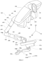
- FIG. 1 is an external view showing one example of a hardware configuration of a diagnosis/treatment support robot system according to the present disclosure.
- FIG. 2 is an external view showing one example of the configuration of a surgical manipulator of FIG. 1 .
- a display 173 of FIG. 1 is not shown.
- a diagnosis/treatment support robot system 1 of the present embodiment includes a diagnosis/treatment support robot 10 and a remote controller 20.
- the diagnosis/treatment support robot 10 is disposed in an isolation area where an infected person or a suspected infected person is isolated.
- the isolation area is, for example, a depressurized room.
- the remote controller 20 is disposed in a normal area that is not isolated.
- the diagnosis/treatment support robot 10 includes a surgical manipulator 6 and a cart 70.
- the cart 70 includes a main body 70a, front wheels 141A, and a rear wheel 141b.
- the front wheels 141A are driving wheels, and the rear wheel is a steered wheel.
- the front wheels are driven by a driving source (not shown; for example, a motor) incorporated in the main body 70a.
- the rear wheel is steered by the driving source. With this, the cart 70 can autonomously travel.
- the main body 70a houses a first controller 31.
- the operations of the front wheels 141A and the rear wheel 141b are controlled by the first controller 31. With this, the cart 70 can automatically travel.
- the first controller 31 controls the operations of the front wheels 141A and the rear wheel 141b in accordance with a stored travel program or a travel command from the remote controller 20 as will be described later.
- the first controller 31 controls the front wheels 141A and the rear wheel 141b in accordance with the travel program. With this, the cart 70 moves from the normal area to the isolation area through a preset movement route.
- the surgical manipulator 6 is not especially limited, and a known surgical manipulator may be used as the surgical manipulator 6.
- the surgical manipulator 6 includes a positioner 7 and robotic arms 130.
- the positioner 7 positions the robotic arms 130 at positions where the robotic arms 130 easily perform work for a target person (a patient in the case of surgery; an infected person or a suspected infected person in the case of a diagnosis or a treatment).
- a target person a patient in the case of surgery; an infected person or a suspected infected person in the case of a diagnosis or a treatment.
- the positioner 7 includes a vertical articulated robot.
- the positioner 7 includes: first to sixth positioner links 111 to 116 arranged from a base 117 toward a tip of the positioner 7; and seven joints JP1 to JP7 coupling the first to sixth positioner links 111 to 116 in order.
- An arm base 120 is disposed at the tip of the positioner 7.
- the base 117 is fixed to an upper surface of the main body 70a of the cart 70.
- the arm base 120 functions as a platform of the robotic arms 130.
- the robotic arms 130 are coupled to the arm base 120.
- the number of robotic arms 130 is not especially limited. Herein, the number of robotic arms 130 is four.
- a reference sign "130" is used.
- the surgical manipulator 6 includes first to fourth robotic arms 130A to 130D.
- FIG. 2 shows one robotic arm 130 as a representative of the four robotic arms 130A to 130D.
- a reference sign G represents a floor surface in the isolation area.
- a reference sign OT represents a bed.
- a reference sign P represents a target person.
- FIG. 2 shows that: the diagnosis/treatment support robot 10 is at a position suitable for the diagnosis and/or the treatment of the target person P who lies on his/her back on the bed OT; and an auxiliary practice of the diagnosis and/or an auxiliary practice of the treatment for the target person P are about to be performed by the surgical manipulator 6.
- the arm base 120 is coupled to the sixth positioner link 116 through a first attaching portion 121 so as to be rotatable about a rotation axis SP1 of the twist rotary joint JP7.
- each of the robotic arms 130 is coupled to the arm base 120 through a second attaching portion 122.
- the robotic arm 130 includes an articulated robotic arm.
- the robotic arm 130 includes: first to sixth arm links 131 to 136 arranged from a base 138 toward a tip of the robotic arm 130; and seven joints JA1 to JA7 coupling the first to sixth arm links 131 to 136 in order.
- An instrument mount 137 is coupled to the tip of the robotic arm 130.
- the base 138 is coupled to the second attaching portion 122 of the arm base 120 so as to be rotatable about a predetermined twisting rotation axis SA1.
- the predetermined twisting rotation axis SA1 is set to intersect with the rotation axis SP1 of the twist rotary joint JP7 at a predetermined angle when viewed from a longitudinal direction of the arm base 120.
- An auxiliary instrument 150 is attached to the instrument mount 137.
- FIG. 3 is an external view showing one example of the configuration of the robotic arm 130 of FIG. 2 and one example of the configuration of the auxiliary instrument 150 of FIG. 2 .
- the display 173 of FIG. 1 is not shown.
- the robotic arm 130 can freely move the instrument mount 137 in three directions XA, YA, and ZA in three dimensions and can freely change the posture of the instrument mount 137 in the three directions XA, YA, and ZA in three dimensions.
- the auxiliary instrument 150 has four (or more) degrees of freedom of movement of the auxiliary instrument 150.
- the auxiliary instrument 150 is attached to the instrument mount 137, and then the instrument mount 137 allows the auxiliary instrument 150 to operate in four (or more) degrees of freedom of movement thereof. Therefore, the auxiliary instrument 150 can perform complex work.
- the instrument mount 137 includes an attaching portion 137a, a main body 137b, and a movable body 137c.
- the attaching portion 137a projects from one side of the main body 137b and is coupled to the sixth arm link 136 of the robotic arm 130 so as to be rotatable about a rotation axis (not shown) of the seventh joint JT7 that is a bending rotary joint.
- the main body 137b moves the movable body 137c in directions D1A and D1B orthogonal to the rotation axis of the seventh joint JT7.
- the auxiliary instrument 150 is coupled to the movable body 137c. Therefore, the instrument mount 137 moves the auxiliary instrument 150 in the directions D1A and D1B.
- FIG. 4 is a vertical sectional view showing one example of the configuration of the movable body 137c of the instrument mount 137 of FIG. 3 .
- FIG. 4 shows a vertical section in a longitudinal direction of the movable body 137c of FIG. 3 .
- the movable body 137c has a hollow box shape.
- a motor (for example, a servomotor) M and an encoder E as a rotation angle detector coupled to a main shaft R of the motor M are disposed in the movable body 137c.
- a cylindrical recess 50 is formed at one end of the movable body 137c on a side surface of the movable body 137c which is located at an opposite side of the main body 137b.
- a central axis of the recess 50 extends in a direction orthogonal to the rotation axis of the seventh joint JT7 and the directions D1A and D1B.
- An opening 51 is formed in the middle of a bottom surface of the recess 50.
- the motor M and the encoder E are disposed such that the main shaft R projects through the opening 51 to an outside.
- the motor M is arranged such that the main shaft R coincides with the central axis of the recess 50.
- a female coupling 61 is disposed at a tip of the main shaft R.
- a fitting recess 61a having a distinct cross-sectional shape is formed on a tip surface of the female coupling 61. Examples of the distinct cross-sectional shape include a minus shape, a plus shape, a square shape, and a hexagonal shape.
- Locks 52 are disposed at at least one pair of opposing portions on an inner peripheral surface of the recess 50.
- Each of the locks 52 includes a locking pin 51a that can protrude or retract in a radial direction of the recess 50.
- a tip of the locking pin 51a has a semi-spherical shape.
- the locking pin 51a is biased in the radial direction of the recess 50 by an elastic structure (not shown).
- the auxiliary instrument 150 includes an attaching portion 150d, and the attaching portion 150d includes a cylindrical projection 60 whose tip is open.
- the projection 60 has a shape that is fitted into the recess 50. Therefore, a central axis of the projection 60 coincides with the central axis of the recess 50.
- An opening 66 is formed in the middle of a bottom surface of the projection 60.
- a driving shaft 63 is disposed so as to extend from an inside of the projection 60 through the opening 66 to an inside of the attaching portion 150d.
- the driving shaft 63 is rotatably supported by a bearing 64 disposed in at the opening 66 such that a rotation axis of the driving shaft 63 coincides with a rotation axis of the main shaft R of the motor M.
- a male coupling 62 is disposed at a tip of the driving shaft 63.
- a fitting projection 62a fitted into the fitting recess 61a of the female coupling 61 is formed on a tip surface of the male coupling 62.
- the male coupling 62 is located such that when the projection 60 is fittingly inserted deep into the recess 50, the fitting projection 62a is inserted and just fitted into the fitting recess 61a of the female coupling 61.
- Engagers 67 are disposed at at least one pair of portions on an outer periphery of the projection 60, the pair of portions facing in directions opposite to each other.
- Each of the engagers 67 is a recess that is recessed in a radial direction of the projection 60 in a semi-spherical shape.
- the engagers 67 are located such that when the projection 60 is fittingly inserted deep into the recess 50, the locking pins 51a of the recess 50 just protrude into the engagers 67, and thus, the projection 60 is locked to the recess 50.
- a reference sign 65 represents a seal structure that seals an inside of the attaching portion 150d.
- the projection 60 of the auxiliary instrument 150 is pushed deep into the recess 50 of the movable body 137c. With this, the locking pins 51a in the recess 50 protrude toward (enter into) the engagers 67 of the projection 60 to lock the projection 60 to the recess 50.
- the auxiliary instrument 150 is attached to the movable body 137c.
- rotational power of the driving shaft 63 is transmitted to a claw holding body 150b of the auxiliary instrument 150 through a suitable power transmitting structure.
- the projection 60 When attaching an imager 151 (see FIG. 1 ) to the movable body 137c, the projection 60 is attached to the imager 151. Moreover, the female coupling 61 of the recess 50 and the male coupling 62 of the projection 60 are omitted, and instead of these, electric contacts through which control signals, data, and the like of the imager 151 are transmitted are disposed at the recess 50 and the projection 60.
- the recess 50 and the projection 60 are configured in accordance with the type of the surgical instrument 180.
- the recess 50 and the projection 60 are configured in the same manner as above.
- the surgical instrument 180 does not include the drive portion driven by the motor M but requires the transmission of electric power, control signals, data, and the like
- the female coupling 61 of the recess 50 and the male coupling 62 of the projection 60 are omitted, and instead of these, electric contacts through which electric power, control signals, data, and the like are transmitted are disposed at the recess 50 and the projection 60.
- the surgical instrument 180 does not include the drive portion driven by the motor M and does not require the transmission of electric power, control signals, data, and the like, the female coupling 61 of the recess 50 and the male coupling 62 of the projection 60 are omitted.
- Attaching and detaching of the surgical instrument 180 to and from the movable body 137c are the same as those of the auxiliary instrument 150 in the above case.
- the auxiliary instruments 150 are attached to a tip of the first robotic arm 130A, a tip of the second robotic arm 130B, and a tip of the fourth robotic arm 130D.
- auxiliary instruments 150 that can appropriately handle or process various types of members can be obtained by suitably modifying various types of hands.
- a medical worker holds a diagnosis/treatment tool with his/her hands in many cases.
- a holding instrument as one example of the auxiliary instrument 150 is a tool attached to the tip of the robotic arm 130 in order that the holding instrument holds the diagnosis/treatment tool to widely perform the auxiliary practice of the diagnosis or the auxiliary practice of the treatment in place of the medical worker.
- diagnosis/treatment tool examples include: a tool that collects a specimen regarding an infectious disease of the target person P; a drip infusion tool; a blood collecting tool; and a cannula of an artificial heart and lung apparatus.
- the holding instrument 150 especially, the holding instrument
- practices especially necessary for the diagnosis of the infectious disease or the treatment of the infectious disease can be performed by using the surgical manipulator 6.
- the holding instrument holds the diagnosis/treatment tool.
- the holding instrument may hold the diagnosis/treatment tool by reduced pressure.
- the auxiliary instrument 150 may be a tool (such as a cutting tool, a nozzle, or a placing tool), a processing tool, or a conveying tool.
- the auxiliary instrument 150 includes, for example, a main body 150a, the claw holding body 150b, a pair of claws 150c, the attaching portion 150d, and a coupler 150e.
- the claw holding body 150b linearly moves the pair of claws 150c in a predetermined direction to open or close the pair of claws 150c.
- the structure of the claw holding body 150b include a rack and pinion structure and a ball screw structure.
- the shape of each of the pair of claws 150c is not especially limited and is a flat plate shape herein.
- Each of the pair of claws 150c is a rigid body made of metal, plastic, or the like, and a cushion layer (not shown) is disposed on an inner surface of each claw 150c.
- the cushion layer has suitable properties, such as thickness, elasticity, and friction coefficient. These properties are selected in accordance with the diagnosis/treatment tool that is a target to be held. These selections are decided by experiments, simulations, calculations, and the like.
- the claw holding body 150b is coupled to the main body 150a through the coupler 150e that is hollow. As described above, the attaching portion 150d projects from an appropriate portion of the main body 150a.
- a power transmission path structure through which the rotational power of the driving shaft 63 is transmitted as the driving power of the pair of claws 150c, extends from the attaching portion 150d through an inside of the main body 150a and an inside of the coupler 150e to the claw holding body 150b. Since such power transmission path structure can be realized by a known technology, the explanation thereof is omitted.
- the pair of claws 150c are driven by the motor M located at the movable body 137c.
- diagnosis/treatment tools are difficult for the holding instrument to directly hold them.
- examples of such tools include: fragile tools (syringes, containers, and the like made of glass); too thin or too small tools (thin tubes and the like); and tools that are difficult to be held since the shapes thereof are complex.
- a jig that is easy for the holding instrument to hold is attached to such diagnosis/treatment tool in advance. With this, the holding instrument holds the jig, and as a result, the holding instrument can easily hold the diagnosis/treatment tool.
- FIG. 5 is an external view showing a syringe 80 to which hold facilitating jigs 81 and 82 are attached.
- the syringe 80 includes a cylinder 71, a piston 72, and an injection needle 73.
- the first hold facilitating jig 81 is attached to the cylinder 71, and the second hold facilitating jig 82 is attached to the piston 72.
- the first hold facilitating jig 81 has a rectangular solid shape and includes a circular through hole in the middle of the first hold facilitating jig 81.
- the cylinder 71 is inserted through the through hole, and the first hold facilitating jig 81 is firmly fixed to the cylinder 71 by a suitable adhesive.
- the second hold facilitating jig 82 has a rectangular solid shape and includes a circular recess in the middle of one side surface of the second hold facilitating jig 82. A rear end of the piston 72 is fittingly inserted into the recess, and the second hold facilitating jig 82 is firmly fixed to the piston 72 by a suitable adhesive.
- the auxiliary instrument 150 of the first robotic arm 130A (diagnosis/treatment arm) holds the first hold facilitating jig 81
- the auxiliary instrument 150 of the second robotic arm 130B (diagnosis/treatment arm) holds the second hold facilitating jig 82.
- an operator manipulates the first robotic arm A and the second robotic arm 130B with his/her left and right hands.
- the blood is collected by the syringe 80.
- the remote controller 20 includes a manipulation inputter 210, a display 220, and a second controller 32.
- the remote controller 20 further includes a second speaker 231, a second microphone 232, and a second imager 233.
- the manipulation inputter 210 includes left and right operation manipulators 211L and 211R and manipulating pedals 212.
- the operation manipulators 211L and 211R are used to input the positions and postures of the auxiliary instruments 150 and the first imager 151 of the surgical manipulator 6.
- the manipulating pedals 212 are used to input commands regarding zoom-in and zoom-out of the first imager 151, switching of a control mode, and switching of the robotic arms 130 associated with the operation manipulators 211L and 211R.
- the second controller 32 transmits to the first controller 31 of the diagnosis/treatment support robot 10, data (signal) which is input by the operation manipulators 211L and 211R and relates to the positions and postures of the auxiliary instruments 150 and the first imager 151 of the surgical manipulator 6.
- the second controller 32 transmits to the first controller 31, commands and the like input by the manipulating pedals 212.
- the second controller 32 performs display control of the display 220 and required control regarding the second speaker 231, the second microphone 232, and the second imager 233.
- the robotic arms 130 of the surgical manipulator 6 are controlled by the operation manipulators 211L and 211R in a master-slave mode.
- the master-slave mode does not have to be used.
- a first speaker 171 and a first microphone 172 are disposed on a front surface of the arm base 120 of the surgical manipulator 6.
- the first speaker 171 transmits to the target person P, voice of the operator S which is acquired by the second microphone 232 of the remote controller 20.
- the first microphone 172 acquires voice of the target person P.
- the remote controller 20 includes the second speaker 231 and the second microphone 232.
- the second speaker 231 transmits to the operator S the voice of the target person P which is acquired by the first microphone 172.
- the second microphone 232 acquires the voice of the operator S.
- the display (first display) 173 is disposed on the front surface of the arm base 120 of the surgical manipulator 6, and the first imager 151 is attached to the instrument mount 170 (specifically, the movable body 137c) of the third robotic arm 130C (imaging arm).
- the remote controller 20 includes: the display 220 (second display) that displays an image of a state of a diagnosis/treatment area which is taken by the first imager 151; and a second imager 223 that takes an image of the operator S.
- the display 220 second display
- each of the first and second imagers 151 and 233 includes a camera, an image sensor, and the like.
- each of the displays 173 and 220 includes a liquid crystal display and the like.
- the first imager 151 of the surgical manipulator 6 can take the image of the state of the diagnosis/treatment area where the diagnosis/treatment for the target person P is performed, and the taken image of the state of the diagnosis/treatment area can be displayed on the display 220 of the remote controller 20.
- the auxiliary practice of the diagnosis or the auxiliary practice of the treatment can be appropriately performed. Since the first display of the surgical manipulator displays the image of the operator S which is taken by the second imager 233 of the remote controller 20, the target person P can know the states of the operator S. Therefore, the operator S and the target person P can communicate with each other by the video image.
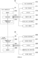
- FIG. 6 is a block diagram showing one example of the configuration of a control system of the diagnosis/treatment support robot system 1 of FIG. 1 .
- the first controller 31 includes a processor 311, a memory 312, and a communication interface 313.
- the processor 311 include a CPU, a MPU, a FPGA (Field Programmable Gate Array), and a PLC (Programmable Logic Controller).
- the memory 312 include a ROM, a RAM, and an external storage device (for example, a SSD (Solid State Drive) and a hard disc drive).
- the communication interface 313 include a modem, an ONU (Optical Network Unit), and a router.
- the first controller 31 performs required control, processing, and the like in such a manner that the processor 311 executes a control program stored in the memory 312.
- the robotic arms 130, the auxiliary instruments 150, the first imager 151, the first speaker 171, the first microphone 172, and the display 173 are connected to the processor 311.
- the second controller 32 includes a processor 321, a memory 322, and a communication interface 323.
- the processor 321 include a CPU, a MPU, a FPGA (Field Programmable Gate Array), and a PLC (Programmable Logic Controller).
- the memory 322 include a ROM, a RAM, and an external storage device (for example, a SSD (Solid State Drive) or a hard disc drive).
- the communication interface 323 include a modem, an ONU (Optical Network Unit), and a router.
- the second controller 32 performs required control, processing, and the like in such a manner that the processor 321 executes a control program stored in the memory 322.
- the communication interface 313 and the communication interface 323 are connected to each other so as to be able to perform data communication.
- Examples of the data communication include wired communication, wireless communication, and optical communication.
- circuitry or processing circuitry which includes general purpose processors, special purpose processors, integrated circuits, ASICs ("Application Specific Integrated Circuits"), conventional circuitry and/or combinations thereof which are configured or programmed to perform the disclosed functionality.
- Processors are considered processing circuitry or circuitry as they include transistors and other circuitry therein.
- the devices, units, or portions are hardware that carry out or are programmed to perform the recited functionality.
- the hardware may be any hardware disclosed herein or otherwise known which is programmed or configured to carry out the recited functionality.
- the hardware is a processor which may be considered a type of circuitry
- the devices, units, or portions are a combination of hardware and software, the software being used to configure the hardware and/or processor.
- FIG. 7 is an external view showing one example of the configuration of an auxiliary robot 90.
- the auxiliary robot 90 includes a cart 92 and a robotic arm 91 disposed on the cart 92.
- the cart 92 can autonomously travel.
- the robotic arm 91 includes an articulated robotic arm.
- the auxiliary robot 90 is manipulated by an operator different from the operator S of the diagnosis/treatment support robot 10 and moves between the normal area and the isolation area while carrying thereon a storage box 93 that houses items (the diagnosis/treatment tools, medicines, and the like) necessary for the auxiliary practice of the diagnosis and the auxiliary practice of the treatment.
- a storage box 93 that houses items (the diagnosis/treatment tools, medicines, and the like) necessary for the auxiliary practice of the diagnosis and the auxiliary practice of the treatment.
- the auxiliary robot 90 assists the auxiliary practice of the diagnosis or the auxiliary practice of the treatment which is performed by the diagnosis/treatment support robot 10.
- the auxiliary robot 90 hands over the diagnosis/treatment tool to the surgical manipulator 6 such that the auxiliary instrument 150 of the surgical manipulator 6 can easily hold the diagnosis/treatment tool.
- the remote controller 20 is disposed in the normal area.
- the diagnosis/treatment support robot 10 is normally disposed in the normal area.
- the operator S manipulates a predetermined operating element (not shown) of the manipulation inputter 210 of the remote controller 20.
- the diagnosis/treatment support robot 10 moves through the preset movement route to the diagnosis/treatment area in the isolation area.
- a disinfector is disposed at a portion of the movement route of the diagnosis/treatment support robot 10, and the diagnosis/treatment support robot 10 is disinfected by the disinfector. Examples of the disinfector include an alcohol spray and an ozone sterilizer.
- a spray container containing a disinfectant solution may be disposed at a portion of the movement route, and the diagnosis/treatment support robot 10 may be manipulated by the operator S to hold the spray container and spray the disinfectant solution to itself for disinfection.
- FIG. 8 is an external view showing the diagnosis/treatment support robot 10 to which the surgical instruments 181 are attached.
- the first speaker 171, the first microphone 172, the display 173, and the like of FIG. 1 are not shown.
- the operator S detaches the surgical instruments 180 from the diagnosis/treatment support robot 10. Then, as shown in FIG. 1 , the operator S attaches the auxiliary instruments 150 and the first imager 151 to the diagnosis/treatment support robot 10.
- the auxiliary robot 90 of FIG. 7 is located beside the diagnosis/treatment support robot 10 and suitably assists the work of the diagnosis/treatment support robot 10 by another operator. The same is true in the other auxiliary practice of the diagnosis and the other auxiliary practice of the treatment.
- the operator S manipulates the manipulation inputter 210 of the remote controller 20 to cause the auxiliary instrument 150 (herein, the holding instrument) of the first robotic arm 130A of the surgical manipulator 6 to hold a swab, insert the swab into the back of the throat of the target person P, collect a swab fluid, and then put the swab into a predetermined container.
- the auxiliary robot 90 puts the predetermined container into the housing box 93.
- the operator S manipulates the first imager 151 by using the third robotic arm 130C so as to be able to easily watch the face of the target person P on the display 220.
- the operator S provides necessary explanations, instructions, and the like to the target person P through the second microphone 232.
- the target person P follows the instructions of the operator S while watching the face of the operator S on the display 173 and listening to the voice of the operator S through the second microphone 232.
- the specimen is collected.
- the operator S manipulates the manipulation inputter 210 of the remote controller 20 so that the auxiliary instrument 150 (holding instrument) of the first robotic arm 130A of the surgical manipulator 6 holds the first hold facilitating jig 81 of the syringe 80 and the auxiliary instrument 150 (holding instrument) of the second robotic arm 130B of the surgical manipulator 6 holds the second hold facilitating jig 82 of the syringe 80.
- the piston 72 is inserted all the way into the cylinder 71 of the syringe 80.
- the operator S manipulates it to insert the injection needle 73 of the syringe 80 into a predetermined part of an arm of the target person P.
- the operator S manipulates the first imager 151 by using the third robotic arm 130C so as to be able to easily watch the arm of the target person P on the display 220.
- the operator S provides necessary explanations, instructions, and the like to the target person P through the second microphone 232.
- the target person P follows the instructions of the operator S while watching the face of the operator S on the display 173 and listening to the voice of the operator S through the second microphone 232.
- the operator S manipulates it to slowly pull back the piston 72 with the cylinder 71 stationary.
- the operator S manipulates it to, when the amount of blood in the cylinder 71 of the syringe 80 on the display 220 reaches a predetermined amount, to pull out the syringe 80 from the arm of the target person P.
- suitable processing is performed together with the auxiliary robot 90.
- the blood is collected.
- the operator S manipulates the manipulation inputter 210 of the remote controller 20 to cause the auxiliary instrument 150 (holding instrument) of the first robotic arm 130A to hold a container containing a drip infusion liquid and suspend the container from a predetermined suspending place. Then, the operator S manipulates it to cause the auxiliary instrument 150 (holding instrument) of the second robotic arm 130B to insert a needle at a tip of a tube for the drip infusion into a predetermined part (for example, the arm) of the target person P. In this process, the operator S manipulates the first imager 151 by using the third robotic arm 130C so as to be able to easily watch the predetermined part of the target person P on the display 220.
- the operator S provides necessary explanations, instructions, and the like to the target person P through the second microphone 232.
- the target person P follows the instructions of the operator S while watching the face of the operator S on the display 173 and listening to the voice of the operator S through the second microphone 232. Thus, the drip infusion work is performed.
- the operator S manipulates the manipulation inputter 210 of the remote controller 20 to cause the auxiliary instrument 150 (holding instrument) of the first robotic arm 130A of the surgical manipulator 6 and the auxiliary instrument 150 (holding instrument) of the second robotic arm 130B of the surgical manipulator 6 to hold the cannula of the artificial heart and lung apparatus at a suitable distance from each other. Then, the operator S manipulates it to cause both of the robotic arms 130A and 130B to slowly insert the cannula into a blood vessel (the main artery or the main vein) at a predetermined part (for example, the root of the lower limb) of the target person P. In this process, the operator S manipulates the first imager 151 by using the third robotic arm 130C so as to be able to easily watch the predetermined part of the target person P on the display 220. Thus, the cannula is inserted.
- the diagnosis/treatment support robot system 1 performs at least either one of the auxiliary practice of the diagnosis or the auxiliary practice of the treatment in place of the medical worker, and with this, the medical worker can be prevented from being infected with the infectious disease.
- the present application example is one example in which the diagnosis/treatment support robot system 1 of the above embodiment is applied to the collection of the specimen of a PCR test for the infectious disease (for example, novel coronavirus (COVID-19)).
- infectious disease for example, novel coronavirus (COVID-19)
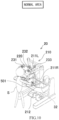
- FIG. 9 is an external view showing one example of the configuration of the diagnosis/treatment support robot 10 of the diagnosis/treatment support robot system 1 according to the application example of the present disclosure which is applied to the PCR test.
- the diagnosis/treatment support robot 10 of the diagnosis/treatment support robot system 1 is disposed in the isolation area, and the remote controller 20 of the diagnosis/treatment support robot system 1 is disposed in the normal area. With this, the operator can be prevented from being infected with the infectious disease.
- the auxiliary imager 151B is attached to the fourth robotic arm 130D of the diagnosis/treatment support robot 10.
- the first imager attached to the third robotic arm 130C is represented by a reference sign 151A and is distinguished from the auxiliary imager 151B.
- Each of the first imager 151A and the auxiliary imager 151B may be a video camera that can take a moving image or an X-ray camera.
- the auxiliary imager 151B may be held by the auxiliary robot as shown in FIG. 7 or may be disposed on a wall of the isolation area.
- auxiliary instrument 150 attached to the first robotic arm 130A and the auxiliary instrument 150 attached to the second robotic arm 130B is a holding instrument 150 shown in FIG. 11 .
- the auxiliary instrument 150 attached to the first robotic arm 130A is the holding instrument 150 shown in FIG. 11 .
- the third robotic arm is referred to as a "first imaging arm”
- the fourth robotic arm 130D is referred to as an "auxiliary imaging arm”
- the robotic arm to which the holding instrument 150 of FIG. 11 is attached is referred to as a "diagnosis/treatment arm.”
- a release operating element 501 is disposed at an appropriate place of the manipulation inputter 210 of the remote controller 20.
- the release operating element 501 when the operator S manipulates the release operating element 501 of the manipulation inputter 210, the release operating element 501 outputs a release signal, and the release signal is input to the first controller 31 through the second controller 32.
- the first controller 31 controls the motor M to open the pair of claws (hereinafter referred to as a "holder") 150c of the holding instrument (auxiliary instrument)150 and controls the operation of the diagnosis/treatment arm 130A such that the holding instrument 150 moves away from the target person P as described below.
- FIG. 11 is an external view showing one example of the configuration of the holding instrument 150 of FIG. 9 .
- a pair of laser beam indicators (laser pointers) 701A and 701B are disposed at the claw holding body 150b.
- the number of laser beam indicators may be three or more.
- the size of an irradiation spot of the laser beam is suitably selected.
- the pair of laser beam indicators 701A and 701B are located at both sides of the claw holding body 150b in a predetermined open-close direction of the pair of claws 150c of the claw holding body 150b.
- the pair of laser beam indicators 701A and 701B are arranged such that the laser beam emitted from the laser beam indicator 701A and the laser beam emitted from the laser beam indicator 701B intersect with each other and are located on the same plane as a central axis 700 of the holder (the pair of claws) 150c.
- the central axis 700 of the holder (the pair of claws) 150c is defined as, for example, a virtual axis which coincides with a central axis of the columnar coupler 150e and extends on a virtual plane with which the pair of claws 150c are closed to come into contact.
- a first end of a swab 601 is held by the holder 150c such that the swab 601 extends along the central axis 700.
- the swab 601 may extend in the vicinity of the central axis 700.
- the pair of laser beam indicators 701A and 701B are arranged such that a laser beam 702A emitted from the laser beam indicator 701A and a laser beam 702B emitted from the laser beam indicator 701B intersect with each other in a region beyond a tip (second end) of the swab 601 in a direction from the first end held by the holder 150c toward the second end of the swab 601.
- a distance between an irradiation part of the target person P and the swab 601 i.e., a distance between a specimen collection part of the target person P and the swab 601 can be determined based on an interval between the irradiation spots (see FIG. 13 ; the irradiation spots are not shown) on the target person P by the pair of laser beams 702A and 702B.
- the pair of laser beam indicators 701A and 701B include, for example, power supplies (for example, batteries), and on and off of the power supplies are controlled through the second controller 32 and the first controller 31 by the operator S who manipulates a corresponding operating element (not shown) of the manipulation inputter 210.
- power supplies for example, batteries
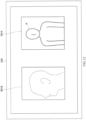
- FIG. 12 is a schematic diagram showing an image 901A taken by the first imager 151A and an image 901B taken by the auxiliary imager 151B which are displayed on the display 220 of the remote controller 20.
- the operation of the auxiliary imager 151B is controlled through the second controller 32 and the first controller 31 by the operator S who manipulates a corresponding operating element (not shown) of the manipulation inputter 210.
- the image 901B taken by the auxiliary imager 151B is transmitted to the second controller 32 through the first controller 31 and is displayed on the display 220 by the second controller 32.
- the image taken by the auxiliary imager 151B is displayed alone or in combination with another image.
- the target person P sits on a chair, and a sterilized swab (hereinafter simply referred to as a "swab") is inserted into a nose or a mouth of the target person P.
- a sterilized swab hereinafter simply referred to as a "swab"
- the specimen of the infectious disease is collected by the swab.
- a nasopharynx swab fluid is collected.
- a throat swab fluid saliva in the oral cavity is collected.
- an imaging target may be the nasal cavity of the target person P.
- the imaging target may be the oral cavity of the target person P.
- the suction catheter is held and handled by the auxiliary instrument 150 (holding instrument) of the second robotic arm 130B.
- the operator S performs manipulation so as to move the first imaging arm 130C to take an image of a front side of the face of the target person P by the first imager 151A and move the auxiliary imaging arm 130D to take an image of a lateral side of the face of the target person P by the auxiliary imager 151B.
- the image 901A taken by the first imager 151A and the image 902 taken by the auxiliary imager 151B are displayed on the display 220 of the remote controller 20.
- the image of the face of the operator S is taken by the second imager 233, and the taken image is displayed on the display 173 of the surgical manipulator 6.
- the operator S makes simple medical inquiries to the target person P while watching the display 220. For example, the operator S asks "How are you feeling?" Then, this inquiry is acquired by the second microphone 232, and the first speaker 171 outputs the sounds of this inquiry. The target person P answers "I have a slight fever” while watching the display 173. Then, this answer is acquired by the first microphone 172, and the second speaker 231 outputs the sounds of this answer. The operator S listens to this answer and says “I see. Let's have a medical examination," and the target person P says "Yes, please.”
- FIG. 13 is a schematic diagram showing the image 901A taken by the first imager 151A and the image 901B taken by the auxiliary imager 151B which are displayed on the display 220 of the remote controller 20 at the time of the collection of the specimen.
- the operator S performs manipulation so as to move the first imaging arm 130C to take the zoom-up image 901A of the nose of the target person by the first imager 151A from the front side of the target person. Then, the operator S performs manipulation so as to move the auxiliary imaging arm 130D to take the image 901B of an oblique lateral side of the face of the target person P by the auxiliary imager 151B.
- the operator S manipulates the diagnosis/treatment arm 130A to insert the swab 601 into the back of the nose, wipe the back of the nose with the tip of the swab 601, and thus, collect the specimen.
- the operator S watches the reaction of the target person P regarding the collection of the specimen by the image 901B showing the oblique lateral side of the face (i.e., whether the target person P frowns, moves his/her face backward, or is calm).
- the operator S manipulates the diagnosis/treatment arm 130Ato pull out the swab, which has collected the specimen, from the nose of the target person P and store the swab in a predetermined container.
- the operator S manipulates the release operating element 501 of the manipulation inputter 210.
- the holder 150c of the holding instrument 150 opens to release the swab 601, and the diagnosis/treatment arm 130A operates such that the holding instrument 150 moves away from the target person P.
- the operator S can collect the specimen while confirming the distance between the swab 601 and the specimen collection part by the zoom-up image 901A of the nose and knowing the reaction of the target person regarding the collection of the specimen by the image 901B showing the oblique lateral side of the face. Therefore, the operator S can collect the specimen without hurting the target person. Moreover, the target person P can be protected from the emergency.
- the doctor can perform communication (make medical inquiries) regarding the diagnosis by the sounds.
- FIG. 14 is a schematic diagram showing the image 901A taken by the first imager 151A, the image 901B taken by the auxiliary imager 151B, and a first swab insertion degree model 901C, which are displayed on the display 220 of the remote controller 20.
- the display 220 displays a swab insertion degree model that shows the degree of insertion of the swab 601 into the body of the target person P.
- the first swab insertion degree model 901C is displayed as the swab insertion degree model.
- the swab 601 is shown in the nasal cavity of a face lateral side model 902 that imitates the lateral side of the face of the target person P. Then, the position of the swab 601 is changed in accordance with the degree of actual insertion of the swab 601 into the nose by the holding instrument 150.
- the second controller 32 determines the position of the swab 601 in the first swab insertion degree model 901C, based on the position of the swab 601 and an assumed position of the face of the target person P in a coordinate system of the diagnosis/treatment support robot 10.
- the position of the swab 601 and the assumed position of the face of the target person P may be input from the first controller 31.
- a position sensor may be mounted on the holding instrument 150, and the position of the swab 601 in the first swab insertion degree model 901C may be determined based on the output of the position sensor.
- Modified Example 1 it is preferable to prepare a chair which is adjustable such that the face of the target person P is located at the above assumed position.
- the image 901A or the image 901B may be omitted.
- the operator S can smoothly insert the swab 601 into the specimen collection part of the nose of the target person P while watching the first swab insertion degree model 901C. Therefore, the specimen can be quickly and accurately collected.
- FIG. 15 is a schematic diagram showing the image 901A taken by the first imager 151A, the image 901B taken by the auxiliary imager 151B, and a second swab insertion degree model 901D, which are displayed on the display 220 of the remote controller 20.
- the second swab insertion degree model 901D is displayed as the swab insertion degree model.
- the second swab insertion degree model 901D a portion 601a that is not in the nose and a portion 601b that is in the nose are shown on the model of the swab 601. Then, a boundary between these portions is changed in accordance with the degree of actual insertion of the swab 601 into the nose by the holding instrument 150. In this case, for example, the portion 601b in the nose may be displayed in color.
- the position of the boundary between these portions is determined in the same manner as Modified Example 1.
- the image 901A or the image 901B may be omitted.
- the operator S can smoothly insert the swab 601 into the specimen collection part of the nose of the target person P while watching the second swab insertion degree model 901D. Therefore, the specimen can be quickly and accurately collected.
- a swab insertion degree model that shows the degree of insertion of the swab 601 into the oral cavity of the target person P may be displayed on the display 220.
- Each of the diagnosis/treatment support robot system 1 according to the above embodiment and the diagnosis/treatment support robot system 1 according to the application example to the PCR test may be located in a medical movable body (for example, a hospital ship or a railcar).
- a medical movable body for example, a hospital ship or a railcar.
- the second controller 32 may have a learning function. Specifically, the second controller 32 may include a manipulation storage that stores all manipulation inputs to the manipulation inputter 210 by the operator S or a manipulation learning unit that uses machine learning to learn the manipulation inputs to the manipulation inputter 210 by the operator S.
- the second controller 32 includes the manipulation storage
- the stored manipulation inputs that are output from the manipulation storage are used for the operation control of the diagnosis/treatment support robot 10 instead of the manipulation inputs from the manipulation inputter 210.
- the manipulation inputs from the manipulation inputter 210 and suitable operation data, such as the display image of the display 220, are input as learning data to the manipulation learning unit.
- the learned manipulation inputs that are output from the manipulation learning unit are used for the operation control of the diagnosis/treatment support robot 10 instead of the manipulation inputs from the manipulation inputter 210.
- diagnosis/treatment support robot 10 can autonomously perform the auxiliary practice of the diagnosis or the auxiliary practice of the treatment.
- the surgical manipulator 6 may include a plurality of the robotic arms 130.
- the operator S can move at least two robotic arms 130 as with human arms. Therefore, even when the auxiliary practice of the diagnosis or the auxiliary practice of the treatment is complex, the operator S can appropriately perform the auxiliary practice of the diagnosis or the auxiliary practice of the treatment.
- the auxiliary instrument 150 may have four or more degrees of freedom of movement of the auxiliary instrument 150, and the instrument mount 137 may allow the auxiliary instrument 150 to operate in four or more degrees of freedom of movement thereof.
- the auxiliary practice of the diagnosis or the auxiliary practice of the treatment which is complex can be appropriately performed by operating the auxiliary instrument 150 having four or more degrees of freedom of movement thereof.
- the surgical manipulator 6 may be at the cart 70 that can autonomously travel.
- the diagnosis/treatment support robot 10 (surgical manipulator 6) can move between the normal area and the isolation area.
- the isolation area that isolates an infected person or a suspected infected person may include an area where at least either one of the auxiliary practice of the diagnosis of the infectious disease or the auxiliary practice of the treatment of the infectious disease is performed for the target person P.
- the surgical manipulator 6 and the cart 70 may move to the isolation area from the normal area that is not the isolation area.
- the surgical manipulator 6 and the cart 70 may be disinfected before entering into the isolation area from the normal area or after getting out from the isolation area toward the normal area.
- the surgical manipulator 6 and the cart 70 can enter into the isolation area after the disinfection, or the surgical manipulator 6 and the cart 70 which have gotten out from the isolation area can move to the normal area after the disinfection. Therefore, the infection of a person due to the surgical manipulator 6 and the cart 70 can be prevented.
- the auxiliary instrument 150 may be a holding instrument that holds the diagnosis/treatment tool.
- the medical worker holds the diagnosis/treatment tool with his/her hands in many cases. Therefore, the holding instrument can hold the diagnosis/treatment tool so as to widely perform the auxiliary practice of the diagnosis or the auxiliary practice of the treatment in place of the medical worker.
- the holding instrument can hold the diagnosis/treatment tool so as to widely perform the auxiliary practice of the diagnosis or the auxiliary practice of the treatment in place of the medical worker.
- the diagnosis/treatment tool may be a tool that collects a specimen regarding an infectious disease of the target person P; a drip infusion tool; a blood collecting tool; or a cannula of an artificial heart and lung apparatus.
- the robotic arm 30 may be manipulated by the operator S in a master-slave mode.
- the robotic arm 130 can be suitably manipulated.
- the hold facilitating jig 81, 82 by which the holding instrument easily holds the diagnosis/treatment tool may be attached to the diagnosis/treatment tool.
- diagnosis/treatment tools are difficult for the holding instrument to directly hold.
- examples of such tools include: fragile tools (syringes, containers, and the like made of glass); too thin or too small tools (thin tubes and the like); and tools that are difficult to be held since the shapes thereof are complex.
- a jig that is easy for the holding instrument to hold may be attached to such diagnosis/treatment tool in advance. With this, the holding instrument holds the jig, and as a result, the holding instrument can easily hold the diagnosis/treatment tool.
- the diagnosis/treatment support robot system 1 may further include the hold facilitating jigs 81 and 82.
- the diagnosis/treatment tool that is difficult to directly be held can be easily held by the auxiliary instrument 150.
- the diagnosis/treatment support robot 10 may include: the first speaker 171 that transmits to the target person P, the voice of the operator S which is acquired by the second microphone 232; and the first microphone 172 that acquires the voice of the target person P.
- the remote controller 20 may include: the second speaker 31 that transmits to the operator S, the voice of the target person P which is acquired by the first microphone 172; and the second microphone 232 that acquires the voice of the operator S.
- the operator S can appropriately perform the auxiliary practice of the diagnosis or the auxiliary practice of the treatment while communicating with the target person P through dialogue.
- the diagnosis/treatment support robot 10 may be in the isolation area that isolates an infected person or a suspected infected person, and the remote controller 20 may be in the normal area that is not the isolation area.
- the surgical manipulator 6 of the diagnosis/treatment support robot 10 located in the isolation area can be manipulated by the remote controller 20 located in the normal area. Therefore, the operator S can be prevented from being infected with the infectious disease.
- the holding instrument 150 may include the laser beam indicators 701A and 701B, and the laser beam indicators 701A and 701B may be located such that the laser beam 702A emitted from the laser beam indicator 701A and the laser beam 702B emitted from the laser beam indicator 701B intersect with each other.
- the auxiliary practice of the diagnosis or the auxiliary practice of the treatment is performed for the target person P by using the diagnosis/treatment tool held by the holding instrument 150
- the distance between the irradiation part of the target person P and the diagnosis/treatment tool i.e., the distance between the target part for the auxiliary practice and the diagnosis/treatment tool can be determined based on the interval between the irradiation spots on the target person P by the laser beams 702A and 702B.
- the auxiliary practice of the diagnosis or the auxiliary practice of the treatment can be appropriately performed.
- the diagnosis/treatment tool having a rod shape may be the swab 601 that collects the specimen of the infectious disease from the target person P.
- the holding instrument 150 may include the holder 150c that can hold the first end of the swab 601.
- the holder 150c and the laser beam indicators 701A and 701B may be located such that a region where the laser beams 702A and 702B emitted from the laser beam indicators 701A and 701B intersect with each other is located closer to the second end of the swab 601 than to the holder 150c in a direction from the first end held by the holder 150c toward the second end of the swab 601.
- the distance between the irradiation part of the target person P and the swab 601, i.e., the distance between the specimen collection part and the swab 601 can be suitably obtained based on the interval between the irradiation spots on the target person P by the laser beams 702A and 702B.
- the diagnosis/treatment support robot system 1 may include the auxiliary imager 151B that takes the image of the lateral side of the face of the target person P.
- the first imager 151A may take the image of the front side of the face of the target person P.
- the second display 220 may display the image taken by the first imager 151A and/or the image taken by the auxiliary imager 151B.
- the auxiliary imager 151B may be attached to the robotic arm 130, another robot, a wall of the isolation area, or the like.
- the first imager 151A exclusively takes the zoom-up image of the nose or the mouth of the target person P from the front side. Therefore, the operator S cannot know the reaction of the target person P regarding the collection of the specimen (whether the target person P frowns, moves his/her face backward, or is calm).
- the auxiliary imager 151B takes the image of the lateral side of the face of the target person P, the operator can know the reaction of the target person P regarding the collection of the specimen based on the lateral side of the face in the taken image. Therefore, the operator S can collect the specimen without hurting the target person P.
- the robotic arms 130 may further include the auxiliary imaging arm 130D including the instrument mount 137 to which the auxiliary imager 151B is attached.
- the image of the lateral side of the face of the target person P can be appropriately taken from a desired angle and a desired distance.
- the second display 220 may display the swab insertion degree model 901C, 901D at least together with the image taken by the first imager 151A or the image taken by the auxiliary imager 151B, and the swab insertion degree model 901C, 901D may indicate the degree of insertion of the swab 601 into the body of the target person P.
- the degree of insertion of the swab may be determined based on the position of the swab 601 and the assumed position of the face of the target person P in the robot coordinate system.
- the operator S can smoothly insert the swab 601 into the specimen collection part in the body of the target person P while watching the swab insertion degree model 901C, 901D.
- the specimen can be quickly and accurately collected.
- the remote controller 20 may include the release operating element 501.
- the surgical manipulator 6 may release the swab 601 held by the holding instrument attached to the instrument mount 137 of the diagnosis/treatment arm.
- the swab 601 held by the holding instrument is released. Therefore, the target person P can be protected from the emergency.
- the surgical manipulator 6 may operate the diagnosis/treatment arm to move the holding instrument away from the target person P.
- the target person P can be more suitably protected from the emergency.
- the diagnosis/treatment support robot, the diagnosis/treatment support robot system, and the diagnosis/treatment support method according to the present disclosure are useful as a diagnosis/treatment support robot, a diagnosis/treatment support robot system, and a diagnosis/treatment support method, each of which performs at least either one of a diagnosis or a treatment in place of a medical worker and therefore can prevent the medical worker from being infected with an infectious disease.
Landscapes
- Health & Medical Sciences (AREA)
- Life Sciences & Earth Sciences (AREA)
- Surgery (AREA)
- Engineering & Computer Science (AREA)
- General Health & Medical Sciences (AREA)
- Public Health (AREA)
- Veterinary Medicine (AREA)
- Biomedical Technology (AREA)
- Heart & Thoracic Surgery (AREA)
- Medical Informatics (AREA)
- Molecular Biology (AREA)
- Animal Behavior & Ethology (AREA)
- Nuclear Medicine, Radiotherapy & Molecular Imaging (AREA)
- Robotics (AREA)
- Pathology (AREA)
- Oral & Maxillofacial Surgery (AREA)
- Gynecology & Obstetrics (AREA)
- Radiology & Medical Imaging (AREA)
- Hematology (AREA)
- Physics & Mathematics (AREA)
- Biophysics (AREA)
- Manipulator (AREA)
- Cleaning Or Drying Semiconductors (AREA)
- Container, Conveyance, Adherence, Positioning, Of Wafer (AREA)
Applications Claiming Priority (3)
| Application Number | Priority Date | Filing Date | Title |
|---|---|---|---|
| JP2020071351 | 2020-04-10 | ||
| JP2020094574 | 2020-05-29 | ||
| PCT/JP2021/015000 WO2021206161A1 (ja) | 2020-04-10 | 2021-04-09 | 診断/治療支援ロボット、診断/治療支援ロボットシステム、及び診断/治療支援方法 |
Publications (2)
| Publication Number | Publication Date |
|---|---|
| EP4134037A1 true EP4134037A1 (de) | 2023-02-15 |
| EP4134037A4 EP4134037A4 (de) | 2024-05-01 |
Family
ID=78023566
Family Applications (1)
| Application Number | Title | Priority Date | Filing Date |
|---|---|---|---|
| EP21784597.3A Pending EP4134037A4 (de) | 2020-04-10 | 2021-04-09 | Diagnose-/behandlungshilfsroboter, diagnose-/behandlungshilfsrobotersystem und diagnose-/behandlungshilfsverfahren |
Country Status (6)
| Country | Link |
|---|---|
| US (1) | US12310689B2 (de) |
| EP (1) | EP4134037A4 (de) |
| JP (2) | JP7633234B2 (de) |
| CN (1) | CN115361921A (de) |
| TW (1) | TWI821650B (de) |
| WO (1) | WO2021206161A1 (de) |
Families Citing this family (6)
| Publication number | Priority date | Publication date | Assignee | Title |
|---|---|---|---|---|
| JP7492081B2 (ja) * | 2021-04-26 | 2024-05-28 | 川崎重工業株式会社 | ロボットシステム |
| KR102621421B1 (ko) * | 2021-11-25 | 2024-01-10 | 주식회사 원드롭 | 검체 채취의 신뢰도 평가 장치 및 방법 |
| KR102715765B1 (ko) * | 2022-03-15 | 2024-10-11 | 한국기계연구원 | 검진도구 삽입 시스템 및 이를 이용한 검진도구 삽입방법 |
| KR102715764B1 (ko) * | 2022-03-15 | 2024-10-11 | 한국기계연구원 | 스왑부의 삽입 판단시스템, 이를 포함하는 스왑 가이드 시스템 및 스왑 가이드 시스템을 이용한 스왑 가이드 방법 |
| CN117462777A (zh) * | 2023-12-14 | 2024-01-30 | 深圳市儿童医院 | 一种吸痰车 |
| CN117838303B (zh) * | 2024-01-31 | 2024-08-02 | 中山大学附属第五医院 | 一种疼痛治疗仪器的辅助装置和系统 |
Family Cites Families (33)
| Publication number | Priority date | Publication date | Assignee | Title |
|---|---|---|---|---|
| JP3183876B2 (ja) * | 1988-05-16 | 2001-07-09 | 株式会社東芝 | 手術支援装置 |
| JPH08280697A (ja) * | 1995-04-20 | 1996-10-29 | Olympus Optical Co Ltd | 手術用マニピュレータシステム |
| US8182469B2 (en) * | 1997-11-21 | 2012-05-22 | Intuitive Surgical Operations, Inc. | Surgical accessory clamp and method |
| DE19882221T1 (de) * | 1997-03-17 | 2000-02-10 | Canadian Space Agency Saint Hu | Verfahren und Vorrichtung zum automatischen Impfen von Kulturmedien mit bakteriellen Proben aus klinischen Probenbehältern |
| US6309397B1 (en) * | 1999-12-02 | 2001-10-30 | Sri International | Accessories for minimally invasive robotic surgery and methods |
| JP4477174B2 (ja) * | 1999-11-19 | 2010-06-09 | オリンパス株式会社 | 被検体観察装置 |
| JP2002085353A (ja) * | 2000-09-11 | 2002-03-26 | Mamoru Mitsuishi | 遠隔診断システム |
| JP4110457B2 (ja) * | 2002-06-05 | 2008-07-02 | 株式会社日立メディコ | 医療画像診断装置 |
| JP2005261734A (ja) | 2004-03-19 | 2005-09-29 | Olympus Corp | 内視鏡用処置具及び内視鏡処置システム |
| JP4212057B2 (ja) | 2005-11-11 | 2009-01-21 | 株式会社アステックコーポレーション | 採血システム |
| US10368838B2 (en) * | 2008-03-31 | 2019-08-06 | Intuitive Surgical Operations, Inc. | Surgical tools for laser marking and laser cutting |
| US8864652B2 (en) * | 2008-06-27 | 2014-10-21 | Intuitive Surgical Operations, Inc. | Medical robotic system providing computer generated auxiliary views of a camera instrument for controlling the positioning and orienting of its tip |
| CN100579479C (zh) * | 2008-07-03 | 2010-01-13 | 哈尔滨工程大学 | 内镜操作手术机器人穿刺孔定位装置 |
| US9842192B2 (en) * | 2008-07-11 | 2017-12-12 | Intouch Technologies, Inc. | Tele-presence robot system with multi-cast features |
| US20110071541A1 (en) * | 2009-09-23 | 2011-03-24 | Intuitive Surgical, Inc. | Curved cannula |
| IT1401669B1 (it) * | 2010-04-07 | 2013-08-02 | Sofar Spa | Sistema di chirurgia robotizzata con controllo perfezionato. |
| CN102478400A (zh) * | 2010-11-22 | 2012-05-30 | 山东超瑞施生物磁学工程技术研究中心 | 一种医用诊断仪光纤探头的精密定位装置 |
| US8574240B2 (en) * | 2011-01-07 | 2013-11-05 | Preceptis Medical, Inc. | Stabilization system and aspiration device with protected cutting edge |
| US9642606B2 (en) * | 2012-06-27 | 2017-05-09 | Camplex, Inc. | Surgical visualization system |
| US11529205B2 (en) * | 2015-06-23 | 2022-12-20 | The Regents Of The University Of California | Precision injector/extractor for robot-assisted minimally-invasive surgery |
| WO2017002143A1 (ja) | 2015-06-29 | 2017-01-05 | 川崎重工業株式会社 | 手術ロボット |
| JP6654883B2 (ja) | 2015-12-11 | 2020-02-26 | 川崎重工業株式会社 | 外科手術システム、マニピュレータアーム、及びマニピュレータアーム支持体 |
| JP6654884B2 (ja) | 2015-12-11 | 2020-02-26 | 川崎重工業株式会社 | 外科手術システム |
| CN105877846B (zh) * | 2016-03-30 | 2018-05-08 | 佳木斯大学 | 口腔诊疗机器人系统及其控制方法 |
| CN107693118B (zh) * | 2016-08-08 | 2020-10-16 | 上海联影医疗科技有限公司 | X射线成像设备及其目标区域指示方法 |
| DE102017201437A1 (de) * | 2017-01-30 | 2018-08-02 | Fresenius Medical Care Deutschland Gmbh | System und Verfahren zur automatisierten Kanülierung |
| US11564757B2 (en) * | 2017-02-27 | 2023-01-31 | The Regents Of The University Of California | Laser-assisted surgical alignment |
| US10813710B2 (en) * | 2017-03-02 | 2020-10-27 | KindHeart, Inc. | Telerobotic surgery system using minimally invasive surgical tool with variable force scaling and feedback and relayed communications between remote surgeon and surgery station |
| US11642184B2 (en) | 2017-06-27 | 2023-05-09 | The Johns Hopkins University | Universal surgical tool exchange and identification system |
| FR3073135B1 (fr) | 2017-11-09 | 2019-11-15 | Quantum Surgical | Dispositif robotise pour une intervention medicale mini-invasive sur des tissus mous |
| US20190331701A1 (en) | 2018-04-30 | 2019-10-31 | Lonza Limited | System and Method for Environmental Monitoring |
| CN209826974U (zh) | 2019-02-28 | 2019-12-24 | 南京天奥医疗仪器制造有限公司 | 内窥镜机械臂移动车用移动单元 |
| CN110948505B (zh) | 2020-02-21 | 2020-06-02 | 上海木承智能医疗科技有限公司 | 医用自消毒物流机器人及其控制方法 |
-
2021
- 2021-04-09 CN CN202180024802.4A patent/CN115361921A/zh active Pending
- 2021-04-09 TW TW110112921A patent/TWI821650B/zh active
- 2021-04-09 US US17/995,739 patent/US12310689B2/en active Active
- 2021-04-09 WO PCT/JP2021/015000 patent/WO2021206161A1/ja not_active Ceased
- 2021-04-09 EP EP21784597.3A patent/EP4134037A4/de active Pending
- 2021-04-09 JP JP2022514129A patent/JP7633234B2/ja active Active
-
2024
- 2024-12-03 JP JP2024210577A patent/JP2025027125A/ja active Pending
Also Published As
| Publication number | Publication date |
|---|---|
| JP7633234B2 (ja) | 2025-02-19 |
| TW202203864A (zh) | 2022-02-01 |
| JPWO2021206161A1 (de) | 2021-10-14 |
| TWI821650B (zh) | 2023-11-11 |
| US12310689B2 (en) | 2025-05-27 |
| WO2021206161A1 (ja) | 2021-10-14 |
| US20230165650A1 (en) | 2023-06-01 |
| EP4134037A4 (de) | 2024-05-01 |
| CN115361921A (zh) | 2022-11-18 |
| JP2025027125A (ja) | 2025-02-26 |
Similar Documents
| Publication | Publication Date | Title |
|---|---|---|
| US12310689B2 (en) | Diagnosis/treatment support robot, diagnosis/treatment support robot system, and diagnosis/treatment support method | |
| Zhong et al. | Foot-controlled robot-enabled endoscope manipulator (freedom) for sinus surgery: Design, control, and evaluation | |
| TWI804847B (zh) | 機器人系統及機器人系統的控制方法 | |
| JP6920575B1 (ja) | ロボットシステムおよびロボットシステムの制御方法 | |
| JP2024081691A (ja) | 医療用移動体システム及びその運転方法 | |
| US12588962B2 (en) | Medical support robot and medical robot system | |
| Verma et al. | IoT and robotics in healthcare | |
| Wang et al. | A 5-DOFs robot for posterior segment eye microsurgery | |
| Liu et al. | A remotely controlled oropharyngeal swab sampling robot and its application in covid-19 prevention | |
| Sarayu et al. | Revolutionizing Healthcare: Exploring Robotics' Role and Impact in the Recent Years | |
| US20250331939A1 (en) | Systems and methods for sterilization and storage of a sterilized teleoperated component | |
| KR20250049077A (ko) | 로보틱 프로시저 시스템 및 로보틱 프로시저 방법 | |
| JP2022169201A (ja) | ロボットシステム | |
| Verma et al. | 10 IoT and Robotics | |
| Wang¹⁴ et al. | A 5-DOFs Robot for Posterior Segment Eye Microsurgery |
Legal Events
| Date | Code | Title | Description |
|---|---|---|---|
| STAA | Information on the status of an ep patent application or granted ep patent |
Free format text: STATUS: THE INTERNATIONAL PUBLICATION HAS BEEN MADE |
|
| PUAI | Public reference made under article 153(3) epc to a published international application that has entered the european phase |
Free format text: ORIGINAL CODE: 0009012 |
|
| STAA | Information on the status of an ep patent application or granted ep patent |
Free format text: STATUS: REQUEST FOR EXAMINATION WAS MADE |
|
| 17P | Request for examination filed |
Effective date: 20221027 |
|
| AK | Designated contracting states |
Kind code of ref document: A1 Designated state(s): AL AT BE BG CH CY CZ DE DK EE ES FI FR GB GR HR HU IE IS IT LI LT LU LV MC MK MT NL NO PL PT RO RS SE SI SK SM TR |
|
| DAV | Request for validation of the european patent (deleted) | ||
| DAX | Request for extension of the european patent (deleted) | ||
| A4 | Supplementary search report drawn up and despatched |
Effective date: 20240405 |
|
| RIC1 | Information provided on ipc code assigned before grant |
Ipc: A61B 90/00 20160101ALN20240328BHEP Ipc: A61B 10/00 20060101ALN20240328BHEP Ipc: G01N 1/02 20060101ALI20240328BHEP Ipc: A61B 34/37 20160101AFI20240328BHEP |
|
| GRAP | Despatch of communication of intention to grant a patent |
Free format text: ORIGINAL CODE: EPIDOSNIGR1 |
|
| STAA | Information on the status of an ep patent application or granted ep patent |
Free format text: STATUS: GRANT OF PATENT IS INTENDED |
|
| RIC1 | Information provided on ipc code assigned before grant |
Ipc: A61B 34/37 20160101AFI20251002BHEP Ipc: G01N 1/02 20060101ALI20251002BHEP Ipc: A61B 10/00 20060101ALN20251002BHEP Ipc: A61B 90/00 20160101ALN20251002BHEP Ipc: A61B 10/02 20060101ALN20251002BHEP Ipc: A61B 5/15 20060101ALN20251002BHEP |
|
| INTG | Intention to grant announced |
Effective date: 20251014 |