EP4134041B1 - Ébauche dentaire et procédé de production d'une prothèse partielle dentaire - Google Patents
Ébauche dentaire et procédé de production d'une prothèse partielle dentaire Download PDFInfo
- Publication number
- EP4134041B1 EP4134041B1 EP21190667.2A EP21190667A EP4134041B1 EP 4134041 B1 EP4134041 B1 EP 4134041B1 EP 21190667 A EP21190667 A EP 21190667A EP 4134041 B1 EP4134041 B1 EP 4134041B1
- Authority
- EP
- European Patent Office
- Prior art keywords
- blank
- tooth
- interface
- elevations
- depressions
- Prior art date
- Legal status (The legal status is an assumption and is not a legal conclusion. Google has not performed a legal analysis and makes no representation as to the accuracy of the status listed.)
- Active
Links
Images



Classifications
-
- A—HUMAN NECESSITIES
- A61—MEDICAL OR VETERINARY SCIENCE; HYGIENE
- A61C—DENTISTRY; APPARATUS OR METHODS FOR ORAL OR DENTAL HYGIENE
- A61C13/00—Dental prostheses; Making same
- A61C13/0003—Making bridge-work, inlays, implants or the like
- A61C13/0022—Blanks or green, unfinished dental restoration parts
-
- A—HUMAN NECESSITIES
- A61—MEDICAL OR VETERINARY SCIENCE; HYGIENE
- A61C—DENTISTRY; APPARATUS OR METHODS FOR ORAL OR DENTAL HYGIENE
- A61C1/00—Dental machines for boring or cutting ; General features of dental machines or apparatus, e.g. hand-piece design
- A61C1/0007—Control devices or systems
-
- A—HUMAN NECESSITIES
- A61—MEDICAL OR VETERINARY SCIENCE; HYGIENE
- A61C—DENTISTRY; APPARATUS OR METHODS FOR ORAL OR DENTAL HYGIENE
- A61C13/00—Dental prostheses; Making same
- A61C13/0003—Making bridge-work, inlays, implants or the like
- A61C13/0004—Computer-assisted sizing or machining of dental prostheses
-
- A—HUMAN NECESSITIES
- A61—MEDICAL OR VETERINARY SCIENCE; HYGIENE
- A61C—DENTISTRY; APPARATUS OR METHODS FOR ORAL OR DENTAL HYGIENE
- A61C13/00—Dental prostheses; Making same
- A61C13/0003—Making bridge-work, inlays, implants or the like
- A61C13/0006—Production methods
-
- A—HUMAN NECESSITIES
- A61—MEDICAL OR VETERINARY SCIENCE; HYGIENE
- A61C—DENTISTRY; APPARATUS OR METHODS FOR ORAL OR DENTAL HYGIENE
- A61C13/00—Dental prostheses; Making same
- A61C13/01—Palates or other bases or supports for the artificial teeth; Making same
-
- A—HUMAN NECESSITIES
- A61—MEDICAL OR VETERINARY SCIENCE; HYGIENE
- A61C—DENTISTRY; APPARATUS OR METHODS FOR ORAL OR DENTAL HYGIENE
- A61C13/00—Dental prostheses; Making same
- A61C13/08—Artificial teeth; Making same
- A61C13/082—Cosmetic aspects, e.g. inlays; Determination of the colour
-
- A—HUMAN NECESSITIES
- A61—MEDICAL OR VETERINARY SCIENCE; HYGIENE
- A61C—DENTISTRY; APPARATUS OR METHODS FOR ORAL OR DENTAL HYGIENE
- A61C13/00—Dental prostheses; Making same
- A61C13/225—Fastening prostheses in the mouth
- A61C13/26—Dentures without palates; Partial dentures, e.g. bridges
-
- G—PHYSICS
- G06—COMPUTING OR CALCULATING; COUNTING
- G06F—ELECTRIC DIGITAL DATA PROCESSING
- G06F30/00—Computer-aided design [CAD]
- G06F30/20—Design optimisation, verification or simulation
-
- A—HUMAN NECESSITIES
- A61—MEDICAL OR VETERINARY SCIENCE; HYGIENE
- A61C—DENTISTRY; APPARATUS OR METHODS FOR ORAL OR DENTAL HYGIENE
- A61C2201/00—Material properties
- A61C2201/002—Material properties using colour effect, e.g. for identification purposes
Definitions
- the invention relates to a dental blank according to the preamble of claim 1 and a method for producing a dental partial prosthesis according to the preamble of claim 8.
- partial dentures consist of several parts and different materials.
- the size of partial dentures depends on the patient's specific dental situation. This can vary greatly from individual to individual compared to full dentures, as each patient has a different number and size of gaps.
- the printed matter US 2018/071063 A1 refers to a dental prosthesis made from a one- or two-piece prosthesis blank composed of a gum-colored material and a tooth-colored material.
- the interface between the materials is wavy along the dental arch and radial in the vestibular direction.
- the extension of the partial denture is preferably perpendicular to the peripheral (partial) circumferential extension of the elevations and depressions, including the apex of the elevations.
- the partial denture can extend essentially radially, but can also be slightly oblique to the radius, e.g., deviating from the radius by +/- 20 degrees.
- the tooth-colored material at the interface between the two materials has the exact negative shape of the flesh-colored material.
- the interface between the materials has annular elevations and depressions so that the two materials interlock and are, as it were, interlocked.
- the flesh-colored material can be polymerized onto the tooth-colored material.
- a layer of adhesive, joining, or composite material is located between the two materials to firmly bond the two materials. It may also be particularly advantageous to bond the two materials using additive processes, pressing, or other bonding techniques.
- the pattern i.e. the The spiral or the circle or the plurality of circles share a common center point with the center point of the disc, in particular the center point of the blank, and thus have a central and common center point.
- eccentric circles i.e., circles with different centers, and/or to provide the centers of these and/or the starting point of the spiral in an inner region of the disc-shaped blank, for example, in the inner quarter, the inner third, or the inner half of the blank.
- the tooth-colored material at the interface between the two materials displays the exact negative form of the flesh-colored material. This supports the strength and resistance of the bond, especially of an adhesive joint, between the two materials against forces acting on it, for example, during further processing of the blank, but also during everyday use of the final partial denture.
- the elevations and depressions become wider and higher from the center outwards.
- the rings therefore run in cross-section from the inner region of the blank or from the center to the edge with a changing amplitude and/or frequency. Partial dentures that are machined, in particular milled, in the outer region of the blank therefore automatically have larger dimensions than partial dentures that are machined, in particular milled, close to the center of the blank.
- molars and premolars are required more frequently than canines and incisors, and according to the invention, the outer region of the disc-shaped blank offers more space for the arrangement of the molars and premolars, which in this respect harmonizes with requirements.
- the tooth-colored material is designed with a color gradient. This involves choosing a darker shade for the tooth-colored material at the interface between the two materials, and changing the shade so that it becomes lighter with increasing distance from the flesh-colored material.
- the interface between the blank materials is designed in the form of concentric circles, comparable to the pattern created by a droplet falling into a liquid.
- the radius of the respective annular elevations and depressions increases from the center outwards, i.e., towards the edge of the blank.
- the rings it is possible for the rings to from the center outward, they become larger, and preferably wider. It is also possible for the rings to be closer together near the center and gradually further apart toward the outside, meaning the distance between the rings gradually increases from the center outward.
- the elevations and depressions become wider and/or higher from the inside outward.
- the center point of the pattern at the interface between the blank materials is not central, i.e., it does not coincide with the center point of the interface plane. Rather, it is shifted in this plane.
- the rings can remain unaffected by this, so that in this embodiment, it is merely a shift.
- shifting the center point can also result in a compression of the rings on one side and a simultaneous stretching on the opposite side.
- the width of the elevations and depressions is automatically changed, but their height can change or remain the same.
- a CAD/CAM device completes the dental partial denture by determining the precise placement of the partial denture in the blank based on patient-specific data, particularly patient-specific tooth sizes and widths, and then creates the denture based on this. This allows the size of the partial denture to be determined for each patient, and different shapes of the respective dental arch can also be taken into account, for example, different curvatures of different dental arches, and thus different tooth progressions.
- the required patient data is provided as follows: First, the patient's dental situation is recorded using a conventional intraoral scan or an impression followed by a 3D scan. The data is then sent to the control device. This device marks anatomically relevant points or anatomical points in the relevant area for the subsequent partial denture.
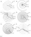
- Fig. 2d shows the schematic representation of an inventive interface 12 between the materials 4 and 10, which here is designed in the form of concentric circles 28 around a common center point 26. This is comparable to the pattern created by a drop falling into a liquid.
- the elevations 32 of the flesh-colored material run along the lines of the illustrated concentric circles 28, and the depressions 34 of the flesh-colored material run between the lines. Furthermore, it is possible for the distance between two circles to gradually increase with increasing distance from the center point 26, and for the elevations 32 and depressions 34 along or between the circles to gradually become larger and/or wider towards the outside.
- Fig. 3a to c show the analogous schematic representations of possible designs to the Fig. 2 a to c, where possible positionings of teeth 2 are shown in the representation of the boundary layer 12.
- Fig. 3a and b takes the possible tooth size of tooth/gingiva parts to be manufactured from the center point 26 of the spiral line 24 (at Fig. 3a ) or the concentric circles 28 (at Fig. 3b ) outwards, i.e. towards the edge of the blank.
- the center point 26 is not located at the center of the interface 12, but rather shifted toward an edge of the blank. Smaller tooth sizes can be arranged particularly on the side of the center point 26 where there is less distance from the edge—the compressed side, so to speak. Larger tooth sizes, on the other hand, can be arranged on the stretched side.
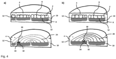
- Fig. 4a shows the design and arrangement of the interface 12 in a blank according to the invention in the design of a spiral 24 in a perspective view.
- the elevations 32 and depressions 34 of the flesh-colored material 10 are similar to those in Fig. 2 illustrated, wherein the tooth-colored material 4 can form the negative mold for the production of the flesh-colored material 10.
- the elevations 32 and depressions 34 of the flesh-colored material 10 alternate with one another.
- the elevations 32 form vertices, which are followed by slopes or inclined surfaces.
- the boundary surface 12 forms a chain line or a series of Us.
- the vertices or elevations 32 form concentric circles. The distance between the circles can be the same, but in the embodiment shown it is different, namely, for example, larger on the outside than on the inside.
- Fig. 4b shows the design and arrangement of the interface 12 in a blank according to the invention in the form of concentric circles 28 in perspective view.
- Fig. 4a shows the three-dimensional design, particularly comparable to a series of U's 30, of the flesh-colored material 10 at the interface between materials 4 and 10 is shown.
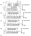
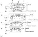
- Fig. 5 a to d show schematic sections through blanks according to the invention in perspective view in one embodiment each with possible placements of different virtual partial prostheses.
- Fig. 5a shows a mandibular anterior tooth segment from tooth 33 to 43
- Fig. 5b a maxillary anterior tooth segment from tooth 13 to 23
- Fig. 5c a disk, with a mandibular anterior tooth segment from tooth 31 to 33 and a maxillary anterior tooth segment from tooth 23 to 21 positioned next to each other.
- By rotating virtual tooth/gingiva parts by 180° (at Fig. 5d ) tooth segments from all four anterior tooth segments can be manufactured in the same blank. This does not only apply to anterior tooth segments as in Fig. 5a to c shown, but also for any other desired tooth segments that are to be manufactured from a blank.
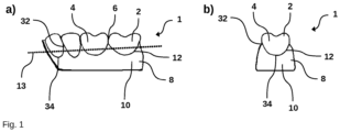
- FIG. 5a to 5c The plane 13, in which the interface 12 between the teeth made of tooth-colored material 4 and the denture base 8 made of flesh-colored material 10 lies, is shown in a side perspective as a straight line.
- Fig. 6 a to d show schematic representations of possible embodiments of a posterior tooth block in plan view, which is not part of the claimed invention. Possible positioning of teeth 2 or tooth/gingival parts, here in particular posterior teeth, in the boundary layer 12 between the tooth-colored material 4 and the flesh-colored material 10 are shown two-dimensionally.
- the fan-shaped orientation lines 38 converge with each other, and the central area formed by the lines can also be referred to as the convergence area 21.
- the orientation of the orientation lines 38 allows the selection of an appropriate size of the tooth/gingival part, depending on its placement in the block.
- Fig. 6a to d can be removed, tooth/gingiva parts that are worked out, in particular milled, in the upper area of the block automatically have smaller dimensions than tooth/gingiva parts that are worked out, in particular milled, at the bottom.
- Fig. 6b to d demonstrate that blocks according to the invention can be manufactured in different sizes to achieve even finer dimensioning adjustments. For example, it is possible to produce blocks in sizes "L” for very large tooth/gingiva parts, "M” for average-sized tooth/gingiva parts, and "S” for very small tooth/gingiva parts.
- an exemplary holder 36 which serves to clamp the block in the clamping device of the CAD/CAM device.
- Fig. 7 a to d show the schematic representations of possible designs of a block in Top view, which is not part of the claimed invention.
- Possible positioning of teeth 2 or tooth/gingiva parts, here in particular of front teeth, in the boundary layer 12 between the tooth-colored material 4 and the flesh-colored material 10 are drawn two-dimensionally. These sections are selected so that in Figures 8a to d the center point is below and the edge of the block is above the image.
- the orientation lines 38 shown in the block are thus sections of an imaginary spiral or imaginary concentric circles, which are considerably larger than the block.
- the orientation lines 38 serve to illustrate the increase in size of the section of the spiral 24 or the section of the concentric circles 28, which lie in the area of the block, from the center point 26 outwards, i.e.
- Fig. 7a can be removed, tooth-gingiva parts that are worked out, in particular milled, in the upper area of the block automatically have larger dimensions than tooth-gingiva parts that are worked out, in particular milled, in the lower area of the block.
- Fig. 7b to d show that blocks can be manufactured in different sizes, so that the three tooth-gingiva parts shown, which are in Fig. 7a can be placed on one block, also on individual blank blocks, which can be made from narrower blank blocks than the blank block.
- an exemplary web 36 is shown, which serves to clamp the block in the clamping device of the CAD/CAM device.
- Fig. 8 a to c show the schematic representations Possible designs of a block in plan view. Possible positioning of teeth 2 or tooth-gingiva parts, here in particular of posterior teeth, in the interface 12 between the tooth-colored material 4 and the flesh-colored material 10 are drawn two-dimensionally. These sections are selected so that in Figures 8a to c the center point is on the left side and the edge of the block is on the right side of the illustration.
- the course of the concentric circles 28 according to the invention, which lie in the inventive interface 12 between the materials 4 and 10, is drawn schematically in the form of dashed lines.
- the common center point 26 of the concentric circles 28 is on the left side of the blank in the illustration according to the figures.
- the distance between the concentric circles 28 increases in this design from the inside, i.e. from the side of the block on which the imaginary center point lies, to the outside, i.e. towards the edge of the blank.
- tooth-gingiva parts that are worked out, in particular milled, in the outer area of the block automatically have larger dimensions than tooth-gingiva parts that are worked out, in particular milled, near the center of the block.
- Fig. 8a to c further demonstrate that blocks according to the invention can be manufactured in different sizes to achieve even finer dimensioning adjustments.
- blocks according to the invention can be manufactured in different sizes to achieve even finer dimensioning adjustments.
- Fig. 8a to c is still an exemplary bridge 36 , which serves to clamp the block according to the invention in the clamping device of the CAD/CAM device.
- it is attached to the side where small tooth sizes can preferably be realized, i.e., near the imaginary center of the interface.
- Fig. 8d in combination with Fig. 8e clarifies that the block can also be oriented rotated.
- the web 36 which serves to clamp the blank according to the invention in the clamping device of the CAD/CAM device, is located in Fig. 8d on the other side of the blank than it is in the Fig. 8a until c is the case.
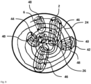
- Fig. 9 shows a schematic representation of a possible embodiment of a disc-shaped blank according to the invention in plan view. Positions of several tooth-gingiva parts, determined automatically and/or user-controlled by the control device, are shown in a blank according to the invention. In the present example, these virtual tooth-gingiva parts are partly oblique, partly radial, in the blank. Single-tooth gingiva segments 44 are provided, but any other type of tooth-gingiva parts is also possible.
- Fig. 9 Two- (48) and five-unit (46) tooth-gingiva parts are shown as examples.
- connecting bars 40 remain between the tooth-gingiva parts 1 to be produced and the remaining blank during the milling process, i.e., in the area of the milled joint 42, so that the tooth-gingiva parts 1 can be prevented from falling out during the milling process, even if the blank is rotated or tilted in three-dimensional space. This allows any conventional milling machine to be used for a blank according to the invention without requiring any further special modifications to the milling machine.
Landscapes
- Health & Medical Sciences (AREA)
- Oral & Maxillofacial Surgery (AREA)
- Dentistry (AREA)
- Epidemiology (AREA)
- Life Sciences & Earth Sciences (AREA)
- Animal Behavior & Ethology (AREA)
- General Health & Medical Sciences (AREA)
- Public Health (AREA)
- Veterinary Medicine (AREA)
- Engineering & Computer Science (AREA)
- Theoretical Computer Science (AREA)
- Physics & Mathematics (AREA)
- Water Supply & Treatment (AREA)
- Evolutionary Computation (AREA)
- Geometry (AREA)
- General Engineering & Computer Science (AREA)
- General Physics & Mathematics (AREA)
- Computer Hardware Design (AREA)
- Manufacturing & Machinery (AREA)
- Dental Prosthetics (AREA)
- Dental Tools And Instruments Or Auxiliary Dental Instruments (AREA)
Claims (10)
- Lingotin dentaire, avec une surface supérieure et une surface inférieure, qui est constitué d'un matériau de couleur chair (10) et d'un matériau de couleur dent (4), où le matériau de couleur chair (10) et le matériau de couleur dent (4) sont reliés entre eux et où l'interface (12) entre les matériaux (4, 10) avec des élévations (32) et des dépressions (34) formées dans ou sur l'interface (12) s'étend à travers un plan (13) éventuellement courbé, lequel plan (13) est parallèle ou incliné par rapport à au moins une partie des surfaces du lingotin, caractérisé en ce que les élévations (32) et les dépressions (34) sont formées chacune, en particulier au moins partiellement, de manière périphérique dans l'interface (12) entre les matériaux (4, 10), le sommet de chaque dépression (34) et/ou d'un relief (32) formant au moins une ligne (24, 25, 27, 28), où la ligne (24, 25, 27, 28) s'étend soit sous la forme d'une ou plusieurs spirales - arithmétiques ou logarithmiques - soit sous la forme d'un ou plusieurs cercles.
- Le lingotin selon la revendication 1, caractérisée en ce que la ligne (24, 25, 27, 28) présente un rayon r, vu depuis un centre (26), en particulier le centre du lingotin, où :


- Lingotin selon la revendication 1 ou 2, caractérisée en ce que le tracé des dépressions (34) et/ou des élévations (32) est la dérivée première de l'équation de la ligne (24, 25, 27, 28) de rayon r supérieur ou égal à zéro et augmente en particulier avec l'angle de rotation ϕ.
- Lingotin selon la revendication 2 ou 3, caractérisée en ce que le tracé des dépressions (34) et/ou des élévations (32) présente la forme de cercles concentriques (28).
- Lingotin selon l'une des revendications précédentes, caractérisée en ce que le tracé des élévations (32) et des dépressions (34) est plus rapproché près du centre (26) du lingotin et plus écarté vers l'extérieur, ou en ce que le tracé des élévations (32) et des dépressions (34) est plus écarté près du centre (26) du lingotin et plus rapproché vers l'extérieur.
- Lingotin selon l'une des revendications précédentes, caractérisée en ce que le point central (26) de la ligne ou des lignes (24, 25, 27, 28) n'est pas situé au centre du plan (13) de l'interface (12) entre les matériaux (4, 10), mais est légèrement décalé vers un bord dans le plan (13) de l'interface (12) et/ou le tracé des élévations (32) et des dépressions (34) présente des distances différentes sur différents côtés du point central (26).
- Lingotin selon l'une des revendications précédentes, caractérisée en ce que le matériau de couleur dent (4) et/ou, éventuellement, le matériau de couleur chair (10) est conçu avec un dégradé de couleur et/ou devient de plus en plus transparent au fur et à mesure que la distance par rapport à l'interface (12) entre les matériaux (4, 10) augmente, en particulier de manière continue.
- Procédé de fabrication d'une prothèse dentaire partielle, en utilisant un dispositif CAD/CAM à partir d'un lingotin ou d'un bloc, qui est fabriqué avec une surface de disque supérieure et une surface de disque inférieure, qui est constitué d'un matériau de couleur chair (10) et d'un matériau de couleur dent (4), où le matériau de couleur chair (10) et le matériau de couleur dent (4) sont reliés entre eux et où l'interface (12) entre les matériaux (4, 10) avec des élévations (32) et des dépressions (34) formés dans l'interface (12) s'étend à travers un plan (13), lequel plan (13) est parallèle ou courbé ou incliné par rapport à l'une des surfaces de disque du lingotin ou du bloc, caractérisé, en ce qu'une zone est réservée dans le lingotin ou le bloc pour au moins une prothèse partielle, qui s'étend sur une ou plusieurs saillies (32) et dépressions (34), et en ce que les saillies (32) et les dépressions (34) sont formés chacun, en particulier au moins partiellement, de manière périphérique dans l'interface (12) entre les matériaux (4, 10), où chaque sommet d'une dépression (34) et/ou d'une élévation (32) forme au moins une ligne (24, 25, 27, 28), la ligne (24, 25, 27, 28) s'étendant soit sous la forme d'une ou de plusieurs spirales - arithmétiques ou logarithmiques - soit sous la forme d'un ou de plusieurs ronds et une pluralité de prothèses partielles étant fabriquées à partir du lingotin.
- Procédé de fabrication d'une prothèse dentaire partielle selon la revendication 8, caractérisé en ce que le lingotin comporte des points de référence pour le positionnement dans le dispositif CAD/CAM et/ou un signe d'identification individuel, tel qu'un code QR ou une étiquette RFID, et/ou en ce que le dispositif de commande mémorise pour chaque lingotin la position d'une prothèse fabriquée et détermine pour de nouvelles prothèses partielles à fabriquer, en particulier par un procédé de « nesting », un lingotin et/ou le positionnement sur un lingotin, afin d'obtenir une utilisation maximale de la matière première.
- Procédé selon la revendication 8, où le dispositif CAD/CAM détermine la prothèse partielle en ce qui concerne sa forme spatiale, et présente un dispositif de commande qui, en fonction de la taille et de la largeur de dent souhaitée, positionne la prothèse partielle de cette manière dans le lingotin, et propose également en particulier la forme individuelle des dents, la rotation et/ou l'angulation des dents et les détermine - éventuellement après intervention de l'utilisateur.
Priority Applications (8)
| Application Number | Priority Date | Filing Date | Title |
|---|---|---|---|
| ES21190667T ES3037812T3 (en) | 2021-08-10 | 2021-08-10 | Dental blank and method for manufacturing a dental partial prosthesis |
| EP25187709.8A EP4603056A3 (fr) | 2021-08-10 | 2021-08-10 | Ébauche dentaire et procédé de fabrication d'une prothèse dentaire partielle |
| EP21190667.2A EP4134041B8 (fr) | 2021-08-10 | 2021-08-10 | Ébauche dentaire et procédé de production d'une prothèse partielle dentaire |
| CA3169200A CA3169200A1 (fr) | 2021-08-10 | 2022-07-29 | Ebauche dentaire, prothese dentaire partielle et methode de fabrication d'une prothese dentaire partielle |
| CN202210904082.7A CN115702835B (zh) | 2021-08-10 | 2022-07-29 | 牙科坯料、牙科局部义齿及制造牙科局部义齿的方法 |
| JP2022125963A JP2023025690A (ja) | 2021-08-10 | 2022-08-05 | 歯科用ブランク、部分義歯、ならびに部分義歯の製造方法 |
| US17/817,950 US12076201B2 (en) | 2021-08-10 | 2022-08-05 | Dental blank, dental partial prosthesis and method of manufacturing a dental partial prosthesis |
| KR1020220099017A KR20230023588A (ko) | 2021-08-10 | 2022-08-09 | 치과용 블랭크, 치과용 부분 보철물 및 치과용 부분 보철물의 제조 방법 |
Applications Claiming Priority (1)
| Application Number | Priority Date | Filing Date | Title |
|---|---|---|---|
| EP21190667.2A EP4134041B8 (fr) | 2021-08-10 | 2021-08-10 | Ébauche dentaire et procédé de production d'une prothèse partielle dentaire |
Related Child Applications (2)
| Application Number | Title | Priority Date | Filing Date |
|---|---|---|---|
| EP25187709.8A Division-Into EP4603056A3 (fr) | 2021-08-10 | 2021-08-10 | Ébauche dentaire et procédé de fabrication d'une prothèse dentaire partielle |
| EP25187709.8A Division EP4603056A3 (fr) | 2021-08-10 | 2021-08-10 | Ébauche dentaire et procédé de fabrication d'une prothèse dentaire partielle |
Publications (3)
| Publication Number | Publication Date |
|---|---|
| EP4134041A1 EP4134041A1 (fr) | 2023-02-15 |
| EP4134041B1 true EP4134041B1 (fr) | 2025-07-09 |
| EP4134041B8 EP4134041B8 (fr) | 2025-09-17 |
Family
ID=77300771
Family Applications (2)
| Application Number | Title | Priority Date | Filing Date |
|---|---|---|---|
| EP21190667.2A Active EP4134041B8 (fr) | 2021-08-10 | 2021-08-10 | Ébauche dentaire et procédé de production d'une prothèse partielle dentaire |
| EP25187709.8A Pending EP4603056A3 (fr) | 2021-08-10 | 2021-08-10 | Ébauche dentaire et procédé de fabrication d'une prothèse dentaire partielle |
Family Applications After (1)
| Application Number | Title | Priority Date | Filing Date |
|---|---|---|---|
| EP25187709.8A Pending EP4603056A3 (fr) | 2021-08-10 | 2021-08-10 | Ébauche dentaire et procédé de fabrication d'une prothèse dentaire partielle |
Country Status (7)
| Country | Link |
|---|---|
| US (1) | US12076201B2 (fr) |
| EP (2) | EP4134041B8 (fr) |
| JP (1) | JP2023025690A (fr) |
| KR (1) | KR20230023588A (fr) |
| CN (1) | CN115702835B (fr) |
| CA (1) | CA3169200A1 (fr) |
| ES (1) | ES3037812T3 (fr) |
Families Citing this family (3)
| Publication number | Priority date | Publication date | Assignee | Title |
|---|---|---|---|---|
| EP3597143B1 (fr) * | 2018-07-16 | 2021-07-07 | Ivoclar Vivadent AG | Prothèse dentaire |
| EP4545043A1 (fr) * | 2023-10-27 | 2025-04-30 | Ivoclar Vivadent AG | Procédé de détermination d'une structure interne d'une base de prothèse dentaire, procédé de fabrication d'une base de prothèse dentaire, base de prothèse dentaire, dispositif de traitement de données, programme informatique et support lisible par ordinateur |
| KR20250100245A (ko) | 2023-12-26 | 2025-07-03 | (주)룰루즈 | 인공치아 및 틀니 제조를 위한 일체형 블록 타입의 치과용 의료기기와 그 제조방법 |
Citations (1)
| Publication number | Priority date | Publication date | Assignee | Title |
|---|---|---|---|---|
| US20180104031A1 (en) * | 2016-10-19 | 2018-04-19 | Dentsply Sirona Inc. | Method for the production of a dental restoration |
Family Cites Families (7)
| Publication number | Priority date | Publication date | Assignee | Title |
|---|---|---|---|---|
| DE837288C (de) | 1949-12-08 | 1952-04-21 | Dr August Dueppers | Verfahren zur Herstellung von Zahnprothesen |
| US4970032A (en) | 1989-05-12 | 1990-11-13 | Rotsaert Henri L | Processes for the manufacture of artificial teeth and crowns |
| WO1991007141A1 (fr) | 1989-11-20 | 1991-05-30 | Wolfgang Becker | Procede de fabrication d'une prothese dentaire |
| DE102005055526A1 (de) | 2005-11-22 | 2007-06-06 | BEGO Bremer Goldschlägerei Wilh. Herbst GmbH & Co. KG | Verfahren und System zum Erzeugen einer dentalen Prothese |
| WO2013072287A1 (fr) * | 2011-11-15 | 2013-05-23 | Kronacher Werkzeugbau Klug Gmbh & Co. Kg | Ébauche de dent artificielle présentant plusieurs couches de couleurs différentes et son procédé de fabrication |
| DK3064170T3 (da) * | 2015-03-04 | 2021-08-23 | Ivoclar Vivadent Ag | Dentalt proteseråemne og fremgangsmåde til fremstilling af en dental protese |
| JP5964533B1 (ja) * | 2015-08-31 | 2016-08-03 | 株式会社松風 | 貫通孔を有する歯科用被切削体から歯科修復物を製造する歯科修復物製造システム、該システムの動作方法、該システム用プログラム、及び、該システムで使用する歯科用被切削体 |
-
2021
- 2021-08-10 ES ES21190667T patent/ES3037812T3/es active Active
- 2021-08-10 EP EP21190667.2A patent/EP4134041B8/fr active Active
- 2021-08-10 EP EP25187709.8A patent/EP4603056A3/fr active Pending
-
2022
- 2022-07-29 CA CA3169200A patent/CA3169200A1/fr active Pending
- 2022-07-29 CN CN202210904082.7A patent/CN115702835B/zh active Active
- 2022-08-05 JP JP2022125963A patent/JP2023025690A/ja active Pending
- 2022-08-05 US US17/817,950 patent/US12076201B2/en active Active
- 2022-08-09 KR KR1020220099017A patent/KR20230023588A/ko active Pending
Patent Citations (1)
| Publication number | Priority date | Publication date | Assignee | Title |
|---|---|---|---|---|
| US20180104031A1 (en) * | 2016-10-19 | 2018-04-19 | Dentsply Sirona Inc. | Method for the production of a dental restoration |
Also Published As
| Publication number | Publication date |
|---|---|
| JP2023025690A (ja) | 2023-02-22 |
| EP4134041B8 (fr) | 2025-09-17 |
| KR20230023588A (ko) | 2023-02-17 |
| US12076201B2 (en) | 2024-09-03 |
| EP4134041A1 (fr) | 2023-02-15 |
| US20230045917A1 (en) | 2023-02-16 |
| EP4603056A2 (fr) | 2025-08-20 |
| CN115702835B (zh) | 2026-03-10 |
| ES3037812T3 (en) | 2025-10-07 |
| CN115702835A (zh) | 2023-02-17 |
| CA3169200A1 (fr) | 2023-02-10 |
| EP4603056A3 (fr) | 2025-10-22 |
Similar Documents
| Publication | Publication Date | Title |
|---|---|---|
| EP3064170B1 (fr) | Ebauche de prothèse dentaire et procédé de fabrication d'une prothèse dentaire | |
| EP4134041B1 (fr) | Ébauche dentaire et procédé de production d'une prothèse partielle dentaire | |
| EP2111180B1 (fr) | Procédé concernant la modélisation et la fabrication d'un dentier ou de sa base | |
| EP1603481B1 (fr) | Procede de production automatique d'une superstructure dentaire pour assurer la jonction avec un implant | |
| EP3021783B1 (fr) | Support de superstructure et un procédé pour le fabriquer | |
| EP3597143B1 (fr) | Prothèse dentaire | |
| EP2838465B1 (fr) | Procédé de production d'un dentier | |
| EP3128945B1 (fr) | Ébauche de base de prothèse préformée | |
| EP2996626B1 (fr) | Prothèses dentaires | |
| EP3612131B1 (fr) | Procédé de fabrication d'une prothèse dentaire à racines parallèles des dents de la prothèse | |
| DE102017113814A1 (de) | Verfahren zur Herstellung einer Dentalprothese mit definiertem Klebespalt | |
| EP3200720B1 (fr) | Moule pour la préparation d'une ébauche preformée d'une base de prothèse | |
| EP3496656B1 (fr) | Procédé pour la production d'une prothèse ou d'une prothèse partielle | |
| EP1905379B1 (fr) | Methode pour construire un connecteur | |
| EP4134042B1 (fr) | Ébauche dentaire et fabrication d'une prothèse dentaire partielle à partir d'une ébauche dentaire | |
| EP3669818A1 (fr) | Ébauche multicolore dentaire | |
| EP3852677A1 (fr) | Demi-produit pour la fabrication de dents prothétiques et procédé pour sa fabrication et son traitement | |
| EP3445274B1 (fr) | Courbure de pas de dent et procede de production d'une courbure de pas de dent | |
| EP3525718B1 (fr) | Ébauche de plaque-base de prothèse préformée prise dans de la cire | |
| EP3923854B1 (fr) | Ébauche servant à la fabrication d'une restauration dentaire, et procédé pour sa fabrication | |
| DE10304802A1 (de) | Zahnimplantat sowie Verfahren zum Herstellen von Zahnersatz unter Verwendung eines Zahnimplantats | |
| EP3064169B1 (fr) | Procédé de fabrication de pièces céramiques dentaires et appareils pour la fabrication de pièces de céramique dentaire | |
| EP3125819B1 (fr) | Procédé de fabrication d'une couronne dentaire prothétique, couronne dentaire et couverture dentaire utilisant cette couronne |
Legal Events
| Date | Code | Title | Description |
|---|---|---|---|
| PUAI | Public reference made under article 153(3) epc to a published international application that has entered the european phase |
Free format text: ORIGINAL CODE: 0009012 |
|
| STAA | Information on the status of an ep patent application or granted ep patent |
Free format text: STATUS: THE APPLICATION HAS BEEN PUBLISHED |
|
| AK | Designated contracting states |
Kind code of ref document: A1 Designated state(s): AL AT BE BG CH CY CZ DE DK EE ES FI FR GB GR HR HU IE IS IT LI LT LU LV MC MK MT NL NO PL PT RO RS SE SI SK SM TR |
|
| STAA | Information on the status of an ep patent application or granted ep patent |
Free format text: STATUS: REQUEST FOR EXAMINATION WAS MADE |
|
| 17P | Request for examination filed |
Effective date: 20230811 |
|
| RBV | Designated contracting states (corrected) |
Designated state(s): AL AT BE BG CH CY CZ DE DK EE ES FI FR GB GR HR HU IE IS IT LI LT LU LV MC MK MT NL NO PL PT RO RS SE SI SK SM TR |
|
| STAA | Information on the status of an ep patent application or granted ep patent |
Free format text: STATUS: EXAMINATION IS IN PROGRESS |
|
| 17Q | First examination report despatched |
Effective date: 20240313 |
|
| GRAP | Despatch of communication of intention to grant a patent |
Free format text: ORIGINAL CODE: EPIDOSNIGR1 |
|
| STAA | Information on the status of an ep patent application or granted ep patent |
Free format text: STATUS: GRANT OF PATENT IS INTENDED |
|
| INTG | Intention to grant announced |
Effective date: 20250203 |
|
| RIN1 | Information on inventor provided before grant (corrected) |
Inventor name: WATZKE, RONNY |
|
| GRAS | Grant fee paid |
Free format text: ORIGINAL CODE: EPIDOSNIGR3 |
|
| GRAA | (expected) grant |
Free format text: ORIGINAL CODE: 0009210 |
|
| STAA | Information on the status of an ep patent application or granted ep patent |
Free format text: STATUS: THE PATENT HAS BEEN GRANTED |
|
| P01 | Opt-out of the competence of the unified patent court (upc) registered |
Free format text: CASE NUMBER: APP_21248/2025 Effective date: 20250505 |
|
| AK | Designated contracting states |
Kind code of ref document: B1 Designated state(s): AL AT BE BG CH CY CZ DE DK EE ES FI FR GB GR HR HU IE IS IT LI LT LU LV MC MK MT NL NO PL PT RO RS SE SI SK SM TR |
|
| REG | Reference to a national code |
Ref country code: GB Ref legal event code: FG4D Free format text: NOT ENGLISH |
|
| REG | Reference to a national code |
Ref country code: CH Ref legal event code: EP |
|
| REG | Reference to a national code |
Ref country code: IE Ref legal event code: FG4D Free format text: LANGUAGE OF EP DOCUMENT: GERMAN |
|
| REG | Reference to a national code |
Ref country code: DE Ref legal event code: R096 Ref document number: 502021007946 Country of ref document: DE |
|
| GRAT | Correction requested after decision to grant or after decision to maintain patent in amended form |
Free format text: ORIGINAL CODE: EPIDOSNCDEC |
|
| REG | Reference to a national code |
Ref country code: CH Ref legal event code: PK Free format text: BERICHTIGUNGEN |
|
| REG | Reference to a national code |
Ref country code: NL Ref legal event code: FP |
|
| REG | Reference to a national code |
Ref country code: CH Ref legal event code: PK Free format text: BERICHTIGUNG B8 |
|
| RIN2 | Information on inventor provided after grant (corrected) |
Inventor name: WATZKE, RONNY |
|
| PGFP | Annual fee paid to national office [announced via postgrant information from national office to epo] |
Ref country code: NL Payment date: 20250821 Year of fee payment: 5 |
|
| REG | Reference to a national code |
Ref country code: ES Ref legal event code: FG2A Ref document number: 3037812 Country of ref document: ES Kind code of ref document: T3 Effective date: 20251007 |
|
| PGFP | Annual fee paid to national office [announced via postgrant information from national office to epo] |
Ref country code: ES Payment date: 20250904 Year of fee payment: 5 |
|
| PGFP | Annual fee paid to national office [announced via postgrant information from national office to epo] |
Ref country code: DE Payment date: 20250820 Year of fee payment: 5 |
|
| PGFP | Annual fee paid to national office [announced via postgrant information from national office to epo] |
Ref country code: GB Payment date: 20250828 Year of fee payment: 5 |
|
| PGFP | Annual fee paid to national office [announced via postgrant information from national office to epo] |
Ref country code: FR Payment date: 20250828 Year of fee payment: 5 Ref country code: AT Payment date: 20251020 Year of fee payment: 5 |
|
| PGFP | Annual fee paid to national office [announced via postgrant information from national office to epo] |
Ref country code: CH Payment date: 20250918 Year of fee payment: 5 |
|
| PG25 | Lapsed in a contracting state [announced via postgrant information from national office to epo] |
Ref country code: PT Free format text: LAPSE BECAUSE OF FAILURE TO SUBMIT A TRANSLATION OF THE DESCRIPTION OR TO PAY THE FEE WITHIN THE PRESCRIBED TIME-LIMIT Effective date: 20251110 |
|
| PG25 | Lapsed in a contracting state [announced via postgrant information from national office to epo] |
Ref country code: IS Free format text: LAPSE BECAUSE OF FAILURE TO SUBMIT A TRANSLATION OF THE DESCRIPTION OR TO PAY THE FEE WITHIN THE PRESCRIBED TIME-LIMIT Effective date: 20251109 |
|
| PG25 | Lapsed in a contracting state [announced via postgrant information from national office to epo] |
Ref country code: NO Free format text: LAPSE BECAUSE OF FAILURE TO SUBMIT A TRANSLATION OF THE DESCRIPTION OR TO PAY THE FEE WITHIN THE PRESCRIBED TIME-LIMIT Effective date: 20251009 |
|
| REG | Reference to a national code |
Ref country code: LT Ref legal event code: MG9D |
|
| PG25 | Lapsed in a contracting state [announced via postgrant information from national office to epo] |
Ref country code: FI Free format text: LAPSE BECAUSE OF FAILURE TO SUBMIT A TRANSLATION OF THE DESCRIPTION OR TO PAY THE FEE WITHIN THE PRESCRIBED TIME-LIMIT Effective date: 20250709 |
|
| PG25 | Lapsed in a contracting state [announced via postgrant information from national office to epo] |
Ref country code: HR Free format text: LAPSE BECAUSE OF FAILURE TO SUBMIT A TRANSLATION OF THE DESCRIPTION OR TO PAY THE FEE WITHIN THE PRESCRIBED TIME-LIMIT Effective date: 20250709 |
|
| PG25 | Lapsed in a contracting state [announced via postgrant information from national office to epo] |
Ref country code: GR Free format text: LAPSE BECAUSE OF FAILURE TO SUBMIT A TRANSLATION OF THE DESCRIPTION OR TO PAY THE FEE WITHIN THE PRESCRIBED TIME-LIMIT Effective date: 20251010 |
|
| PG25 | Lapsed in a contracting state [announced via postgrant information from national office to epo] |
Ref country code: SE Free format text: LAPSE BECAUSE OF FAILURE TO SUBMIT A TRANSLATION OF THE DESCRIPTION OR TO PAY THE FEE WITHIN THE PRESCRIBED TIME-LIMIT Effective date: 20250709 |
|
| PG25 | Lapsed in a contracting state [announced via postgrant information from national office to epo] |
Ref country code: LV Free format text: LAPSE BECAUSE OF FAILURE TO SUBMIT A TRANSLATION OF THE DESCRIPTION OR TO PAY THE FEE WITHIN THE PRESCRIBED TIME-LIMIT Effective date: 20250709 |
|
| PG25 | Lapsed in a contracting state [announced via postgrant information from national office to epo] |
Ref country code: BG Free format text: LAPSE BECAUSE OF FAILURE TO SUBMIT A TRANSLATION OF THE DESCRIPTION OR TO PAY THE FEE WITHIN THE PRESCRIBED TIME-LIMIT Effective date: 20250709 Ref country code: PL Free format text: LAPSE BECAUSE OF FAILURE TO SUBMIT A TRANSLATION OF THE DESCRIPTION OR TO PAY THE FEE WITHIN THE PRESCRIBED TIME-LIMIT Effective date: 20250709 |
|
| PG25 | Lapsed in a contracting state [announced via postgrant information from national office to epo] |
Ref country code: RS Free format text: LAPSE BECAUSE OF FAILURE TO SUBMIT A TRANSLATION OF THE DESCRIPTION OR TO PAY THE FEE WITHIN THE PRESCRIBED TIME-LIMIT Effective date: 20251009 |
|
| PG25 | Lapsed in a contracting state [announced via postgrant information from national office to epo] |
Ref country code: RO Free format text: LAPSE BECAUSE OF FAILURE TO SUBMIT A TRANSLATION OF THE DESCRIPTION OR TO PAY THE FEE WITHIN THE PRESCRIBED TIME-LIMIT Effective date: 20250709 |
|
| PG25 | Lapsed in a contracting state [announced via postgrant information from national office to epo] |
Ref country code: SM Free format text: LAPSE BECAUSE OF FAILURE TO SUBMIT A TRANSLATION OF THE DESCRIPTION OR TO PAY THE FEE WITHIN THE PRESCRIBED TIME-LIMIT Effective date: 20250709 |
|
| PG25 | Lapsed in a contracting state [announced via postgrant information from national office to epo] |
Ref country code: DK Free format text: LAPSE BECAUSE OF FAILURE TO SUBMIT A TRANSLATION OF THE DESCRIPTION OR TO PAY THE FEE WITHIN THE PRESCRIBED TIME-LIMIT Effective date: 20250709 |
|
| PG25 | Lapsed in a contracting state [announced via postgrant information from national office to epo] |
Ref country code: LU Free format text: LAPSE BECAUSE OF NON-PAYMENT OF DUE FEES Effective date: 20250810 |
|
| PG25 | Lapsed in a contracting state [announced via postgrant information from national office to epo] |
Ref country code: CZ Free format text: LAPSE BECAUSE OF FAILURE TO SUBMIT A TRANSLATION OF THE DESCRIPTION OR TO PAY THE FEE WITHIN THE PRESCRIBED TIME-LIMIT Effective date: 20250709 |
|
| PG25 | Lapsed in a contracting state [announced via postgrant information from national office to epo] |
Ref country code: SK Free format text: LAPSE BECAUSE OF FAILURE TO SUBMIT A TRANSLATION OF THE DESCRIPTION OR TO PAY THE FEE WITHIN THE PRESCRIBED TIME-LIMIT Effective date: 20250709 |