EP4134277A1 - Procédé de réglage de la luminosité, appareil, et support de stockage de multiples sources de lumière d'éclairage - Google Patents
Procédé de réglage de la luminosité, appareil, et support de stockage de multiples sources de lumière d'éclairage Download PDFInfo
- Publication number
- EP4134277A1 EP4134277A1 EP22189992.5A EP22189992A EP4134277A1 EP 4134277 A1 EP4134277 A1 EP 4134277A1 EP 22189992 A EP22189992 A EP 22189992A EP 4134277 A1 EP4134277 A1 EP 4134277A1
- Authority
- EP
- European Patent Office
- Prior art keywords
- brightness
- illumination light
- adjusting
- brightness adjusting
- user
- Prior art date
- Legal status (The legal status is an assumption and is not a legal conclusion. Google has not performed a legal analysis and makes no representation as to the accuracy of the status listed.)
- Withdrawn
Links
Images



Classifications
-
- G—PHYSICS
- G06—COMPUTING OR CALCULATING; COUNTING
- G06F—ELECTRIC DIGITAL DATA PROCESSING
- G06F3/00—Input arrangements for transferring data to be processed into a form capable of being handled by the computer; Output arrangements for transferring data from processing unit to output unit, e.g. interface arrangements
- G06F3/01—Input arrangements or combined input and output arrangements for interaction between user and computer
- G06F3/048—Interaction techniques based on graphical user interfaces [GUI]
- G06F3/0484—Interaction techniques based on graphical user interfaces [GUI] for the control of specific functions or operations, e.g. selecting or manipulating an object, an image or a displayed text element, setting a parameter value or selecting a range
- G06F3/04847—Interaction techniques to control parameter settings, e.g. interaction with sliders or dials
-
- H—ELECTRICITY
- H05—ELECTRIC TECHNIQUES NOT OTHERWISE PROVIDED FOR
- H05B—ELECTRIC HEATING; ELECTRIC LIGHT SOURCES NOT OTHERWISE PROVIDED FOR; CIRCUIT ARRANGEMENTS FOR ELECTRIC LIGHT SOURCES, IN GENERAL
- H05B47/00—Circuit arrangements for operating light sources in general, i.e. where the type of light source is not relevant
- H05B47/10—Controlling the light source
- H05B47/105—Controlling the light source in response to determined parameters
-
- B—PERFORMING OPERATIONS; TRANSPORTING
- B60—VEHICLES IN GENERAL
- B60Q—ARRANGEMENT OF SIGNALLING OR LIGHTING DEVICES, THE MOUNTING OR SUPPORTING THEREOF OR CIRCUITS THEREFOR, FOR VEHICLES IN GENERAL
- B60Q3/00—Arrangement of lighting devices for vehicle interiors; Lighting devices specially adapted for vehicle interiors
- B60Q3/80—Circuits; Control arrangements
- B60Q3/82—Switches specially adapted for vehicle interior lighting, e.g. switching by tilting the lens
-
- B—PERFORMING OPERATIONS; TRANSPORTING
- B60—VEHICLES IN GENERAL
- B60Q—ARRANGEMENT OF SIGNALLING OR LIGHTING DEVICES, THE MOUNTING OR SUPPORTING THEREOF OR CIRCUITS THEREFOR, FOR VEHICLES IN GENERAL
- B60Q3/00—Arrangement of lighting devices for vehicle interiors; Lighting devices specially adapted for vehicle interiors
- B60Q3/80—Circuits; Control arrangements
- B60Q3/85—Circuits; Control arrangements for manual control of the light, e.g. of colour, orientation or intensity
-
- G—PHYSICS
- G06—COMPUTING OR CALCULATING; COUNTING
- G06F—ELECTRIC DIGITAL DATA PROCESSING
- G06F3/00—Input arrangements for transferring data to be processed into a form capable of being handled by the computer; Output arrangements for transferring data from processing unit to output unit, e.g. interface arrangements
- G06F3/01—Input arrangements or combined input and output arrangements for interaction between user and computer
- G06F3/048—Interaction techniques based on graphical user interfaces [GUI]
- G06F3/0487—Interaction techniques based on graphical user interfaces [GUI] using specific features provided by the input device, e.g. functions controlled by the rotation of a mouse with dual sensing arrangements, or of the nature of the input device, e.g. tap gestures based on pressure sensed by a digitiser
- G06F3/0488—Interaction techniques based on graphical user interfaces [GUI] using specific features provided by the input device, e.g. functions controlled by the rotation of a mouse with dual sensing arrangements, or of the nature of the input device, e.g. tap gestures based on pressure sensed by a digitiser using a touch-screen or digitiser, e.g. input of commands through traced gestures
-
- G—PHYSICS
- G06—COMPUTING OR CALCULATING; COUNTING
- G06F—ELECTRIC DIGITAL DATA PROCESSING
- G06F9/00—Arrangements for program control, e.g. control units
- G06F9/06—Arrangements for program control, e.g. control units using stored programs, i.e. using an internal store of processing equipment to receive or retain programs
- G06F9/44—Arrangements for executing specific programs
- G06F9/451—Execution arrangements for user interfaces
-
- H—ELECTRICITY
- H05—ELECTRIC TECHNIQUES NOT OTHERWISE PROVIDED FOR
- H05B—ELECTRIC HEATING; ELECTRIC LIGHT SOURCES NOT OTHERWISE PROVIDED FOR; CIRCUIT ARRANGEMENTS FOR ELECTRIC LIGHT SOURCES, IN GENERAL
- H05B47/00—Circuit arrangements for operating light sources in general, i.e. where the type of light source is not relevant
- H05B47/10—Controlling the light source
-
- B—PERFORMING OPERATIONS; TRANSPORTING
- B60—VEHICLES IN GENERAL
- B60Q—ARRANGEMENT OF SIGNALLING OR LIGHTING DEVICES, THE MOUNTING OR SUPPORTING THEREOF OR CIRCUITS THEREFOR, FOR VEHICLES IN GENERAL
- B60Q2500/00—Special features or arrangements of vehicle interior lamps
- B60Q2500/30—Arrangements for illuminating different zones in the vehicle, e.g. front/rear, different seats
-
- Y—GENERAL TAGGING OF NEW TECHNOLOGICAL DEVELOPMENTS; GENERAL TAGGING OF CROSS-SECTIONAL TECHNOLOGIES SPANNING OVER SEVERAL SECTIONS OF THE IPC; TECHNICAL SUBJECTS COVERED BY FORMER USPC CROSS-REFERENCE ART COLLECTIONS [XRACs] AND DIGESTS
- Y02—TECHNOLOGIES OR APPLICATIONS FOR MITIGATION OR ADAPTATION AGAINST CLIMATE CHANGE
- Y02B—CLIMATE CHANGE MITIGATION TECHNOLOGIES RELATED TO BUILDINGS, e.g. HOUSING, HOUSE APPLIANCES OR RELATED END-USER APPLICATIONS
- Y02B20/00—Energy efficient lighting technologies, e.g. halogen lamps or gas discharge lamps
- Y02B20/40—Control techniques providing energy savings, e.g. smart controller or presence detection
Definitions
- the present application relates to a technical field of human-computer interaction (HCI), and specifically, to a brightness adjusting method, an apparatus, and a storage medium for multi illumination light sources that support synchronously adjusting of a plurality of zonal illumination light sources.
- HCI human-computer interaction
- Illumination light sources in an interior of a vehicle can provide required illumination for a driver and passengers.
- Physical buttons set next to the illumination light sources are generally used to control illumination switches in traditional vehicles.
- both the number of illumination light sources and their locations in a vehicle are increasing. Since drivers and passengers have different needs for brightness of the illumination light sources, zonal independent illumination has become a development trend.
- Zonal independent illumination can realize independent control of switches and adjustment of brightness respectively of illumination light sources within each area. As some vehicles even have six areas of independent illumination, more efficient operation methods are needed for the increasing brightness adjustment options.
- a common adjusting method is to group the illumination light sources directly, and present a switch button plus a brightness sliding bar on the screen or the control interface in the form of a list.
- FIG. 1 is a schematic diagram of a brightness adjusting method for multiple illumination light sources in an interior of an existing vehicle.
- the control interface is equipped with a global light switch button and a brightness sliding bar 11, a driver's illumination light switch button and a brightness sliding bar 12, a front passenger seat's illumination light switch button and a brightness sliding bar 13, a left back seat's illumination light switch button and a brightness sliding bar 14, and a right back seat's illumination light switch button and a brightness sliding bar 15.
- the present application is to provide a brightness adjusting method, an apparatus, and a storage medium for multiple illumination light sources, which can simplify operation complexity of adjusting illumination light sources and support synchronously adjusting of a plurality of zonal illumination light sources.
- a brightness adjusting method of multiple illumination light sources is provided in a first embodiment of the present application, which is applied to an interior of a vehicle.
- the brightness adjusting method comprises: constructing at least one lamp group adjusting hot area used for brightness adjusting triggering on a touchable brightness adjusting interface; wherein the lamp group adjusting hot area comprises a plurality of sub-control hot areas and a total control hot area; each of the sub-control hot areas is used to adjust at least one of the multi illumination light sources, and the total control hot area is used to adjust all illumination light sources; recording a click position of a user's finger clicking on the touchable brightness adjusting interface, obtaining a target lamp group adjusting hot area where the click position is located, and continuously detecting and recording a current position of the user's finger before the user's finger is lifted; and performing switching of switch states and brightness adjusting of a target illumination light source corresponding to the target lamp group adjusting hot area according to the current position.
- a brightness adjusting apparatus for multiple illumination light sources is provided in a second embodiment of the present application, which is applied to an interior of a vehicle.
- the brightness adjusting apparatus comprises: a touchable brightness adjusting interface; a plurality of lamp group adjusting hot areas constructed on the touchable brightness adjusting interface and used for brightness adjusting triggering; wherein the lamp group adjusting hot areas comprise a plurality of sub-control hot areas and a total control hot area; each of the sub-control hot areas is used to adjust at least one of the multi illumination light sources, and the total control hot area is used to adjust all illumination light sources; a detecting module used for recording a click position of a user's finger clicking on the touchable brightness adjusting interface, obtaining a target lamp group adjusting hot area where the click position is located, and continuously detecting and recording a current position of the user's finger before the user's finger is lifted; and an adjusting module used for performing switching of switch states and brightness adjusting of a target illumination light source corresponding to
- a computer readable storage medium stores computer executable program codes, and the program codes implement the steps of the above-mentioned brightness adjusting method when executed by a processor.
- the brightness adjusting method for multi illumination light sources provided in the embodiments of the present application can realize zonal independent illumination in a plurality of areas in the interior of a vehicle.
- the zonal independent illumination can realize independent control of switches and adjustment of brightness respectively of illumination light sources in each area; and the touchable brightness adjusting interface is simple, the touch operation is intuitive, simple, and efficient, and intuitive blind operation can be realized.
- the brightness adjusting method provided in the present application is more in line with a user's behaviors, and a control interface is more concise and understandable.
- the present application can support switching of switch states and brightness adjusting of multiple illumination light sources at the same time.
- a brightness adjusting method for multi illumination light sources based on a HCI mode on a touchable brightness adjusting interface is provided in the present application.
- the brightness adjusting method provided in the present application is more in line with a user's behaviors, and the touchable brightness adjusting interface is more concise and understandable.
- the present application can support switching of switch states and brightness adjusting of multiple illumination light sources at the same time.
- Application fields of the brightness adjusting method for multi illumination light sources include, but not limited to, brightness adjusting of multi illumination light sources in scenes such as cars, sport utility vehicles (SUVs), trucks, coaches, and aircraft cockpits.
- the present application can be quickly deployed in various areas such as vehicles' central control screens, armrests, seat sides, portable touchable mobile devices and the like, and support an intuitive blind operation.
- FIG. 2 is a flowchart of the brightness adjusting method for multi illumination light sources provided in the embodiments of the present application.
- the brightness adjusting method in the embodiments includes the following steps: S21: constructing at least one lamp group adjusting hot area used for brightness adjusting triggering on the touchable brightness adjusting interface; S22: recording a click position of a user's finger clicking on the touchable brightness adjusting interface, obtaining a target lamp group adjusting hot area where the click position is located, and continuously detecting and recording a current position of the user's finger before the user's finger is lifted; and S23: performing switching of switch states and brightness adjusting of a target illumination light source corresponding to the target lamp group adjusting hot area according to the current position.
- S21 constructing at least one lamp group adjusting hot area used for brightness adjusting triggering on the touchable brightness adjusting interface
- S22 recording a click position of a user's finger clicking on the touchable brightness adjusting interface, obtaining a target lamp group adjusting hot area where the click position is located
- Step S21 constructing at least one lamp group adjusting hot area used for brightness adjusting triggering on the touchable brightness adjusting interface.
- the lamp group adjusting hot area includes a plurality of sub-control hot areas and a total control hot area.
- Each of the sub-control hot areas is used to adjust at least one of the multi illumination light sources, and the total control hot area is used to adjust all illumination light sources. That is, as a brightness controller of a corresponding illumination light source, the sub-control hot area is used to control switch states of the corresponding illumination light source and adjust a corresponding brightness value.
- the total control hot area is used to unifiedly control switch states of all illumination light sources and unifiedly adjust corresponding brightness values.
- the touchable brightness adjusting interface can be a touch display screen in a car or a touch display screen of a mobile device, or other interfaces that can provide touch operations.
- the touchable brightness adjusting interface is deployed in various areas such as vehicles' central control screens, armrests, seat sides, portable touch mobile devices and the like.
- the lamp group adjusting hot area is established based on a down-scaled top view of an interior layout of the vehicle (i.e., a reduced scale representation which is proportional to the reality).
- a controllable area of each sub-control hot area is adapted to a target illumination area of a corresponding illumination light source, for example, shapes are similar and sizes are proportional. So that touch of the sub-control hot area can truly reflect a target illumination light source that the user wants to manipulate.
- the lamp group adjusting hot area established based on a down-scaled top view of the interior layout of the vehicle on the touchable brightness adjusting interface 71 includes: the total control hot area T used as an unified switch of illumination light sources in the whole vehicle and used to unifiedly adjust brightness of the illumination light sources in the whole vehicle, a sub-control hot area A corresponding to a target illumination area of an illumination light source in a driver's area of the vehicle, a sub-control hot area B corresponding to a target illumination area of an illumination light source in a front passenger seat's area of the vehicle, a sub-control hot area C corresponding to a target illumination area of an illumination light source in a left back seat's area of the vehicle, and a sub-control hot area D corresponding to a target illumination area of an illumination light source
- the lamp group adjusting hot area further includes a sub-control hot area E corresponding to a target illumination area of an illumination light source in a central control area of the vehicle and a sub-control hot area F corresponding to a target illumination area of an illumination light source in a middle back seat's area of the vehicle.
- User's adjusting operations for the total control hot area T or the corresponding sub-control hot areas A to F are directly synchronized to brightness adjusting operations for the corresponding illumination light sources in the corresponding areas of the vehicle. That is, independent illumination in six areas in the vehicle can be realized. Independent control of switches and adjustment of brightness respectively of the illumination light source in each area can be realized through the zonal independent illumination.
- the touchable brightness adjusting interface is simple, and the touch operation is intuitive, simple, and efficient that intuitive blind operation can be realized.
- each sub-control hot area can be adjusted according to the layout of the touchable brightness adjusting interface and the number of controllable illumination light sources. According to the above-mentioned example of the double row seat model vehicle and the independent illumination in each seat area, those skilled in the art can also obtain implementations of the present application without creative efforts on two seat vehicles, three row seat vehicles, buses, and other vehicles.
- Each sub-control hot area is only used when the user determines an area it belongs to each time he clicks.
- a control mode of the total control hot area T can be multiplexed in a form of the total control sub-hot area T1 and the total control sub-hot area T2 for total control of a front row of all illumination light sources/a back row of all illumination light sources.
- some vehicle models may have more or less zonal independent illumination areas than the embodiment shown in FIG. 3 , and the touchable brightness adjusting interface can also be equipped with more or less lamp group adjusting hot areas.
- it can be set that only the total control hot area supports brightness adjusting by sliding, and other sub-control hot areas only respond to the switching operations of the switch states of the illumination light sources.
- Step S22 recording the click position of the user's finger clicking on the touchable brightness adjusting interface, obtaining the target lamp group adjusting hot area where the click position is located, and continuously detecting and recording the current position of the user's finger before the user's finger is lifted.
- a processor configured under the touchable brightness adjusting interface can detect and record the click position of the user's finger, and a controllable area range of the click position is calculated, so as to obtain the target lamp group adjusting hot area corresponding to the click position. And the processor is used to record the current position before the user's finger is lifted.
- the processor will record the click position, calculate and determine an illumination light source that the user wants to adjust, so that an adjusted signal can be sequentially transmitted to a corresponding illumination light source.
- the lamp group adjusting hot area is only used when determining the click position each time. If the user's finger does not slide before lifting, the switch states of the illumination light source which corresponds to a target lamp group adjusting hot area corresponding to the click position are controlled by switching after the user's finger is lifted, and its brightness value is not controlled/adjusted (that is, in this state, an on or off operation of the corresponding illumination light source will be performed only after the user's finger is lifted).
- the processor will adjust the corresponding brightness of a real-time illumination light source according to the sliding amount of the user's finger in real time (that is, in this state, if the user's finger is not lifted, the on or off operation of the corresponding illumination light source can also be triggered. Even if the user's finger returns to the click position, the brightness of the illumination light source will be adjusted and controlled continuously).
- Step S23 performing the switching of the switch states and the brightness adjusting of the target illumination light source corresponding to the target lamp group adjusting hot area according to the current position.
- the processor configured under the touchable brightness adjusting interface is used to detect and calculate the click position, and detect and calculate the current position before the user's finger is lifted.
- the processor When the user initiates the interactive operation, the processor will record the click position, calculate and determine the illumination light source that the user wants to adjust. If the user's finger does not slide before lifting (the current position is same as the click position), the switch states of the illumination light source which corresponds to the target lamp group adjusting hot area corresponding to the click position are controlled by switching after the user's finger is lifted, and its brightness value is not controlled/adjusted (that is, in this state, the on or off operation of the corresponding illumination light source will be performed only after the user's finger is lifted).
- the processor will adjust the corresponding brightness of the real-time illumination light source according to the sliding amount of the user's finger in real time (that is, in this state, if the user's finger is not lifted, the on or off operation of the corresponding illumination light source can also be triggered. Even if the user's finger returns to the click position, the brightness of the illumination light source will be adjusted and controlled continuously).
- the brightness adjustment for the target illumination light source can also be reflected in the target lamp group adjusting hot area corresponding to the touchable brightness adjusting interface in real time. For example, when the user clicks one lamp group adjusting hot area to turn on the target illumination light source, the lamp group adjusting hot area and the target illumination light source are lit up to a preset brightness value at the same time. When the user clicks one lamp group adjusting hot area and slides his finger to turn on and adjust the brightness of the target illumination light source, the lamp group adjusting hot area and the target illumination light source are lit up at the same time, and the brightness of the lamp group adjusting hot area and the brightness of the target illumination light source change in accordance with the sliding amount of a longitudinal coordinate of the current position, so as to improve intuitive and friendly handling.
- a light-emitting circuit controlled by a controller which is configured under the touchable brightness adjusting interface, is used to perform lighting/resting screen of the target lamp group adjusting hot area, and display current brightness in real time.
- the step S22 further includes: S221: recording position coordinates of the click position, and establishing a rectangular coordinate system with the position coordinates as a center point, wherein a longitudinal coordinate of the rectangular coordinate system is matched with a direction of a vehicle body; and S222: continuously detecting and recording the current position of the user's finger before the user's finger is lifted.
- the step 23 further includes: S231: synchronously performing the switching of the switch states of the target illumination light source when the current position is same as the click position and the user's finger is lifted.
- the target illumination light source is switched from the off state to the on state, and the brightness when it is turned on can be a preset brightness value (for example, it is the brightness value when it was turned off last time, which can be memorized and directly assigned to the target illumination light source when it is turned on this time).
- S232 turning on the target illumination light source when the current position is different from the click position, and adjusting the brightness of the target illumination light source synchronously and adaptively according to the sliding amount of the longitudinal coordinate of the current position.
- FIG. 4 A flowchart of the above-mentioned brightness adjusting example is shown in FIG. 4 .
- the step of adjusting the brightness of the target illumination light source synchronously and adaptively according to the sliding amount of the longitudinal coordinate of the current position further includes: mapping the sliding amount of the longitudinal coordinate of the current position into a brightness sliding bar in real time.
- the brightness sliding bar is displayed on the touchable brightness adjusting interface to provide users with an intuitive indication of the brightness value of the real-time illumination light source.
- the brightness sliding bar can be displayed on the target lamp group adjusting hot area, and can also be displayed on other areas of the touchable brightness adjusting interface.
- a position of a sliding block of the brightness sliding bar changes in real time, and display brightness corresponding to the target lamp group adjusting hot area on the touchable brightness adjusting interface and the brightness corresponding to the real-time illumination light source also change in real time.
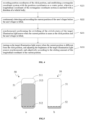
- the brightness sliding bar 50 is composed of a sliding frame 51 and a sliding block 52. Specifically, as shown in part a of FIG. 5 , a top portion 511 of the sliding frame 51 is corresponding to the maximum brightness Lux-max calibrated by the target illumination light source. A bottom portion of the sliding frame 51 is provided with a critical point 512 of the lowest brightness Lux-min calibrated by the target illumination light source and the off state of the target illumination light source. A top portion 513 of a position covered by the sliding block 52 is corresponding to the current brightness Lux-now of the target illumination light source.
- the brightness sliding bar can be configured and displayed on the touchable brightness adjusting interface after the illumination light source is turned on to indicate a current brightness value of the illumination light source (a memory brightness value when it was turned off last time).
- the brightness sliding bar can be configured and displayed on the touchable brightness adjusting interface after the user's finger clicks and slides to indicate the current brightness value.
- the current brightness value of the illumination light source reaches the critical point downward (accordingly, the brightness sliding bar 50 is displayed below the critical point 512 of the sliding frame 51 on a top of the sliding block 52, as shown in part b of FIG. 5 ), the illumination light source is turned off.
- the brightness sliding bar is only used to indicate the current brightness value of the target illumination light source, so as to give the user an intuitive brightness indication.
- the user's adjusting of the target illumination light source does not need to be carried out for the brightness sliding bar, that is, the user does not need to select and slide the sliding block to adjust the target illumination light source (to prevent a problem of poor user experience due to the fact that the sliding block is usually set to be small, the user needs to carefully select and slide, and cannot perform the intuitive blind operation), which is convenient to realize the intuitive blind operation.
- the brightness sliding bar can also be used in other forms to indicate the current brightness value of the target illumination light source.
- the target illumination light source is configured to have a memory brightness value according to the sliding amount of the longitudinal coordinate of the current position.
- the memory brightness value is used to be assigned to the target illumination light source when the target illumination light source is turned off and then turned on again, so that the target illumination light source can perform brightness display with the memory brightness value. That is, the memory brightness value of the target illumination light source before turning off last time is used as an initial brightness value of this lighting, and the memory brightness value is reconfigured to be a final brightness value after this lighting when all sliding operations are finished after this lighting. It should be noted that if the sliding operations after this lighting cause the target illumination light source to be turned off directly, the memory brightness value will not be reconfigured.
- each illumination light source can have a unique memory brightness value (i.e., brightness preference). It can be understood that the sliding operations triggered in the total control hot area of the lamp group adjusting hot area will overwrite the brightness preference of all its associated illumination light sources.
- the step S22 further includes: configuring a buffer area based on the click position, and determining the current position to be different from the click position if the current position is detected to exceed the buffer area for a first time before the user's finger is lifted, that is to say, the user's finger slides.
- shape and size of the buffer area can be dynamically configured or adjusted, and a radius of the buffer area can be greater than or equal to 0, which is less than a set value of a preset threshold.
- the radius of the buffer area is 0, control becomes effective when the user's finger slides after clicking down, and the current brightness of the target illumination light source can be infinitely adjusted when the user's finger slides slightly.
- FIG. 6 is a schematic diagram of the detection of a finger position provided in the embodiments of the present application.
- the processor will record position coordinates A (x0, Y0) where the user clicks, and a rectangular coordinate system will be established with the position coordinates as a center point.
- a longitudinal coordinate (Y coordinate axis) of the rectangular coordinate system is matched with a direction of a vehicle body.
- a function or lattice with A (x0, y0) as a center and composed of XY coordinates can be drawn to describe and delimit a target buffer area. For example, in FIG.
- the processor will continuously detect the current position of the user's finger and record the position coordinates B (x1, y1). The processor will continuously determine whether B (x1, y1) exceeds the target buffer area 60 before the user's finger is lifted.
- B (x1, y1) does not exceed the target buffer area 60, only the switching of the switch states of the illumination light source which corresponds to the target lamp group adjusting hot area corresponding to the click position is controlled after the finger is lifted, and its brightness value is not controlled/adjusted (that is, in this state, the user will perform the on or off operation of the corresponding illumination light source only after the finger is lifted).
- the processor can also map the sliding amount of the user's finger along the Y axis onto the brightness sliding bar in real time.
- the buffer area can be configured only in the total control hot area, or the buffer area can also be configured in the total control hot area and at least some of the sub-control hot areas.
- some models can be without zonal switches or brightness control. If some vehicle models restrict zonal brightness adjusting, the sub-control hot area only responds to a switching operation of the switch states, and does not respond to a brightness adjusting operation of sliding adjusting.
- the total control hot area includes an interactive light spot.
- the interactive light point When states of all illumination light sources controlled by the total control hot area are off, the interactive light point is configured to present a first state.
- the states of all illumination light sources controlled by the total control hot area are on, the interactive light point is configured to present a second state.
- the first state can be represented by an unfilled closed shape (such as a circle) in the total control hot area shown in FIG. 3 .
- the second state is represented by a filled closed shape (such as a circle). In the second state, if a click operation is detected in the total control hot area, all associated illumination light sources will be turned off.
- the first state if the click operation is detected in the total control hot area, all associated illumination light sources are lit up with their memory brightness values.
- the second state if the click operation is detected in the total control hot area, all associated illumination light sources are turned off and the brightness values before turning off are memorized as the memory brightness values. That is, for the click operation triggered in the total control hot area, the switching of the switch states of all its associated illumination light sources is controlled.
- the brightness value formed by the sliding operation for each sub-control hot area is memorized and used as the memory brightness value during the click operation triggered in the total control hot area for turning off all its associated illumination light sources.
- the corresponding illumination light source is lit up with its memory brightness value.
- the brightness of all its associated illumination light sources is updated to the adjusted brightness value (that is, the brightness preference of all its associated illumination light sources is overwritten).
- the first state if the click operation is detected in the total control hot area, all associated illumination light sources can be lit up with a unified set value.
- the second state if the click operation is detected in the total control hot area, all associated illumination light sources are directly turned off and their brightness values are reset/initialized to the set values.
- the brightness adjusting system for multi illumination light sources provided in the embodiments of the present application can realize zonal independent illumination in the plurality of areas in the interior of the vehicle. Independent control of the switches and adjustment of brightness respectively of illumination light sources in each area can be realized by the zonal independent illumination; and the touchable brightness adjusting interface is simple, the touch operation is intuitive, simple, and efficient that intuitive blind operation can be realized. Compared with list switches and complex sliding bars on the traditional interface, the brightness adjusting method provided in the present application is more in line with user's behaviors, and the touchable brightness adjusting interface is more concise and understandable. Moreover, the present application can support the switching of the switch states and the brightness adjusting of the multiple illumination light sources at the same time.
- the application fields of the brightness adjusting method for multi illumination light sources include, but not limited to, brightness adjusting for multi illumination light sources in scenes such as cars, SUVs, trucks, coaches, and aircraft cockpits.
- the present application can be quickly deployed in various areas such as vehicles' central control screens, armrests, seat sides, portable touchable mobile devices and the like.
- each illumination light source can have a unique memory brightness value and can be rewritten.
- some vehicles may have more or less zonal independent illumination areas, and the touchable brightness adjusting interface can also be equipped with more or less lamp group adjusting hot areas.
- the actual vehicle configuration it can be configured that the current brightness can be infinitely adjusted by sliding slightly of the user's finger.
- the buffer area can also be configured to infinitely adjust the current brightness, after the user's finger slides out of the buffer area, and the shape and size of the buffer area can be dynamically configured or adjusted. According to the actual vehicle configuration, some vehicle models can be set that only the total control hot area supports brightness adjusting by sliding, and other sub-control hot areas only respond to the switching operation of the switch states of the illumination light source.
- a brightness adjusting system for multiple illumination light sources is also provided in the present application. Since the brightness adjusting system can implement the brightness adjusting method of multiple illumination light sources provided in the embodiments of the present application, and the principle of the brightness adjusting system to solve the problem is similar to that of the brightness adjusting method, the embodiments of the brightness adjusting system can refer to the implementations of the above-mentioned brightness adjusting method, and repetition will not be repeated.
- the brightness adjusting system 70 for multi illumination light sources includes: a touchable brightness adjusting interface 71, a plurality of lamp group adjusting hot areas 72 (as shown in the figure, the sub-control hot areas A ⁇ F and the total control hot area T), a detecting module 73, and an adjusting module 74.
- the detecting module 73 and the adjusting module 74 are shown in a virtual frame outside the touchable brightness adjusting interface 71, which is used to illustrate that the detecting module 73 and the adjusting module 74 are configured on a lower surface of the touchable brightness adjusting interface 71 opposite to a user facing side, and are not visible relative to the touchable brightness adjusting interface 71.
- the detecting module 73 and the adjusting module 74 can be implemented by processors with detection, calculation, and control functions.
- the plurality of lamp group adjusting hot areas 72 are constructed on the touchable brightness adjusting interface 71, which are used for brightness adjusting triggering.
- the plurality of lamp group adjusting hot areas 72 include a plurality of sub-control hot areas and a total control hot area. Each of the sub-control hot areas is used to adjust at least one of the multi illumination light sources, and the total control hot area is used to adjust all illumination light sources.
- the detecting module 73 is used for recording a click position of a user's finger clicking on the touchable brightness adjusting interface, obtaining a target lamp group adjusting hot area where the click position is located, and continuously detecting and recording a current position of the user's finger before the user's finger is lifted.
- the adjusting module 74 is used for performing switching of switch states and brightness adjusting of a target illumination light source corresponding to the target lamp group adjusting hot area according to the current position.
- the lamp group adjusting hot area is established based on a down-scaled top view of an interior layout of the vehicle.
- a controllable area of each sub-control hot area is adapted to a target illumination area of a corresponding illumination light source, for example, shapes are similar and sizes are proportional. So that touch of the sub-control hot area can truly reflect a target illumination light source that the user wants to manipulate.
- the sub-control hot area is used to control switch states of the corresponding illumination light source and adjust a corresponding brightness value.
- the total control hot area is used to unifiedly control switch states of all illumination light sources and unifiedly adjust a corresponding brightness value.
- the touchable brightness adjusting interface can be a touch display screen in a car or a touch display screen of a mobile device, or other interfaces that can provide touch operation.
- the touchable brightness adjusting interface is deployed in various areas such as vehicles' central control screens, armrests, seat sides, portable touch mobile devices and the like.
- the adjusting module 74 when the detection module 73 detects that the current position is same as the click position and the user's finger is lifted, the adjusting module 74 only performs the switching of the switch states of the target illumination light source. When the detection module 73 detects that the current position is different from the click position, the adjusting module 74 turns on the target illumination light source and synchronously adjusts brightness of the target illumination light source according to the sliding amount of the current position relative to the click position. Because a controllable area range of each lamp group adjusting hot area is established based on the down-scaled top view of the interior layout of the vehicle, the detecting module 73 configured under the touchable brightness adjusting interface is used to detect and calculate the click position, and detect and calculate the current position before the user's finger is lifted.
- the detecting module 73 When the user initiates an interactive operation, the detecting module 73 will record the click position, calculate and determine the illumination light source that the user wants to adjust. If the user's finger does not slide before lifting (the current position is same as the click position), the switch states of the illumination light source which corresponds to the target lamp group adjusting hot area corresponding to the click position are controlled to switch by the adjusting module 74 after the user's finger is lifted, and its brightness value is not controlled/adjusted (that is, in this state, an on or off operation of the corresponding illumination light source will be performed only after the user's finger is lifted).
- the adjusting module 74 will adjust the corresponding brightness of a real-time illumination light source according to the sliding amount of the user's finger in real time (that is, in this state, if the user's finger is not lifted, the on or off operation of the corresponding illumination light source can also be triggered. Even if the user's finger returns to the click position, the brightness of the illumination light source will be adjusted and controlled continuously).
- the brightness adjustment for the target illumination light source can also be reflected in the target lamp group adjusting hot area corresponding to the touchable brightness adjusting interface in real time. For example, when the user clicks one lamp group adjusting hot area to turn on the target illumination light source, the lamp group adjusting hot area and the target illumination light source are lit up to a preset brightness value at the same time. When the user clicks one lamp group adjusting hot area and slides his finger to turn on and adjust the brightness of the target illumination light source, the lamp group adjusting hot area and the target illumination light source are lit up, and the brightness of the lamp group adjusting hot area and the brightness of the target illumination light source change in accordance with the sliding amount of a longitudinal coordinate of the current position, so as to improve intuitive and friendly handling.
- a light-emitting circuit controlled by a controller which is configured under the touchable brightness adjusting interface, is used to perform lighting/resting screen of the target lamp group adjusting hot area, and display current brightness in real time.
- the sliding amount of the longitudinal ordinate of the current position is mapped to a brightness sliding bar in real time.
- the brightness sliding bar is displayed on the touchable brightness adjusting interface to provide users with an intuitive indication of the brightness value of the real-time illumination light source.
- the brightness sliding bar can be displayed on the target lamp group adjusting hot area, and can also be displayed on other areas of the touchable brightness adjusting interface. With sliding of the user's finger, a position of a sliding block of the brightness sliding bar changes in real time, and display brightness corresponding to the target lamp group adjusting hot area on the touchable brightness adjusting interface and the brightness corresponding to the real-time illumination light source also change in real time.
- a composition diagram of the brightness sliding bar is shown in FIG. 5 .
- the target illumination light source is configured to have a memory brightness value according to the sliding amount of the longitudinal coordinate of the current position.
- the memory brightness value is used to be assigned to the target illumination light source when the target illumination light source is turned off and then turned on again, so that the target illumination light source can perform brightness display with the memory brightness value. That is, the memory brightness value of the target illumination light source before turning off last time is used as an initial brightness value of this lighting, and the memory brightness value is reconfigured to be a final brightness value after this lighting when all sliding operations are finished after this lighting. It should be noted that if the sliding operations after this lighting cause the target illumination light source to be turned off directly, the memory brightness value will not be reconfigured.
- each illumination light source can have a unique memory brightness value (i.e., brightness preference). It can be understood that the sliding operations triggered in the total control hot area of the lamp group adjusting hot area will overwrite the brightness preference of all its associated illumination light sources.
- a buffer area is configured based on the click position. If the current position is detected to exceed the buffer area for a first time before the user's finger is lifted, the current position is determined to be different from the click position. That is to say, the user's finger slides.
- shape and size of the buffer area can be dynamically configured or adjusted, and a radius of the buffer area can be greater than or equal to 0, which is less than a set value of a preset threshold. When the radius of the buffer area is 0, control becomes effective when the user's finger slides after clicking down, and the current brightness of the target illumination light source can be infinitely adjusted when the user's finger slides slightly.
- the buffer area can be configured only in the total control hot area, or the buffer area can also be configured in the total control hot area and at least some of the sub-control hot areas.
- some models can be without zonal switches or brightness control. If some vehicle models restrict zonal brightness adjusting, the sub-control hot area only responds to a switching operation of the switch states, and does not respond to a brightness adjusting operation of sliding adjusting.
- the total control hot area includes an interactive light spot.
- the interactive light point When states of all illumination light sources controlled by the total control hot area are off, the interactive light point is configured to present a first state.
- the states of all illumination light sources controlled by the total control hot area are on, the interactive light point is configured to present a second state.
- the first state can be represented by an unfilled closed shape (such as a circle) in the total control hot area shown in FIG. 3 .
- the second state is represented by a filled closed shape (such as a circle). In the second state, if a click operation is detected in the total control hot area, all associated illumination light sources will be turned off.
- the first state if the click operation is detected in the total control hot area, all associated illumination light sources are lit up with their memory brightness values.
- the second state if the click operation is detected in the total control hot area, all associated illumination light sources are turned off and the brightness value before turning off is memorized as the memory brightness value. That is, for the click operation triggered in the total control hot area, the switching of the switch states of all its associated illumination light sources is controlled.
- the brightness value formed by the sliding operation for each sub-control hot area is memorized and used as the memory brightness value during the click operation triggered in the total control hot area for turning off all its associated illumination light sources.
- the corresponding illumination light source is lit up with its memory brightness value.
- the brightness of all its associated illumination light sources is updated to the adjusted brightness value (that is, the brightness preference of all its associated illumination light sources is overwritten).
- the first state if a click operation is detected in the total control hot area, all associated illumination light sources can be lit up with a unified set value.
- the second state if the click operation is detected in the total control hot area, all associated illumination light sources are directly turned off and their brightness values are reset/initialized to the set values.
- the brightness adjusting system for multi illumination light sources provided in the embodiments of the present application can realize zonal independent illumination in the plurality of areas in the interior of the vehicle. Independent control of the switches and adjustment of brightness respectively of the illumination light sources in each area could be realized by the zonal independent illumination; and the touchable brightness adjusting interface is simple, the touch operation is intuitive, simple, and efficient that intuitive blind operation can be realized. Compared with list switches and complex sliding bars on a traditional interface, the brightness adjusting method provided in the present application is more in line with user's behaviors, and the touchable brightness adjusting interface is more concise and understandable. Moreover, the present application can support the switching of the switch states and the brightness adjusting of multiple illumination light sources at the same time.
- the application fields of the brightness adjusting method for multi illumination light sources include, but not limited to, the brightness adjusting for multi illumination light sources in scenes such as cars, SUVs, trucks, coaches, and aircraft cockpits.
- the present application can be quickly deployed in various areas such as vehicles' central control screens, armrests, seat sides, portable touchable mobile devices and the like.
- each illumination light source can have a unique memory brightness value and can be rewritten.
- some vehicles may have more or less zonal independent illumination areas, and the touchable brightness adjusting interface can also be equipped with more or less lamp group adjusting hot areas.
- the actual vehicle configuration it can be configured that the current brightness can be infinitely adjusted by sliding slightly of the user's finger.
- the buffer area can also be configured to infinitely adjust the current brightness, after the user's finger slides out of the buffer area, and the shape and size of the buffer area can be dynamically configured or adjusted. According to the actual vehicle configuration, some vehicle models can be set that only the total control hot area supports brightness adjusting by sliding, and other sub-control hot areas only respond to the switching operation of the switch states of the illumination light source.
- the program can be stored in a computer-readable storage medium, which is referred to here as a storage medium, such as read only memory (ROM)/random access memory (RAM), magnetic disc, optical disc, etc. That is, a computer-readable storage medium is further disclosed in the present application.
- the computer-readable storage medium stores a computer executable program. When the computer executable program is executed, the brightness adjusting method described in the above embodiments of the present application is realized.
- the computer executable program can be stored in RAM, memory, ROM, electrically programmable ROM, electrically erasable programmable ROM, register, hard disk, removable disk, CD-ROM, or any other form of storage medium known in the technical field.
Landscapes
- Engineering & Computer Science (AREA)
- Theoretical Computer Science (AREA)
- General Engineering & Computer Science (AREA)
- Human Computer Interaction (AREA)
- Physics & Mathematics (AREA)
- General Physics & Mathematics (AREA)
- Software Systems (AREA)
- Mechanical Engineering (AREA)
- Arrangements Of Lighting Devices For Vehicle Interiors, Mounting And Supporting Thereof, Circuits Therefore (AREA)
Applications Claiming Priority (1)
| Application Number | Priority Date | Filing Date | Title |
|---|---|---|---|
| CN202110921655.2A CN113377267B (zh) | 2021-08-12 | 2021-08-12 | 一种多照明光源的亮度调控方法及装置、存储介质 |
Publications (1)
| Publication Number | Publication Date |
|---|---|
| EP4134277A1 true EP4134277A1 (fr) | 2023-02-15 |
Family
ID=77576798
Family Applications (1)
| Application Number | Title | Priority Date | Filing Date |
|---|---|---|---|
| EP22189992.5A Withdrawn EP4134277A1 (fr) | 2021-08-12 | 2022-08-11 | Procédé de réglage de la luminosité, appareil, et support de stockage de multiples sources de lumière d'éclairage |
Country Status (2)
| Country | Link |
|---|---|
| EP (1) | EP4134277A1 (fr) |
| CN (1) | CN113377267B (fr) |
Cited By (6)
| Publication number | Priority date | Publication date | Assignee | Title |
|---|---|---|---|---|
| WO2024134324A1 (fr) * | 2022-12-23 | 2024-06-27 | Agco International Gmbh | Commande basée sur des gestes pour commander des lumières d'un véhicule |
| WO2024134325A1 (fr) * | 2022-12-23 | 2024-06-27 | Agco International Gmbh | Commande gestuelle pour commander des lumières d'un véhicule |
| FR3150160A1 (fr) * | 2023-06-22 | 2024-12-27 | Psa Automobiles Sa | Procédé et dispositif de contrôle d’intensité lumineuse d’éléments lumineux présents au niveau d’une planche de bord d’un véhicule. |
| CN119536005A (zh) * | 2024-11-29 | 2025-02-28 | 江西晶华微电子有限公司 | 一种基于触控显示屏的智能家居控制系统 |
| CN120053898A (zh) * | 2025-04-27 | 2025-05-30 | 深圳亿上光科技有限公司 | 理疗控制电路、方法、存储介质、程序产品及理疗设备 |
| CN120434861A (zh) * | 2025-07-08 | 2025-08-05 | 启福光科技(南京)有限公司 | 停车场智能照明控制系统 |
Families Citing this family (5)
| Publication number | Priority date | Publication date | Assignee | Title |
|---|---|---|---|---|
| CN114007309B (zh) * | 2021-10-22 | 2023-06-16 | 珠海格力电器股份有限公司 | 灯光管理方法、装置、电子装置及可读存储介质 |
| CN114030355A (zh) * | 2021-11-15 | 2022-02-11 | 智己汽车科技有限公司 | 一种车辆控制方法、装置、车辆及介质 |
| CN114677989B (zh) * | 2022-03-29 | 2023-12-12 | 智己汽车科技有限公司 | 一种屏幕亮度调节方法及设备 |
| CN115223517B (zh) * | 2022-06-28 | 2024-05-17 | 智己汽车科技有限公司 | 基于多屏幕亮度调节的控制方法及控制装置 |
| CN115107748A (zh) * | 2022-07-15 | 2022-09-27 | 浙江吉利控股集团有限公司 | 一种泊车方法和装置 |
Citations (3)
| Publication number | Priority date | Publication date | Assignee | Title |
|---|---|---|---|---|
| DE102012010044A1 (de) * | 2012-05-23 | 2013-11-28 | Volkswagen Aktiengesellschaft | Vorrichtung zur Steuerung einer Beleuchtung in einem Fahrzeuginnenraum |
| US20170166056A1 (en) * | 2015-12-11 | 2017-06-15 | Ford Global Technologies, Llc | In-vehicle component control user interface |
| US20190021156A1 (en) * | 2016-06-01 | 2019-01-17 | XKGlow, Inc | Lighting Control System |
Family Cites Families (7)
| Publication number | Priority date | Publication date | Assignee | Title |
|---|---|---|---|---|
| CN102490651B (zh) * | 2011-12-07 | 2015-07-15 | 上海科世达-华阳汽车电器有限公司 | 机动车及其车载内顶灯模块 |
| CN202652661U (zh) * | 2012-07-20 | 2013-01-02 | 深圳市和玛科技有限公司 | 一种灯光集中控制系统 |
| JP2016055838A (ja) * | 2014-09-12 | 2016-04-21 | 矢崎総業株式会社 | 車内照明装置 |
| CN204559954U (zh) * | 2015-03-31 | 2015-08-12 | 深圳市万朗光电有限公司 | 汽车室内灯 |
| CN104837281B (zh) * | 2015-05-27 | 2018-07-10 | 常州市武进区半导体照明应用技术研究院 | 照明控制系统、方法及装置 |
| CN205871863U (zh) * | 2016-08-09 | 2017-01-11 | 黄山市瑞兴汽车电子有限公司 | 采用触摸屏控制的智能型汽车顶灯控制电路 |
| CN213892330U (zh) * | 2020-12-09 | 2021-08-06 | 广州新晨汽车零部件有限公司 | 一种用于汽车氛围灯的触控装置 |
-
2021
- 2021-08-12 CN CN202110921655.2A patent/CN113377267B/zh not_active Expired - Fee Related
-
2022
- 2022-08-11 EP EP22189992.5A patent/EP4134277A1/fr not_active Withdrawn
Patent Citations (3)
| Publication number | Priority date | Publication date | Assignee | Title |
|---|---|---|---|---|
| DE102012010044A1 (de) * | 2012-05-23 | 2013-11-28 | Volkswagen Aktiengesellschaft | Vorrichtung zur Steuerung einer Beleuchtung in einem Fahrzeuginnenraum |
| US20170166056A1 (en) * | 2015-12-11 | 2017-06-15 | Ford Global Technologies, Llc | In-vehicle component control user interface |
| US20190021156A1 (en) * | 2016-06-01 | 2019-01-17 | XKGlow, Inc | Lighting Control System |
Cited By (7)
| Publication number | Priority date | Publication date | Assignee | Title |
|---|---|---|---|---|
| WO2024134324A1 (fr) * | 2022-12-23 | 2024-06-27 | Agco International Gmbh | Commande basée sur des gestes pour commander des lumières d'un véhicule |
| WO2024134325A1 (fr) * | 2022-12-23 | 2024-06-27 | Agco International Gmbh | Commande gestuelle pour commander des lumières d'un véhicule |
| EP4701342A3 (fr) * | 2022-12-23 | 2026-04-08 | AGCO International GmbH | Commande basée sur des gestes pour commander des lumières d'un véhicule |
| FR3150160A1 (fr) * | 2023-06-22 | 2024-12-27 | Psa Automobiles Sa | Procédé et dispositif de contrôle d’intensité lumineuse d’éléments lumineux présents au niveau d’une planche de bord d’un véhicule. |
| CN119536005A (zh) * | 2024-11-29 | 2025-02-28 | 江西晶华微电子有限公司 | 一种基于触控显示屏的智能家居控制系统 |
| CN120053898A (zh) * | 2025-04-27 | 2025-05-30 | 深圳亿上光科技有限公司 | 理疗控制电路、方法、存储介质、程序产品及理疗设备 |
| CN120434861A (zh) * | 2025-07-08 | 2025-08-05 | 启福光科技(南京)有限公司 | 停车场智能照明控制系统 |
Also Published As
| Publication number | Publication date |
|---|---|
| CN113377267A (zh) | 2021-09-10 |
| CN113377267B (zh) | 2021-10-29 |
Similar Documents
| Publication | Publication Date | Title |
|---|---|---|
| CN113377267B (zh) | 一种多照明光源的亮度调控方法及装置、存储介质 | |
| US20220274589A1 (en) | Automated Parking Interaction Method and Apparatus | |
| US11182072B2 (en) | Touch screen, a vehicle having the same, and a method of controlling the vehicle | |
| JP2011081798A (ja) | ユーザ構成可能な車両ユーザインターフェース | |
| US12093590B2 (en) | Content display control apparatus and content display control method | |
| US12015399B2 (en) | Switch device with integrated touch sensor | |
| EP2797767A1 (fr) | Systèmes et procédés pour des images d'affichage améliorées | |
| US20210019042A1 (en) | Vehicle and Controlling Method of the Same | |
| KR20190010107A (ko) | 스티어링 휠, 이를 포함하는 차량, 및 차량의 제어방법 | |
| KR102326766B1 (ko) | 디스플레이 장치의 선택된 키 표시 방법 및 디스플레이 장치 | |
| CN115826802A (zh) | 车载服务显示方法、车辆及程序产品 | |
| CN107757463B (zh) | 控制车辆前照灯的车辆及方法 | |
| CN115848138A (zh) | 座舱视角切换方法、装置、设备及车辆 | |
| CN113928195B (zh) | 一种车辆控制方法和系统 | |
| JP7780701B2 (ja) | 車両のインストルメントパネルの別個のディスプレイデバイスでのコンテンツの提示 | |
| CN111506229A (zh) | 一种交互方法、装置和车辆 | |
| CN113400936A (zh) | 一种中控屏幕的显示控制方法、装置及汽车 | |
| CN115195585A (zh) | 一种汽车化妆镜灯控制方法、装置、设备及存储介质 | |
| CN212966138U (zh) | 一种车载信息输入系统及车辆 | |
| CN116572860B (zh) | 车辆设备的控制方法、装置、车辆和存储介质 | |
| CN115097929B (zh) | 车载投屏方法、装置、电子设备、存储介质和程序产品 | |
| CN115223517B (zh) | 基于多屏幕亮度调节的控制方法及控制装置 | |
| KR20160140033A (ko) | 차량용 투명 디스플레이 장치 | |
| CN112885305A (zh) | 车辆背光调节方法、装置以及系统 | |
| CN116403544A (zh) | 车辆屏幕的显示控制方法、装置、电子设备及存储介质 |
Legal Events
| Date | Code | Title | Description |
|---|---|---|---|
| PUAI | Public reference made under article 153(3) epc to a published international application that has entered the european phase |
Free format text: ORIGINAL CODE: 0009012 |
|
| STAA | Information on the status of an ep patent application or granted ep patent |
Free format text: STATUS: REQUEST FOR EXAMINATION WAS MADE |
|
| STAA | Information on the status of an ep patent application or granted ep patent |
Free format text: STATUS: THE APPLICATION HAS BEEN WITHDRAWN |
|
| 17P | Request for examination filed |
Effective date: 20220811 |
|
| AK | Designated contracting states |
Kind code of ref document: A1 Designated state(s): AL AT BE BG CH CY CZ DE DK EE ES FI FR GB GR HR HU IE IS IT LI LT LU LV MC MK MT NL NO PL PT RO RS SE SI SK SM TR |
|
| 18W | Application withdrawn |
Effective date: 20230207 |