EP4134294A1 - Système de direction pour un véhicule agricole - Google Patents
Système de direction pour un véhicule agricole Download PDFInfo
- Publication number
- EP4134294A1 EP4134294A1 EP22168283.4A EP22168283A EP4134294A1 EP 4134294 A1 EP4134294 A1 EP 4134294A1 EP 22168283 A EP22168283 A EP 22168283A EP 4134294 A1 EP4134294 A1 EP 4134294A1
- Authority
- EP
- European Patent Office
- Prior art keywords
- steering
- valve
- control
- switching
- unit
- Prior art date
- Legal status (The legal status is an assumption and is not a legal conclusion. Google has not performed a legal analysis and makes no representation as to the accuracy of the status listed.)
- Granted
Links
Images
Classifications
-
- B—PERFORMING OPERATIONS; TRANSPORTING
- B62—LAND VEHICLES FOR TRAVELLING OTHERWISE THAN ON RAILS
- B62D—MOTOR VEHICLES; TRAILERS
- B62D5/00—Power-assisted or power-driven steering
- B62D5/001—Mechanical components or aspects of steer-by-wire systems, not otherwise provided for in this maingroup
-
- B—PERFORMING OPERATIONS; TRANSPORTING
- B62—LAND VEHICLES FOR TRAVELLING OTHERWISE THAN ON RAILS
- B62D—MOTOR VEHICLES; TRAILERS
- B62D5/00—Power-assisted or power-driven steering
- B62D5/001—Mechanical components or aspects of steer-by-wire systems, not otherwise provided for in this maingroup
- B62D5/005—Mechanical components or aspects of steer-by-wire systems, not otherwise provided for in this maingroup means for generating torque on steering wheel or input member, e.g. feedback
-
- B—PERFORMING OPERATIONS; TRANSPORTING
- B62—LAND VEHICLES FOR TRAVELLING OTHERWISE THAN ON RAILS
- B62D—MOTOR VEHICLES; TRAILERS
- B62D5/00—Power-assisted or power-driven steering
- B62D5/06—Power-assisted or power-driven steering fluid, i.e. using a pressurised fluid for most or all the force required for steering a vehicle
- B62D5/09—Power-assisted or power-driven steering fluid, i.e. using a pressurised fluid for most or all the force required for steering a vehicle characterised by means for actuating valves
- B62D5/091—Hydraulic steer-by-wire systems, e.g. the valve being actuated by an electric motor
-
- B—PERFORMING OPERATIONS; TRANSPORTING
- B62—LAND VEHICLES FOR TRAVELLING OTHERWISE THAN ON RAILS
- B62D—MOTOR VEHICLES; TRAILERS
- B62D5/00—Power-assisted or power-driven steering
- B62D5/06—Power-assisted or power-driven steering fluid, i.e. using a pressurised fluid for most or all the force required for steering a vehicle
- B62D5/09—Power-assisted or power-driven steering fluid, i.e. using a pressurised fluid for most or all the force required for steering a vehicle characterised by means for actuating valves
- B62D5/093—Telemotor driven by steering wheel movement
Definitions
- the present invention relates to a steering system for an agricultural vehicle according to the preamble of claim 1.
- a steering system for an agricultural vehicle of the type mentioned is known.
- the vehicle has at least one primary-controlled axle and at least one other axle, each of which is assigned at least one steering cylinder for changing a wheel lock angle.
- the pairs of wheels arranged on the axles are assigned the double-acting steering cylinder for actuating the wheels, with the steering cylinder being acted upon by a fluid supplied by a valve unit, which fluid is supplied to the valve unit by means of a hydraulic pump.
- the valve unit consists of an electro-hydraulic steering control and switching unit and a hydraulic steering control and switching unit, which has a hydraulic device connected to a steering wheel of the vehicle, a so-called orbitrol.
- Each of the steering control and switching units has switching valves.
- the switching valves of the respective switching units are controlled individually in order to enable different types of steering when controlling the axles.
- One type of steering provides for the activation of only the primarily controlled axle
- another type of steering provides for all-wheel steering.
- a steering cylinder is controlled by the first and the second steering control unit and the associated switching units.
- a steering wheel counter-torque is generated on a steering wheel that is operatively connected to the hydraulic device, which counter-torque corresponds to that when the steering cylinder is actuated by actuating the hydraulic device.
- the steering wheel which is connected to an electric rotary encoder, is used as a steering angle set value generator, with the driver of the vehicle experiencing the same steering feel.
- the steering wheel can continue to be turned, even if a double-acting piston in the steering cylinder has reached its maximum position has reached, which corresponds to a steering stop.
- the driver therefore does not receive any feedback from the steering system, informing him that the maximum steering stop has been reached.
- the driver does not receive any force feedback from the steering in the form that he is used to with hydraulic steering by means of the hydraulic device or the orbitrol.
- the object of the invention is to further develop a steering system for an agricultural vehicle of the type mentioned above, which is characterized by an adjustable operating behavior of a steering wheel.
- the at least one control device is set up to control the at least three switching valves simultaneously in the first steering mode by means of a single, in particular electrical, signal in order to set at least one actuation behavior of the steering wheel.
- the at least one control device generates a single electrical signal, which is used to simultaneously control the at least three switching valves.
- the invention is based on the idea that in the first steering mode, also referred to below as the fully electronic steering mode, in which the steering movement of the steering wheel connected to the second steering control and switching unit is detected by sensors and transmitted as a target steering angle signal to the first steering control and switching unit, the driver of the vehicle is given the opportunity in a simple way to adjust at least one actuation behavior of the steering wheel.
- actuation behavior of the steering wheel describes the behavior resulting from the actuation of the steering wheel to set a steering angle, which is characterized by the absence or presence of a haptic perception by the driver.
- outputs of the hydraulic device or the orbitrol are connected to one another, so that when the steering wheel is turned, the orbitrol conveys its volume flow directly in the direction of the tank.
- the agricultural vehicle is in particular a tractor.
- the tractor has two steerable axles.
- the at least one control device can be designed with a memory unit in which characteristic curves for controlling the first steering control and switching unit are stored, and with a computing unit for processing the characteristic curves.
- the second steering control and switching unit can include an electrically controlled actuating valve which, when controlled by the singular electrical signal, provides the at least one control device with a switching pressure which acts on the three switching valves simultaneously.
- the actuating valve can provide a switching pressure which simultaneously changes the switching position of the three switching valves.
- the loading of the three switching valves with the switching pressure of the actuating valve can lead to the interruption of the hydraulic connection between the second steering control and switching unit and the steering cylinders.
- the fully electronic steering mode sets in, with the turning of the steering wheel also being able to be moved or turned beyond the reaching of an end stop of the steering cylinder as an actuation behavior of the steering wheel.
- Two of the switching valves of the second steering control and switching unit can preferably be designed as normally open valves (NO valves) and one of the switching valves can be designed as a normally closed valve (NC valve).
- NO valves normally open valves
- NC valve normally closed valve
- the two switching valves designed as NO valves are in the open switching position when there is no switching pressure applied.
- the switching valve, which is designed as an NC valve is in the closed switching position when it is not subjected to a switching pressure.
- the switching valve designed as an NC valve can be arranged between hydraulic lines which connect the hydraulic device to the steering cylinders through the respective switching valve designed as an NO valve.
- the switching valve designed as an NC valve By switching the switching valve designed as an NC valve, the outputs of the Orbitrol can be connected to each other, i.e. short-circuited.
- the two switching valves designed as NO valves are moved into their closed switching position by the application of a control pressure, while the switching valve designed as an NC valve is moved into its open switching position.
- the hydraulic connection between the hydraulic device and the orbitrol and the steering cylinders is interrupted.
- this establishes a hydraulic connection between the outlets of the Orbitrol, so that the Orbitrol returns its volume flow directly in the direction of the tank when the steering wheel is turned.
- the steering wheel is operated in such a way that the driver can turn the steering wheel endlessly.
- an electrically controlled throttle valve can be connected upstream of the switching valve designed as an NC valve. Additional actuation behavior of the steering wheel can be adjusted by activating the electrically activated throttle valve. The control takes place depending on the actuation of the steering wheel in order to set a steering angle.
- the throttle valve can be set up to throttle the volume flow between the hydraulic device and a tank proportional to the current flow down to a minimum flow rate.
- the electrically controlled throttle valve is used to allow the volume flow derived from the Orbitrol directly into the tank in the first steering mode or fully electronic steering mode to pass unthrottled in the de-energized state and to throttle it to a minimum flow rate with increasing energization.
- the throttle valve is preferably energized as a function of the steering angle that occurs as a result of the steering movement of the steering wheel. By throttling the short-circuited volume flow, an increase in force on the steering wheel that can be felt by the driver can be achieved, which represents a further actuation behavior of the steering wheel.
- the minimum flow rate is set to a value which, even with maximum current flow, ensures that the driver can turn the steering wheel in order to ensure steerability of the vehicle even if the throttle valve fails.
- the throttle valve can be set up to throttle the volume flow between the hydraulic device and a tank proportional to the current flow until the flow is interrupted.
- the only one throttle valve can be set up both to throttle down to a minimum flow rate with increasing energization and to throttle proportional to the energization until the flow is interrupted.
- the characteristics of the control of the throttle valve ie that only one throttle valve throttles until the minimum flow rate is reached or until the flow is interrupted, can be specified by the at least one control device.
- the hydraulic cylinder or cylinders reaches an end stop, the flow of current through the throttle valve is at its maximum, so that the flow between Orbitrol and the tank is interrupted. With the blocking of the connection between the two exits of the Orbitrol the steering wheel can no longer be turned. In this way, an end stop of the steering wheel, which prevents further turning, can be simulated as a further actuation behavior.
- a pressure switch which switches as a function of a pressure exerted by the actuation of the steering wheel, in order to cancel the interruption in the flow. It can thus be avoided that the steering wheel can no longer be actuated if the throttle valve fails at the moment when the flow is interrupted. In such a situation, the pressure switch may open to override the fully electronic steering mode. To do this, the connection between the outputs of the Orbitrol and the NO valves of the second steering control and switching unit can be restored by releasing the pressure switch.
- the at least one control device can be set up to adjust the energization of the electrically controlled throttle valve as a function of the set steering angle.
- the throttling of the volume flow can increase until the set minimum flow rate is reached or the flow is interrupted.
- the at least one control device can be assigned a control element having a self-holding function for controlling the actuating valve.
- the actuating valve can be actuated electrically, for example by electrical self-locking after actuating an operating element designed as a button or switch.
- an operating element designed as a button or switch.
- the driver can switch to fully electronic steering mode.
- the electrical self-locking can be canceled again by actuating the control element again or by actuating another element, for example a road switch or the selection of another steering program, so that the steering system changes to another steering mode, in particular the orbital steering steering mode, or falls back.
- An actuation behavior of the steering wheel can be a continued actuation of the steering wheel independent of reaching an end stop of the steering cylinder of the primarily controlled axle.
- An actuation behavior of the steering wheel can be the generation of an increasing resistance when actuating the steering wheel.
- An actuation behavior of the steering wheel can simulate reaching an end stop of the steering cylinder.
- the actuating valve and/or the throttle valve can be arranged in a common housing of the first steering control and switching unit and/or the second steering control and switching unit or in a separate housing.
- Arranging the actuating valve and/or the throttle valve in a separate housing has the advantage that the components can be retrofitted or optionally installed in vehicles that use the fully electronic steering mode.
- exactly one control device can be provided for the activation of the first steering control and switching unit, which controls at least the actuating valve in addition to the proportional unit and the blocking unit.
- the precisely one control device can be set up to also carry out the actuation of the second steering control and switching unit.
- two control devices can be provided, of which one control device serves to activate the first steering control and switching unit and the other control device serves to activate the second steering control and switching unit. It can further be provided that one of the two control devices is set up to control at least the actuating valve of the second steering control and switching unit.
- An agricultural vehicle in particular a tractor, has at least two axles, a front axle and a rear axle, with wheels arranged on them.
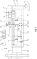
- a steering system 1 is provided for steering the vehicle, as shown in FIG 1 shown.
- the steering system 1 enables multi-axle steering, which is used where different uses of agricultural vehicles make it necessary to adapt the properties of the vehicle in terms of maneuverability and directional stability. These increased requirements can be realized by different types of steering.
- agricultural vehicles In addition to the usual front axle steering, in which only the front wheels are turned while the rear wheels remain in the straight position, agricultural vehicles have a type of steering referred to as all-wheel steering, in which the front and rear wheels are turned in opposite directions. All-wheel steering is preferably used where the vehicle has to be moved in a small space.
- the representation in 1 shows the steering system 1 according to the invention, which comprises at least one primary-controlled axle, here and preferably the front axle, and at least one further axle, here the rear axle, each of which is assigned at least one steering cylinder 2 for changing a wheel lock angle of the agricultural vehicle.
- the steering system 1 comprises a valve unit 4 connected to a supply unit 3 for pressurizing the steering cylinder 2, the valve unit 4 having a first steering control and switching unit 5 with a proportional unit 6 and a blocking unit 7 and a second steering control and switching unit 8 with a hydraulic device 9, hereinafter synonymously referred to as Orbitrol, and at least three switching valves 10, 11, 12 includes.
- the steering system 1 also includes at least one control device 13 and/or 18. At least the control device 13 can be equipped with a memory unit 14, in which characteristic curves for controlling the first steering control and switching unit 5 are stored, and with a computing unit 15 for processing the characteristics stored in memory unit 14 can be implemented.
- the steering cylinders 2 are designed as double-acting hydraulic cylinders.
- the supply unit 3 designed as a hydraulic pump is connected to the first steering control and switching unit 5 and the steering cylinder 2 by a first supply line 16 .
- the supply unit 3 is connected to the second steering control and switching unit 5 and the steering cylinder 2 by a second supply line 17 .
- the vehicle is steered hydraulically by means of the first steering control and switching unit 5 .
- the proportional unit 6 comprises at least one electrically controlled proportional valve and the blocking unit 7 has two electrically controlled switching valves.
- the first steering control and switching unit 5 can be electrically activated by the at least one control device 13 .
- the first steering control and switching unit 5 can include the control device 18 designed as an electronic module for its electrical activation.
- a steering movement 20 generated by a steering wheel 19 arranged in a driver's cab of the vehicle is detected by sensors, for example by a steering wheel sensor 21.
- the control device 13 is set up to evaluate the measurement signals of the steering wheel sensor 21 and, depending on the evaluation, to generate control signals with which the first steering control and switching unit 5 is controlled.
- the first steering control and switching unit 5 can be activated directly by the control device 13 or by the control device 18 designed as an electronic module. Alternatively, the control device 18 can take over this task instead of the control device 13, so that the control device 13 as such could be dispensed with.
- the switching valves 10, 11, 12 are in their in 1 shown switching position.
- the two switching valves 10, 11 are designed as normally open valves (NO valves) and are in the open switching position when there is no switching pressure applied.
- the third switching valve 12 is normally closed valve (NC valve) and is in the closed switching position when there is no switching pressure applied.
- outputs 9a, 9b of the orbitrol 9 are connected to the steering cylinder 2 via hydraulic lines 22, 23.
- the third switching valve 12 is arranged between a hydraulic line 25 which connects the hydraulic lines 22, 23 assigned to the outputs 9a, 9b of the orbitrol 9 to one another.
- the switch position of the switching valves 10, 11, 12 shown the driver of the vehicle experiences haptic feedback when the steering cylinder 2 reaches an end stop. This steering mode is called orbital steering.
- the vehicle is steered by means of the second steering control and switching unit 8.
- the switching valves 10, 11, 12, they change their switching position, with the switching valves 10, 11 separating the orbitrol 9 from the steering cylinder when the pressure is appropriate 2 effect.
- the switching valve 12 establishes a connection between the outlets 9a, 9b of the orbitrol 9 when a control pressure is applied.
- the orbitrol 9 conveys the volumetric flow supplied by the supply unit 3 through the supply line 17 back into a tank T. By "short-circuiting" the orbitrol 9, a driver can turn the steering wheel 19 endlessly, even if the steering cylinder 2 has already reached its end stop.
- the steering system 1 can be operated in a first steering mode and at least one additional steering mode, such as the orbital steering mode, with the control device 13 or the control device 18 being set up to control the steering movement 20 of the steering wheel connected to the second steering control and switching unit 8 in the first steering mode 19 to be detected by sensors and to be transmitted as a desired steering angle signal to the first steering control and switching unit 5 in order to actuate it.
- the first steering mode in which the vehicle is steered by means of the second steering control and switching unit 8, is referred to as fully electronic steering mode.
- the control device 13 or the control device 18 is set up to, in the fully electronic steering mode, by means of a singular, in particular electric, Signal to control the at least three switching valves 10, 11, 12 simultaneously in order to set at least one actuation behavior of the steering wheel 19.
- the second steering control and switching unit 8 comprises an electrically actuated actuating valve 24.
- the electrically actuated actuating valve 24 When actuated by the electrical signal generated by the control device 13 or the control device 18, the electrically actuated actuating valve 24 provides a switching pressure which actuates the three switching valves 10, 11, 12 applied at the same time. This results in an actuation behavior of the steering wheel 19 which is a continued actuation of the steering wheel 19 independently of the reaching of an end stop of the steering cylinder 2 of the primary-controlled axle.
- the actuating valve 24 is connected via a control line 26 to the switching valves 10, 11, 12 in terms of signals. In the switching position shown, the control line 26 is connected to the tank T.
- the actuation by means of the control device 13 or the control device 18 moves the actuating valve 24 into a switching position in which the control line 26 is connected to the supply line 17 .
- the three switching valves 10, 11, 12 are simultaneously subjected to their control pressure in order to change the at least one actuation behavior of the steering wheel 19.
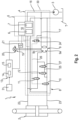
- In 2 1 is a block diagram of the steering system 1 according to FIG 1 shown according to a further embodiment.
- This embodiment makes it possible to adjust an operating behavior of the steering wheel 19, which is causing an increasing resistance when the steering wheel 19 is operated. An increase in force that can be felt by the driver is generated on the steering wheel 19 .
- the second steering control and switching unit 8 additionally includes an electrically controlled throttle valve 27 .
- the electrically controlled throttle valve 27 is connected upstream of the switching valve 12 designed as an NC valve in the hydraulic line 25 .
- the throttle valve 27 is set up to throttle the volume flow between the hydraulic device 9 and the tank T proportional to the current flow down to a minimum flow rate.
- the throttle valve 27 is energized as a function of the steering angle that occurs as a result of the steering movement 20 of the steering wheel 19 .
- the electrically controlled throttle valve 27 is used to allow the volume flow diverted from the Orbitrol 9 directly into the tank T in the first steering mode or fully electronic steering mode to pass unthrottled in the de-energized state and to throttle it to a minimum flow rate with increasing energization.
- the minimum flow rate is set to a value which ensures that the driver can turn the steering wheel 19 even with a maximum current supply, in order to ensure the steerability of the vehicle even if the throttle valve 27 fails.
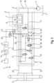
- In 3 1 is a block diagram of the steering system 1 according to FIG 1 shown according to a third embodiment.
- This embodiment makes it possible to set an actuation behavior of the steering wheel 19 which, in addition to causing an increasing resistance when the steering wheel 19 is actuated, as an additional actuation behavior of the steering wheel 19 simulates reaching an end stop of the steering cylinder 2 .
- the second steering control and switching unit 8 includes a likewise electrically controlled throttle valve 28 which is set up to throttle the volumetric flow proportional to the energization until the flow is interrupted.
- the electrically controlled throttle valve 28 is used to allow the volume flow derived from the Orbitrol 9 directly into the tank T in the first steering mode or fully electronic steering mode to pass unthrottled in the de-energized state and to throttle it with increasing energization until the flow is interrupted. In this way, an end stop of the steering wheel 19 can be simulated as a further actuation behavior.
- the throttle valve 28 used instead of the throttle valve 27 can be set up both to throttle to a minimum flow rate with increasing current flow and to throttle proportional to the current flow until the flow is interrupted.
- the characteristics of the activation of the throttle valve 28, ie that only one throttle valve 28 throttles until the minimum flow rate is reached or until the flow is interrupted, can be specified by the control device 13.
- a pressure switch 29 which switches as a function of a pressure exerted by the actuation of the steering wheel 19 in order to cancel the interruption in the flow. It can thus be avoided that the steering wheel 19 can no longer be actuated in the event of a failure of the throttle valve 28 at the moment when the flow is interrupted. In such a situation, the push switch 29 can open to override the fully electronic steering mode. For this purpose, the connection of the outputs 9a, 9b of the orbitrol 9 to the switching valves 10, 11, designed as NO valves, of the second steering control and switching unit 8 can be restored by triggering the pressure switch.
- the control device 13 can transmit a signal to the actuating valve 24, in which the latter assumes a switching position in which the connection between the control line 26 and the supply line 17 is interrupted.
- the actuating valve 24 and/or the throttle valve 27, 28 together with the pressure switch 29 can preferably be arranged together with the first steering control and switching unit 5 and the second steering control and switching unit 8 with their associated components in a common housing 30.
- An alternative embodiment provides that the first steering control and switching unit 5 and/or the second steering control and switching unit 8 can each be arranged in a separate housing. Arranging the actuating valve 24 and/or the throttle valve 27, 28 together with the pressure switch 29 in a separate housing has the advantage that these components can be retrofitted or optionally installed in vehicles that use the fully electronic steering mode.
- the control device 13 is set up to adjust the energization of the electrically controlled throttle valve 27 or 28 depending on the set steering angle.
- the exemplary embodiments also have in common that the control device 13 is assigned an operating element 31 for activating the actuating valve 24, which has a self-holding function.
- an electrical control of the actuating valve 24, for example, by an electrical self-locking after actuation of the control element designed as a button or switch 31 by the drivers take place.
- the driver can switch to the fully electronic steering mode.
- Electrical self-locking can be canceled again by actuating control element 31 again or by actuating another element, for example a road switch or by selecting a different steering program, so that steering system 1 switches to another steering mode, in particular the orbital steering steering mode, or falls behind.
Landscapes
- Engineering & Computer Science (AREA)
- Chemical & Material Sciences (AREA)
- Combustion & Propulsion (AREA)
- Transportation (AREA)
- Mechanical Engineering (AREA)
- Steering Control In Accordance With Driving Conditions (AREA)
Applications Claiming Priority (1)
| Application Number | Priority Date | Filing Date | Title |
|---|---|---|---|
| DE102021121139.5A DE102021121139A1 (de) | 2021-08-13 | 2021-08-13 | Lenksystem für ein landwirtschaftliches Fahrzeug |
Publications (2)
| Publication Number | Publication Date |
|---|---|
| EP4134294A1 true EP4134294A1 (fr) | 2023-02-15 |
| EP4134294B1 EP4134294B1 (fr) | 2025-06-11 |
Family
ID=81580632
Family Applications (1)
| Application Number | Title | Priority Date | Filing Date |
|---|---|---|---|
| EP22168283.4A Active EP4134294B1 (fr) | 2021-08-13 | 2022-04-14 | Système de direction pour un véhicule agricole |
Country Status (2)
| Country | Link |
|---|---|
| EP (1) | EP4134294B1 (fr) |
| DE (1) | DE102021121139A1 (fr) |
Cited By (1)
| Publication number | Priority date | Publication date | Assignee | Title |
|---|---|---|---|---|
| EP4497657A1 (fr) * | 2023-07-26 | 2025-01-29 | Deere & Company | Procédé de fonctionnement d'un dispositif de direction hydrostatique pour un véhicule utilitaire agricole |
Citations (2)
| Publication number | Priority date | Publication date | Assignee | Title |
|---|---|---|---|---|
| EP0974508B1 (fr) | 1998-07-24 | 2008-01-23 | CLAAS Selbstfahrende Erntemaschinen GmbH | Système de direction pour machines de travail automoteurs et tracteurs |
| US20180297632A1 (en) * | 2017-04-14 | 2018-10-18 | Deere & Company | Hydraulic steering system |
-
2021
- 2021-08-13 DE DE102021121139.5A patent/DE102021121139A1/de active Pending
-
2022
- 2022-04-14 EP EP22168283.4A patent/EP4134294B1/fr active Active
Patent Citations (2)
| Publication number | Priority date | Publication date | Assignee | Title |
|---|---|---|---|---|
| EP0974508B1 (fr) | 1998-07-24 | 2008-01-23 | CLAAS Selbstfahrende Erntemaschinen GmbH | Système de direction pour machines de travail automoteurs et tracteurs |
| US20180297632A1 (en) * | 2017-04-14 | 2018-10-18 | Deere & Company | Hydraulic steering system |
Cited By (1)
| Publication number | Priority date | Publication date | Assignee | Title |
|---|---|---|---|---|
| EP4497657A1 (fr) * | 2023-07-26 | 2025-01-29 | Deere & Company | Procédé de fonctionnement d'un dispositif de direction hydrostatique pour un véhicule utilitaire agricole |
Also Published As
| Publication number | Publication date |
|---|---|
| DE102021121139A1 (de) | 2023-02-16 |
| EP4134294B1 (fr) | 2025-06-11 |
Similar Documents
| Publication | Publication Date | Title |
|---|---|---|
| DE10040870B4 (de) | Lenksystem für ein Fahrzeug | |
| EP1910151B1 (fr) | Direction hydroelectrique | |
| DE102007053024B4 (de) | Hydraulische Lenkung | |
| DE10101827A1 (de) | Lenkanordnung für Kraftfahrzeuge | |
| DE19842627A1 (de) | Lenksystem für ein Fahrzeug | |
| EP2271538A1 (fr) | Système de direction de véhicule de type à commande électrique | |
| DE2026577A1 (de) | Lenkeinrichtung | |
| WO2002060741A1 (fr) | Systeme de direction pour vehicules non guides | |
| DE19617566C2 (de) | Hydraulische Servolenkung eines Kraftfahrzeuges | |
| DE19825579B4 (de) | Hydraulische Lenkeinrichtung | |
| EP2753531B1 (fr) | Système de direction hydraulique | |
| DE10065556B4 (de) | Lenksystem und Verfahren zum Lenken eines Fahrzeugs | |
| DE69828273T2 (de) | Hydraulische lenkeinrichtung | |
| EP1073578A1 (fr) | Dispositif de direction | |
| EP4134294B1 (fr) | Système de direction pour un véhicule agricole | |
| DE3837395A1 (de) | Hydrostatische hilfskraftlenkung fuer fahrzeuge | |
| EP4177135A1 (fr) | Système de direction pour un véhicule de travail agricole | |
| DE19855405A1 (de) | Hydraulische Servolenkung für Kraftfahrzeuge | |
| EP1447307B1 (fr) | Procédé pour déterminer le débit de fluide de la direction et dispositif de direction hydraulique avec amplification de débit | |
| DE102006006141B4 (de) | Fahrzeuganhänger mit lenkbarer Achse | |
| DE19844331C2 (de) | Hydraulisches Zweikreis-Lenksystem | |
| DE10253468A1 (de) | Servolenkung mit Rangier-Betriebsweise | |
| DE10065551B4 (de) | Lenksystem für ein Fahrzeug | |
| WO1988010206A1 (fr) | Agencement de direction hydrostatique | |
| EP1542878B1 (fr) | Systeme de stabilisation hydraulique pour vehicules |
Legal Events
| Date | Code | Title | Description |
|---|---|---|---|
| PUAI | Public reference made under article 153(3) epc to a published international application that has entered the european phase |
Free format text: ORIGINAL CODE: 0009012 |
|
| STAA | Information on the status of an ep patent application or granted ep patent |
Free format text: STATUS: THE APPLICATION HAS BEEN PUBLISHED |
|
| AK | Designated contracting states |
Kind code of ref document: A1 Designated state(s): AL AT BE BG CH CY CZ DE DK EE ES FI FR GB GR HR HU IE IS IT LI LT LU LV MC MK MT NL NO PL PT RO RS SE SI SK SM TR |
|
| P01 | Opt-out of the competence of the unified patent court (upc) registered |
Effective date: 20230516 |
|
| STAA | Information on the status of an ep patent application or granted ep patent |
Free format text: STATUS: REQUEST FOR EXAMINATION WAS MADE |
|
| 17P | Request for examination filed |
Effective date: 20230816 |
|
| RBV | Designated contracting states (corrected) |
Designated state(s): AL AT BE BG CH CY CZ DE DK EE ES FI FR GB GR HR HU IE IS IT LI LT LU LV MC MK MT NL NO PL PT RO RS SE SI SK SM TR |
|
| GRAP | Despatch of communication of intention to grant a patent |
Free format text: ORIGINAL CODE: EPIDOSNIGR1 |
|
| STAA | Information on the status of an ep patent application or granted ep patent |
Free format text: STATUS: GRANT OF PATENT IS INTENDED |
|
| INTG | Intention to grant announced |
Effective date: 20241213 |
|
| GRAS | Grant fee paid |
Free format text: ORIGINAL CODE: EPIDOSNIGR3 |
|
| GRAA | (expected) grant |
Free format text: ORIGINAL CODE: 0009210 |
|
| STAA | Information on the status of an ep patent application or granted ep patent |
Free format text: STATUS: THE PATENT HAS BEEN GRANTED |
|
| AK | Designated contracting states |
Kind code of ref document: B1 Designated state(s): AL AT BE BG CH CY CZ DE DK EE ES FI FR GB GR HR HU IE IS IT LI LT LU LV MC MK MT NL NO PL PT RO RS SE SI SK SM TR |
|
| REG | Reference to a national code |
Ref country code: GB Ref legal event code: FG4D Free format text: NOT ENGLISH |
|
| REG | Reference to a national code |
Ref country code: CH Ref legal event code: EP |
|
| REG | Reference to a national code |
Ref country code: DE Ref legal event code: R096 Ref document number: 502022004211 Country of ref document: DE |
|
| REG | Reference to a national code |
Ref country code: IE Ref legal event code: FG4D Free format text: LANGUAGE OF EP DOCUMENT: GERMAN |
|
| PG25 | Lapsed in a contracting state [announced via postgrant information from national office to epo] |
Ref country code: FI Free format text: LAPSE BECAUSE OF FAILURE TO SUBMIT A TRANSLATION OF THE DESCRIPTION OR TO PAY THE FEE WITHIN THE PRESCRIBED TIME-LIMIT Effective date: 20250611 Ref country code: ES Free format text: LAPSE BECAUSE OF FAILURE TO SUBMIT A TRANSLATION OF THE DESCRIPTION OR TO PAY THE FEE WITHIN THE PRESCRIBED TIME-LIMIT Effective date: 20250611 |
|
| REG | Reference to a national code |
Ref country code: LT Ref legal event code: MG9D |
|
| PG25 | Lapsed in a contracting state [announced via postgrant information from national office to epo] |
Ref country code: NO Free format text: LAPSE BECAUSE OF FAILURE TO SUBMIT A TRANSLATION OF THE DESCRIPTION OR TO PAY THE FEE WITHIN THE PRESCRIBED TIME-LIMIT Effective date: 20250911 Ref country code: GR Free format text: LAPSE BECAUSE OF FAILURE TO SUBMIT A TRANSLATION OF THE DESCRIPTION OR TO PAY THE FEE WITHIN THE PRESCRIBED TIME-LIMIT Effective date: 20250912 |
|
| REG | Reference to a national code |
Ref country code: NL Ref legal event code: MP Effective date: 20250611 |
|
| PG25 | Lapsed in a contracting state [announced via postgrant information from national office to epo] |
Ref country code: BG Free format text: LAPSE BECAUSE OF FAILURE TO SUBMIT A TRANSLATION OF THE DESCRIPTION OR TO PAY THE FEE WITHIN THE PRESCRIBED TIME-LIMIT Effective date: 20250611 |
|
| PG25 | Lapsed in a contracting state [announced via postgrant information from national office to epo] |
Ref country code: HR Free format text: LAPSE BECAUSE OF FAILURE TO SUBMIT A TRANSLATION OF THE DESCRIPTION OR TO PAY THE FEE WITHIN THE PRESCRIBED TIME-LIMIT Effective date: 20250611 |
|
| PG25 | Lapsed in a contracting state [announced via postgrant information from national office to epo] |
Ref country code: RS Free format text: LAPSE BECAUSE OF FAILURE TO SUBMIT A TRANSLATION OF THE DESCRIPTION OR TO PAY THE FEE WITHIN THE PRESCRIBED TIME-LIMIT Effective date: 20250911 |
|
| PG25 | Lapsed in a contracting state [announced via postgrant information from national office to epo] |
Ref country code: LV Free format text: LAPSE BECAUSE OF FAILURE TO SUBMIT A TRANSLATION OF THE DESCRIPTION OR TO PAY THE FEE WITHIN THE PRESCRIBED TIME-LIMIT Effective date: 20250611 |
|
| PG25 | Lapsed in a contracting state [announced via postgrant information from national office to epo] |
Ref country code: NL Free format text: LAPSE BECAUSE OF FAILURE TO SUBMIT A TRANSLATION OF THE DESCRIPTION OR TO PAY THE FEE WITHIN THE PRESCRIBED TIME-LIMIT Effective date: 20250611 |
|
| PG25 | Lapsed in a contracting state [announced via postgrant information from national office to epo] |
Ref country code: PT Free format text: LAPSE BECAUSE OF FAILURE TO SUBMIT A TRANSLATION OF THE DESCRIPTION OR TO PAY THE FEE WITHIN THE PRESCRIBED TIME-LIMIT Effective date: 20251013 |
|
| PG25 | Lapsed in a contracting state [announced via postgrant information from national office to epo] |
Ref country code: IS Free format text: LAPSE BECAUSE OF FAILURE TO SUBMIT A TRANSLATION OF THE DESCRIPTION OR TO PAY THE FEE WITHIN THE PRESCRIBED TIME-LIMIT Effective date: 20251011 |
|
| PG25 | Lapsed in a contracting state [announced via postgrant information from national office to epo] |
Ref country code: SM Free format text: LAPSE BECAUSE OF FAILURE TO SUBMIT A TRANSLATION OF THE DESCRIPTION OR TO PAY THE FEE WITHIN THE PRESCRIBED TIME-LIMIT Effective date: 20250611 |
|
| PG25 | Lapsed in a contracting state [announced via postgrant information from national office to epo] |
Ref country code: CZ Free format text: LAPSE BECAUSE OF FAILURE TO SUBMIT A TRANSLATION OF THE DESCRIPTION OR TO PAY THE FEE WITHIN THE PRESCRIBED TIME-LIMIT Effective date: 20250611 |
|
| PG25 | Lapsed in a contracting state [announced via postgrant information from national office to epo] |
Ref country code: PL Free format text: LAPSE BECAUSE OF FAILURE TO SUBMIT A TRANSLATION OF THE DESCRIPTION OR TO PAY THE FEE WITHIN THE PRESCRIBED TIME-LIMIT Effective date: 20250611 |
|
| PG25 | Lapsed in a contracting state [announced via postgrant information from national office to epo] |
Ref country code: EE Free format text: LAPSE BECAUSE OF FAILURE TO SUBMIT A TRANSLATION OF THE DESCRIPTION OR TO PAY THE FEE WITHIN THE PRESCRIBED TIME-LIMIT Effective date: 20250611 |
|
| PG25 | Lapsed in a contracting state [announced via postgrant information from national office to epo] |
Ref country code: SK Free format text: LAPSE BECAUSE OF FAILURE TO SUBMIT A TRANSLATION OF THE DESCRIPTION OR TO PAY THE FEE WITHIN THE PRESCRIBED TIME-LIMIT Effective date: 20250611 |
|
| PG25 | Lapsed in a contracting state [announced via postgrant information from national office to epo] |
Ref country code: DK Free format text: LAPSE BECAUSE OF FAILURE TO SUBMIT A TRANSLATION OF THE DESCRIPTION OR TO PAY THE FEE WITHIN THE PRESCRIBED TIME-LIMIT Effective date: 20250611 |
|
| PG25 | Lapsed in a contracting state [announced via postgrant information from national office to epo] |
Ref country code: IT Free format text: LAPSE BECAUSE OF FAILURE TO SUBMIT A TRANSLATION OF THE DESCRIPTION OR TO PAY THE FEE WITHIN THE PRESCRIBED TIME-LIMIT Effective date: 20250611 |
|
| PLBE | No opposition filed within time limit |
Free format text: ORIGINAL CODE: 0009261 |
|
| STAA | Information on the status of an ep patent application or granted ep patent |
Free format text: STATUS: NO OPPOSITION FILED WITHIN TIME LIMIT |
|
| REG | Reference to a national code |
Ref country code: CH Ref legal event code: L10 Free format text: ST27 STATUS EVENT CODE: U-0-0-L10-L00 (AS PROVIDED BY THE NATIONAL OFFICE) Effective date: 20260423 |