EP4134320A1 - Stapelbox, insbesondere silostapelbox - Google Patents
Stapelbox, insbesondere silostapelbox Download PDFInfo
- Publication number
- EP4134320A1 EP4134320A1 EP22186297.2A EP22186297A EP4134320A1 EP 4134320 A1 EP4134320 A1 EP 4134320A1 EP 22186297 A EP22186297 A EP 22186297A EP 4134320 A1 EP4134320 A1 EP 4134320A1
- Authority
- EP
- European Patent Office
- Prior art keywords
- stacking box
- frame
- wall elements
- stacking
- particular silo
- Prior art date
- Legal status (The legal status is an assumption and is not a legal conclusion. Google has not performed a legal analysis and makes no representation as to the accuracy of the status listed.)
- Withdrawn
Links
- 238000010276 construction Methods 0.000 claims description 6
- 230000004308 accommodation Effects 0.000 claims 1
- 239000013590 bulk material Substances 0.000 description 7
- 239000000463 material Substances 0.000 description 4
- 239000002184 metal Substances 0.000 description 3
- 238000004140 cleaning Methods 0.000 description 2
- 238000011109 contamination Methods 0.000 description 2
- 239000002023 wood Substances 0.000 description 2
- 240000002791 Brassica napus Species 0.000 description 1
- 235000004977 Brassica sinapistrum Nutrition 0.000 description 1
- 240000008042 Zea mays Species 0.000 description 1
- 235000005824 Zea mays ssp. parviglumis Nutrition 0.000 description 1
- 235000002017 Zea mays subsp mays Nutrition 0.000 description 1
- 238000005452 bending Methods 0.000 description 1
- 239000004566 building material Substances 0.000 description 1
- 235000013339 cereals Nutrition 0.000 description 1
- 235000005822 corn Nutrition 0.000 description 1
- 230000001419 dependent effect Effects 0.000 description 1
- 230000000694 effects Effects 0.000 description 1
- 235000013305 food Nutrition 0.000 description 1
- 239000012535 impurity Substances 0.000 description 1
- 238000000465 moulding Methods 0.000 description 1
- 230000000284 resting effect Effects 0.000 description 1
Images


Classifications
-
- B—PERFORMING OPERATIONS; TRANSPORTING
- B65—CONVEYING; PACKING; STORING; HANDLING THIN OR FILAMENTARY MATERIAL
- B65D—CONTAINERS FOR STORAGE OR TRANSPORT OF ARTICLES OR MATERIALS, e.g. BAGS, BARRELS, BOTTLES, BOXES, CANS, CARTONS, CRATES, DRUMS, JARS, TANKS, HOPPERS, FORWARDING CONTAINERS; ACCESSORIES, CLOSURES, OR FITTINGS THEREFOR; PACKAGING ELEMENTS; PACKAGES
- B65D7/00—Containers having bodies formed by interconnecting or uniting two or more rigid, or substantially rigid, components made wholly or mainly of metal
- B65D7/12—Containers having bodies formed by interconnecting or uniting two or more rigid, or substantially rigid, components made wholly or mainly of metal characterised by wall construction or by connections between walls
- B65D7/24—Containers having bodies formed by interconnecting or uniting two or more rigid, or substantially rigid, components made wholly or mainly of metal characterised by wall construction or by connections between walls collapsible, e.g. with all parts detachable
-
- B—PERFORMING OPERATIONS; TRANSPORTING
- B65—CONVEYING; PACKING; STORING; HANDLING THIN OR FILAMENTARY MATERIAL
- B65D—CONTAINERS FOR STORAGE OR TRANSPORT OF ARTICLES OR MATERIALS, e.g. BAGS, BARRELS, BOTTLES, BOXES, CANS, CARTONS, CRATES, DRUMS, JARS, TANKS, HOPPERS, FORWARDING CONTAINERS; ACCESSORIES, CLOSURES, OR FITTINGS THEREFOR; PACKAGING ELEMENTS; PACKAGES
- B65D19/00—Pallets or like platforms, with or without side walls, for supporting loads to be lifted or lowered
- B65D19/02—Rigid pallets with side walls, e.g. box pallets
- B65D19/06—Rigid pallets with side walls, e.g. box pallets with bodies formed by uniting or interconnecting two or more components
- B65D19/08—Rigid pallets with side walls, e.g. box pallets with bodies formed by uniting or interconnecting two or more components made wholly or mainly of metal
-
- B—PERFORMING OPERATIONS; TRANSPORTING
- B65—CONVEYING; PACKING; STORING; HANDLING THIN OR FILAMENTARY MATERIAL
- B65D—CONTAINERS FOR STORAGE OR TRANSPORT OF ARTICLES OR MATERIALS, e.g. BAGS, BARRELS, BOTTLES, BOXES, CANS, CARTONS, CRATES, DRUMS, JARS, TANKS, HOPPERS, FORWARDING CONTAINERS; ACCESSORIES, CLOSURES, OR FITTINGS THEREFOR; PACKAGING ELEMENTS; PACKAGES
- B65D2519/00—Pallets or like platforms, with or without side walls, for supporting loads to be lifted or lowered
- B65D2519/00004—Details relating to pallets
- B65D2519/00009—Materials
- B65D2519/00014—Materials for the load supporting surface
- B65D2519/00024—Metal
-
- B—PERFORMING OPERATIONS; TRANSPORTING
- B65—CONVEYING; PACKING; STORING; HANDLING THIN OR FILAMENTARY MATERIAL
- B65D—CONTAINERS FOR STORAGE OR TRANSPORT OF ARTICLES OR MATERIALS, e.g. BAGS, BARRELS, BOTTLES, BOXES, CANS, CARTONS, CRATES, DRUMS, JARS, TANKS, HOPPERS, FORWARDING CONTAINERS; ACCESSORIES, CLOSURES, OR FITTINGS THEREFOR; PACKAGING ELEMENTS; PACKAGES
- B65D2519/00—Pallets or like platforms, with or without side walls, for supporting loads to be lifted or lowered
- B65D2519/00004—Details relating to pallets
- B65D2519/00009—Materials
- B65D2519/00049—Materials for the base surface
- B65D2519/00059—Metal
-
- B—PERFORMING OPERATIONS; TRANSPORTING
- B65—CONVEYING; PACKING; STORING; HANDLING THIN OR FILAMENTARY MATERIAL
- B65D—CONTAINERS FOR STORAGE OR TRANSPORT OF ARTICLES OR MATERIALS, e.g. BAGS, BARRELS, BOTTLES, BOXES, CANS, CARTONS, CRATES, DRUMS, JARS, TANKS, HOPPERS, FORWARDING CONTAINERS; ACCESSORIES, CLOSURES, OR FITTINGS THEREFOR; PACKAGING ELEMENTS; PACKAGES
- B65D2519/00—Pallets or like platforms, with or without side walls, for supporting loads to be lifted or lowered
- B65D2519/00004—Details relating to pallets
- B65D2519/00009—Materials
- B65D2519/00154—Materials for the side walls
- B65D2519/00164—Metal
-
- B—PERFORMING OPERATIONS; TRANSPORTING
- B65—CONVEYING; PACKING; STORING; HANDLING THIN OR FILAMENTARY MATERIAL
- B65D—CONTAINERS FOR STORAGE OR TRANSPORT OF ARTICLES OR MATERIALS, e.g. BAGS, BARRELS, BOTTLES, BOXES, CANS, CARTONS, CRATES, DRUMS, JARS, TANKS, HOPPERS, FORWARDING CONTAINERS; ACCESSORIES, CLOSURES, OR FITTINGS THEREFOR; PACKAGING ELEMENTS; PACKAGES
- B65D2519/00—Pallets or like platforms, with or without side walls, for supporting loads to be lifted or lowered
- B65D2519/00004—Details relating to pallets
- B65D2519/00009—Materials
- B65D2519/00223—Materials for the corner elements or corner frames
- B65D2519/00233—Metal
-
- B—PERFORMING OPERATIONS; TRANSPORTING
- B65—CONVEYING; PACKING; STORING; HANDLING THIN OR FILAMENTARY MATERIAL
- B65D—CONTAINERS FOR STORAGE OR TRANSPORT OF ARTICLES OR MATERIALS, e.g. BAGS, BARRELS, BOTTLES, BOXES, CANS, CARTONS, CRATES, DRUMS, JARS, TANKS, HOPPERS, FORWARDING CONTAINERS; ACCESSORIES, CLOSURES, OR FITTINGS THEREFOR; PACKAGING ELEMENTS; PACKAGES
- B65D2519/00—Pallets or like platforms, with or without side walls, for supporting loads to be lifted or lowered
- B65D2519/00004—Details relating to pallets
- B65D2519/00258—Overall construction
- B65D2519/00263—Overall construction of the pallet
- B65D2519/00273—Overall construction of the pallet made of more than one piece
-
- B—PERFORMING OPERATIONS; TRANSPORTING
- B65—CONVEYING; PACKING; STORING; HANDLING THIN OR FILAMENTARY MATERIAL
- B65D—CONTAINERS FOR STORAGE OR TRANSPORT OF ARTICLES OR MATERIALS, e.g. BAGS, BARRELS, BOTTLES, BOXES, CANS, CARTONS, CRATES, DRUMS, JARS, TANKS, HOPPERS, FORWARDING CONTAINERS; ACCESSORIES, CLOSURES, OR FITTINGS THEREFOR; PACKAGING ELEMENTS; PACKAGES
- B65D2519/00—Pallets or like platforms, with or without side walls, for supporting loads to be lifted or lowered
- B65D2519/00004—Details relating to pallets
- B65D2519/00258—Overall construction
- B65D2519/00283—Overall construction of the load supporting surface
- B65D2519/00288—Overall construction of the load supporting surface made of one piece
-
- B—PERFORMING OPERATIONS; TRANSPORTING
- B65—CONVEYING; PACKING; STORING; HANDLING THIN OR FILAMENTARY MATERIAL
- B65D—CONTAINERS FOR STORAGE OR TRANSPORT OF ARTICLES OR MATERIALS, e.g. BAGS, BARRELS, BOTTLES, BOXES, CANS, CARTONS, CRATES, DRUMS, JARS, TANKS, HOPPERS, FORWARDING CONTAINERS; ACCESSORIES, CLOSURES, OR FITTINGS THEREFOR; PACKAGING ELEMENTS; PACKAGES
- B65D2519/00—Pallets or like platforms, with or without side walls, for supporting loads to be lifted or lowered
- B65D2519/00004—Details relating to pallets
- B65D2519/00258—Overall construction
- B65D2519/00313—Overall construction of the base surface
- B65D2519/00323—Overall construction of the base surface made of more than one piece
-
- B—PERFORMING OPERATIONS; TRANSPORTING
- B65—CONVEYING; PACKING; STORING; HANDLING THIN OR FILAMENTARY MATERIAL
- B65D—CONTAINERS FOR STORAGE OR TRANSPORT OF ARTICLES OR MATERIALS, e.g. BAGS, BARRELS, BOTTLES, BOXES, CANS, CARTONS, CRATES, DRUMS, JARS, TANKS, HOPPERS, FORWARDING CONTAINERS; ACCESSORIES, CLOSURES, OR FITTINGS THEREFOR; PACKAGING ELEMENTS; PACKAGES
- B65D2519/00—Pallets or like platforms, with or without side walls, for supporting loads to be lifted or lowered
- B65D2519/00004—Details relating to pallets
- B65D2519/00258—Overall construction
- B65D2519/00313—Overall construction of the base surface
- B65D2519/00328—Overall construction of the base surface shape of the contact surface of the base
- B65D2519/00338—Overall construction of the base surface shape of the contact surface of the base contact surface having a discrete foot-like shape
-
- B—PERFORMING OPERATIONS; TRANSPORTING
- B65—CONVEYING; PACKING; STORING; HANDLING THIN OR FILAMENTARY MATERIAL
- B65D—CONTAINERS FOR STORAGE OR TRANSPORT OF ARTICLES OR MATERIALS, e.g. BAGS, BARRELS, BOTTLES, BOXES, CANS, CARTONS, CRATES, DRUMS, JARS, TANKS, HOPPERS, FORWARDING CONTAINERS; ACCESSORIES, CLOSURES, OR FITTINGS THEREFOR; PACKAGING ELEMENTS; PACKAGES
- B65D2519/00—Pallets or like platforms, with or without side walls, for supporting loads to be lifted or lowered
- B65D2519/00004—Details relating to pallets
- B65D2519/00258—Overall construction
- B65D2519/00492—Overall construction of the side walls
- B65D2519/00497—Overall construction of the side walls whereby at least one side wall is made of one piece
-
- B—PERFORMING OPERATIONS; TRANSPORTING
- B65—CONVEYING; PACKING; STORING; HANDLING THIN OR FILAMENTARY MATERIAL
- B65D—CONTAINERS FOR STORAGE OR TRANSPORT OF ARTICLES OR MATERIALS, e.g. BAGS, BARRELS, BOTTLES, BOXES, CANS, CARTONS, CRATES, DRUMS, JARS, TANKS, HOPPERS, FORWARDING CONTAINERS; ACCESSORIES, CLOSURES, OR FITTINGS THEREFOR; PACKAGING ELEMENTS; PACKAGES
- B65D2519/00—Pallets or like platforms, with or without side walls, for supporting loads to be lifted or lowered
- B65D2519/00004—Details relating to pallets
- B65D2519/00547—Connections
- B65D2519/00552—Structures connecting the constitutive elements of the pallet to each other, i.e. load supporting surface, base surface and/or separate spacer
- B65D2519/00557—Structures connecting the constitutive elements of the pallet to each other, i.e. load supporting surface, base surface and/or separate spacer without separate auxiliary elements
- B65D2519/00562—Structures connecting the constitutive elements of the pallet to each other, i.e. load supporting surface, base surface and/or separate spacer without separate auxiliary elements chemical connection, e.g. glued, welded, sealed
-
- B—PERFORMING OPERATIONS; TRANSPORTING
- B65—CONVEYING; PACKING; STORING; HANDLING THIN OR FILAMENTARY MATERIAL
- B65D—CONTAINERS FOR STORAGE OR TRANSPORT OF ARTICLES OR MATERIALS, e.g. BAGS, BARRELS, BOTTLES, BOXES, CANS, CARTONS, CRATES, DRUMS, JARS, TANKS, HOPPERS, FORWARDING CONTAINERS; ACCESSORIES, CLOSURES, OR FITTINGS THEREFOR; PACKAGING ELEMENTS; PACKAGES
- B65D2519/00—Pallets or like platforms, with or without side walls, for supporting loads to be lifted or lowered
- B65D2519/00004—Details relating to pallets
- B65D2519/00547—Connections
- B65D2519/00552—Structures connecting the constitutive elements of the pallet to each other, i.e. load supporting surface, base surface and/or separate spacer
- B65D2519/00572—Structures connecting the constitutive elements of the pallet to each other, i.e. load supporting surface, base surface and/or separate spacer with separate auxiliary element, e.g. screws, nails, bayonets
-
- B—PERFORMING OPERATIONS; TRANSPORTING
- B65—CONVEYING; PACKING; STORING; HANDLING THIN OR FILAMENTARY MATERIAL
- B65D—CONTAINERS FOR STORAGE OR TRANSPORT OF ARTICLES OR MATERIALS, e.g. BAGS, BARRELS, BOTTLES, BOXES, CANS, CARTONS, CRATES, DRUMS, JARS, TANKS, HOPPERS, FORWARDING CONTAINERS; ACCESSORIES, CLOSURES, OR FITTINGS THEREFOR; PACKAGING ELEMENTS; PACKAGES
- B65D2519/00—Pallets or like platforms, with or without side walls, for supporting loads to be lifted or lowered
- B65D2519/00004—Details relating to pallets
- B65D2519/00547—Connections
- B65D2519/00577—Connections structures connecting side walls, including corner posts, to each other
- B65D2519/00582—Connections structures connecting side walls, including corner posts, to each other structures intended to be disassembled, i.e. collapsible or dismountable
- B65D2519/00606—Connections structures connecting side walls, including corner posts, to each other structures intended to be disassembled, i.e. collapsible or dismountable side walls connected via corner posts
-
- B—PERFORMING OPERATIONS; TRANSPORTING
- B65—CONVEYING; PACKING; STORING; HANDLING THIN OR FILAMENTARY MATERIAL
- B65D—CONTAINERS FOR STORAGE OR TRANSPORT OF ARTICLES OR MATERIALS, e.g. BAGS, BARRELS, BOTTLES, BOXES, CANS, CARTONS, CRATES, DRUMS, JARS, TANKS, HOPPERS, FORWARDING CONTAINERS; ACCESSORIES, CLOSURES, OR FITTINGS THEREFOR; PACKAGING ELEMENTS; PACKAGES
- B65D2519/00—Pallets or like platforms, with or without side walls, for supporting loads to be lifted or lowered
- B65D2519/00004—Details relating to pallets
- B65D2519/00547—Connections
- B65D2519/00636—Connections structures connecting side walls to the pallet
- B65D2519/00641—Structures intended to be disassembled
-
- B—PERFORMING OPERATIONS; TRANSPORTING
- B65—CONVEYING; PACKING; STORING; HANDLING THIN OR FILAMENTARY MATERIAL
- B65D—CONTAINERS FOR STORAGE OR TRANSPORT OF ARTICLES OR MATERIALS, e.g. BAGS, BARRELS, BOTTLES, BOXES, CANS, CARTONS, CRATES, DRUMS, JARS, TANKS, HOPPERS, FORWARDING CONTAINERS; ACCESSORIES, CLOSURES, OR FITTINGS THEREFOR; PACKAGING ELEMENTS; PACKAGES
- B65D2519/00—Pallets or like platforms, with or without side walls, for supporting loads to be lifted or lowered
- B65D2519/00004—Details relating to pallets
- B65D2519/00547—Connections
- B65D2519/00671—Connections structures connecting corner posts to the pallet
- B65D2519/00676—Structures intended to be disassembled
-
- B—PERFORMING OPERATIONS; TRANSPORTING
- B65—CONVEYING; PACKING; STORING; HANDLING THIN OR FILAMENTARY MATERIAL
- B65D—CONTAINERS FOR STORAGE OR TRANSPORT OF ARTICLES OR MATERIALS, e.g. BAGS, BARRELS, BOTTLES, BOXES, CANS, CARTONS, CRATES, DRUMS, JARS, TANKS, HOPPERS, FORWARDING CONTAINERS; ACCESSORIES, CLOSURES, OR FITTINGS THEREFOR; PACKAGING ELEMENTS; PACKAGES
- B65D2519/00—Pallets or like platforms, with or without side walls, for supporting loads to be lifted or lowered
- B65D2519/00004—Details relating to pallets
- B65D2519/00736—Details
- B65D2519/00935—Details with special means for nesting or stacking
- B65D2519/00955—Details with special means for nesting or stacking stackable
- B65D2519/00965—Details with special means for nesting or stacking stackable when loaded
- B65D2519/0097—Details with special means for nesting or stacking stackable when loaded through corner posts
-
- B—PERFORMING OPERATIONS; TRANSPORTING
- B65—CONVEYING; PACKING; STORING; HANDLING THIN OR FILAMENTARY MATERIAL
- B65D—CONTAINERS FOR STORAGE OR TRANSPORT OF ARTICLES OR MATERIALS, e.g. BAGS, BARRELS, BOTTLES, BOXES, CANS, CARTONS, CRATES, DRUMS, JARS, TANKS, HOPPERS, FORWARDING CONTAINERS; ACCESSORIES, CLOSURES, OR FITTINGS THEREFOR; PACKAGING ELEMENTS; PACKAGES
- B65D2519/00—Pallets or like platforms, with or without side walls, for supporting loads to be lifted or lowered
- B65D2519/00004—Details relating to pallets
- B65D2519/00736—Details
- B65D2519/00935—Details with special means for nesting or stacking
- B65D2519/00955—Details with special means for nesting or stacking stackable
- B65D2519/00965—Details with special means for nesting or stacking stackable when loaded
- B65D2519/00975—Details with special means for nesting or stacking stackable when loaded through the side walls
Definitions
- the invention relates to a stacking box, in particular a silo stacking box.
- Stacking boxes in particular silo stacking boxes, differ from conventional silos in that the capacity of such stacking boxes is limited to approx. 1.5 to 2.5 m 3 .
- Such stacking boxes are used in particular to accommodate small-grained agricultural bulk goods, such as seeds, grain, corn and rapeseed. It is customary to stack such stacking boxes with up to five boxes one on top of the other.
- stacking boxes are made of wood or metal.
- wood As a building material for such stacking boxes, the problem arises that the stacking boxes are difficult and therefore expensive to clean, especially in the case of flour-like bulk material.
- metal boxes there are undercuts into which the bulk material penetrates and from which it must be removed again, otherwise, when the bulk material ages in the stacking box, contamination or mixing occurs when other bulk materials are picked up by the stacking box.
- the stacking box in particular the silo stacking box, has a floor frame and a ceiling frame, with the floor frame and the ceiling frame being connected to one another by wall elements, with the connection of the wall elements between the ceiling frame and the floor frame being detachably designed in such a way that the Connection to the solution without destroying the means for providing the connection is formed.
- a semi-trailer is capable of transporting about 26 assembled boxes, while a semi-trailer can transport up to 200 boxes if the ceiling frame and floor frame and wall panels are each separate parts that can be easily assembled at the destination. In the simplest case, this is done by screwing the wall elements to the floor and ceiling frames. Truss-head screws (according to DIN 603), which have a round head on which no deposits can form, are used in particular for screwing.
- the floor frame which is formed from floor frame strips with an L-shaped cross section
- the ceiling frame has ceiling frame strips, which in cross section in the manner of an asymmetrical are trained.
- the asymmetrical can be understood as a large U, which has a horizontal base section and two legs of different lengths arranged on the base section. To accommodate another stacking box, it has a high moment of resistance against deflection.
- the ceiling frame and floor frame are each designed as a closed rectangular frame and accordingly each comprise four ceiling frame strips or four floor frame strips.
- the floor frame is reinforced.
- the floor frame has at least one stiffening traverse, which connects two opposite floor frame strips.
- the base frame has two stacker shoes arranged parallel and spaced apart from one another, which can be provided with a so-called turning holder, which has the effect that when such a box is picked up by a stacker and rotated for emptying, the Stacking box remains securely on the fork of the forklift thanks to the turning bracket even when rotated 180°.
- the ceiling frame at its corners guide corners in two Having spatial directions acting stackable form-fitting recording of another stacking box. That is, the four guide corners serve to guide the four legs of the upper box stacked on the lower box.
- the wall elements on the floor frame side have a right-angled fold outwards, with which the wall elements stand on the floor frame. Due to the fact that the wall elements are beveled outwards, i.e. stand up on the floor frame with their collar or their beveled edge facing outwards, there are no undercuts or other cavities that would first have to be cleaned in a laborious manner.
- internal corner strips are provided, which can be releasably connected to the wall elements.
- the cornices are attached in so far as they cover the joint between two wall elements and thus prevent deposits of one type, for example seeds, from forming there for the following batch, for example another type seed, constitute an impurity. So-called truss-head screws (according to DIN 603) are provided, as has already been described elsewhere, so that there is no space for deposits when attaching the wall elements to the cornice strips.
- the floor frame has a stiffening angle piece at each of its corners, which is placed on the outside of the wall elements.
- This stiffening angle piece especially in connection with the guide corners at the corners of the ceiling frame, ensures that the guiding corners in connection with the stiffening angle pieces form a load axis without creating a moment under load, so that filled stacking boxes can also be stacked on top of each other without the risk of deformation , can be stored.
- the angle piece has a lower fold on each side for resting on the respective fold of the wall elements.
- An advantage of the construction of the stacking box according to the invention is that there are parts of the stacking box that come into contact with the bulk material, whereas other parts of the stacking box do not come into contact with the bulk material.
- the material for the wall elements, the base plate and the internal cornice strips can be selected without having to exchange other essential components of the stacking box, such as the ceiling frame and base frame, in terms of their material would have to.
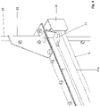
- the designated stacking box 1 comprises the ceiling frame 3 and the floor frame 7, with the ceiling frame 3 and floor frame 7 being connected by the wall elements 15 on the narrow side and the wall elements 17 on the broad side.
- the ceiling frame 3, the floor frame 7 and the wall elements 15, 17 together with the inside corner strips 19 and the floor panel 27 form the stacking box 1.
- the ceiling frame 3 is designed as a welded construction and has long ceiling frame strips 5 in relation to the wall elements 17 on the broad side and short ceiling frame strips 5 in relation to the wall elements 15 on the narrow side of the stacking box, depending on the size of the storage box.
- the cross-sectional shape of the ceiling frame strips 5 results from figure 7 in the form of an asymmetric .
- the floor frame strips 9 of the floor frame 7, which is also formed like the ceiling frame 3 as a welded construction, are in accordance with Figures 5 and 6 designed as L-profiles.
- the floor panel 27 is fixed on the floor frame 7 .
- the wall elements 15, 17 have on their underside, ie the side that is assigned to the floor panel 27, a right-angled fold 15a, 17a, with which the wall elements 15, 17 stand up on the floor frame strips 9 of the floor frame 7. Because the wall elements 15, 17 with the outwardly protruding bevel 15a, 17a form a smooth wall on the inside of the stacking box 1, there is no risk of contamination, which has to be eliminated at great expense.
- cornices 19 which are arranged on the inside between the wall elements 15 of the narrow side and the wall elements 17 of the broad side. These inner cornices 19 are connected to the wall elements by the truss-head screws already mentioned (according to DIN 603). The same applies to all screw connections that are arranged inside this stacking box.
- the stiffening angle piece 23 which also has a bevel 23a on both sides, with which the angle piece, as can be seen figure 4 results, on the fold 15a, 17a stands up.
- the foot 11 lies in a load plane with the respective internal corner strip 19 ( 4 ), thus avoiding the creation of moments due to uneven loading.
- the guide corner 21 serves to accommodate the foot 11, which is arranged at each of the four corners of the base frame 7. This means that there is no risk of the stacking boxes becoming deformed if the stacking boxes are stacked properly with the corresponding weight.
- the forklift shoes 13 On the underside of the floor frame 7 there are two forklift shoes 13 which are spaced apart from one another but run parallel to one another. The distance between the forklift shoes and the distance between the forks of a forklift truck correspond to one another.
- the forklift shoes 13 have a so-called turning holder 14 at the end, which prevents the turning holder 14 of the stacker shoe 13 from falling off the fork when the box is rotated by 180°, for example in order to completely empty the box.
- the forklift shoes 13 also ensure that the floor frame 7 is stiffened. This means that it is ensured that the stacking box does not bulge in the floor area, for example.
Landscapes
- Engineering & Computer Science (AREA)
- Mechanical Engineering (AREA)
- Stackable Containers (AREA)
Abstract
Gegenstand der Erfindung ist eine Stapelbox, insbesondere Silostapelbox, mit einem Deckenrahmen (3) und einem Bodenrahmen (7), wobei Bodenrahmen (7) und Deckenrahmen (3) durch Wandelemente (15, 17) miteinander verbunden sind, wobei die Verbindung der Wandelemente (15, 17) zwischen Deckenrahmen (3) und Bodenrahmen (7) lösbar derart ausgebildet ist, dass die Verbindung zur Lösung ohne Zerstörung der Mittel zur Bereitstellung der Verbindung ausgebildet ist.
Description
- Die Erfindung betrifft eine Stapelbox, insbesondere eine Silostapelbox.
- Stapelboxen, insbesondere Silostapelboxen unterscheiden sich von herkömmlichen Silos dadurch, dass das Fassungsvermögen solcher Stapelboxen auf ca. 1,5 bis 2,5 m3 beschränkt ist. Solche Stapelboxen dienen insbesondere der Aufnahme von kleinkörnigen landwirtschaftlichen Schüttgütern, wie zum Beispiel Saatgut, Getreide, Mais und Raps. Üblich ist, derartige Stapelboxen mit bis zu fünf Boxen übereinander zu stapeln.
- Bekannte Stapelboxen sind aus Holz oder Metall gearbeitet. Bei der Verwendung von Holz als Baustoff für solche Stapelboxen stellt sich das Problem, dass insbesondere bei mehlartigem Schüttgut die Stapelboxen nur schwerlich und daher aufwendig zu reinigen sind. Auch bei Metallboxen ergeben sich Hinterschneidungen, in die das Schüttgut eindringt, und aus denen es unbedingt wieder entfernt werden muss, sonst gibt es, wenn das Schüttgut in der Stapelbox altert, Verunreinigungen oder Vermischungen, wenn andere Schüttgüter durch die Stapelbox aufgenommen werden.
- Darüber hinaus ist ein weiterer wesentlicher Nachteil derartiger Stapelboxen zu vermerken, der darin besteht, dass die leeren Stapelboxen beim Transport im LKW relativ platzraubend sind. So können beispielsweise in einem Sattelschlepper maximal 26 Boxen transportiert werden. Die der Erfindung zugrundeliegende Aufgabe besteht demzufolge auch darin, die Transportkapazität eines LKW mit derartigen Stapelboxen signifikant zu erhöhen.
- Zur Lösung der Aufgabe wird erfindungsgemäß vorgeschlagen, dass die Stapelbox, insbesondere die Silostapelbox einen Bodenrahmen und einen Deckenrahmen aufweist, wobei der Bodenrahmen und der Deckenrahmen durch Wandelemente miteinander verbunden sind, wobei die Verbindung der Wandelemente zwischen Deckenrahmen und Bodenrahmen lösbar derart ausgebildet ist, dass die Verbindung zur Lösung ohne Zerstörung der Mittel zur Bereitstellung der Verbindung ausgebildet ist.
- Ein Sattelschlepper ist in der Lage etwa 26 zusammengebaute Boxen zu transportieren, währenddessen ein Sattelschlepper bis zu 200 Boxen transportieren kann, wenn Deckenrahmen und Bodenrahmen sowie Wandelemente jeweils gesonderte Teile sind, die auf einfache Art und Weise am Bestimmungsort zusammengebaut werden können. Dies geschieht im einfachsten Fall dadurch, dass die Wandelemente mit dem Boden- und dem Deckenrahmen jeweils verschraubt sind. Zur Verschraubung dienen insbesondere Flachrundschrauben (nach DIN 603), die einen runden Kopf haben, auf dem sich keine Ablagerungen bilden können.
- Vorteilhafte Merkmale und Ausgestaltungen zu der Erfindung ergeben sich aus den Unteransprüchen.
- So ist insbesondere vorgesehen, dass der Bodenrahmen, der aus im Querschnitt L-förmigen Bodenrahmenleisten ausgebildet ist, als Schweißkonstruktion hergestellt ist. Der Deckenrahmen weist Deckenrahmenleisten auf, die im Querschnitt nach Art eines asymmetrischenausgebildet sind. Das asymmetrische kann als großes U verstanden werden, das einen horizontalen Grundabschnitt und zwei am Grundabschnitt angeordneten Schenkel unterschiedlicher Länge aufweist. Er besitzt zur Aufnahme einer weiteren Stapelbox insofern ein hohes Widerstandsmoment gegen Durchbiegung. Deckenrahmen und Bodenrahmen sind jeweils als geschlossener Rahmen rechteckig ausgebildet, und umfassen demzufolge jeweils vier Deckenrahmenleisten beziehungsweise vier Bodenrahmenleisten.

- Nach einem weiteren besonderen Merkmal der Erfindung ist vorgesehen, dass der Bodenrahmen ausgesteift ist. Im einfachsten Fall geschieht dies dadurch, dass der Bodenrahmen mindestens eine Aussteifungstraverse aufweist, die zwei gegenüberliegende Bodenrahmenleisten verbindet. Insbesondere ist in diesem Zusammenhang vorgesehen, dass der Bodenrahmen zwei parallel und beabstandet zueinander angeordnete Staplerschuhe aufweist, die mit einem sogenannten Wendehalter versehen sein können, der bewirkt, dass dann, wenn eine solche Box von einem Stapler aufgenommen wird und zum Entleeren gedreht wird, die Stapelbox durch den Wendehalter auch bei einer 180° Drehung sicher auf der Gabel des Gabelstaplers verbleibt.
- Nach einem weiteren besonderen Merkmal der Erfindung ist vorgesehen, dass der Deckenrahmen an seinen Ecken Führungsecken zur in zwei Raumrichtungen wirkenden stapelbaren formschlüssigen Aufnahme einer weiteren Stapelbox aufweist. Das heißt, die vier Führungsecken dienen der Führung der vier Füße der auf der unteren Box gestapelten oberen Box.
- Es wurde bereits darauf hingewiesen, dass eine Silostapelbox lebensmittelhygienisch sauber sein sollte. Insofern wird bei Holzboxen immer ein erheblicher Aufwand betrieben, der zeitintensiv und infolgedessen auch kostenintensiv ist. Gleiches gilt im Wesentlichen auch für Stapelboxen aus Metall, weil solche Stapelboxen sogenannte Hinterschneidungen aufweisen, in denen sich Ablagerungen ansammeln können. Auch hier gilt, dass ein erheblicher zeitlicher Aufwand für die Reinigung erforderlich ist.
- Um den Reinigungsaufwand zu vermindern, weisen die Wandelemente bodenrahmenseitig eine rechtwinklig nach außen stehende Abkantung auf, mit welcher die Wandelemente auf dem Bodenrahmen aufstehen. Dadurch, dass die Wandelemente nach außen abgekantet sind, also mit ihrem Bund oder ihrer Abkantung nach außen auf den Bodenrahmen aufstehen, gibt es hier keine Hinterschneidungen oder sonstige Hohlräume, die erst aufwendig sauber gemacht werden müssten. Zur Verbindung der Wandelemente untereinander sind innenliegende Eckleisten vorgesehen, die lösbar mit den Wandelementen verbindbar sind. Auf der Innenseite der Stapelboxen sind die Eckleisten insofern angebracht, als hierdurch der Stoß zwischen zwei Wandelementen abgedeckt wird, und somit verhindert wird, dass sich dort Ablagerungen von einer Sorte, zum Beispiel Saatgut bilden, die für die nachfolgende Charge, zum Beispiel einer anderen Sorte Saatgut, eine Verunreinigung darstellen. Um in Bezug auf die Befestigung der Wandelemente an den Eckleisten keine Räume für Ablagerungen zu bilden, sind insbesondere sogenannte Flachrundschrauben (nach DIN 603) vorgesehen, wie dies bereits an anderer Stelle beschrieben wurde.
- Nach einem weiteren besonderen Merkmal der Erfindung weist der Bodenrahmen an seinen Ecken jeweils ein Versteifungswinkelstück auf, das außen auf die Wandelemente aufgesetzt wird. Dieses Versteifungswinkelstück, insbesondere in Verbindung mit den Führungsecken an den Ecken des Deckenrahmens, sorgt dafür, dass die Führungsecken in Verbindung mit den Versteifungswinkelstücken eine Lastachse bilden, ohne dass hierbei bei Belastung ein Moment entsteht, sodass auch gefüllte Stapelboxen aufeinander, ohne die Gefahr der Verformung, gelagert werden können. Hierbei weist das Winkelstück zu jeder Seite eine untere Abkantung zur Auflage auf der jeweiligen Abkantung der Wandelemente auf.
- Vorteilhaft an der erfindungsgemäßen Konstruktion der Stapelbox ist, dass es Teile der Stapelbox gibt, die mit dem Schüttgut in Kontakt kommen, wohingegen andere Teil der Stapelbox mit dem Schüttgut nicht in Berührung kommen. Das hat zur Folge, dass in Abhängigkeit von der Art des Schüttgutes das Material für die Wandelemente, das Bodenblech und die innenliegenden Eckleisten wählbar ist, ohne dass wesentliche weitere Bestandteile der Stapelbox, zum Beispiel Deckenrahmen und Bodenrahmen, in Bezug auf ihr Material mit ausgetauscht werden müssten. Das heißt, es ist in Abhängigkeit von der Art des Schüttgutes ein Materialmix zwischen den produktberührenden Teilen und den nicht produktberührenden Teilen der Stapelbox möglich.
- Anhand der Zeichnungen wird die Erfindung beispielhaft näher erläutert.
- Figur 1
- zeigt die Stapelbox räumlich in einer Explosionsdarstellung;
- Figur 2
- zeigt die Stapelbox räumlich im zusammengebauten Zustand;
- Figur 3
- zeigt schematisch im räumlichen Zustand zwei übereinander angeordnete Stapelboxen;
- Figur 4
- zeigt die Einzelheit IV aus
Figur 3 ; - Figur 5
- zeigt den Schnitt A-A aus der
Figur 1 ; - Figur 6
- zeigt den Schnitt B-B aus
Figur 1 ; - Figur 7
- zeigt den Schnitt C-C aus
Figur 1 . - Die mit 1 bezeichnete Stapelbox umfasst den Deckenrahmen 3 und den Bodenrahmen 7, wobei Deckenrahmen 3 und Bodenrahmen 7 durch die Wandelemente 15 der Schmalseite und die Wandelemente 17 der Breitseite verbunden ist. Der Deckenrahmen 3, der Bodenrahmen 7 und die Wandelemente 15, 17 bilden zusammen mit den innenliegenden Eckleisten 19 und dem Bodenblech 27 die Stapelbox 1.
- Der Deckenrahmen 3 ist als Schweißkonstruktion ausgebildet, und weist entsprechend der Größe der Stapelbox in Bezug auf die Wandelemente 17 der Breitseite lange Deckenrahmenleisten 5 auf sowie kurze Deckenrahmenleisten 5 in Bezug auf die Wandelemente 15 der Schmalseite der Stapelbox. Die Querschnittsform der Deckenrahmenleisten 5 ergibt sich aus
Figur 7 in Form eines asymmetrischen. An den Ecken des Deckenrahmens 3 befinden sich Führungsecken 21, die der führenden Aufnahme der Füße 11 des Bodenrahmens 7 dienen. Die Bodenrahmenleisten 9 des Bodenrahmens 7, der gleich dem Deckenrahmen 3 ebenfalls als Schweißkonstruktion ausgebildet ist, sind gemäß den
Figuren 5 und 6 als L-Profile ausgebildet. Auf dem Bodenrahmen 7 ist das Bodenblech 27 fixiert. - Die Wandelemente 15, 17 weisen an ihrer Unterseite, also der Seite, die dem Bodenblech 27 zugeordnet ist, eine rechtwinklige Abkantung 15a, 17a auf, mit der die Wandelemente 15, 17 auf den Bodenrahmenleisten 9 des Bodenrahmens 7 aufstehen. Dadurch, dass die Wandelemente 15, 17 mit der nach außen ragenden Abkantung 15a, 17a insofern eine glatte Wand auf der Innenseite der Stapelbox 1 bilden, besteht hier nicht die bereits erwähnte Gefahr der Verunreinigung, die erst mit hohem Aufwand beseitigt werden muss.
- Darüber hinaus gibt es vier Eckleisten 19, die auf der Innenseite zwischen den Wandelementen 15 der Schmalseite und den Wandelementen der Breitseite 17 angeordnet sind. Diese inneren Eckleisten 19 sind mit den Wandelementen durch die bereits benannten Flachrundschrauben (nach DIN 603) verbunden. Gleiches gilt für sämtliche Schraubverbindungen, die im Innenbereich dieser Stapelbox angeordnet sind.
- Es wurde bereits auf das Versteifungswinkelstück 23 verwiesen, das ebenfalls auf beiden Seiten eine Abkantung 23a aufweist, mit welcher das Winkelstück, wie sich dies aus
Figur 4 ergibt, auf der Abkantung 15a, 17a aufsteht. Der Fuß 11 liegt in einer Lastebene mit der jeweiligen innenliegenden Eckleiste 19 (Fig. 4 ), sodass das Entstehen von Momenten aufgrund ungleichmäßiger Belastung vermieden wird. Die Führungsecke 21 dient der Aufnahme des Fußes 11, der jeweils an den vier Ecken des Bodenrahmens 7 angeordnet ist. Das heißt, es besteht nicht die Gefahr, dass bei sachgemäßer Stapelung der Stapelboxen mit entsprechendem Gewicht sich die Stapelboxen verformen. - Auf der Unterseite des Bodenrahmens 7 befinden sich zwei beabstandet zueinander, aber parallel zueinander verlaufende Staplerschuhe 13. Der Abstand zwischen den Staplerschuhen und der Abstand der Gabeln eines Gabelstaplers korrespondieren zueinander. Die Staplerschuhe 13 weisen endseitig einen sogenannten Wendehalter 14 auf, der verhindert, dass beim Drehen der Box um 180°, um zum Beispiel die Box vollständig zu leeren, durch den Wendehalter 14 des Staplerschuhs 13 verhindert wird, dass die Stapelbox 1 von der Gabel fällt. Gleichzeitig sorgen die Staplerschuhe 13 auch dafür, dass der Bodenrahmen 7 ausgesteift wird. Das heißt, dass sichergestellt ist, dass die Stapelbox im Bodenbereich beispielsweise nicht ausbaucht.
-
- 1
- Stapelbox
- 3
- Deckenrahmen
- 5
- Deckenrahmenleiste
- 7
- Bodenrahmen
- 9
- Bodenrahmenleiste
- 11
- Fuß
- 13
- Staplerschuh
- 14
- Wendehalter des Staplerschuhs
- 15
- Wandelement (Schmalseite)
- 15a
- Abkantung (Wandelement Schmalseite)
- 17
- Wandelement (Breitseite)
- 17a
- Abkantung (Wandelement Breitseite)
- 19
- innenliegende Eckleiste
- 21
- Führungsecke am Deckenrahmen
- 23
- Versteifungswinkelstück
- 23a
- Abkantung des Versteifungswinkelstücks
- 25
- Flachrundschraube
- 27
- Bodenblech
Claims (13)
- Stapelbox (1), insbesondere Silostapelbox,
gekennzeichnet durch,
einen Deckenrahmen (3) und einen Bodenrahmen (7), wobei Bodenrahmen (7) und Deckenrahmen (3) durch Wandelemente (15, 17) miteinander verbunden sind, wobei die Verbindung der Wandelemente (15, 17) zwischen Deckenrahmen (3) und Bodenrahmen (7) lösbar derart ausgebildet ist, dass die Verbindung zur Lösung ohne Zerstörung der Mittel zur Bereitstellung der Verbindung ausgebildet ist. - Stapelbox (1), insbesondere Silostapelbox nach Anspruch 1 dadurch gekennzeichnet,
dass der Bodenrahmen (7) als Schweißkonstruktion ausgebildet ist. - Stapelbox (1), insbesondere Silostapelbox nach Anspruch 2 dadurch gekennzeichnet,
dass der Bodenrahmen (7) im Querschnitt L-förmige Bodenrahmenleisten (9) aufweist. - Stapelbox (1), insbesondere Silostapelbox nach einem der voranstehenden Ansprüche,
dadurch gekennzeichnet,
dass der Bodenrahmen (7) als geschlossener Rahmen rechteckig ausgebildet ist. - Stapelbox (1), insbesondere Silostapelbox, nach einem der voranstehenden Ansprüche,
dadurch gekennzeichnet,
dass der Bodenrahmen (7) zwei parallel und beabstandet zueinander angeordnete Staplerschuhe (13) aufweist. - Stapelbox (1), insbesondere Silostapelbox, nach einem der voranstehenden Ansprüche,
dadurch gekennzeichnet,
dass der Deckenrahmen (3) als Schweißkonstruktion ausgebildet ist. - Stapelbox (1), insbesondere Silostapelbox, nach einem der voranstehenden Ansprüche,
dadurch gekennzeichnet,
dass der Deckenrahmen (3) im Querschnitt-förmige Deckenrahmenleisten (5) aufweist.
- Stapelbox (1), insbesondere Silostapelbox, nach einem der voranstehenden Ansprüche,
dadurch gekennzeichnet,
dass der Deckenrahmen (3) als geschlossener Rahmen rechteckig ausgebildet ist. - Stapelbox (1), insbesondere Silostapelbox, nach Anspruch 8,
dadurch gekennzeichnet,
dass der Deckenrahmen (3) an seinen Ecken Führungsecken (21) zur in zwei Raumrichtungen wirkenden, stapelbaren, formschlüssigen Aufnahme der Füße (11) einer weiteren Stapelbox (1) aufweist. - Stapelbox (1), insbesondere Silostapelbox, nach einem der voranstehenden Ansprüche,
dadurch gekennzeichnet,
dass die Wandelemente (15, 17) bodenrahmenseitig eine rechtwinklig, nach außen abstehende Abkantung (15a, 17a) aufweisen, mit welcher die Wandelemente (15, 17) auf dem Bodenrahmen (7) aufstehen. - Stapelbox (1), insbesondere Silostapelbox, nach einem der voranstehenden Ansprüche,
dadurch gekennzeichnet,
dass die Wandelemente (15, 17) durch innere Eckleisten (19) auf der Innenseite der Wandelemente (15, 17) miteinander lösbar verbunden sind. - Stapelbox (1), insbesondere Silostapelbox, nach einem der voranstehenden Ansprüche,
dadurch gekennzeichnet,
dass der Bodenrahmen (7) an seinen Ecken jeweils ein Versteifungswinkelstück (23) aufweist, das außen auf die Wandelemente (15, 17) aufgesetzt ist. - Stapelbox (1), insbesondere Silostapelbox, nach Anspruch 12, dadurch gekennzeichnet,
dass das Versteifungswinkelstück (23) zu jeder Seite eine untere Abkantung (23a) zur Auflage auf der jeweiligen Abkantung (15a, 17a) der Wandelemente (15, 17) aufweist.
Applications Claiming Priority (2)
| Application Number | Priority Date | Filing Date | Title |
|---|---|---|---|
| DE202021104289 | 2021-08-11 | ||
| DE202021104382.2U DE202021104382U1 (de) | 2021-08-11 | 2021-08-17 | Stapelbox, insbesondere Silostapelbox |
Publications (1)
| Publication Number | Publication Date |
|---|---|
| EP4134320A1 true EP4134320A1 (de) | 2023-02-15 |
Family
ID=82656553
Family Applications (1)
| Application Number | Title | Priority Date | Filing Date |
|---|---|---|---|
| EP22186297.2A Withdrawn EP4134320A1 (de) | 2021-08-11 | 2022-07-21 | Stapelbox, insbesondere silostapelbox |
Country Status (1)
| Country | Link |
|---|---|
| EP (1) | EP4134320A1 (de) |
Citations (4)
| Publication number | Priority date | Publication date | Assignee | Title |
|---|---|---|---|---|
| US3809278A (en) * | 1971-11-02 | 1974-05-07 | Central Steel Works Ltd | Collapsible shipping container |
| AU6213973A (en) * | 1972-11-10 | 1975-05-08 | Beckley M D | Structures |
| DE8421156U1 (de) * | 1984-07-14 | 1984-08-30 | Peltzer-Werke GmbH & Co KG, 5190 Stolberg | Zerlegbarer Behaelter |
| US20190241314A1 (en) * | 2013-03-15 | 2019-08-08 | Convertible Trailer Patent Company Ltd. | Inter-modal shipping mini-containers and method of using same |
-
2022
- 2022-07-21 EP EP22186297.2A patent/EP4134320A1/de not_active Withdrawn
Patent Citations (4)
| Publication number | Priority date | Publication date | Assignee | Title |
|---|---|---|---|---|
| US3809278A (en) * | 1971-11-02 | 1974-05-07 | Central Steel Works Ltd | Collapsible shipping container |
| AU6213973A (en) * | 1972-11-10 | 1975-05-08 | Beckley M D | Structures |
| DE8421156U1 (de) * | 1984-07-14 | 1984-08-30 | Peltzer-Werke GmbH & Co KG, 5190 Stolberg | Zerlegbarer Behaelter |
| US20190241314A1 (en) * | 2013-03-15 | 2019-08-08 | Convertible Trailer Patent Company Ltd. | Inter-modal shipping mini-containers and method of using same |
Similar Documents
| Publication | Publication Date | Title |
|---|---|---|
| DE60106881T2 (de) | Palettenkäfig | |
| DE3301159A1 (de) | In drei ebenen wahlweise uebereinander und ineinander stapelbare container | |
| DE10009272A1 (de) | Zusammenlegbarer Behälter | |
| DE3530350C2 (de) | ||
| DE7909924U1 (de) | Palettenbehaelter | |
| CH707201A2 (de) | Fixierelement zur Positionierung quaderförmiger Behälter in einem vertikalen Stapel. | |
| DE4143023C2 (de) | Klappbarer Rahmen für eine Transport- oder Lagerbox | |
| DE60319376T2 (de) | Zusammenlegbarer Behälter | |
| DE202007011002U1 (de) | Behältersystem | |
| EP4134320A1 (de) | Stapelbox, insbesondere silostapelbox | |
| DE202021104382U1 (de) | Stapelbox, insbesondere Silostapelbox | |
| DE202017103226U1 (de) | Faltbare Transportverpackung aus Wellpappe mit einteiligem Boden | |
| DE202023101620U1 (de) | Zarge für die Beute von Bienen | |
| CH496579A (de) | Transportmittel | |
| DE2926621C2 (de) | Bauelement zur Herstellung ptismatischer Wandkonstruktionen | |
| DE3741350C2 (de) | ||
| DE102012000242B4 (de) | Stapelbare Warenpalette | |
| DE2233825C2 (de) | Zusammenlegbarer Behälter | |
| DE1124421B (de) | Behaelter | |
| DE19708824A1 (de) | Verfahren und Einrichtung zur Stapelung von Containern auf einem Boden und ein Containerstapel | |
| DE2628305C3 (de) | Zerlegbarer Transportbehälter, für Obst und Gärtnereierzeugnisse | |
| DE2152698A1 (de) | Zusammenlegbarer transportbehaelter | |
| DE2206439A1 (de) | Behalter und Verfahren zur Her stellung des Behalters | |
| DE4302640C1 (de) | Demontierbare Verpackungseinheit | |
| EP2987742A1 (de) | Stapelbarer behälter mit lastübertragungsstruktur |
Legal Events
| Date | Code | Title | Description |
|---|---|---|---|
| PUAI | Public reference made under article 153(3) epc to a published international application that has entered the european phase |
Free format text: ORIGINAL CODE: 0009012 |
|
| STAA | Information on the status of an ep patent application or granted ep patent |
Free format text: STATUS: THE APPLICATION HAS BEEN PUBLISHED |
|
| AK | Designated contracting states |
Kind code of ref document: A1 Designated state(s): AL AT BE BG CH CY CZ DE DK EE ES FI FR GB GR HR HU IE IS IT LI LT LU LV MC MK MT NL NO PL PT RO RS SE SI SK SM TR |
|
| STAA | Information on the status of an ep patent application or granted ep patent |
Free format text: STATUS: THE APPLICATION IS DEEMED TO BE WITHDRAWN |
|
| 18D | Application deemed to be withdrawn |
Effective date: 20230817 |