EP4134478A1 - Appareil d'entretien des vêtements et son procédé de fabrication - Google Patents
Appareil d'entretien des vêtements et son procédé de fabrication Download PDFInfo
- Publication number
- EP4134478A1 EP4134478A1 EP21808278.2A EP21808278A EP4134478A1 EP 4134478 A1 EP4134478 A1 EP 4134478A1 EP 21808278 A EP21808278 A EP 21808278A EP 4134478 A1 EP4134478 A1 EP 4134478A1
- Authority
- EP
- European Patent Office
- Prior art keywords
- clothing care
- care apparatus
- coating layer
- print layer
- layer
- Prior art date
- Legal status (The legal status is an assumption and is not a legal conclusion. Google has not performed a legal analysis and makes no representation as to the accuracy of the status listed.)
- Pending
Links
Images



Classifications
-
- D—TEXTILES; PAPER
- D06—TREATMENT OF TEXTILES OR THE LIKE; LAUNDERING; FLEXIBLE MATERIALS NOT OTHERWISE PROVIDED FOR
- D06F—LAUNDERING, DRYING, IRONING, PRESSING OR FOLDING TEXTILE ARTICLES
- D06F34/00—Details of control systems for washing machines, washer-dryers or laundry dryers
- D06F34/28—Arrangements for program selection, e.g. control panels therefor; Arrangements for indicating program parameters, e.g. the selected program or its progress
- D06F34/32—Arrangements for program selection, e.g. control panels therefor; Arrangements for indicating program parameters, e.g. the selected program or its progress characterised by graphical features, e.g. touchscreens
-
- D—TEXTILES; PAPER
- D06—TREATMENT OF TEXTILES OR THE LIKE; LAUNDERING; FLEXIBLE MATERIALS NOT OTHERWISE PROVIDED FOR
- D06F—LAUNDERING, DRYING, IRONING, PRESSING OR FOLDING TEXTILE ARTICLES
- D06F73/00—Apparatus for smoothing or removing creases from garments or other textile articles by formers, cores, stretchers, or internal frames, with the application of heat or steam
- D06F73/02—Apparatus for smoothing or removing creases from garments or other textile articles by formers, cores, stretchers, or internal frames, with the application of heat or steam having one or more treatment chambers
-
- C—CHEMISTRY; METALLURGY
- C03—GLASS; MINERAL OR SLAG WOOL
- C03C—CHEMICAL COMPOSITION OF GLASSES, GLAZES OR VITREOUS ENAMELS; SURFACE TREATMENT OF GLASS; SURFACE TREATMENT OF FIBRES OR FILAMENTS MADE FROM GLASS, MINERALS OR SLAGS; JOINING GLASS TO GLASS OR OTHER MATERIALS
- C03C17/00—Surface treatment of glass, not in the form of fibres or filaments, by coating
- C03C17/001—General methods for coating; Devices therefor
- C03C17/002—General methods for coating; Devices therefor for flat glass, e.g. float glass
-
- C—CHEMISTRY; METALLURGY
- C03—GLASS; MINERAL OR SLAG WOOL
- C03C—CHEMICAL COMPOSITION OF GLASSES, GLAZES OR VITREOUS ENAMELS; SURFACE TREATMENT OF GLASS; SURFACE TREATMENT OF FIBRES OR FILAMENTS MADE FROM GLASS, MINERALS OR SLAGS; JOINING GLASS TO GLASS OR OTHER MATERIALS
- C03C17/00—Surface treatment of glass, not in the form of fibres or filaments, by coating
- C03C17/34—Surface treatment of glass, not in the form of fibres or filaments, by coating with at least two coatings having different compositions
- C03C17/3411—Surface treatment of glass, not in the form of fibres or filaments, by coating with at least two coatings having different compositions with at least two coatings of inorganic materials
- C03C17/3429—Surface treatment of glass, not in the form of fibres or filaments, by coating with at least two coatings having different compositions with at least two coatings of inorganic materials at least one of the coatings being a non-oxide coating
-
- C—CHEMISTRY; METALLURGY
- C03—GLASS; MINERAL OR SLAG WOOL
- C03C—CHEMICAL COMPOSITION OF GLASSES, GLAZES OR VITREOUS ENAMELS; SURFACE TREATMENT OF GLASS; SURFACE TREATMENT OF FIBRES OR FILAMENTS MADE FROM GLASS, MINERALS OR SLAGS; JOINING GLASS TO GLASS OR OTHER MATERIALS
- C03C17/00—Surface treatment of glass, not in the form of fibres or filaments, by coating
- C03C17/34—Surface treatment of glass, not in the form of fibres or filaments, by coating with at least two coatings having different compositions
- C03C17/3411—Surface treatment of glass, not in the form of fibres or filaments, by coating with at least two coatings having different compositions with at least two coatings of inorganic materials
- C03C17/3429—Surface treatment of glass, not in the form of fibres or filaments, by coating with at least two coatings having different compositions with at least two coatings of inorganic materials at least one of the coatings being a non-oxide coating
- C03C17/3435—Surface treatment of glass, not in the form of fibres or filaments, by coating with at least two coatings having different compositions with at least two coatings of inorganic materials at least one of the coatings being a non-oxide coating comprising a nitride, oxynitride, boronitride or carbonitride
-
- D—TEXTILES; PAPER
- D06—TREATMENT OF TEXTILES OR THE LIKE; LAUNDERING; FLEXIBLE MATERIALS NOT OTHERWISE PROVIDED FOR
- D06F—LAUNDERING, DRYING, IRONING, PRESSING OR FOLDING TEXTILE ARTICLES
- D06F34/00—Details of control systems for washing machines, washer-dryers or laundry dryers
- D06F34/28—Arrangements for program selection, e.g. control panels therefor; Arrangements for indicating program parameters, e.g. the selected program or its progress
- D06F34/30—Arrangements for program selection, e.g. control panels therefor; Arrangements for indicating program parameters, e.g. the selected program or its progress characterised by mechanical features, e.g. buttons or rotary dials
-
- D—TEXTILES; PAPER
- D06—TREATMENT OF TEXTILES OR THE LIKE; LAUNDERING; FLEXIBLE MATERIALS NOT OTHERWISE PROVIDED FOR
- D06F—LAUNDERING, DRYING, IRONING, PRESSING OR FOLDING TEXTILE ARTICLES
- D06F34/00—Details of control systems for washing machines, washer-dryers or laundry dryers
- D06F34/28—Arrangements for program selection, e.g. control panels therefor; Arrangements for indicating program parameters, e.g. the selected program or its progress
- D06F34/34—Arrangements for program selection, e.g. control panels therefor; Arrangements for indicating program parameters, e.g. the selected program or its progress characterised by mounting or attachment features, e.g. detachable control panels or detachable display panels
-
- D—TEXTILES; PAPER
- D06—TREATMENT OF TEXTILES OR THE LIKE; LAUNDERING; FLEXIBLE MATERIALS NOT OTHERWISE PROVIDED FOR
- D06F—LAUNDERING, DRYING, IRONING, PRESSING OR FOLDING TEXTILE ARTICLES
- D06F58/00—Domestic laundry dryers
- D06F58/10—Drying cabinets or drying chambers having heating or ventilating means
-
- C—CHEMISTRY; METALLURGY
- C03—GLASS; MINERAL OR SLAG WOOL
- C03C—CHEMICAL COMPOSITION OF GLASSES, GLAZES OR VITREOUS ENAMELS; SURFACE TREATMENT OF GLASS; SURFACE TREATMENT OF FIBRES OR FILAMENTS MADE FROM GLASS, MINERALS OR SLAGS; JOINING GLASS TO GLASS OR OTHER MATERIALS
- C03C2217/00—Coatings on glass
- C03C2217/70—Properties of coatings
- C03C2217/72—Decorative coatings
-
- C—CHEMISTRY; METALLURGY
- C03—GLASS; MINERAL OR SLAG WOOL
- C03C—CHEMICAL COMPOSITION OF GLASSES, GLAZES OR VITREOUS ENAMELS; SURFACE TREATMENT OF GLASS; SURFACE TREATMENT OF FIBRES OR FILAMENTS MADE FROM GLASS, MINERALS OR SLAGS; JOINING GLASS TO GLASS OR OTHER MATERIALS
- C03C2218/00—Methods for coating glass
- C03C2218/30—Aspects of methods for coating glass not covered above
- C03C2218/32—After-treatment
- C03C2218/328—Partly or completely removing a coating
-
- C—CHEMISTRY; METALLURGY
- C03—GLASS; MINERAL OR SLAG WOOL
- C03C—CHEMICAL COMPOSITION OF GLASSES, GLAZES OR VITREOUS ENAMELS; SURFACE TREATMENT OF GLASS; SURFACE TREATMENT OF FIBRES OR FILAMENTS MADE FROM GLASS, MINERALS OR SLAGS; JOINING GLASS TO GLASS OR OTHER MATERIALS
- C03C2218/00—Methods for coating glass
- C03C2218/30—Aspects of methods for coating glass not covered above
- C03C2218/32—After-treatment
- C03C2218/328—Partly or completely removing a coating
- C03C2218/33—Partly or completely removing a coating by etching
-
- D—TEXTILES; PAPER
- D06—TREATMENT OF TEXTILES OR THE LIKE; LAUNDERING; FLEXIBLE MATERIALS NOT OTHERWISE PROVIDED FOR
- D06F—LAUNDERING, DRYING, IRONING, PRESSING OR FOLDING TEXTILE ARTICLES
- D06F34/00—Details of control systems for washing machines, washer-dryers or laundry dryers
- D06F34/28—Arrangements for program selection, e.g. control panels therefor; Arrangements for indicating program parameters, e.g. the selected program or its progress
Definitions
- the present invention relates to a clothing care apparatus for removing dust attached to clothes or odors in the clothes and a manufacturing method therefor.
- Clothing care apparatuses are an apparatus for performing clothes care, such as drying wet clothes, removing dust attached to clothes, or removing odors ingrained in clothes, and decreasing creases on clothes.
- the clothing care apparatus includes a body provided with a chamber configured to accommodate and take care of clothes, and a door configured to open and close the chamber.
- a compressor and a heat exchange device configured to supply dry air to the clothes are provided inside the body, and a steam generation device configured to supply steam to the clothes is provided therein.
- the clothing care apparatus functions to supply air or hot air generated by a blowing device to the clothes to remove dust attached to the clothes or odors ingrained in the clothes, and spray the steam generated from the steam generation device to smooth the creases formed on the clothes.
- the present invention is directed to providing a clothing care apparatus which can not only secure reflectivity and visibility by introducing a door glass having a new laminated structure, but also solve a malfunction problem due to electrical conduction, and a manufacturing method therefor.
- a clothing care apparatus includes a body including a clothing care room, and a door rotatably coupled to the body and including a control panel on a front surface thereof, wherein the control panel includes a glass, a coating layer provided on an upper surface of the glass while having a gap, a first print layer laminated in a shape corresponding to an upper surface of the coating layer, and a second print layer laminated on an upper surface of the first print layer and provided adjacent to the glass.
- the coating layer may contain one or more selected from the group consisting of SiN x or SiNO x and a combination thereof.
- the coating layer may further contain one or more selected from the group consisting of Al x O y , Nb x O y , and SiO x .
- the coating layer may further contain one or more selected from the group consisting of Si, Ni, Cr, Nb, Zr, Co, Ti, and Ag nanoparticles.
- a content of SiN x or SiNO x may be in a range of 70 to 90 wt%.
- the coating layer may be provided with a thickness of 30 to 100 nm.
- a resistance of the coating layer may be 500 M ⁇ or more.
- a reflectivity of the control panel may be 70 % or less, and a transmittance thereof may be 20 % or more.
- the reflectivity of the control panel may be in a range of 20 to 70 %, and the transmittance thereof may be in a range of 20 to 70 %.
- the glass may have a thickness of 2 to 6 mm.
- the control panel may further include a protective layer formed on an upper surface of the second print layer.
- the protective layer may be made of one or more selected from the group consisting of a metal oxide, a metal nitride, a metal oxynitride, and a combination thereof.
- the first print layer may be provided in black, burgundy, pink, ivory, and gold colors.
- a logo or a user interface may be implemented.
- the door may be provided with a width of 18 to 25 inches.
- a manufacturing method of a clothing care apparatus includes forming a coating layer by applying one or more selected from the group consisting of SiN x or SiNO x and a combination thereof to a mother glass, laminating a color print layer after performing strengthening heat treatment on the formed coating layer, etching the coating layer and the color print layer with a fiber laser, and forming a logo/UI print layer so as to be adjacent to the glass and laminated on an upper surface of the color print layer.
- An application frequency of the fiber laser may be in a range of 50 to 100 Hz.
- the etching of the coating layer and the color print layer with the fiber laser may be performed for 10 seconds to 60 seconds.
- the strengthening heat treatment may be performed in a range of 650 to 700 °C.
- the method may further include forming a protective layer on an upper surface of the logo/UI print layer.
- a clothing care apparatus and a manufacturing method therefor According to a clothing care apparatus and a manufacturing method therefor according to one aspect, it is possible to provide a clothing care apparatus and a manufacturing method therefor which can not only secure reflectivity and visibility of a door, but also solve a malfunction problem due to electrical conduction.
- a clothing care apparatus includes a body including a clothing care room, and a door rotatably coupled to the body and including a control panel on a front surface thereof, wherein the control panel includes a glass, a coating layer provided on an upper surface of the glass while having a gap, a first print layer laminated in a shape corresponding to an upper surface of the coating layer, and a second print layer laminated on an upper surface of the first print layer, and provided adjacent to the glass.
- first and/or second may be used to describe various components, but the components are not limited by the terms, and the terms are used only for the purpose of distinguishing one component from other components.
- a first component may be named as a second component, and similarly, the second component may also be named as the first component without departing from the scope of the present invention.
- each operation is used to identify each operation, and these symbols do not indicate the order between the operations, and each operation may be performed differently from the stated order unless the context clearly indicates a specific order.
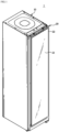
- FIG. 1 is a perspective view showing a clothing care apparatus according to an embodiment of the present invention
- FIG. 2 is a view showing a state in which a door of the clothing care apparatus according to the embodiment of the present invention is opened
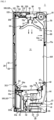
- FIG. 3 is a side cross-sectional view showing the clothing care apparatus according to the embodiment of the present invention
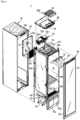
- FIG. 4 is an exploded perspective view showing the clothing care apparatus according to the embodiment of the present invention.
- a clothing care apparatus 1 includes a body 10 forming an exterior, a door 20 rotatably coupled to the body 10, a clothing care room 11 provided inside the body 10 and configured to accommodate and take care of clothes, a clothing support member 50 provided inside the clothing care room 11 and provided to hold the clothes, and a machine room 13 provided with a heat exchange device 30 provided to dehumidify or heat air inside the clothing care room 11.
- the body 10 may include the clothing care room 11 formed therein, and have a hexahedral shape with one surface open.
- An opening 10a is formed on a front surface of the body 10.
- the door 20 rotatably coupled thereto and configured to open and close the clothing care room 11 is installed in the opening 10a of the body 10.
- the door 20 may be installed through a connection member such as a hinge or a link.
- the clothing care room 11 forms a space in which clothes are accommodated.
- the clothing care room 11 may include an upper surface 10b, a lower surface 10b, a left surface 10c, a right surface 10d, and a rear surface 10f, which are provided inside the body 10.
- the front surface of the clothing care room 11 is formed to be open. Accordingly, the opening of the clothing care room 11 may also be opened and closed together by the door 20 configured to open and close the opening 10a of the body 10.
- a discharge bracket 16 installed at a position corresponding to a discharge flow path 120 of the door 20 to be described below may be provided at an upper end of the opening 10a of the body 10.
- the discharge bracket 16 may include a plurality of discharge slits 16a disposed to correspond to the discharge flow path 120 of the door 20.
- the clothing support member 50 provided so that clothes may be held and supported is provided inside the clothing care room 11.
- the clothing support member 50 may be installed on the upper surface 10b of the clothing care room 11.
- the clothing support member 50 may be separably installed in the clothing care room 11.
- At least one clothing support member 50 may be provided.
- the clothing support member 50 may be formed in a shape of a hanger so that clothes may be fitted thereto.
- the clothing support member 50 is provided so that air may flow therein. Dust or foreign substances attached to the clothes may be removed by the air supplied to the inside of the clothing support member 50.
- An air hole 51 configured to supply air to the clothes may be formed in the clothing support member 50.
- the air hole is formed at an upper end of the clothing support member, and the air supplied through the air hole at the upper end is supplied to the inside and outside of the clothes as an example, but the spirit of the present invention is not limited thereto.
- the air hole may be formed in various sizes at various positions so that the supplied air may be widely sprayed to the clothes.
- the clothing care room 11 may include a first airflow inlet 11a and a second airflow inlet 12a, a first airflow outlet 11b and a second airflow outlet 12b, and a steam outlet 43.
- the first airflow inlet 11a and the first airflow outlet 11b may be formed on the lower surface 10b of the clothing care room 11.
- the first airflow inlet 11a may be disposed in front of the lower surface 10b of the clothing care room 11.
- the first airflow outlet 11b may be disposed behind the lower surface 10b of the clothing care room 11.
- the first airflow inlet 11a and the first airflow outlet 1 1b may be disposed at positions adjacent to each other.
- the steam outlet 43 may be disposed on a lower portion of the rear surface 10f of the clothing care room 11.
- the steam outlet 43 may be disposed above the first airflow outlet 11b.
- the second airflow inlet 12a may be formed on an upper portion of the rear surface 10f of the clothing care room 11.
- the second airflow outlet 12b may be formed in a center of the upper surface 10b of the clothing care room 11.
- the second airflow inlet 12a and the second airflow outlet 12b may be disposed at positions adjacent to each other.
- the second airflow outlet 12b of the clothing care room 11 may be connected to the clothing support member 50.
- the air discharged through the second airflow outlet 12b is transmitted to the clothing support member 50 through the air hole 51 and transmitted to the clothes held on the clothing support member 50.
- a water drain tank 15a and a water supply tank 15b which are provided separably from the body 10 may be installed on a lower portion of the body 10.
- the water drain tank 15a and the water supply tank 15b may be disposed under the clothing care room 11.
- the water drain tank 15a is provided to facilitate the condensed water treatment.
- the water supply tank 15b stores water required for generating steam in a steam generation device 40 to be described below.
- the water in the water supply tank 15b is supplied to the steam generation device 40 and used to form steam.
- the water supply tank 15b may be installed separably from the body 10 to facilitate water replenishment.
- the water drain tank 15a and the water supply tank 15b may be provided in front of the machine room 13.
- the machine room 13 is provided on a lower side of the body 10.
- the machine room 13 is provided under the clothing care room 11.
- the machine room 13 may include a heat exchange device 30 provided to dehumidify and heat the air inside the clothing care room 11 as necessary.
- a blowing fan 32, the heat exchange device 30, and the steam generation device 40 may be disposed inside the machine room 13.
- the heat exchange device 30 is installed to supply hot air to the inside of the clothing care room 11.
- the heat exchange device 30 includes an evaporator 33, a compressor 35, and a condenser 34 through which refrigerant circulates, and is provided to dehumidify and heat air.
- the latent heat of the surrounding air is absorbed to condense and remove moisture in the air.
- the refrigerant is condensed in the condenser 34 by passing through the compressor 35, the latent heat is discharged toward the surrounding air to heat the surrounding air.
- the evaporator 33 and the condenser 34 function as a heat exchanger, the air introduced into the machine room 13 by the blowing fan 32 is dehumidified and heated by sequentially passing through the evaporator 33 and the condenser 34.
- the heat exchange device 30 installed in the machine room 13 may include a first duct 31 configured to connect the evaporator 33, the condenser 34, and the blowing fan 32, and the first duct 31 may be connected to the clothing care room 11 to form a first circulation flow path 39 which circulates between the clothing care room 11 and the first duct 31.
- the first duct 31 may be connected to the first airflow inlet 11a and the first airflow outlet 1 1b of the clothing care room 11.
- One end of the first duct 31 may be connected to the first airflow inlet 11a of the clothing care room 11, and the other end thereof may be connected to the first airflow outlet 1 1b of the clothing care room 11.
- a first duct inlet 31a of the first duct 31 may be connected to the first airflow inlet 11a and a first duct outlet 31b thereof may be connected to the first airflow outlet 11b.
- the air in the clothing care room 11 is introduced into the first duct 31 through the first airflow inlet 11a, and the introduced air is dehumidified and discharged back to the clothing care room 11 through the first airflow outlet 11b.
- the first airflow inlet is disposed in the front of the clothing care room and the first airflow outlet is disposed in the rear of the clothing care room as an example, but the spirit of the present invention is not limited thereto.
- the positions of the airflow inlet and the airflow outlet may be variously changed as necessary.
- the first duct 31 is provided to dehumidify the air introduced through the first airflow inlet 11a and discharge the introduced air to the first airflow outlet 11b.
- the blowing fan 32 is provided on the first duct 31 and provided to suck the air in the clothing care room 11 to the inside of the first duct 31.
- the machine room 13 may further include the steam generation device 40 configured to receive water from the water supply tank 15b to form steam.
- the steam generation device 40 may be disposed in the machine room 13.
- the steam generation device 40 may include a steam generator 41 connected to the water supply tank 15b and configured to receive water and generate steam, and a steam supply tube 44 configured to guide the generated steam to a steam sprayer 42.
- the steam sprayer 42 may be disposed on a lower rear surface of the clothing care room 11.
- a heater (not shown) may be installed inside the steam generator 41 to heat water.
- the clothing care room 11 may include a blowing device 72 configured to flow air therein.
- the clothing care room 11 may include a second duct 71, and the blowing device 72 may be installed inside the second duct 71.
- the second duct 71 may be provided to communicate with the clothing care room 11 to form a second circulation flow path 70 which circulates between the clothing care room 11 and the second duct 71.
- the blowing device 72 may be disposed on the second circulation flow path 70.
- the second duct 71 may be formed behind the second airflow inlet 12a of the clothing care room 11.
- the second duct 71 may be provided on an upper rear surface of the clothing care room 11 and may include a filter member 60 therein.
- the second duct 71 may be coupled to a top cover 80 disposed on an upper portion of the clothing care room 11.
- the second duct 71 may be coupled to the top cover 80 and the blowing device 72 may be installed therein.
- the blowing device 72 is disposed on an upper rear side of the clothing care room 11, and may include a blowing motor 72a configured to generate a rotational force and at least one blowing fan 72b rotated by the blowing motor.
- the blowing fan 72b may be accommodated by a fan case 72c.
- the fan case 72c may be coupled to a duct bracket 74 provided on the upper surface 10b of the clothing care room 11. At least one duct hole 74a is formed on the duct bracket 74, and the blowing fan 32 is coupled to each of the at least one duct hole 74a to move the air in the second duct 71 to the second airflow outlet 12b of the second duct 71.
- the second duct 71 may be connected to the second airflow inlet 12a and the second airflow outlet 12b of the clothing care room 11.
- One end of the second duct 71 may be connected to the second airflow inlet 12a of the clothing care room 11, and the other end thereof may be connected to the second airflow outlet 12b of the clothing care room 11.
- the second duct inlet 71a of the second duct 71 may be connected to the second airflow inlet 12a and the second duct outlet 71b may be connected to the second airflow outlet 12b.
- the second airflow outlet 12b of the clothing care room 11 may be formed at a position corresponding to the second duct outlet 71b of the second duct 71.
- the second duct outlet 71b of the second duct 71 is connected to the second airflow outlet 12b of the clothing care room 11, and the second airflow outlet 12b is connected to the clothing support member 50 so that the air in the second duct 71 is transmitted to the clothing support member 50.
- the blowing device 72 disposed inside the second duct 71 is provided to suck the air inside the clothing care room 11 through the second airflow inlet 12a and discharge the sucked air to the second duct outlet 71b and the second airflow outlet 12b.
- the filter member 60 is provided on the second airflow inlet 12a of the clothing care room 11.
- the second airflow inlet 12a is formed on the rear surface 10f of the clothing care room 11.
- a filter member installation portion 11c configured to install the filter member 60 is provided on the rear surface 10f of the clothing care room 11.
- the second airflow inlet 12a may be formed at a position corresponding to the filter member installation portion 11c.
- the air inside the clothing care room 11 may be filtered by the filter member 60 of the second airflow inlet 12a when introduced into the second duct 71. Dust and odors in the air introduced into the second duct 71 may be removed by the filter member 60. The air filtered by the filter member 60 may be discharged to the second duct outlet 71b and the clothing support member 50 through the blowing device 72.
- the filter member 60 may include a dust collection filter (not shown) configured to remove dust or a means for deodorizing.
- the clothing care room 11 operates in a state in which clothes are held on the clothing support member 50 and the door 20 is closed when taking care of the clothes. At this time, in the clothing care room 11, air may be circulated along the first circulation flow path 39 and the second circulation flow path 70.
- the clothing care apparatus 1 includes a dehumidification flow path 100 provided on the door 20 to connect the clothing care room 11 and the outside when dehumidifying an interior.
- the dehumidification flow path 100 may be provided on the door 20. At least one dehumidification flow path 100 may be formed.
- FIG. 5 is a partial exploded perspective view showing the dehumidification flow path of the door of the clothing care apparatus according to the embodiment of the present invention.
- the door 20 may include the dehumidification flow path 100 which communicates the clothing care room 11 with the outside.
- the door 20 includes a first door member 21 configured to form a front surface, and a second door member 22 coupled to the first door member 21 to form a rear surface.
- the dehumidification flow path 100 may be formed between the first door member 21 and the second door member 22. At least one of the dehumidification flow paths 100 may be formed between the first door member 21 and the second door member 22. The dehumidification flow path 100 may be formed on at least one of the first door member 21 and the second door member 22.
- the dehumidification flow path 100 may be provided on the door 20, and may include an introduction flow path 110 for introducing outside air into the inside of the clothing care room 11, and a discharge flow path 120 for discharging the air inside the clothing care room 11 to the outside.
- the first door member 21 is formed in a plate shape.
- the first door member 21 may include a mirror, a glass, a panel, and the like.
- the first door member 21 is a plate-shaped mirror as an example, but the spirit of the present invention is not limited thereto.
- the first door member may include covers made of various materials which are coupled to have a sense of unity with furniture in the interior where the clothing care apparatus 1 is installed.
- the first door member 21 may be installed in front of the second door member 22 to form the exterior of the clothing care apparatus 1.
- the second door member 22 may include a first door member installation portion 311 configured to install the first door member 21.
- the first door member installation portion 311 may be disposed in front of the second door member 22.
- the second door member 22 may further include a door frame 300.
- the door frame 300 may include a first door frame 310 and a second door frame 320 coupled to the rear of the first door frame 310.
- the first door member installation portion 311 may be provided on a front surface of the first door frame 310.
- the dehumidification flow path 100 may be provided on the first door frame 310.
- the introduction flow path 110 may be provided on the first door frame 310.
- the introduction flow path 110 is provided to move the air introduced through a first inlet 111 and discharge the air to the clothing care room 11 through a first outlet 112.
- the introduction flow path 110 may include an introduction flow path duct 130 configured to guide the air introduced through the first inlet 111 to move.
- the first outlet 112 may be formed on the introduction flow path duct 130.
- the introduction flow path 110 may include a first damping device 210 provided to open and close the first outlet 112.
- the first damping device 210 may be provided inside the introduction flow path duct 130.
- At least one surface of the first door frame 310 is provided with the first inlet 111 formed so that outside air may be introduced.
- the first inlet 111 is formed on a bottom surface of the first door frame 310.
- a plurality of first inlets 111 may be formed.
- An airflow introduction space 312 in which the air introduced into the first inlet 111 is accommodated may be formed between the first door frame 310 and the first door member 21.
- An airflow introduction hole 313 may be formed in the airflow introduction space 312.
- the airflow introduction hole 313 may be formed in the first door frame 310.
- the second door frame 320 may be formed to have a size and shape corresponding to the opening 10a of the body 10.
- the second door frame 320 is provided to come into contact with the body 10 to open and close the opening 10a.
- the second door frame 320 may be provided with the dehumidification flow path 100.
- the introduction flow path 110 may be provided on the first door frame 310.
- the introduction flow path duct 130 of the introduction flow path 110 may be provided on the second door frame 320.
- the introduction flow path duct 130 may be installed at a position corresponding to the airflow introduction hole 313 of the first door frame 310.
- the outside air introduced through the first inlet 111 of the first door frame 310 is transmitted to the introduction flow path duct 130 through the airflow introduction space 312 and the airflow introduction hole 313.
- the clothing care apparatus 1 may include the body 10 and the door 20 rotatably coupled to the body 10.
- the clothing care room 11 configured to accommodate and take care of clothes may be provided inside the body, and the door 20 may be rotatably installed on one side of the front surface of the body 10 to open and close the clothing care room 11.
- the door 20 may be installed through a connection member such as a hinge or a link, and the door 20 may be provided to have a width of 18 to 24 inches.
- the first door member 21 may include a control panel 210 provided so that a user selects an operation of the clothing care apparatus 1.
- the control panel 210 provided on the front side of the door 20 may receive a user's input (e.g., a touch or button selection), and display an application (or widget included) screen.
- the control panel 210 may provide a user interface corresponding to various services (e.g., capturing photo, viewing video contents, voice call, video call, data transmission, broadcast reception, or electronic payment including mobile payment).
- various services e.g., capturing photo, viewing video contents, voice call, video call, data transmission, broadcast reception, or electronic payment including mobile payment.
- the control panel 210 may include a touch panel 110a configured to receive the user's input (e.g., touch) and a display panel 110b configured to display clothes treatment options (or menu) which may be selected by the user, an operation time, a remaining time, and the like.
- a touch panel 110a configured to receive the user's input (e.g., touch)
- a display panel 110b configured to display clothes treatment options (or menu) which may be selected by the user, an operation time, a remaining time, and the like.
- the touch panel 110a may be included on the display panel 110b or formed separately from the display panel 110b.
- the touch panel 110a may include a button, a touch button, or a physical button displayed on the display panel 110b.
- control panel 210 may be provided as a display capable of a touch input without distinguishing between the touch panel 110a and the display panel 110b.
- the display panel 110b and the touch panel 110a may be implemented as an integrated type (e.g., an in-cell type touch screen, or an on-cell type touch screen).
- the door 20 is not limited to simply opening and closing the clothing care room 11, and may be used as a mirror for checking the user's appearance.
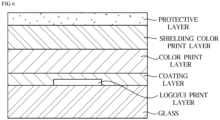
- FIG. 6 is a view showing a structure of a conventional door glass.
- a mother glass is cut, an edge thereof is processed, and then a heat strengthening process is performed therefor.
- a one-color printing (forming logo/UI print layer) for implementing the display configured to display a logo or a user interface is performed, and a coating layer is deposited using a material mixed with SiO 2 and Nb 2 O 5 , and then a two-color printing (forming a color print layer) for implementing a color of the door is performed.
- a three-color printing (forming a shielding color print layer and a protective layer) for securing a shielding force of the color print layer and securing the durability of the door is accompanied.
- FIG. 7 is a view showing a structure of a control panel according to one embodiment of the present invention.
- the control panel 210 may be composed of a glass 211, a coating layer 212 provided on an upper surface of the glass 211 while having a gap a first print layer 213 laminated in a shape corresponding to an upper surface of the coating layer 212, and a second print layer 214 laminated on an upper surface of the first print layer 213 and provided adjacent to the glass 211.
- the glass 211 may have a flat shape on which the coating layer 212 may be placed, and may be made of a transparent material having high visible light transmittance.
- the glass 211 may be made of a material having a visible light transmittance in a range of 80 to 100 % in order to satisfy a transmittance required as a material of an upper plate of the door 20.
- the glass 211 may be provided with a thickness of 2 to 6 mm in consideration of durability and purpose of use of the door 20.
- the coating layer 212 is a layer provided to secure the visibility and insulating property of the control panel 210, and in the present invention, the coating layer 212 is made of silicon nitride, silicon oxynitride, and a combination thereof which have excellent electrical resistance.
- Silicon nitride (SiN x ) and silicon oxynitride (SiNO x ) are insulating materials, and are inorganic materials having excellent mechanical properties, particularly, impact properties.
- AlSiN x , CrSiN x , TiSiN x , AlSiNO x , and the like may be used for silicon nitride and silicon oxynitride.
- the insulating ceramic material such as silicon nitride (SiN x ) or silicon oxynitride (SiNO x )
- SiN x silicon nitride
- SiNO x silicon oxynitride
- a resistance of the coating layer 212 increases. Accordingly, when 1,000 V is applied from an insulation tester, it is possible to secure the resistance of the coating layer to 500 M ⁇ or more.
- the content of silicon nitride (SiN x ) or silicon oxynitride (SiNO x ) of the coating layer 212 is limited to a range of 70 to 90 %.
- the coating layer 212 based on silicon nitride or silicon oxynitride may be doped or laminated with one or more selected from the group consisting of Al x O y , Nb x O y , and SiO x .
- the coating layer 212 may be doped or laminated with one or more selected from the group consisting of Si, Ni, Cr, Nb, Zr, Co, Ti, and Ag nanoparticles.
- the coating layer 212 may be limited to a thickness of 30 to 100 nm.
- the gap between the coating layers 212 may be appropriately adjusted in consideration of a color, a color difference value, reflectivity, transmittance, and the like of the door according to the embodiment, and provided by etching the coating layer 212 by introducing laser marking to be described below.
- the first print layer 213 is a layer provided to implement a basic color of the door 20, and may be provided in black, burgundy, pink, ivory, and gold colors.
- the color of the first print layer 213 is not limited thereto, and various colors of a high chroma series may be provided.
- the first print layer 213 formed on the upper surface of the coating layer 212 may be provided in a shape corresponding to the coating layer 212, and provided on a lower surface of the second print layer 214 adjacent to the glass 211.
- the second print layer 214 is a layer which implements a logo in which an image of a company or organization is formed by figures, characters, symbols, or combinations thereof in order to identify manufacturers of the clothing care apparatus 1.
- the second print layer 214 is a layer which implements a user interface including clothing treatment options, an operation time, a remaining time, and other menus.
- the second print layer 214 may be provided to be laminated on the upper surface of the first print layer 213 and adjacent to the glass 211.
- FIG. 7 shows that a shape of the second print layer 214 is a T-shape, but the shape of the second print layer 214 is not limited thereto and may be provided in various shapes in consideration of the logo and user interface described above as long as it is laminated on the upper surface of the first print layer 213 and adjacent to the glass 211 by being filled in the gap between the coating layer 212 and the first print layer 213.
- control panel 210 may further include a protective layer 215 formed on an upper surface of the second print layer 214.
- control panel 210 may include the protective layer 215 above the second print layer 214, that is, on the uppermost portion of the control panel 210.
- the protective layer 215 may contain one or more selected from the group consisting of metal oxide, metal nitride, metal oxynitride, and a combination thereof.
- a transmittance of light passing in a direction from the second print layer 214 toward the coating layer 212 may be 20 % or more, specifically, in a range of 20 to 70 %, and a reflectivity of light may be 70 % or less, specifically, in a range of 20 to 70 %.
- control panel 210 may be not only used as a mirror which may check the user's appearance but also implemented in various colors having high chroma by securing the reflectivity of the door 20 by introducing the gap between the coating layers 212.
- control panel 210 may solve the electrical conduction problem by introducing silicon nitride (SiN x ) and silicon oxynitride (SiNO x ), which are insulating materials, into the coating layer.
- SiN x silicon nitride
- SiNO x silicon oxynitride
- the resistance of the coating layer may be derived to 500 M ⁇ or more, thereby preventing the malfunction of the clothing care apparatus due to electrical conduction.
- an individual deposition method is used to form a coating layer functioning as a mirror after cutting a mother glass.
- the present invention has been intended to secure the visibility (a property of easily conspicuous shape or color) of the door 20 including the control panel 210 by introducing a method of forming a coating layer on a mother glass, forming a color layer after cutting and processing the coating layer, partially removing the coating layer/print layer by laser marking, and then reprinting.
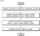
- FIG. 8 is a view showing a process of manufacturing the control panel according to one embodiment of the present invention.
- the method of manufacturing the clothing care apparatus includes forming a coating layer by applying one or more selected from the group consisting of SiN x or SiNO x and a combination thereof to a mother glass, laminating a color print layer after performing strengthening heat treatment for the formed coating layer, etching the coating layer and the color print layer with a fiber laser, and forming a logo/UI print layer so as to be adjacent to the glass and laminated on an upper surface of the color print layer.
- a control panel 210 adopts a method of forming a coating layer 212 on the entire surface of a mother glass 211 and then performing processing and printing, and thus is configured to minimize variation between final products and secure process efficiency.
- the coating layer 212 may be formed by coating an insulating material containing one or more selected from the group consisting of SiN x or SiNO x and a combination thereof on the mother glass 211.
- the coating layer 212 may be doped or laminated with one or more selected from the group consisting of Al x O y , Nb x O y , and SiO x .
- the coating layer 212 may be doped or laminated with one or more selected from the group consisting of Si, Ni, Cr, Nb, Zr, Co, Ti, and Ag nanoparticles.
- the method of forming the coating layer 212 on the mother glass 211 is not particularly limited thereto and may be performed by well-known methods in the art.
- the method may include a physical vapor deposition sputtering method (DC, RF, MF and reactive coating), a chemical vapor deposition (CVD) method, a thermal deposition method, an electron beam deposition method, and the like.
- a process of forming the coating layer 212 on the mother glass 211, then cutting the coating layer 212 to a required size, and processing an edge by introducing a computer numeric control (CNC) method may be performed.
- the heat treatment may be performed at a temperature of 650 to 700 °C.
- the heat treatment may be performed under a temperature condition of 650 °C or higher to improve the uniform strength of the laminated structure including the glass 211 and the coating layer 212.
- the temperature range of the strengthening heat treatment is limited to 700 °C or lower.
- the color print layer 213 is a layer provided to implement a basic color of a door 20, and may be provided in various colors such as black, burgundy, pink, ivory, and gold.
- an operation of forming the color print layer 213 and then etching the color print layer 213 with a fiber laser is introduced to secure the visibility of the door 20.
- the etching treatment may be performed to remove the coating layer 212 and the color print layer 213 with the fiber laser after forming the color print layer 213 and before forming a logo/UI print layer 214.
- the present invention has been intended to solve a poor smudging problem of the print layer and a print quality degradation problem due to damage to the glass, and secure surface quality of the door by controlling a frequency of the fiber laser to 50 to 100 Hz.
- the etching treatment process may be performed for 10 to 60 seconds in consideration of cost and productivity according to a process load.
- the logo/UI print layer 214 is formed to be adjacent to the glass 211 and laminated on an upper surface of the color print layer 213.
- the logo/UI print layer 214 is a layer provided to implement a logo or a user interface on the door 20, and may be provided ⁇ .
- the manufacturing method of the clothing care apparatus may further include forming a protective layer on an upper surface of the logo/UI print layer.
- the protective layer 215 may contain one or more selected from the group consisting of metal oxide, metal nitride, metal oxynitride, and a combination thereof.
- a coating layer was formed on a glass substrate through a series of processes such as cutting-CNC processing-strengthening heat treatment after depositing a coating material using SiN x and SiNO x series as a main component on the glass substrate by a PVD sputtering method. At this time, the strengthening heat treatment was performed at 665 °C for 10 minutes.
- color print layers having colors according to Tables 1 to 3 were formed through a one-color printing process.
- a laser marking process was performed under conditions of a speed of 1,700 m/s, a frequency of 70 Hz, and a power of 80 % to etch the coating layer and the color print layer, and then bond the logo/UI print layer to the glass together with the color print layer.
- the door 20 of the clothing care apparatus 1 was manufactured by laminating the uppermost protective layer.
- Comparative Example 1 is a case in which SiO 2 and Nb 2 O 5 are applied as a material of the coating layer, and it was found that the measured resistance was 0.5 M ⁇ when 1,000 V was applied from the insulation tester.
- control panel may provide the clothing care apparatus capable of interior color matching by not only solving the malfunction problem due to electrical conduction but also securing reflectivity and transmittance at the same time by applying silicon nitride or silicon oxynitride, which is the insulating material, as the material of the reflective layer.
- control panel according to the disclosed embodiment may adopt the method of forming the coating layer on the entire surface of the mother glass, and then performing processing and printing, thereby minimizing variation between the final products and securing process efficiency.
- a clothing care apparatus and a manufacturing method therefor According to a clothing care apparatus and a manufacturing method therefor according to one aspect, it is possible to provide a clothing care apparatus and a manufacturing method therefor which can not only secure the reflectivity and visibility of a door but also solve a malfunction problem due to electrical conduction.
Landscapes
- Engineering & Computer Science (AREA)
- Chemical & Material Sciences (AREA)
- Textile Engineering (AREA)
- Life Sciences & Earth Sciences (AREA)
- Chemical Kinetics & Catalysis (AREA)
- General Chemical & Material Sciences (AREA)
- Geochemistry & Mineralogy (AREA)
- Materials Engineering (AREA)
- Organic Chemistry (AREA)
- Accessory Of Washing/Drying Machine, Commercial Washing/Drying Machine, Other Washing/Drying Machine (AREA)
- Securing Of Glass Panes Or The Like (AREA)
- Detail Structures Of Washing Machines And Dryers (AREA)
Applications Claiming Priority (2)
| Application Number | Priority Date | Filing Date | Title |
|---|---|---|---|
| KR1020200061934A KR102899919B1 (ko) | 2020-05-22 | 2020-05-22 | 의류 관리기 및 그 제조방법 |
| PCT/KR2021/003337 WO2021235665A1 (fr) | 2020-05-22 | 2021-03-18 | Appareil d'entretien des vêtements et son procédé de fabrication |
Publications (2)
| Publication Number | Publication Date |
|---|---|
| EP4134478A1 true EP4134478A1 (fr) | 2023-02-15 |
| EP4134478A4 EP4134478A4 (fr) | 2023-10-25 |
Family
ID=78707932
Family Applications (1)
| Application Number | Title | Priority Date | Filing Date |
|---|---|---|---|
| EP21808278.2A Pending EP4134478A4 (fr) | 2020-05-22 | 2021-03-18 | Appareil d'entretien des vêtements et son procédé de fabrication |
Country Status (5)
| Country | Link |
|---|---|
| US (1) | US12421642B2 (fr) |
| EP (1) | EP4134478A4 (fr) |
| KR (1) | KR102899919B1 (fr) |
| CN (1) | CN115698415A (fr) |
| WO (1) | WO2021235665A1 (fr) |
Families Citing this family (8)
| Publication number | Priority date | Publication date | Assignee | Title |
|---|---|---|---|---|
| JP1687419S (fr) * | 2020-06-29 | 2021-06-07 | ||
| JP1732742S (ja) * | 2021-02-05 | 2022-12-20 | 衣類の洗浄・消臭用キャビネット | |
| JP1749895S (ja) * | 2021-03-03 | 2023-08-02 | 衣服用除湿脱臭及びしわ除去機 | |
| JP1749894S (ja) * | 2021-03-03 | 2023-08-02 | 衣服用除湿脱臭及びしわ除去機 | |
| USD1002975S1 (en) * | 2021-03-19 | 2023-10-24 | Guangzhou Shiyuan Electronic Technology Co., Ltd. | Clothes management apparatus |
| KR20240024689A (ko) * | 2022-08-17 | 2024-02-26 | 삼성전자주식회사 | 의류관리기 |
| USD1060894S1 (en) * | 2022-12-13 | 2025-02-04 | Samsung Electronics Co., Ltd. | Clothes care machine |
| USD1066832S1 (en) * | 2024-03-13 | 2025-03-11 | Samsung Electronics Co., Ltd. | Clothing care machine |
Family Cites Families (26)
| Publication number | Priority date | Publication date | Assignee | Title |
|---|---|---|---|---|
| GB9511841D0 (en) | 1995-06-10 | 1995-08-09 | Pilkington Glass Ltd | Mirrors and their production |
| US6745496B2 (en) * | 2001-03-20 | 2004-06-08 | Anthony Cassella | Air-flow dryer and method |
| US9274394B2 (en) * | 2007-03-05 | 2016-03-01 | Gentex Corporation | Multi-zone mirrors |
| KR101537616B1 (ko) * | 2009-07-22 | 2015-07-22 | 엘지전자 주식회사 | 냉장고 및 냉장고의 조작버튼패널의 제작방법 |
| US10000411B2 (en) | 2010-01-16 | 2018-06-19 | Cardinal Cg Company | Insulating glass unit transparent conductivity and low emissivity coating technology |
| US8834976B2 (en) | 2010-02-26 | 2014-09-16 | Guardian Industries Corp. | Articles including anticondensation and/or low-E coatings and/or methods of making the same |
| JP5549811B2 (ja) | 2010-07-15 | 2014-07-16 | ブラザー工業株式会社 | 携帯型プリンタ |
| JP2013242106A (ja) * | 2012-05-22 | 2013-12-05 | Hitachi Appliances Inc | Siを有する材料からコーティングされる冷蔵庫 |
| JP5771581B2 (ja) * | 2012-08-27 | 2015-09-02 | 日立アプライアンス株式会社 | 冷蔵庫 |
| JP6181210B2 (ja) * | 2013-02-20 | 2017-08-16 | サン−ゴバン グラス フランス | 熱放射反射コーティングを有する板ガラス |
| US9499438B2 (en) | 2013-02-28 | 2016-11-22 | Guardian Industries Corp. | Window for attenuating RF and IR electromagnetic signals |
| EP3047314B1 (fr) | 2013-09-18 | 2019-02-20 | Guardian Europe S.à.r.l. | Miroir diélectrique |
| US20150113825A1 (en) * | 2013-10-25 | 2015-04-30 | Richard Goulet | Drying cabinet for clothing and sports equipment |
| KR20150110068A (ko) * | 2014-03-24 | 2015-10-02 | 엘지전자 주식회사 | 디스플레이 장치 |
| FR3021414B1 (fr) * | 2014-05-21 | 2022-09-09 | Saint Gobain | Miroir colore |
| DE102014110437A1 (de) * | 2014-07-24 | 2016-01-28 | FREMACH GmbH | Bedienteil für elektrische oder elektronische Geräte |
| KR101513684B1 (ko) * | 2014-12-02 | 2015-04-21 | 주식회사 씨아이씨티 | 모바일 기기용 글라스의 인쇄층 형성방법 및 그 인쇄층 형성구조 |
| DE102014118497B4 (de) * | 2014-12-12 | 2017-06-29 | Schott Ag | Verfahren zur Herstellung eines Glaskeramikelements mit strukturierter Beschichtung, plattenförmig ausgebildetes Glaskeramikelement und Glaskeramik-Kochfeld |
| EP3031785B1 (fr) * | 2014-12-12 | 2018-10-17 | Schott AG | Procede de fabrication d'un element en vitroceramique faisant appel a un revetement structure |
| CN107541903B (zh) * | 2016-06-29 | 2020-04-24 | 青岛海尔洗衣机有限公司 | 一种用于家电的操作显示装置及洗衣机 |
| US10287724B2 (en) * | 2016-08-10 | 2019-05-14 | Whirlpool Corporation | Laundry treating appliance with a non-encapsulated glass lid |
| KR102075076B1 (ko) | 2017-02-22 | 2020-02-07 | (주)엘지하우시스 | 저투과 및 저반사 코팅유리 |
| US20210122671A1 (en) | 2017-07-31 | 2021-04-29 | Corning Incorporated | Hard anti-reflective coatings |
| KR102247653B1 (ko) | 2017-12-06 | 2021-04-30 | (주)엘지하우시스 | 무광 회색 코팅, 무광 회색 코팅 유리 및 복층 유리 |
| KR102568666B1 (ko) * | 2018-05-18 | 2023-08-22 | 엘지전자 주식회사 | 의류 처리 장치 |
| CN110730258B (zh) * | 2019-09-06 | 2021-05-04 | 华为技术有限公司 | 壳体结构、壳体制造方法及移动终端 |
-
2020
- 2020-05-22 KR KR1020200061934A patent/KR102899919B1/ko active Active
-
2021
- 2021-03-18 EP EP21808278.2A patent/EP4134478A4/fr active Pending
- 2021-03-18 WO PCT/KR2021/003337 patent/WO2021235665A1/fr not_active Ceased
- 2021-03-18 CN CN202180042925.0A patent/CN115698415A/zh active Pending
-
2022
- 2022-11-21 US US17/991,378 patent/US12421642B2/en active Active
Also Published As
| Publication number | Publication date |
|---|---|
| US12421642B2 (en) | 2025-09-23 |
| EP4134478A4 (fr) | 2023-10-25 |
| US20230090304A1 (en) | 2023-03-23 |
| WO2021235665A1 (fr) | 2021-11-25 |
| KR102899919B1 (ko) | 2025-12-16 |
| CN115698415A (zh) | 2023-02-03 |
| KR20210144487A (ko) | 2021-11-30 |
Similar Documents
| Publication | Publication Date | Title |
|---|---|---|
| EP4134478A1 (fr) | Appareil d'entretien des vêtements et son procédé de fabrication | |
| US6822208B2 (en) | Microwave door with viewing window | |
| US8202619B2 (en) | Coated article with sputter-deposited transparent conductive coating capable of surviving harsh environments, and method of making the same | |
| US7819113B2 (en) | Door assembly for a cooking apparatus | |
| US9388990B2 (en) | Metal panel, manufacturing method thereof and cooking device using the metal panel | |
| US20100088917A1 (en) | Clothes dryer and door thereof | |
| ITPN20060059A1 (it) | Forno di cottura con porta anti-condensa | |
| US20020014203A1 (en) | View port of a chemical vapor deposition device for manufacturing semiconductor devices | |
| EP1217875B1 (fr) | Bâti d'un four à micro-ondes | |
| WO2000029346A1 (fr) | Panneaux vitres | |
| CN101803489A (zh) | 导电性层叠体 | |
| Depla et al. | Smart textiles: an explorative study of the use of magnetron sputter deposition | |
| CZ20023552A3 (cs) | Průhledná deska obsahující kovové prvky a její použití | |
| US20040086652A1 (en) | Glazing panels | |
| WO2011021869A2 (fr) | Panneau de décoration et appareil domestique équipé de ce dernier | |
| KR100642839B1 (ko) | 인서트 몰드용 인쇄 필름 및 그의 제조방법 | |
| CN216849151U (zh) | 防眩光一体色盖板及屏幕 | |
| KR101694538B1 (ko) | 가전기기용 외장 패널 및 그 제조 방법 | |
| US20070210057A1 (en) | Domestic appliance, especially cooking appliance | |
| EP0548084A4 (en) | A vacuum deposited dark coating on a substrate | |
| EP3553385B1 (fr) | Appareil électroménager comprenant une paroi et procédé de production d'une paroi de l'appareil ménager ou d'un composant pour l'appareil ménager | |
| CN110484862A (zh) | 复合涂层Logo及其制备方法与包含其的陶瓷盖板和电子设备 | |
| KR20010071668A (ko) | 전기전도성 반사방지막이 부착된 유리 물품 및 이를사용한 음극선관 | |
| CN110484879B (zh) | 金属复合涂层Logo及其制备方法与包含其的陶瓷盖板和电子设备 | |
| US12546467B2 (en) | Doors for home appliance and appliance including the same having a panel edge portion with printed layers surrounding a window perimeter |
Legal Events
| Date | Code | Title | Description |
|---|---|---|---|
| STAA | Information on the status of an ep patent application or granted ep patent |
Free format text: STATUS: THE INTERNATIONAL PUBLICATION HAS BEEN MADE |
|
| PUAI | Public reference made under article 153(3) epc to a published international application that has entered the european phase |
Free format text: ORIGINAL CODE: 0009012 |
|
| STAA | Information on the status of an ep patent application or granted ep patent |
Free format text: STATUS: REQUEST FOR EXAMINATION WAS MADE |
|
| 17P | Request for examination filed |
Effective date: 20221111 |
|
| AK | Designated contracting states |
Kind code of ref document: A1 Designated state(s): AL AT BE BG CH CY CZ DE DK EE ES FI FR GB GR HR HU IE IS IT LI LT LU LV MC MK MT NL NO PL PT RO RS SE SI SK SM TR |
|
| DAV | Request for validation of the european patent (deleted) | ||
| DAX | Request for extension of the european patent (deleted) | ||
| A4 | Supplementary search report drawn up and despatched |
Effective date: 20230925 |
|
| RIC1 | Information provided on ipc code assigned before grant |
Ipc: C03C 17/00 20060101ALI20230919BHEP Ipc: C03C 17/34 20060101ALI20230919BHEP Ipc: D06F 34/30 20200101ALI20230919BHEP Ipc: D06F 34/34 20200101ALI20230919BHEP Ipc: D06F 34/32 20200101AFI20230919BHEP |
|
| STAA | Information on the status of an ep patent application or granted ep patent |
Free format text: STATUS: EXAMINATION IS IN PROGRESS |
|
| 17Q | First examination report despatched |
Effective date: 20250711 |