EP4134512A1 - Dispositif de compensation de volume - Google Patents
Dispositif de compensation de volume Download PDFInfo
- Publication number
- EP4134512A1 EP4134512A1 EP22185953.1A EP22185953A EP4134512A1 EP 4134512 A1 EP4134512 A1 EP 4134512A1 EP 22185953 A EP22185953 A EP 22185953A EP 4134512 A1 EP4134512 A1 EP 4134512A1
- Authority
- EP
- European Patent Office
- Prior art keywords
- oil
- chamber
- volume compensation
- heavy oil
- light oil
- Prior art date
- Legal status (The legal status is an assumption and is not a legal conclusion. Google has not performed a legal analysis and makes no representation as to the accuracy of the status listed.)
- Granted
Links
Images


Classifications
-
- E—FIXED CONSTRUCTIONS
- E21—EARTH OR ROCK DRILLING; MINING
- E21B—EARTH OR ROCK DRILLING; OBTAINING OIL, GAS, WATER, SOLUBLE OR MELTABLE MATERIALS OR A SLURRY OF MINERALS FROM WELLS
- E21B43/00—Methods or apparatus for obtaining oil, gas, water, soluble or meltable materials or a slurry of minerals from wells
- E21B43/12—Methods or apparatus for controlling the flow of the obtained fluid to or in wells
- E21B43/121—Lifting well fluids
- E21B43/128—Adaptation of pump systems with down-hole electric drives
-
- F—MECHANICAL ENGINEERING; LIGHTING; HEATING; WEAPONS; BLASTING
- F04—POSITIVE - DISPLACEMENT MACHINES FOR LIQUIDS; PUMPS FOR LIQUIDS OR ELASTIC FLUIDS
- F04B—POSITIVE-DISPLACEMENT MACHINES FOR LIQUIDS; PUMPS
- F04B47/00—Pumps or pumping installations specially adapted for raising fluids from great depths, e.g. well pumps
- F04B47/06—Pumps or pumping installations specially adapted for raising fluids from great depths, e.g. well pumps having motor-pump units situated at great depth
-
- F—MECHANICAL ENGINEERING; LIGHTING; HEATING; WEAPONS; BLASTING
- F04—POSITIVE - DISPLACEMENT MACHINES FOR LIQUIDS; PUMPS FOR LIQUIDS OR ELASTIC FLUIDS
- F04B—POSITIVE-DISPLACEMENT MACHINES FOR LIQUIDS; PUMPS
- F04B53/00—Component parts, details or accessories not provided for in, or of interest apart from, groups F04B1/00 - F04B23/00 or F04B39/00 - F04B47/00
- F04B53/18—Lubricating
Definitions
- the PCT/US2017/064498 therefore proposes a spring-loaded piston that slides relative to a pressurized gas chamber.
- the disadvantage here is that the compressibility of the gas limits the volume compensation, and the pressure in the gas would ensure a pressure increase in the working oil if the volume to be compensated for is large.
- a servomotor is provided, which moves the piston used for volume compensation, so that the working oil pressure cannot rise too much.
- This also requires pressure measurement and control.
- Such a system is complicated, expensive and prone to failure, especially because of the high temperatures.
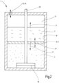
- the volume compensation device has a volume compensation chamber which is connected to the working oil chamber and has a light oil area for volume compensation of the light oil and a heavy oil area with a heavy oil or a fluid similar to heavy oil.
- the boundary between the light oil area and the heavy oil area can be moved and the heavy oil can flow into an expansion chamber that has another heavy oil area that adjoins a borehole fluid area, with the borehole fluid being able to flow in and out of the expansion chamber via an equalization opening.
- the idea of this alternative is that there are two chambers, one for the confluence of light and heavy oil and a separate one for the confluence of heavy oil and well water (or other well fluid lighter than heavy oil, e.g. petroleum).
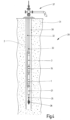
- the encapsulated volume compensating device 1 is used to provide volume compensation for a light oil 4 or a fluid similar to light oil used for lubrication in a working oil chamber 5 when it expands as a result of heating or contracts again when it cools down.
- the volume changes are due to three causes: Firstly, the temperature difference between the temperature when filling the light oil 4 and the temperature when the device 1 is introduced into the hot well water 6 of the borehole 2 . This temperature difference is approximately 80 to 150°C. Then, the electric motor 21 generates heat, causing a temperature difference of about 50°C. The axial bearing 19 then again contributes a temperature difference of approx. 30° C., but can lead to the highest temperature in its area. All of this takes place in an already hot environment, since geothermal energy is particularly effective when the hottest possible well water can be pumped.
- a heat exchanger 28 is provided, the function of which is to cool the light oil 4 .
- the heat exchanger 28 is arranged within the well wall 38 between the working oil chamber 5 and the well fluid 6 .
- a pump 29 is arranged, for example on the pump shaft 20. It drives an oil circuit 30 (small arrows), which supplies the oil to the heat exchanger 28. In this way, above all, the strong heat generated by the axial bearing 19 is dissipated and it is thereby avoided that the light oil 4 heats up too much and loses some of its lubricating properties.
- FIG 3 shows an alternative multi-chamber system in which the chambers are arranged differently.
- the working oil chamber 5 between the volume compensation chamber 10 and the expansion chamber 12.
- the axial bearing 19 and the electric motor 21 are arranged in the working oil chamber 5.
- the light oil 4 expands in the working oil chamber 5, it is pressed down through the connection 16 into the volume compensation chamber 10, in which the light oil area 10' and the heavy oil area 10" are located.
- a piston 9 is arranged here, which moves up and down in a cylinder 8 according to the change in volume of the light oil 4.
- the piston 9 can also be supported by a spring.
- the illustrated exemplary embodiments can of course vary, as can the exemplary embodiments according to FIG 2 and 3 be provided with a device to catch a leak or have a cooling device.
- the 3 could for example be arranged between the expansion chamber 12 and the working oil chamber 5, a device for catching a leak.
- Other variations, such as a system made up of two chambers, are also possible by transferring features from one example to the other.
Landscapes
- Engineering & Computer Science (AREA)
- Mechanical Engineering (AREA)
- General Engineering & Computer Science (AREA)
- Mining & Mineral Resources (AREA)
- Life Sciences & Earth Sciences (AREA)
- Geology (AREA)
- Fluid Mechanics (AREA)
- Environmental & Geological Engineering (AREA)
- Physics & Mathematics (AREA)
- General Life Sciences & Earth Sciences (AREA)
- Geochemistry & Mineralogy (AREA)
- Earth Drilling (AREA)
- Compressor (AREA)
Applications Claiming Priority (1)
| Application Number | Priority Date | Filing Date | Title |
|---|---|---|---|
| DE102021119889.5A DE102021119889A1 (de) | 2021-07-30 | 2021-07-30 | Volumenausgleichsvorrichtung |
Publications (3)
| Publication Number | Publication Date |
|---|---|
| EP4134512A1 true EP4134512A1 (fr) | 2023-02-15 |
| EP4134512C0 EP4134512C0 (fr) | 2024-12-11 |
| EP4134512B1 EP4134512B1 (fr) | 2024-12-11 |
Family
ID=82656264
Family Applications (1)
| Application Number | Title | Priority Date | Filing Date |
|---|---|---|---|
| EP22185953.1A Active EP4134512B1 (fr) | 2021-07-30 | 2022-07-20 | Dispositif de compensation de volume |
Country Status (2)
| Country | Link |
|---|---|
| EP (1) | EP4134512B1 (fr) |
| DE (1) | DE102021119889A1 (fr) |
Citations (5)
| Publication number | Priority date | Publication date | Assignee | Title |
|---|---|---|---|---|
| US1970484A (en) * | 1933-03-30 | 1934-08-14 | Reda Pump Company | Oil filled submergible electric motor |
| DE1186141B (de) | 1963-02-21 | 1965-01-28 | Klein Schanzlin & Becker Ag | Einrichtung zum Druckausgleich fuer fluessigkeitsgefuellte elektrische Unterwassermotoren |
| WO2016032521A1 (fr) | 2014-08-29 | 2016-03-03 | Ge Oil & Gas Esp, Inc. | Chambre de détente de fluide à soufflet protégé |
| WO2017096103A1 (fr) | 2015-12-04 | 2017-06-08 | General Electric Company | Ensemble à joint d'étanchéité pour système de pompage submersible et procédé associé |
| US20200095992A1 (en) * | 2018-09-20 | 2020-03-26 | Baker Hughes Oilfield Operations Llc | Isolated Chamber For Mechanical Face Seal Leakage In Submersible Well Pump Assembly |
Family Cites Families (7)
| Publication number | Priority date | Publication date | Assignee | Title |
|---|---|---|---|---|
| US3182214A (en) * | 1962-12-26 | 1965-05-04 | Borg Warner | Submersible motor seal section |
| US3502919A (en) * | 1969-01-02 | 1970-03-24 | Borg Warner | Submersible motor seal section |
| US3854064A (en) * | 1973-05-10 | 1974-12-10 | Trw Inc | Mechanical seal isolator |
| DE3120232C2 (de) | 1981-05-21 | 1985-03-21 | Klein, Schanzlin & Becker Ag, 6710 Frankenthal | Druckausgleichseinrichtung für den Elektromotor eines gekapselten Kreiselpumpen-Motor-Aggregates |
| US4462765A (en) * | 1981-12-04 | 1984-07-31 | Rodkin Valentin V | Liquid-proofing system for an electric motor of a deep-well pumping unit |
| US9763037B2 (en) | 2011-05-18 | 2017-09-12 | Medappit Llc | Network architecture for synchronized display |
| EP3555482B1 (fr) | 2016-12-16 | 2025-11-12 | Baker Hughes Holdings LLC | Compensateur de pression de lubrifiant de moteur électrique destiné à un moteur de pompe submersible |
-
2021
- 2021-07-30 DE DE102021119889.5A patent/DE102021119889A1/de active Pending
-
2022
- 2022-07-20 EP EP22185953.1A patent/EP4134512B1/fr active Active
Patent Citations (5)
| Publication number | Priority date | Publication date | Assignee | Title |
|---|---|---|---|---|
| US1970484A (en) * | 1933-03-30 | 1934-08-14 | Reda Pump Company | Oil filled submergible electric motor |
| DE1186141B (de) | 1963-02-21 | 1965-01-28 | Klein Schanzlin & Becker Ag | Einrichtung zum Druckausgleich fuer fluessigkeitsgefuellte elektrische Unterwassermotoren |
| WO2016032521A1 (fr) | 2014-08-29 | 2016-03-03 | Ge Oil & Gas Esp, Inc. | Chambre de détente de fluide à soufflet protégé |
| WO2017096103A1 (fr) | 2015-12-04 | 2017-06-08 | General Electric Company | Ensemble à joint d'étanchéité pour système de pompage submersible et procédé associé |
| US20200095992A1 (en) * | 2018-09-20 | 2020-03-26 | Baker Hughes Oilfield Operations Llc | Isolated Chamber For Mechanical Face Seal Leakage In Submersible Well Pump Assembly |
Also Published As
| Publication number | Publication date |
|---|---|
| DE102021119889A1 (de) | 2023-02-02 |
| EP4134512C0 (fr) | 2024-12-11 |
| EP4134512B1 (fr) | 2024-12-11 |
Similar Documents
| Publication | Publication Date | Title |
|---|---|---|
| DE10261079B4 (de) | Tauchpumpvorrichtung, magnetische Kopplung hierfür und Verfahren zum Pumpen | |
| DE102008018407B4 (de) | Unterwasserförderaggregat | |
| DE68928332T2 (de) | Verfahren und Vorrichtung zum hydraulischen und wahlweisen steuern von mindestens zwei Werkzeugen oder Instrumenten eines Gerätes, Ventil zur Durchführung dieses Verfahrens oder Benutzung dieses Geräts | |
| DE69833109T2 (de) | Unterwasser-pumpsystem und damit verbundenes verfahren | |
| DE68918937T2 (de) | Verfahren und vorrichtung zum ausgleich der bewegung in steigrohren. | |
| DE112016003093T5 (de) | Dichtungsabschnitt mit interner schmiermittelpumpe für eine elektrische tauchbohrlochpumpe | |
| DE102008012676A1 (de) | Drehdurchführung | |
| DE69817331T2 (de) | Aufblasbare bohrdichtung | |
| DE2230291A1 (de) | Pumpsystem | |
| DE102015112892A1 (de) | Verrohrung für eine Erdwärmesonde zur Gewinnung geothermischer Energie, insbesondere tiefengeothermischer Energie | |
| EP4134512B1 (fr) | Dispositif de compensation de volume | |
| EP2961921A1 (fr) | Dispositif de refoulement pour trou de forage | |
| DE102017118525A1 (de) | Hydraulisches steuersystem für ein getriebe | |
| DE68916765T2 (de) | Kolbenpumpvorrichtung für ein mehrphasiges fluid und anwendung dieser vorrichtung. | |
| EP2865894B1 (fr) | Dispositif de pompage submersible destiné à être utilisé dans un trou de forage | |
| DE102015009975B4 (de) | Hydrostirling-Maschine | |
| DE102013114320A1 (de) | Heißschlammpumpe | |
| DE102016213636A1 (de) | Außenzahnradpumpe für ein Abwärmerückgewinnungssystem | |
| DE69505653T2 (de) | Verfahren und vorrichtung zur förderung von fluiden aus ölbohrlöchern | |
| EP3701091A1 (fr) | Engin spécial de génie civil, notamment fraiseuse à rideau souterrain | |
| DE102013215468A1 (de) | Tauchlageranordnung und Verfahren zur Abdichtung derselben | |
| AT250178B (de) | Dichtungseinrichtung für die Welle eines Tauchkreiselpumpenaggregates | |
| DE102023132341A1 (de) | Tiefengeothermieanlage sowie Verfahren zum Herstellen einer Tiefengeothermieanlage | |
| EP3069023A1 (fr) | Pompe à boue chaude | |
| DE102014106520A1 (de) | Hochdruck-Plungerpumpe |
Legal Events
| Date | Code | Title | Description |
|---|---|---|---|
| PUAI | Public reference made under article 153(3) epc to a published international application that has entered the european phase |
Free format text: ORIGINAL CODE: 0009012 |
|
| STAA | Information on the status of an ep patent application or granted ep patent |
Free format text: STATUS: THE APPLICATION HAS BEEN PUBLISHED |
|
| AK | Designated contracting states |
Kind code of ref document: A1 Designated state(s): AL AT BE BG CH CY CZ DE DK EE ES FI FR GB GR HR HU IE IS IT LI LT LU LV MC MK MT NL NO PL PT RO RS SE SI SK SM TR |
|
| STAA | Information on the status of an ep patent application or granted ep patent |
Free format text: STATUS: REQUEST FOR EXAMINATION WAS MADE |
|
| 17P | Request for examination filed |
Effective date: 20230815 |
|
| RBV | Designated contracting states (corrected) |
Designated state(s): AL AT BE BG CH CY CZ DE DK EE ES FI FR GB GR HR HU IE IS IT LI LT LU LV MC MK MT NL NO PL PT RO RS SE SI SK SM TR |
|
| GRAP | Despatch of communication of intention to grant a patent |
Free format text: ORIGINAL CODE: EPIDOSNIGR1 |
|
| STAA | Information on the status of an ep patent application or granted ep patent |
Free format text: STATUS: GRANT OF PATENT IS INTENDED |
|
| INTG | Intention to grant announced |
Effective date: 20240425 |
|
| GRAJ | Information related to disapproval of communication of intention to grant by the applicant or resumption of examination proceedings by the epo deleted |
Free format text: ORIGINAL CODE: EPIDOSDIGR1 |
|
| STAA | Information on the status of an ep patent application or granted ep patent |
Free format text: STATUS: REQUEST FOR EXAMINATION WAS MADE |
|
| GRAP | Despatch of communication of intention to grant a patent |
Free format text: ORIGINAL CODE: EPIDOSNIGR1 |
|
| INTC | Intention to grant announced (deleted) | ||
| STAA | Information on the status of an ep patent application or granted ep patent |
Free format text: STATUS: GRANT OF PATENT IS INTENDED |
|
| INTG | Intention to grant announced |
Effective date: 20240704 |
|
| GRAS | Grant fee paid |
Free format text: ORIGINAL CODE: EPIDOSNIGR3 |
|
| GRAA | (expected) grant |
Free format text: ORIGINAL CODE: 0009210 |
|
| STAA | Information on the status of an ep patent application or granted ep patent |
Free format text: STATUS: THE PATENT HAS BEEN GRANTED |
|
| AK | Designated contracting states |
Kind code of ref document: B1 Designated state(s): AL AT BE BG CH CY CZ DE DK EE ES FI FR GB GR HR HU IE IS IT LI LT LU LV MC MK MT NL NO PL PT RO RS SE SI SK SM TR |
|
| REG | Reference to a national code |
Ref country code: GB Ref legal event code: FG4D Free format text: NOT ENGLISH |
|
| REG | Reference to a national code |
Ref country code: CH Ref legal event code: EP |
|
| REG | Reference to a national code |
Ref country code: IE Ref legal event code: FG4D Free format text: LANGUAGE OF EP DOCUMENT: GERMAN |
|
| REG | Reference to a national code |
Ref country code: DE Ref legal event code: R096 Ref document number: 502022002358 Country of ref document: DE |
|
| U01 | Request for unitary effect filed |
Effective date: 20250108 |
|
| U07 | Unitary effect registered |
Designated state(s): AT BE BG DE DK EE FI FR IT LT LU LV MT NL PT RO SE SI Effective date: 20250116 |
|
| PG25 | Lapsed in a contracting state [announced via postgrant information from national office to epo] |
Ref country code: HR Free format text: LAPSE BECAUSE OF FAILURE TO SUBMIT A TRANSLATION OF THE DESCRIPTION OR TO PAY THE FEE WITHIN THE PRESCRIBED TIME-LIMIT Effective date: 20241211 |
|
| PG25 | Lapsed in a contracting state [announced via postgrant information from national office to epo] |
Ref country code: ES Free format text: LAPSE BECAUSE OF FAILURE TO SUBMIT A TRANSLATION OF THE DESCRIPTION OR TO PAY THE FEE WITHIN THE PRESCRIBED TIME-LIMIT Effective date: 20241211 |
|
| PG25 | Lapsed in a contracting state [announced via postgrant information from national office to epo] |
Ref country code: NO Free format text: LAPSE BECAUSE OF FAILURE TO SUBMIT A TRANSLATION OF THE DESCRIPTION OR TO PAY THE FEE WITHIN THE PRESCRIBED TIME-LIMIT Effective date: 20250311 |
|
| PG25 | Lapsed in a contracting state [announced via postgrant information from national office to epo] |
Ref country code: GR Free format text: LAPSE BECAUSE OF FAILURE TO SUBMIT A TRANSLATION OF THE DESCRIPTION OR TO PAY THE FEE WITHIN THE PRESCRIBED TIME-LIMIT Effective date: 20250312 |
|
| PG25 | Lapsed in a contracting state [announced via postgrant information from national office to epo] |
Ref country code: RS Free format text: LAPSE BECAUSE OF FAILURE TO SUBMIT A TRANSLATION OF THE DESCRIPTION OR TO PAY THE FEE WITHIN THE PRESCRIBED TIME-LIMIT Effective date: 20250311 |
|
| PG25 | Lapsed in a contracting state [announced via postgrant information from national office to epo] |
Ref country code: SM Free format text: LAPSE BECAUSE OF FAILURE TO SUBMIT A TRANSLATION OF THE DESCRIPTION OR TO PAY THE FEE WITHIN THE PRESCRIBED TIME-LIMIT Effective date: 20241211 |
|
| PG25 | Lapsed in a contracting state [announced via postgrant information from national office to epo] |
Ref country code: PL Free format text: LAPSE BECAUSE OF FAILURE TO SUBMIT A TRANSLATION OF THE DESCRIPTION OR TO PAY THE FEE WITHIN THE PRESCRIBED TIME-LIMIT Effective date: 20241211 |
|
| PG25 | Lapsed in a contracting state [announced via postgrant information from national office to epo] |
Ref country code: IS Free format text: LAPSE BECAUSE OF FAILURE TO SUBMIT A TRANSLATION OF THE DESCRIPTION OR TO PAY THE FEE WITHIN THE PRESCRIBED TIME-LIMIT Effective date: 20250411 |
|
| PG25 | Lapsed in a contracting state [announced via postgrant information from national office to epo] |
Ref country code: SK Free format text: LAPSE BECAUSE OF FAILURE TO SUBMIT A TRANSLATION OF THE DESCRIPTION OR TO PAY THE FEE WITHIN THE PRESCRIBED TIME-LIMIT Effective date: 20241211 |
|
| PG25 | Lapsed in a contracting state [announced via postgrant information from national office to epo] |
Ref country code: CZ Free format text: LAPSE BECAUSE OF FAILURE TO SUBMIT A TRANSLATION OF THE DESCRIPTION OR TO PAY THE FEE WITHIN THE PRESCRIBED TIME-LIMIT Effective date: 20241211 |
|
| U20 | Renewal fee for the european patent with unitary effect paid |
Year of fee payment: 4 Effective date: 20250722 |
|
| PLBE | No opposition filed within time limit |
Free format text: ORIGINAL CODE: 0009261 |
|
| STAA | Information on the status of an ep patent application or granted ep patent |
Free format text: STATUS: NO OPPOSITION FILED WITHIN TIME LIMIT |
|
| REG | Reference to a national code |
Ref country code: CH Ref legal event code: L10 Free format text: ST27 STATUS EVENT CODE: U-0-0-L10-L00 (AS PROVIDED BY THE NATIONAL OFFICE) Effective date: 20251022 |
|
| 26N | No opposition filed |
Effective date: 20250912 |
|
| REG | Reference to a national code |
Ref country code: CH Ref legal event code: H13 Free format text: ST27 STATUS EVENT CODE: U-0-0-H10-H13 (AS PROVIDED BY THE NATIONAL OFFICE) Effective date: 20260224 |
|
| PG25 | Lapsed in a contracting state [announced via postgrant information from national office to epo] |
Ref country code: CH Free format text: LAPSE BECAUSE OF NON-PAYMENT OF DUE FEES Effective date: 20250731 |