EP4134535A1 - Steuerungsverfahren und steuerungsvorrichtung für einen verbrennungsmotor - Google Patents
Steuerungsverfahren und steuerungsvorrichtung für einen verbrennungsmotor Download PDFInfo
- Publication number
- EP4134535A1 EP4134535A1 EP20930169.6A EP20930169A EP4134535A1 EP 4134535 A1 EP4134535 A1 EP 4134535A1 EP 20930169 A EP20930169 A EP 20930169A EP 4134535 A1 EP4134535 A1 EP 4134535A1
- Authority
- EP
- European Patent Office
- Prior art keywords
- torque
- fuel cut
- internal combustion
- combustion engine
- control method
- Prior art date
- Legal status (The legal status is an assumption and is not a legal conclusion. Google has not performed a legal analysis and makes no representation as to the accuracy of the status listed.)
- Withdrawn
Links
- 238000002485 combustion reaction Methods 0.000 title claims abstract description 99
- 238000000034 method Methods 0.000 title claims description 17
- 239000000446 fuel Substances 0.000 claims abstract description 110
- 230000008929 regeneration Effects 0.000 claims abstract description 19
- 238000011069 regeneration method Methods 0.000 claims abstract description 19
- 230000005540 biological transmission Effects 0.000 claims description 23
- 230000004044 response Effects 0.000 claims description 12
- 230000003111 delayed effect Effects 0.000 claims description 9
- 230000007423 decrease Effects 0.000 claims description 3
- 238000002347 injection Methods 0.000 description 16
- 239000007924 injection Substances 0.000 description 16
- 239000003054 catalyst Substances 0.000 description 6
- 238000004880 explosion Methods 0.000 description 6
- 230000008859 change Effects 0.000 description 4
- 230000001934 delay Effects 0.000 description 4
- 238000011144 upstream manufacturing Methods 0.000 description 4
- 238000005259 measurement Methods 0.000 description 3
- 230000008569 process Effects 0.000 description 3
- 238000009825 accumulation Methods 0.000 description 2
- 239000000498 cooling water Substances 0.000 description 2
- 238000001514 detection method Methods 0.000 description 2
- 230000000541 pulsatile effect Effects 0.000 description 2
- 238000010926 purge Methods 0.000 description 2
- 239000000919 ceramic Substances 0.000 description 1
- 239000002826 coolant Substances 0.000 description 1
- 230000000694 effects Effects 0.000 description 1
- 230000006872 improvement Effects 0.000 description 1
- 238000005461 lubrication Methods 0.000 description 1
- 230000007246 mechanism Effects 0.000 description 1
- 230000002028 premature Effects 0.000 description 1
- 230000009467 reduction Effects 0.000 description 1
- 230000003252 repetitive effect Effects 0.000 description 1
- 239000000725 suspension Substances 0.000 description 1
Images
Classifications
-
- F—MECHANICAL ENGINEERING; LIGHTING; HEATING; WEAPONS; BLASTING
- F02—COMBUSTION ENGINES; HOT-GAS OR COMBUSTION-PRODUCT ENGINE PLANTS
- F02D—CONTROLLING COMBUSTION ENGINES
- F02D41/00—Electrical control of supply of combustible mixture or its constituents
- F02D41/02—Circuit arrangements for generating control signals
- F02D41/04—Introducing corrections for particular operating conditions
- F02D41/12—Introducing corrections for particular operating conditions for deceleration
- F02D41/123—Introducing corrections for particular operating conditions for deceleration the fuel injection being cut-off
-
- F—MECHANICAL ENGINEERING; LIGHTING; HEATING; WEAPONS; BLASTING
- F02—COMBUSTION ENGINES; HOT-GAS OR COMBUSTION-PRODUCT ENGINE PLANTS
- F02D—CONTROLLING COMBUSTION ENGINES
- F02D41/00—Electrical control of supply of combustible mixture or its constituents
- F02D41/008—Controlling each cylinder individually
- F02D41/0085—Balancing of cylinder outputs, e.g. speed, torque or air-fuel ratio
-
- F—MECHANICAL ENGINEERING; LIGHTING; HEATING; WEAPONS; BLASTING
- F02—COMBUSTION ENGINES; HOT-GAS OR COMBUSTION-PRODUCT ENGINE PLANTS
- F02D—CONTROLLING COMBUSTION ENGINES
- F02D41/00—Electrical control of supply of combustible mixture or its constituents
- F02D41/008—Controlling each cylinder individually
- F02D41/0087—Selective cylinder activation, i.e. partial cylinder operation
-
- F—MECHANICAL ENGINEERING; LIGHTING; HEATING; WEAPONS; BLASTING
- F02—COMBUSTION ENGINES; HOT-GAS OR COMBUSTION-PRODUCT ENGINE PLANTS
- F02D—CONTROLLING COMBUSTION ENGINES
- F02D41/00—Electrical control of supply of combustible mixture or its constituents
- F02D41/02—Circuit arrangements for generating control signals
- F02D41/021—Introducing corrections for particular conditions exterior to the engine
- F02D41/0215—Introducing corrections for particular conditions exterior to the engine in relation with elements of the transmission
- F02D41/0225—Introducing corrections for particular conditions exterior to the engine in relation with elements of the transmission in relation with the gear ratio or shift lever position
-
- F—MECHANICAL ENGINEERING; LIGHTING; HEATING; WEAPONS; BLASTING
- F02—COMBUSTION ENGINES; HOT-GAS OR COMBUSTION-PRODUCT ENGINE PLANTS
- F02D—CONTROLLING COMBUSTION ENGINES
- F02D41/00—Electrical control of supply of combustible mixture or its constituents
- F02D41/02—Circuit arrangements for generating control signals
- F02D41/021—Introducing corrections for particular conditions exterior to the engine
- F02D41/0235—Introducing corrections for particular conditions exterior to the engine in relation with the state of the exhaust gas treating apparatus
- F02D41/027—Introducing corrections for particular conditions exterior to the engine in relation with the state of the exhaust gas treating apparatus to purge or regenerate the exhaust gas treating apparatus
- F02D41/029—Introducing corrections for particular conditions exterior to the engine in relation with the state of the exhaust gas treating apparatus to purge or regenerate the exhaust gas treating apparatus the exhaust gas treating apparatus being a particulate filter
-
- F—MECHANICAL ENGINEERING; LIGHTING; HEATING; WEAPONS; BLASTING
- F02—COMBUSTION ENGINES; HOT-GAS OR COMBUSTION-PRODUCT ENGINE PLANTS
- F02D—CONTROLLING COMBUSTION ENGINES
- F02D41/00—Electrical control of supply of combustible mixture or its constituents
- F02D41/02—Circuit arrangements for generating control signals
- F02D41/14—Introducing closed-loop corrections
- F02D41/16—Introducing closed-loop corrections for idling
-
- F—MECHANICAL ENGINEERING; LIGHTING; HEATING; WEAPONS; BLASTING
- F02—COMBUSTION ENGINES; HOT-GAS OR COMBUSTION-PRODUCT ENGINE PLANTS
- F02D—CONTROLLING COMBUSTION ENGINES
- F02D41/00—Electrical control of supply of combustible mixture or its constituents
- F02D41/30—Controlling fuel injection
- F02D41/38—Controlling fuel injection of the high pressure type
- F02D41/40—Controlling fuel injection of the high pressure type with means for controlling injection timing or duration
- F02D41/401—Controlling injection timing
-
- F—MECHANICAL ENGINEERING; LIGHTING; HEATING; WEAPONS; BLASTING
- F02—COMBUSTION ENGINES; HOT-GAS OR COMBUSTION-PRODUCT ENGINE PLANTS
- F02D—CONTROLLING COMBUSTION ENGINES
- F02D2200/00—Input parameters for engine control
- F02D2200/02—Input parameters for engine control the parameters being related to the engine
- F02D2200/10—Parameters related to the engine output, e.g. engine torque or engine speed
- F02D2200/1002—Output torque
-
- F—MECHANICAL ENGINEERING; LIGHTING; HEATING; WEAPONS; BLASTING
- F02—COMBUSTION ENGINES; HOT-GAS OR COMBUSTION-PRODUCT ENGINE PLANTS
- F02D—CONTROLLING COMBUSTION ENGINES
- F02D2200/00—Input parameters for engine control
- F02D2200/02—Input parameters for engine control the parameters being related to the engine
- F02D2200/10—Parameters related to the engine output, e.g. engine torque or engine speed
- F02D2200/101—Engine speed
-
- F—MECHANICAL ENGINEERING; LIGHTING; HEATING; WEAPONS; BLASTING
- F02—COMBUSTION ENGINES; HOT-GAS OR COMBUSTION-PRODUCT ENGINE PLANTS
- F02D—CONTROLLING COMBUSTION ENGINES
- F02D2200/00—Input parameters for engine control
- F02D2200/60—Input parameters for engine control said parameters being related to the driver demands or status
- F02D2200/602—Pedal position
-
- F—MECHANICAL ENGINEERING; LIGHTING; HEATING; WEAPONS; BLASTING
- F02—COMBUSTION ENGINES; HOT-GAS OR COMBUSTION-PRODUCT ENGINE PLANTS
- F02D—CONTROLLING COMBUSTION ENGINES
- F02D2250/00—Engine control related to specific problems or objectives
- F02D2250/18—Control of the engine output torque
- F02D2250/21—Control of the engine output torque during a transition between engine operation modes or states
-
- F—MECHANICAL ENGINEERING; LIGHTING; HEATING; WEAPONS; BLASTING
- F02—COMBUSTION ENGINES; HOT-GAS OR COMBUSTION-PRODUCT ENGINE PLANTS
- F02D—CONTROLLING COMBUSTION ENGINES
- F02D2250/00—Engine control related to specific problems or objectives
- F02D2250/28—Control for reducing torsional vibrations, e.g. at acceleration
-
- F—MECHANICAL ENGINEERING; LIGHTING; HEATING; WEAPONS; BLASTING
- F02—COMBUSTION ENGINES; HOT-GAS OR COMBUSTION-PRODUCT ENGINE PLANTS
- F02D—CONTROLLING COMBUSTION ENGINES
- F02D41/00—Electrical control of supply of combustible mixture or its constituents
- F02D41/0025—Controlling engines characterised by use of non-liquid fuels, pluralities of fuels, or non-fuel substances added to the combustible mixtures
- F02D41/0047—Controlling exhaust gas recirculation [EGR]
- F02D41/005—Controlling exhaust gas recirculation [EGR] according to engine operating conditions
- F02D41/0055—Special engine operating conditions, e.g. for regeneration of exhaust gas treatment apparatus
-
- F—MECHANICAL ENGINEERING; LIGHTING; HEATING; WEAPONS; BLASTING
- F02—COMBUSTION ENGINES; HOT-GAS OR COMBUSTION-PRODUCT ENGINE PLANTS
- F02D—CONTROLLING COMBUSTION ENGINES
- F02D41/00—Electrical control of supply of combustible mixture or its constituents
- F02D41/02—Circuit arrangements for generating control signals
- F02D41/021—Introducing corrections for particular conditions exterior to the engine
- F02D41/0215—Introducing corrections for particular conditions exterior to the engine in relation with elements of the transmission
- F02D41/023—Introducing corrections for particular conditions exterior to the engine in relation with elements of the transmission in relation with the gear ratio shifting
Definitions
- the present invention relates to a control method and a control device for an internal combustion engine, which implements fuel cut in response to becoming zero of an accelerator opening degree during travel of a vehicle and thereafter generates an antiphase torque by supplying fuel to a cylinder in order to cancel out vibration of the vehicle caused due to the fuel cut.
- Fuel cut i.e. suspension of fuel supply
- Fuel cut is known to be implemented in accordance with a predetermined condition for permitting the fuel cut, in response to becoming zero of an accelerator opening degree during travel, for a purpose of reducing fuel consumption in an internal combustion engine for a vehicle.
- Patent Document 1 discloses an art for canceling out such vehicle vibration due to fuel cut by generating an antiphase torque by supplying fuel to some cylinders after the fuel cut.
- Patent Document 1 fails to take into account a magnitude of a level difference in torque of the internal combustion engine between before and after implementing the fuel cut.
- the internal combustion engine is at a relatively high level in torque generation even if the accelerator opening degree is set to zero by a driver, where the fuel cut is implemented under such state of the relatively high torque generation.
- a lag from a timing at which the accelerator opening degree becomes zero before the fuel cut until a timing at which a torque of a drive shaft in a drive system of the vehicle turns from positive to negative via zero is greater than a case that the internal combustion engine immediately before the fuel cut is at a low level in torque generation.
- the time lag in change of torque of the drive shaft is mainly ascribable to backlash in respective parts of the drive system.
- the vehicle vibration due to the fuel cut occurs after the torque of the drive shaft turns from positive to negative. Accordingly, the conventional art without consideration to the magnitude of torque generated by the internal combustion engine upon the fuel cut does not necessarily generate the antiphase torque at an appropriate timing. The antiphase torque generated at an inappropriate timing may rather aggravate the vehicle vibration.
- Patent Document 1 JP H08-177566 A
- a control method includes setting a timing of generating the antiphase torque to be later than that for normal operation, in response to implementation of fuel cut under high torque idle operation in which a torque of an internal combustion engine immediately before the fuel cut where accelerator opening degree is zero is higher than that in the normal operation.
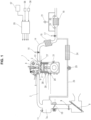
- FIG. 1 schematically illustrates system configurations of an internal combustion engine 1 according to the embodiment.
- Internal combustion engine 1 is, for example, a spark ignition type straight-three internal combustion engine, and includes a spark plug 4 at a center of a combustion chamber surrounded by an intake valve 2 and an exhaust valve 3, wherein intake valve 2 is accompanied by a variable valve timing mechanism not shown.
- Internal combustion engine 1 further includes an intake port 6 in which a fuel injection valve 5 structured to inject fuel toward intake valve 2 is disposed.
- internal combustion engine 1 may be a cylinder direct injection type internal combustion engine structured to inject fuel directly into cylinders.
- Intake port 6 is connected to an intake passage 7 including an intake collector 7a. Upstream with respect to intake collector 7a, intake passage 7 further includes an air cleaner 8, an air flow meter 9, and an electronically-controlled throttle valve 10 which are arranged in this order from the upstream side. Intake collector 7a includes a T-MAP sensor 11 structured to measure a pressure and an intake air temperature inside the intake collector 7a.
- Exhaust port 13 is connected to an exhaust passage 14 including a catalyst unit 15 composed of a three-way catalyst.
- Exhaust passage 14 further includes: an air-fuel ratio sensor 16 disposed upstream with respect to catalyst unit 15; an O2 sensor 17 disposed downstream with respect to catalyst unit 15; and an exhaust particulate filter 18 (i.e., a GPF 18) disposed downstream with respect to O2 sensor 17 and structured to collect exhaust particulates in exhaust gas.
- GPF 18 is composed of a sealed type ceramic monolithic filter coated with a three-way catalyst.
- catalyst unit 15 of the upstream side is disposed inside an engine room of a vehicle, while GPF 18 is disposed beneath a floor of the vehicle.
- GPF 18 is provided with temperature sensors 19 and 20 respectively disposed at an inlet and an outlet of GPF 18. Furthermore, GPF 18 is provided with a differential pressure sensor 21 structured to respond to a difference in pressure between the inlet and the outlet of GPF 18, in order to measure a pressure loss (i.e., monitor a state of particulate accumulation).
- Exhaust gas recirculation passage 23 includes an EGR gas cooler 24 and an EGR valve 25.
- Internal combustion engine 1 includes various sensors such as a cooling water temperature sensor 27, an oil temperature sensor 28 and an oil pressure sensor 29 for lubrication oil, a knocking sensor 30, and a crank angle sensor 31 for measurement of an engine speed.
- sensors such as a cooling water temperature sensor 27, an oil temperature sensor 28 and an oil pressure sensor 29 for lubrication oil, a knocking sensor 30, and a crank angle sensor 31 for measurement of an engine speed.
- engine controller 35 receives various signals such as: a measurement signal from an accelerator opening sensor 36 that measures a depression amount of an accelerator pedal operated by a driver; a signal corresponding to a gear ratio of a transmission which is outputted from a transmission controller 37; and a vehicle speed signal from a vehicle speed sensor 38. Furthermore, engine controller 35 receives signals corresponding to an electric current in an alternator and a coolant pressure in an air conditioner, in order to calculate engine loads required for driving the alternator not shown and a compressor for the air conditioner not shown which are auxiliaries driven by internal combustion engine 1.
- engine controller 35 Based on these signals, engine controller 35 performs overall control on internal combustion engine 1. For example, engine controller 35 optimally controls a fuel injection amount and a fuel injection timing of fuel injection valve 5 in each cylinder, an ignition timing of spark plug 4, and an accelerator opening degree of throttle valve 10.
- Engine controller 35 is configured to implement forcible regeneration of GPF 18 in response to detection of a particulate accumulation state above a predetermined level (i.e., detection of a so-called clogged state) by differential pressure sensor 21, while also considering other conditions including a temperature of GPF 18.
- the exhaust particulates that have accumulated are burned and removed by: increasing the accelerator opening degree of throttle valve 10 and thereby increasing amounts of intake air and fuel; and delaying the ignition timing and thereby heightening an exhaust gas temperature.
- the forcible regeneration of GPF 18 is implemented in case that GPF 18 is low in temperature due to continuous low load operation etc., because in general GPF 18 is spontaneously regenerated in case that GPF 18 is high in temperature due to high load operation etc.
- the forcible regeneration of GPF 18 is implemented when the accelerator opening degree is zero, i.e., when the accelerator pedal is released by a driver.
- the transmission may be any one of a stepped or continuously variable automatic transmission or a manual transmission.
- the transmission is a belt type continuously variable transmission (CVT) that has a transmission ratio continuously controlled by transmission controller 37 with reference to the accelerator opening degree and the vehicle speed mainly.
- the transmission includes an input shaft connected to an output shaft (i.e., a crank shaft) of internal combustion engine 1 via a torque converter not shown, and includes an output shaft structured to drive driving wheels of the vehicle via a final reduction gear and a drive shaft.
- Internal combustion engine 1 implements fuel cut during coasting travel performed due to release of the accelerator pedal by a driver during vehicle travel, for purposes such as improvement of fuel efficiency and achievement of so-called engine brake effect.
- internal combustion engine 1 implements a process for generating an antiphase torque by injecting fuel in a cylinder (i.e., by utilizing combustion in the cylinder), in order to cancel out frontward and rearward vibration of the vehicle due to torsional vibration caused by the fuel cut.
- the frontward and rearward vibration of the vehicle due to the torsional vibration can be effectively suppressed by applying the antiphase torque at a phase delayed for a quarter cycle of the torsional vibration.
- This timing of applying the antiphase torque is set depending on a torque of internal combustion engine 1 immediately before the fuel cut, and is further delayed in case that the torque of internal combustion engine 1 immediately before the fuel cut is high.
- the antiphase torque is generated with use of a combustion cylinder that is determined to be a cylinder nearest to a desired timing in original ignition timing according to ignition order. Then, cylinders prior to the combustion cylinder in the ignition order is determined to be non-combustion cylinders.
- the antiphase torque is generated at a magnitude that increases with increase in torque of internal combustion engine 1 immediately before the fuel cut. In other words, the increase in torque of internal combustion engine 1 immediately before the fuel cut increases an amount of fuel injection to the combustion cylinder for generating the antiphase torque.
- internal combustion engine 1 implements fuel injection and ignition also in a second combustion cylinder that is a cylinder subsequent to a first combustion cylinder in the ignition order.
- the torsional vibration has a frequency affected by the gear ratio of the transmission and by the engine speed of internal combustion engine 1.
- the lower the gear ratio of the transmission is i.e., the lower speed gear the transmission is at
- the lower the frequency of the torsional vibration is, and the more the timing late by the quarter cycle of the torsional vibration is delayed.
- the higher the engine speed of internal combustion engine 1 is, the higher the frequency of the torsional vibration is, and the more the timing late by the quarter cycle of the torsional vibration is advanced.
- internal combustion engine 1 selects the combustion cylinder(s), which is/are employed for generating the antiphase torque after the fuel cut, and the non-combustion cylinders, in view of the torque of internal combustion engine 1 immediately before the fuel cut, the gear ratio upon implementing the fuel cut, and the engine speed of internal combustion engine 1 upon implementing the fuel cut.
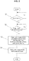
- FIG. 2 is a flow chart of processes for the fuel cut control executed by engine controller 35.
- Step 1 is repetitive determination of whether an idle switch flag is ON.
- the idle switch flag is a flag for representing being zero of the accelerator opening degree, and is turned ON (i.e., has a value of "1") in response to determination that the accelerator pedal is fully closed, wherein the determination is made in response to satisfaction of a condition that the output signal from accelerator opening sensor 36 corresponding to the depression of the accelerator pedal continues to be lower than a predetermined level for a predetermined time period that is relatively short.
- step 2 is executed to determine whether to permit the fuel cut. Specifically, this is determination of whether some conditions for permitting the fuel cut other than the accelerator opening degree are satisfied.
- the permission conditions for the fuel cut include: a condition that the cooling water temperature is equal to or greater than a predetermined temperature; a condition that the engine speed of internal combustion engine 1 is equal to or greater than a predetermined engine speed; and a condition that the vehicle speed is equal to or greater than a predetermined vehicle speed.
- step 3 is executed to select the combustion cylinder(s) and the non-combustion cylinders for operation immediately after implementing the fuel cut, depending on the torque of internal combustion engine 1 (which corresponds to the torque of internal combustion engine 1 immediately before the fuel cut), the engine speed of internal combustion engine 1, and the gear ratio of the transmission at that moment.
- step 4 is executed to control fuel injection for each cylinder in accordance with the selection in step 3. Accordingly, step 4 includes implementation of the fuel cut.
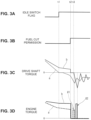
- FIGs. 3A to 3D are time charts showing change in torque of the drive shaft ( FIG. 3C ) and torque of internal combustion engine 1 ( FIG. 3D ) upon the fuel cut, and are illustrative views drawn schematically for facilitation of understanding.
- the following exemplifies a case that the forcible regeneration of GPF 18 is in operation and a case that the forcible regeneration of GPF 18 is not in operation, wherein the latter case corresponds to normal operation.
- the forcible regeneration of GPF 18 is a factor that increases the torque of internal combustion engine 1 immediately before the fuel cut.
- Each of broken lines (a) shows change in torque before and after the fuel cut, in case of the normal operation, i.e., in case that the forcible regeneration of GPF 18 is not in operation.
- the idle switch flag shown in FIG. 3A becomes ON, i.e., the accelerator opening degree becomes zero.
- the fuel cut is implemented (see a fuel cut permission flag in FIG. 3B ).
- throttle valve 10 is substantially fully closed at time instant t1, and accordingly the torque of internal combustion engine 1 sufficiently decreases by time instant t2.
- the torque of the drive shaft becomes zero instantly at time instant t1 at which the accelerator opening degree becomes zero, and in many cases turns negative by time instant t2 at which the fuel cut is implemented.
- the backlash in the transmission and the drive system are absorbed before the fuel cut, and the transmission and the drive system are directly affected by a level difference in torque of internal combustion engine 1 which is generated due to the fuel cut.
- the antiphase torque is desired to be generated at a timing that is delayed for the quarter cycle of the torsional vibration from time instant t2 as a starting point.
- the drawing shows an example of selecting a cylinder #1 as a combustion cylinder having an explosion stroke near to the timing desirable for generating the antiphase torque, in order to implement explosion and combustion in cylinder #1. This serves to suppress the frontward and rearward vibration of the vehicle (shown as fluctuation in torque of the drive shaft in FIG. 3C ) due to the torsional vibration.
- reference sign #1 in FIG. 3D schematically indicates an injection pulse in cylinder #1.
- the explosion and combustion in cylinder #1 similarly raises the torque of internal combustion engine 1 in a pulsatile form, although not detailed in FIG. 3D .
- the normal operation may be defined as a case that the torque of the drive shaft turns from positive to negative within a time period from the becoming zero of the accelerator opening degree until the implementation of the fuel cut.
- Each of broken lines (b) shows behavior in case that the forcible regeneration of GPF 18 is in operation.
- the torque of internal combustion engine 1 is higher than the case of broken lines (a) during vehicle traveling, and is relatively high also after the accelerator opening degree becomes zero at time instant t1. This is because the forcible regeneration of GPF 18 requires an extra torque, i.e. extra amounts of intake air and fuel, in addition to a torque required for idle operation. Even after the accelerator opening degree is set to zero by a driver, the forcible regeneration of GPF 18 is continued, and throttle valve 10 is not fully closed but is maintained open at a certain degree. This raises the torque of internal combustion engine 1.
- high torque idle operation such idle operation with the torque of internal combustion engine 1 higher than that for the normal operation is referred to as "high torque idle operation", for convenience.
- loads due to the auxiliaries such as the compressor for the air conditioner and the alternator for generation are high; an inflow of purge gas from a canister is large; and/or the torque of internal combustion engine 1 is increased in compensation for a large loss due to friction etc.
- the torque of internal combustion engine 1 at the timing at which the accelerator opening degree is set to zero is further increased.
- the torque of internal combustion engine 1 stays relatively high even after the becoming zero of the accelerator opening degree at time instant t1, and is at a high level at time instant t2 at which the fuel cut is implemented.
- the implementation of the fuel cut drops the torque of internal combustion engine 1 to zero, in which the level difference in torque between before and after the fuel cut is greater than that in the normal operation shown by broken line (a).
- the torque of the drive shaft decreases slowly because of a relatively high positive torque exerted on the transmission from internal combustion engine 1 even during a period between time instants t1 and t2.
- the torque of the drive shaft becomes zero in response to implementation of the fuel cut at time instant t2, and turns negative at a time instant t3.
- the time period between time instants t2 and t3 corresponds to a time lag due to the backlash in respective parts of the drive system.
- the frontward and rearward vibration of the vehicle due to the torsional vibration occurs from a starting point that is time instant t3 at which the torque of the drive shaft turns negative.
- the antiphase torque is generated at a timing delayed for the quarter cycle of the torsional vibration from time instant t2 as a starting point similarly to the case of the normal operation shown by broken line (a), the antiphase torque at such timing is premature and may not only fail to appropriately suppress the frontward and rearward vibration of the vehicle, but also rather deteriorate the vibration.
- the fuel cut control according to the present embodiment is configured to set the timing of generating the antiphase torque to be later than that for the normal operation in view of the time lag from time instant t2 to t3, in case that the torque of internal combustion engine 1 immediately before the fuel cut is high.
- the drawing shows an example in which a cylinder #2 subsequent to cylinder #1 in the ignition order is selected as a combustion cylinder having an explosion stroke near to the timing desirable for generating the antiphase torque (i.e., a timing delayed for the quarter cycle of the torsional vibration from time instant t3 as a starting point). This means avoiding fuel injection in cylinder #1 determined as a non-combustion cylinder, and implementing fuel injection and ignition in the subsequent one, cylinder #2.
- reference sign #2 in FIG. 3D schematically indicates an injection pulse in cylinder #2.
- the explosion and combustion in cylinder #2 similarly raises the torque of internal combustion engine 1 in a pulsatile form, although not detailed in FIG. 3D .
- Each of pulse waveforms labelled with reference signs #1 and #2 has a height corresponding to an amount of fuel injection or a magnitude of torque generation in a cylinder.
- the amount of fuel injection in the combustion cylinder for generating the antiphase torque is increased in comparison with the normal operation.
- the antiphase torque is increased corresponding to a magnitude of the level deference in torque of internal combustion engine 1 caused by the fuel cut.
- the increase in antiphase torque serves to effectively suppress the torsional vibration, because the torsional vibration increases in amplitude with increase in torque level difference caused by the fuel cut.
- the frequency of the torsional vibration is affected by the gear ratio of the transmission and by the engine speed of internal combustion engine 1.
- the lower the gear ratio of the transmission is i.e., the lower speed gear the transmission is at
- the combustion cylinder is optimally selected.
- cylinders #1 and #2 are determined as the non-combustion cylinders, and the subsequent one, a cylinder #3, is selected as the combustion cylinder in which fuel injection and ignition are implemented.
- the antiphase torque is required to be further increased, i.e., in case that combustion with use of one cylinder is insufficient for generating a required antiphase torque, it is allowed to implement combustion and explosion in a plurality of cylinders.
- the torque of internal combustion engine 1 immediately before the fuel cut can be appropriately calculated from the amount of intake air, the engine speed of internal combustion engine 1, the pressure inside the intake collector 7a, the opening degree of throttle valve 10, the amount of fuel injection, the ignition timing, a flow rate of EGR gas, a flow rate of purge gas, a torque loss inside the internal combustion engine 1, etc.
- the torque level difference due to the fuel cut may be calculated as a total sum of negative torques non-contributory to vehicle travel, such as drive torques of the auxiliaries including the compressor for air conditioner and the alternator, friction torques of the drive system including the transmission, amounts of air and fuel required for the regeneration of GPF 18.
- the antiphase torque is generated basically at the timing determined depending on the magnitude of the torque of internal combustion engine 1 immediately before the fuel cut.
- the basic timing for generating the antiphase torque may be determined depending on presence or absence of a factor(s) predetermined as a representative factor(s), such as the forcible regeneration of GPF 18, that causes the torque of internal combustion engine 1 immediately before the fuel cut to be greater than the normal operation. This means setting the timing of the antiphase torque later than the normal operation, in response to the high torque idle operation such as the regeneration of GPF 18, without calculating an actual torque of internal combustion engine 1.
Landscapes
- Engineering & Computer Science (AREA)
- Chemical & Material Sciences (AREA)
- Combustion & Propulsion (AREA)
- Mechanical Engineering (AREA)
- General Engineering & Computer Science (AREA)
- Electrical Control Of Air Or Fuel Supplied To Internal-Combustion Engine (AREA)
- Combined Controls Of Internal Combustion Engines (AREA)
Applications Claiming Priority (1)
| Application Number | Priority Date | Filing Date | Title |
|---|---|---|---|
| PCT/JP2020/015821 WO2021205566A1 (ja) | 2020-04-08 | 2020-04-08 | 内燃機関の制御方法および制御装置 |
Publications (2)
| Publication Number | Publication Date |
|---|---|
| EP4134535A1 true EP4134535A1 (de) | 2023-02-15 |
| EP4134535A4 EP4134535A4 (de) | 2023-05-31 |
Family
ID=78023912
Family Applications (1)
| Application Number | Title | Priority Date | Filing Date |
|---|---|---|---|
| EP20930169.6A Withdrawn EP4134535A4 (de) | 2020-04-08 | 2020-04-08 | Steuerungsverfahren und steuerungsvorrichtung für einen verbrennungsmotor |
Country Status (5)
| Country | Link |
|---|---|
| US (1) | US12092045B2 (de) |
| EP (1) | EP4134535A4 (de) |
| JP (1) | JP7235167B2 (de) |
| CN (1) | CN114174657B (de) |
| WO (1) | WO2021205566A1 (de) |
Families Citing this family (1)
| Publication number | Priority date | Publication date | Assignee | Title |
|---|---|---|---|---|
| CN116066217B (zh) * | 2023-03-03 | 2025-07-18 | 潍柴动力股份有限公司 | 一种车辆尾气的颗粒控制方法及相关装置 |
Family Cites Families (19)
| Publication number | Priority date | Publication date | Assignee | Title |
|---|---|---|---|---|
| JPH08177566A (ja) | 1994-12-20 | 1996-07-09 | Nissan Motor Co Ltd | エンジンのトルク制御装置 |
| SE512556C2 (sv) * | 1995-12-22 | 2000-04-03 | Volvo Ab | Metod för reducering av vibrationer i ett fordon och anordning för utförande av metoden |
| JP2002322931A (ja) | 2001-04-25 | 2002-11-08 | Fuji Heavy Ind Ltd | エンジンの燃料噴射制御装置 |
| JP2002364406A (ja) | 2001-06-08 | 2002-12-18 | Denso Corp | 内燃機関の自動停止装置 |
| ITBO20030213A1 (it) * | 2003-04-11 | 2004-10-12 | Magneti Marelli Powertrain Spa | Metodo per il controllo del regime di un motore |
| JP2006057527A (ja) * | 2004-08-19 | 2006-03-02 | Denso Corp | 電子スロットル制御装置 |
| JP2008075689A (ja) * | 2006-09-19 | 2008-04-03 | Nissan Motor Co Ltd | 無段変速機の変速制御装置 |
| JP5077057B2 (ja) * | 2007-08-04 | 2012-11-21 | 日産自動車株式会社 | エンジンの燃料噴射制御装置 |
| US7980066B2 (en) * | 2007-12-19 | 2011-07-19 | Detroit Diesel Corporation | Thermal management for an internal combustion engine to optimize diesel particulate filter regeneration events |
| US8386150B2 (en) * | 2010-04-28 | 2013-02-26 | GM Global Technology Operations LLC | Fuel cutoff transition control systems and methods |
| US9587572B2 (en) * | 2014-03-05 | 2017-03-07 | Cummins Inc. | Systems and methods to reduce torsional conditions in an internal combustion engine |
| FR3035843B1 (fr) * | 2015-05-04 | 2017-05-19 | Peugeot Citroen Automobiles Sa | Procede de gestion des pentes de l’agrement preventif en deceleration |
| WO2016194068A1 (ja) * | 2015-05-29 | 2016-12-08 | 日産自動車株式会社 | 車両用内燃機関の制御装置 |
| CN109790786B (zh) * | 2016-09-16 | 2020-04-14 | 日产自动车株式会社 | 车辆用发动机的控制方法以及控制装置 |
| JP7123302B2 (ja) * | 2018-05-30 | 2022-08-23 | マツダ株式会社 | 車両の制御装置 |
| JP7020337B2 (ja) * | 2018-08-07 | 2022-02-16 | トヨタ自動車株式会社 | 内燃機関の制御装置 |
| KR102703733B1 (ko) * | 2018-11-23 | 2024-09-06 | 현대자동차주식회사 | 엔진 진동 저감을 위한 모터제어장치 및 방법 |
| JP7047731B2 (ja) * | 2018-12-04 | 2022-04-05 | トヨタ自動車株式会社 | 内燃機関システム |
| JP7327346B2 (ja) * | 2020-10-16 | 2023-08-16 | トヨタ自動車株式会社 | 内燃機関の制御装置 |
-
2020
- 2020-04-08 US US17/632,037 patent/US12092045B2/en active Active
- 2020-04-08 CN CN202080053608.4A patent/CN114174657B/zh active Active
- 2020-04-08 EP EP20930169.6A patent/EP4134535A4/de not_active Withdrawn
- 2020-04-08 WO PCT/JP2020/015821 patent/WO2021205566A1/ja not_active Ceased
- 2020-04-08 JP JP2022513768A patent/JP7235167B2/ja active Active
Also Published As
| Publication number | Publication date |
|---|---|
| CN114174657A (zh) | 2022-03-11 |
| CN114174657B (zh) | 2023-06-13 |
| EP4134535A4 (de) | 2023-05-31 |
| US12092045B2 (en) | 2024-09-17 |
| WO2021205566A1 (ja) | 2021-10-14 |
| JPWO2021205566A1 (de) | 2021-10-14 |
| US20230032697A1 (en) | 2023-02-02 |
| JP7235167B2 (ja) | 2023-03-08 |
Similar Documents
| Publication | Publication Date | Title |
|---|---|---|
| CN103502600B (zh) | 运行配备气动增压系统的车辆的方法 | |
| CN103003548B (zh) | 车辆气动增压器系统的操作方法和设备 | |
| CN103502601A (zh) | 运行配备气动增压系统的车辆的方法 | |
| CN103477047A (zh) | 运行配备气动增压系统的车辆的方法 | |
| US8528323B2 (en) | System and method for particulate matter filter regeneration using a catalytic converter as a combustor | |
| US12025072B2 (en) | Control method and control device for internal combustion engine for vehicle | |
| EP1279813A2 (de) | Vorrichtung und Verfahren zur Regelung von Kraftfahrzeugen | |
| US12092045B2 (en) | Control method and control device for internal combustion engine | |
| US6263856B1 (en) | Powertrain output monitor | |
| US20240141858A1 (en) | Vehicle | |
| US20220003181A1 (en) | Internal combustion engine control apparatus | |
| US12459490B2 (en) | Hybrid electric vehicle | |
| US11808223B2 (en) | Method and a control system for controlling an internal combustion engine | |
| JP2006161561A (ja) | 内燃機関の燃料噴射制御装置 | |
| US11927166B2 (en) | Control method and control device for internal combustion engine | |
| JP7786335B2 (ja) | 車両の制御装置 | |
| US12473868B2 (en) | Vehicle | |
| US20250162567A1 (en) | Vehicle | |
| JP2026051788A (ja) | 車両の制御装置 | |
| JP2008273423A (ja) | 車両の触媒昇温制御装置及び触媒昇温制御方法 | |
| JP2026037676A (ja) | ハイブリッド車両 | |
| JP2025121770A (ja) | 車両用制御装置 | |
| US20020179068A1 (en) | Method of operating an internal -combustion engine | |
| JP2026049368A (ja) | ハイブリッド車両 | |
| JPH08277729A (ja) | 内燃機関のバルブタイミング制御装置 |
Legal Events
| Date | Code | Title | Description |
|---|---|---|---|
| STAA | Information on the status of an ep patent application or granted ep patent |
Free format text: STATUS: THE INTERNATIONAL PUBLICATION HAS BEEN MADE |
|
| PUAI | Public reference made under article 153(3) epc to a published international application that has entered the european phase |
Free format text: ORIGINAL CODE: 0009012 |
|
| STAA | Information on the status of an ep patent application or granted ep patent |
Free format text: STATUS: REQUEST FOR EXAMINATION WAS MADE |
|
| 17P | Request for examination filed |
Effective date: 20220124 |
|
| AK | Designated contracting states |
Kind code of ref document: A1 Designated state(s): AL AT BE BG CH CY CZ DE DK EE ES FI FR GB GR HR HU IE IS IT LI LT LU LV MC MK MT NL NO PL PT RO RS SE SI SK SM TR |
|
| REG | Reference to a national code |
Ref country code: DE Ref legal event code: R079 Free format text: PREVIOUS MAIN CLASS: F02D0041340000 Ipc: F02D0041120000 |
|
| A4 | Supplementary search report drawn up and despatched |
Effective date: 20230503 |
|
| RIC1 | Information provided on ipc code assigned before grant |
Ipc: B60W 30/20 20060101ALI20230425BHEP Ipc: F02D 41/02 20060101ALI20230425BHEP Ipc: F02D 41/12 20060101AFI20230425BHEP |
|
| DAV | Request for validation of the european patent (deleted) | ||
| DAX | Request for extension of the european patent (deleted) | ||
| STAA | Information on the status of an ep patent application or granted ep patent |
Free format text: STATUS: EXAMINATION IS IN PROGRESS |
|
| 17Q | First examination report despatched |
Effective date: 20240807 |
|
| STAA | Information on the status of an ep patent application or granted ep patent |
Free format text: STATUS: THE APPLICATION HAS BEEN WITHDRAWN |
|
| 18W | Application withdrawn |
Effective date: 20250403 |