EP4134537B1 - Fahrzeug - Google Patents
Fahrzeug Download PDFInfo
- Publication number
- EP4134537B1 EP4134537B1 EP21785657.4A EP21785657A EP4134537B1 EP 4134537 B1 EP4134537 B1 EP 4134537B1 EP 21785657 A EP21785657 A EP 21785657A EP 4134537 B1 EP4134537 B1 EP 4134537B1
- Authority
- EP
- European Patent Office
- Prior art keywords
- response time
- oxygen sensor
- low
- load
- rotation
- Prior art date
- Legal status (The legal status is an assumption and is not a legal conclusion. Google has not performed a legal analysis and makes no representation as to the accuracy of the status listed.)
- Active
Links
Images









Classifications
-
- F—MECHANICAL ENGINEERING; LIGHTING; HEATING; WEAPONS; BLASTING
- F02—COMBUSTION ENGINES; HOT-GAS OR COMBUSTION-PRODUCT ENGINE PLANTS
- F02D—CONTROLLING COMBUSTION ENGINES
- F02D41/00—Electrical control of supply of combustible mixture or its constituents
- F02D41/02—Circuit arrangements for generating control signals
- F02D41/14—Introducing closed-loop corrections
- F02D41/1438—Introducing closed-loop corrections using means for determining characteristics of the combustion gases; Sensors therefor
- F02D41/1444—Introducing closed-loop corrections using means for determining characteristics of the combustion gases; Sensors therefor characterised by the characteristics of the combustion gases
- F02D41/1454—Introducing closed-loop corrections using means for determining characteristics of the combustion gases; Sensors therefor characterised by the characteristics of the combustion gases the characteristics being an oxygen content or concentration or the air-fuel ratio
-
- F—MECHANICAL ENGINEERING; LIGHTING; HEATING; WEAPONS; BLASTING
- F02—COMBUSTION ENGINES; HOT-GAS OR COMBUSTION-PRODUCT ENGINE PLANTS
- F02D—CONTROLLING COMBUSTION ENGINES
- F02D41/00—Electrical control of supply of combustible mixture or its constituents
- F02D41/02—Circuit arrangements for generating control signals
- F02D41/14—Introducing closed-loop corrections
- F02D41/1438—Introducing closed-loop corrections using means for determining characteristics of the combustion gases; Sensors therefor
- F02D41/1493—Details
- F02D41/1495—Detection of abnormalities in the air/fuel ratio feedback system
-
- F—MECHANICAL ENGINEERING; LIGHTING; HEATING; WEAPONS; BLASTING
- F02—COMBUSTION ENGINES; HOT-GAS OR COMBUSTION-PRODUCT ENGINE PLANTS
- F02D—CONTROLLING COMBUSTION ENGINES
- F02D41/00—Electrical control of supply of combustible mixture or its constituents
- F02D41/22—Safety or indicating devices for abnormal conditions
- F02D41/222—Safety or indicating devices for abnormal conditions relating to the failure of sensors or parameter detection devices
-
- F—MECHANICAL ENGINEERING; LIGHTING; HEATING; WEAPONS; BLASTING
- F02—COMBUSTION ENGINES; HOT-GAS OR COMBUSTION-PRODUCT ENGINE PLANTS
- F02D—CONTROLLING COMBUSTION ENGINES
- F02D2200/00—Input parameters for engine control
- F02D2200/02—Input parameters for engine control the parameters being related to the engine
- F02D2200/10—Parameters related to the engine output, e.g. engine torque or engine speed
- F02D2200/101—Engine speed
-
- Y—GENERAL TAGGING OF NEW TECHNOLOGICAL DEVELOPMENTS; GENERAL TAGGING OF CROSS-SECTIONAL TECHNOLOGIES SPANNING OVER SEVERAL SECTIONS OF THE IPC; TECHNICAL SUBJECTS COVERED BY FORMER USPC CROSS-REFERENCE ART COLLECTIONS [XRACs] AND DIGESTS
- Y02—TECHNOLOGIES OR APPLICATIONS FOR MITIGATION OR ADAPTATION AGAINST CLIMATE CHANGE
- Y02T—CLIMATE CHANGE MITIGATION TECHNOLOGIES RELATED TO TRANSPORTATION
- Y02T10/00—Road transport of goods or passengers
- Y02T10/10—Internal combustion engine [ICE] based vehicles
- Y02T10/40—Engine management systems
Definitions
- the present teaching relates to a vehicle including an oxygen sensor which is configured to detect the oxygen concentration in exhaust gas.
- An oxygen sensor configured to detect the oxygen concentration in exhaust gas exhausted from a combustion chamber of an engine has been known.
- a vehicle including such an oxygen sensor and an engine.
- the responsiveness of the oxygen sensor decreases due to the deterioration of the oxygen sensor.
- a technology for diagnosing such deterioration of an oxygen sensor has been proposed.
- a controller recited in each of Patent Literature 1 and Patent Literature 2 is configured to diagnose the deterioration of an oxygen sensor by comparing a response time of the oxygen sensor obtained from a signal of the oxygen sensor with a threshold.
- the controller of Patent Literature 1 diagnoses the deterioration of the oxygen sensor by using a threshold that is varied in accordance with an engine rotation speed, while fuel cut control is being performed so that supply of fuel to a combustion chamber is temporarily stopped.
- the controller of Patent Literature 2 diagnoses the deterioration of the oxygen sensor by using a threshold that is varied in accordance with an engine rotation speed, while active fuel control that is different from normal fuel control is being performed for the diagnosis of deterioration of the oxygen sensor.
- Another oxygen sensor diagnosis using a dither signal is disclosed by US 2009/182490 A1 .
- Patent Literature 1 When the technology of Patent Literature 1 by which the deterioration of the oxygen sensor is diagnosed while the fuel cut control is being performed is applied to a controller of a vehicle, it is difficult to attain improvement in frequency of diagnosis of deterioration of the oxygen sensor and maintenance of drivability of the vehicle at the same time.
- fuel cut control In normal fuel control, fuel cut control is performed only under limited conditions. On this account, if the deterioration of an oxygen sensor is diagnosed while the fuel cut control of the normal fuel control is being performed, the frequency of the diagnosis is low. Meanwhile, if the deterioration of the oxygen sensor is diagnosed while the fuel cut control is being performed in active fuel control that is performed for the diagnosis of deterioration of the oxygen sensor, the frequency of the diagnosis might be improved but the drivability is influenced. Moreover, the frequency of the diagnosis is unlikely to be improved because it is difficult to do so.
- Patent Literature 2 When the technology of Patent Literature 2 by which the deterioration of the oxygen sensor is diagnosed while the active fuel control for the diagnosis of deterioration of the oxygen sensor is being performed is applied to a controller of a vehicle, it is difficult to attain improvement in frequency of diagnosis of deterioration of the oxygen sensor and maintenance of drivability of the vehicle at the same time, for the reason below.
- the active fuel control for the diagnosis of deterioration of the oxygen sensor is fuel control by which the frequency of diagnosis is improved, the drivability is influenced. Meanwhile, when the active fuel control for the diagnosis of deterioration of the oxygen sensor is fuel control that is less likely to influence on the drivability on account of, for example, adjustment of an ignition timing, it is difficult to improve the frequency of diagnosis.
- An object of the present teaching is to provide a vehicle in which improvement in frequency of diagnosis of deterioration of an oxygen sensor and maintenance of the drivability of the vehicle are achieved at the same time.
- a vehicle of an embodiment of the present teaching has the following features.
- the vehicle comprises: an engine which includes at least one combustion chamber; an oxygen sensor which is provided at an exhaust passage member through which exhaust gas exhausted from the at least one combustion chamber passes and which is configured to detect oxygen concentration in the exhaust gas; a fuel supplier which is configured to supply fuel to the at least one combustion chamber; and a controller which is configured to perform an oxygen sensor diagnosis process of diagnosing deterioration of the oxygen sensor based on a signal of the oxygen sensor and is configured to perform fuel control of controlling a fuel amount supplied to the at least one combustion chamber by controlling the fuel supplier.
- the controller is configured to perform the oxygen sensor diagnosis process to satisfy at least one of relationships 1 to 4 while the normal fuel control that is not the oxygen sensor diagnosis active fuel control is performed and fuel cut control of temporarily stopping supply of the fuel to the at least one combustion chamber is not performed,
- the responsiveness of the oxygen sensor varies in accordance with the engine rotation speed and/or the engine load.
- the response time required for the change of the signal of the oxygen sensor by the unit amount varies in accordance with the engine rotation speed and/or the engine load.
- the controller performs the oxygen sensor diagnosis process to satisfy the relationship 1 or 2
- the controller performs a diagnosis of the deterioration of the oxygen sensor by a diagnosis method that is varied in accordance with the engine rotation speed. It is therefore possible to keep up with changes in the responsiveness of the oxygen sensor in accordance with the engine rotation speed.
- the controller performs the oxygen sensor diagnosis process to satisfy the relationship 3 or 4
- the controller performs a diagnosis of the deterioration of the oxygen sensor by a diagnosis method that is varied in accordance with the engine load. It is therefore possible to keep up with changes in the responsiveness of the oxygen sensor in accordance with the engine load.
- the driving range (rotation range and load range) in which the normal fuel control is performed is wide.
- the driving range in which the normal fuel control is performed and the fuel cut control is not performed is identical with the driving range in which the normal fuel control is performed. Even when the driving range in which the normal fuel control is performed is wide, if the diagnosis method is not changed in accordance with the engine rotation speed and/or the engine load, diagnosis with secured diagnosis accuracy is possible only in a narrow range within the wide driving range in which the normal fuel control is performed.
- the controller executes the oxygen sensor diagnosis process to satisfy at least one of the relationships 1 to 4 while the normal fuel control that is not the oxygen sensor diagnosis active fuel control is performed and fuel cut control is not performed.
- the controller performs the oxygen sensor diagnosis process to satisfy the relationship 1 or 2
- the controller performs diagnoses by a diagnosis method changed at least in accordance with the engine rotation speed, while the normal fuel control is performed and the fuel cut control is not performed.
- the controller is able to perform diagnosis with secured diagnosis accuracy in a wide rotation range including at least part of the high-rotation range and at least part of the low-rotation range, while the normal fuel control that is not the oxygen sensor diagnosis active fuel control is performed and fuel cut control is not performed.
- the frequency of the diagnosis of deterioration of the oxygen sensor can be increased.
- the controller performs the oxygen sensor diagnosis process to satisfy the relationship 3 or 4, the controller performs diagnoses by a diagnosis method changed at least in accordance with the engine load, while the normal fuel control is performed and the fuel cut control is not performed.
- the controller is able to perform diagnosis with secured diagnosis accuracy in a wide load range including at least part of the high-load range and at least part of the low-load range, while the normal fuel control that is not the oxygen sensor diagnosis active fuel control is performed and fuel cut control is not performed.
- the frequency of the diagnosis of deterioration of the oxygen sensor can be increased.
- the controller diagnoses the deterioration of the oxygen sensor while the normal fuel control that is not the oxygen sensor diagnosis active fuel control is performed and fuel cut control is not performed.
- the drivability of the vehicle is less influenced as compared to a case where the deterioration of the oxygen sensor is diagnosed while the normal fuel control that is not the oxygen sensor diagnosis active fuel control is performed and fuel cut control is not performed.
- the frequency of the diagnosis of deterioration of the oxygen sensor is increased as compared to a case where the deterioration of the oxygen sensor is diagnosed while the normal fuel control is performed and fuel cut control is performed.
- the drivability of the vehicle is less influenced as compared to a case where the deterioration of the oxygen sensor is diagnosed while the oxygen sensor diagnosis active fuel control with which the frequency of diagnosis is increased is performed. Furthermore, the frequency of the diagnosis of deterioration of the oxygen sensor is increased as compared to a case where the deterioration of the oxygen sensor is diagnosed while the oxygen sensor diagnosis active fuel control with which an influence on the drivability of the vehicle is suppressed is performed.
- a vehicle of an embodiment of the present teaching may have the following features.
- the vehicle includes a catalyst which is provided in the exhaust passage member and is configured to purify the exhaust gas.
- the oxygen sensor is an upstream oxygen sensor that is provided upstream of the catalyst in a flow direction of the exhaust gas in the exhaust passage member and is used for the fuel control.
- the upstream oxygen sensor is used for the fuel control, this sensor is highly related to the drivability of the vehicle.
- the present teaching is suitable for the diagnosis of deterioration of the upstream oxygen sensor that is highly related to the drivability.
- a vehicle of an embodiment of the present teaching may have the following features.
- the vehicle includes at least one throttle valve provided for each of the at least one combustion chamber.
- a driving range in which normal fuel control is performed is wide as compared to a collective-throttle engine unit having one surge tank and at least one throttle valve for plural combustion chambers. Because the driving range in which the normal fuel control is performed is wide, the frequency of diagnosis of deterioration of the oxygen sensor is further effectively increased as compared to a case where the diagnosis method is not changed in accordance with the engine rotation speed and/or the engine load. On this account, the frequency of the diagnosis of deterioration of the oxygen sensor can be further effectively improved as compared to the case of the collective-throttle engine unit. To put it differently, in the vehicle having the collective-throttle engine unit, the degree of increase in the frequency of diagnosis is advantageously higher than the degree of increase in the frequency of diagnosis when the method of diagnosis is changed in accordance with the engine rotation speed and/or the engine load.
- a vehicle of an embodiment of the present teaching may have the following features.
- the controller is configured to perform the oxygen sensor diagnosis process to satisfy at least one of relationships 5 to 12 while the normal fuel control that is not the oxygen sensor diagnosis active fuel control is performed and fuel cut control of temporarily stopping supply of the fuel to the at least one combustion chamber is not performed,
- the controller When the controller performs the oxygen sensor diagnosis process to satisfy at least one of the relationships 5 to 8, the diagnosis method is changed to more finely keep up with changes in the responsiveness of the oxygen sensor in accordance with the engine rotation speed. Furthermore, the controller performs the oxygen sensor diagnosis process while the normal fuel control that is not the oxygen sensor diagnosis active fuel control is performed and fuel cut control is not performed. On this account, the accuracy of the diagnosis is secured in a wider rotation range. The frequency of the diagnosis of deterioration of the oxygen sensor can therefore be further increased.
- the controller When the controller performs the oxygen sensor diagnosis process to satisfy at least one of the relationships 9 to 12, the diagnosis method is changed to more finely keep up with changes in the responsiveness of the oxygen sensor in accordance with the engine load. Furthermore, the controller performs the oxygen sensor diagnosis process while the normal fuel control that is not the oxygen sensor diagnosis active fuel control is performed and fuel cut control is not performed. On this account, the accuracy of the diagnosis is secured in a wider load range. The frequency of the diagnosis of deterioration of the oxygen sensor can therefore be further increased.
- a vehicle of an embodiment of the present teaching may have the following features.
- At least one of the first response time of the relationship 1, the second response time of the relationship 2, the third response time of the relationship 3, or the fourth response time of the relationship 4 is a time required for a change of the signal of the oxygen sensor by the unit amount when the signal of the oxygen sensor is on rise.
- a vehicle of an embodiment of the present teaching may have the following features.
- At least one of the first response time of the relationship 1, the second response time of the relationship 2, the third response time of the relationship 3, or the fourth response time of the relationship 4 is a time required for a change of the signal of the oxygen sensor by the unit amount when the signal of the oxygen sensor is on decline.
- a vehicle of an embodiment of the present teaching may have the following features.
- the controller is configured to perform the oxygen sensor diagnosis process to satisfy at least one of relationships 13 to 18 while the normal fuel control that is not the oxygen sensor diagnosis active fuel control is performed and fuel cut control of temporarily stopping supply of the fuel to the at least one combustion chamber is not performed,
- the controller When the controller performs the oxygen sensor diagnosis process to satisfy the relationship 17 or 18, the diagnosis method is changed to more finely keep up with changes in the responsiveness of the oxygen sensor in accordance with the engine rotation speed and the engine load. Furthermore, the controller performs the oxygen sensor diagnosis process while the normal fuel control that is not the oxygen sensor diagnosis active fuel control is performed and fuel cut control is not performed. On this account, the accuracy of the diagnosis is secured in a wider driving range (rotation range and load range). The frequency of the diagnosis of deterioration of the oxygen sensor can therefore be further increased.
- the control device When the responsiveness of the oxygen sensor greatly depends not on the engine rotation speed but on the engine load, the control device is able to perform the oxygen sensor diagnosis process so as to satisfy the relationship 13 or 14.
- the control device When the responsiveness of the oxygen sensor greatly depends not on the engine load but on the engine rotation speed, the control device is able to perform the oxygen sensor diagnosis process so as to satisfy the relationship 15 or 16.
- a vehicle is driven by a driver.
- the vehicle may have an automatic driving mode with which the vehicle is automatically driven without an operation by the driver.
- the vehicle may run on a land surface (e.g., paved road), a snow surface, or a water surface.
- the vehicle of the present teaching and the embodiments encompasses automobiles such as a passenger vehicle, a bus, and a truck.
- the vehicle of the present teaching and the embodiments encompasses a straddled vehicle.
- the straddled vehicle indicates all types of vehicles on which a rider (driver) rides in a manner of straddling a saddle.
- the straddled vehicle may or may not include wheels.
- the straddled vehicle may include one or two front wheel and one or two rear wheel.
- the straddled vehicle encompasses a motorcycle, a scooter, an engine-equipped bicycle, a moped, a motor tricycle, a four-wheeled buggy (ATV: All Terrain Vehicle), a snowmobile, a personal watercraft, and the like.
- ATV All Terrain Vehicle
- the controller includes a processor and a storage device.
- the controller is, for example, an ECU (Electronic Control Unit).
- the processor is, for example, a CPU (Central Processing Unit), a GPU (Graphics Processing Unit), a microcontroller, a micro processor, an application specific integrated circuit (ASIC), a programmable logic circuit (PLC), or a field programmable gate array (FPGA), etc.
- the storage device stores sets of data and programs that are executed by the processor.
- an engine is a power source (drive source) that is configured to generate power for running a vehicle.
- a vehicle of the present teaching and the embodiments may include both an electric motor and an engine as the power source.
- fuel of the engine includes gasoline, alcohol, a mixture of gasoline and alcohol, and light oil.
- the engine may be a four-stroke engine or a two-stroke engine.
- the engine may be a single-cylinder engine having one combustion chamber or a multi-cylinder engine having plural combustion chambers.
- the arrangement of the cylinders (combustion chambers) in the multi-cylinder engine is not particularly limited.
- the multi-cylinder engine may be, for example, a V engine, a straight engine, or a horizontally opposed engine.
- the vehicle may or may not include a forced induction device by which air supplied to the engine is pressurized.
- the forced induction device may be a turbocharger or a supercharger.
- the combustion chamber may include a main chamber and an auxiliary chamber.
- an exhaust passage member indicates walls or the like which form an exhaust path.
- the exhaust path indicates a space through which exhaust gas passes.
- the exhaust passage member is connected to at least one combustion chamber.
- the exhaust passage member has at least one upstream end for one combustion chamber.
- the exhaust passage member is partially formed inside the engine.
- the oxygen sensor provided at the exhaust passage member may be provided inside the engine or may be provided outside the engine.
- the exhaust passage member may include a muffler.
- the oxygen sensor may be provided at the muffler.
- the vehicle of the present teaching and the embodiments may include a catalyst provided upstream of the muffler in the exhaust passage member, and may include a catalyst provided inside the muffler.
- the vehicle of the present teaching and the embodiments include an intake passage member through which air supplied to at least one combustion chamber passes.
- the intake passage member indicates walls which form an intake pipe by surrounding an intake path.
- the intake path is a space through which air supplied to the combustion chamber passes.
- the intake passage member is connected to at least one combustion chamber.
- the intake passage member has at least one downstream end for one combustion chamber.
- the intake passage member is partially formed inside the engine.
- a fuel supplier is a device configured to directly or indirectly supply fuel to at least one combustion chamber.
- the fuel supplier may include at least one injector (fuel injector) configured to inject fuel. At least one injector is provided for one combustion chamber.
- the injector may inject fuel to an intake passage member or to a combustion chamber.
- the fuel supplier may include at least one carburetor.
- the carburetor utilizes the negative pressure in the combustion chamber to supply fuel into the combustion chamber.
- the carburetor is provided for each combustion chamber.
- the fuel supplier may include a fuel pump configured to supply fuel in a fuel tank to the injector or the carburetor.
- the vehicle of the present teaching and the embodiments include at least one throttle valve provided in an intake passage member.
- the at least one throttle valve is configured to adjust an amount of air supplied to at least one combustion chamber.
- the throttle valve may be an electronic-controlled throttle valve controlled by a controller or a mechanical throttle valve.
- the opening degree of the electronic-controlled throttle valve is basically controlled by the controller based on an input by the rider.
- the opening degree of the electronic-controlled throttle valve may be controlled by the controller without an input by the rider.
- the opening degree of the mechanical throttle valve is controlled by an input by the rider.
- the vehicle of the present teaching and the embodiments may include an independent-throttle engine unit or a collective-throttle engine unit.
- the independent-throttle engine unit includes at least one throttle valve for each of at least one combustion chamber.
- the collective-throttle engine unit includes one surge tank and at least one throttle valve for plural combustion chambers.
- a catalyst may be a three-way catalyst (TWC).
- the three-way catalyst is an oxidation-reduction catalyst that removes three substances in exhaust gas, namely hydrocarbon (HC), carbon monoxide (CO), and nitrogen oxide (NOx), by oxidation and reduction.
- the catalyst may not be an oxidation-reduction catalyst.
- the catalyst may be an oxidation catalyst that removes atmospheric pollutant only by oxidation, or a reduction catalyst that removes atmospheric pollutant only by reduction.
- the catalyst may be a catalyst which removes one or two of hydrocarbon, carbon monoxide, and nitrogen oxide.
- examples of the catalyst include a three-way catalyst, an oxidation catalyst (DOC), an NOx selective catalytic reduction (SCR) catalyst, and a lean NOx trap (LNT) catalyst.
- the base of the catalyst may be metal or ceramic.
- the vehicle of the present teaching and the embodiments may include plural catalysts aligned in a flow direction of exhaust gas.
- the vehicle may include plural catalysts in a single exhaust path through which exhaust gas exhausted from a single combustion chamber passes.
- the catalyst that purifies the exhaust gas exhausted from the single combustion chamber most is deemed as a main catalyst, whereas each catalyst which is not the main catalyst is deemed as a sub-catalyst.
- the vehicle may or may not include at least one sub-catalyst.
- an upstream oxygen sensor is provided upstream of a main catalyst.
- an upstream oxygen sensor may be provided downstream of a sub-catalyst.
- the vehicle of the present teaching and the embodiments may include plural catalysts that are not aligned in a flow direction of exhaust gas.
- the vehicle may include a first catalyst through which exhaust gas exhausted from a first combustion chamber passes and a second catalyst through which the exhaust gas exhausted from the first combustion chamber does not pass and exhaust gas exhausted from a second combustion chamber passes.
- the vehicle of the present teaching and the embodiments may include plural catalysts that are not aligned in a flow direction of exhaust gas and plural catalysts that are aligned in the flow direction of the exhaust gas.
- the vehicle may include a first catalyst through which exhaust gas exhausted from a first combustion chamber passes, a second catalyst through which the exhaust gas exhausted from the first combustion chamber does not pass and exhaust gas exhausted from a second combustion chamber passes, and a third catalyst through which exhaust gas exhausted from the first combustion chamber and the second combustion chamber passes.
- the vehicle may include catalysts that are not aligned in a flow direction of exhaust gas, the vehicle may include a single upstream oxygen sensor or plural upstream oxygen sensors.
- an oxygen sensor for which diagnosis of deterioration is performed by an oxygen sensor diagnosis process may be an O2 sensor or a linear A/F sensor.
- the O2 sensor is configured to only detect whether the oxygen concentration in the exhaust gas is higher than a first concentration and whether the oxygen concentration in the exhaust gas is lower than a second concentration. The first concentration is higher than or equal to the second concentration.
- an upstream oxygen sensor provided upstream of a catalyst is an O2 sensor, whether the air-fuel ratio of air-fuel mixture in a combustion chamber is in a rich state or lean state is detected based on a signal of the upstream oxygen sensor.
- the rich state is a state in which fuel is excessive as compared to a target air-fuel ratio.
- the lean state is a state in which air is excessive as compared to the target air-fuel ratio.
- the target air-fuel ratio may be a value or a range encompassing the stoichiometric air-fuel ratio, or may be a value or a range slightly deviated from the stoichiometric air-fuel ratio.
- the linear A/F sensor is configured to continuously detect changes in the oxygen concentration in the exhaust gas.
- the oxygen sensor is able to detect the oxygen concentration when a sensor element of the oxygen sensor is heated to a high temperature and becomes in an activated state.
- the vehicle of the present teaching and the embodiments may or may not include a heater that is used for heating an oxygen sensor for which diagnosis of deterioration is performed by an oxygen sensor diagnosis process.
- the vehicle of the present teaching and the embodiments may include plural oxygen sensors for which diagnosis of deterioration is performed by an oxygen sensor diagnosis process of the present teaching.
- the vehicle of the present teaching and the embodiments may include only one oxygen sensor for which diagnosis of deterioration is performed by an oxygen sensor diagnosis process of the present teaching.
- the vehicle of the present teaching and the embodiments may include at least one oxygen sensor for which diagnosis of deterioration is not performed by an oxygen sensor diagnosis process of the present teaching, in addition to at least one oxygen sensor for which diagnosis of deterioration is performed by the oxygen sensor diagnosis process of the present teaching.
- the vehicle of the present teaching and the embodiments may include a downstream oxygen sensor which is provided downstream of a catalyst and for which diagnosis of deterioration is performed by an oxygen sensor diagnosis process of the present teaching.
- fuel control encompasses fuel amount variation control with which a fuel amount supplied to at least one combustion chamber is increased and decreased and fuel cut control with which supply of fuel to at least one combustion chamber is temporarily stopped.
- Increase and decrease of a fuel amount supplied to at least one combustion chamber indicates that a fuel amount supplied to at least one combustion chamber is repeatedly increased and decreased.
- the normal fuel control is fuel control not for diagnosing the deterioration of an oxygen sensor.
- the normal fuel control is fuel control for normal running of a vehicle.
- the normal running encompasses a temporary stop.
- the normal fuel control is, for example, executed when the vehicle runs at a normal constant speed.
- the controller of the present teaching and the embodiments may perform abnormality diagnosis active fuel control by which fuel supplied to at least one combustion chamber is controlled to diagnose an abnormality in an object (e.g., a sensor, an apparatus, or a catalyst) different from the oxygen sensor.
- the normal fuel control does not encompass the abnormality diagnosis active fuel control by which an abnormality in an object different from the oxygen sensor is diagnosed.
- the oxygen sensor diagnosis process of the present teaching and the embodiments may be executed in a period in which the abnormality diagnosis active fuel control by which an abnormality in an object different from the oxygen sensor is diagnosed is being performed.
- the normal fuel control includes fuel amount variation control and fuel cut control.
- the period in which the normal fuel control is performed and the fuel cut control is not performed is a period in which the fuel amount variation control of the normal fuel control is performed.
- the period in which the normal fuel control is performed and the fuel cut control is not performed is a period in which the fuel amount variation control that is not for the diagnosis of deterioration of the oxygen sensor is performed.
- the fuel amount variation control of the normal fuel control is performed based on a signal of the upstream oxygen sensor.
- the fuel amount variation control of the normal fuel control is, for example, control with which the air-fuel ratio of air-fuel mixture in a combustion chamber is repeatedly switched between the rich state and the lean state.
- a cycle and/or amplitude of increase and decrease of a fuel amount supplied to at least one combustion chamber is large as compared to the fuel amount variation control of the normal fuel control.
- Whether the fuel amount variation control is that of the normal fuel control or that of the oxygen sensor diagnosis active fuel control may be determined based on a change of a signal of an upstream oxygen sensor provided upstream of a catalyst and/or a downstream oxygen sensor provided downstream of the catalyst.
- whether the fuel amount variation control is that of the normal fuel control or that of the abnormality diagnosis active fuel control may be determined based on a change of a signal of the upstream oxygen sensor and/or the downstream oxygen sensor.
- a rotation range is a range between the minimum engine rotation speed and the maximum engine rotation speed.
- a low-rotation range is a range that is a lower half of the rotation range.
- a high-rotation range is obtained by subtracting the low-rotation range from the rotation range.
- the engine rotation speed is rotation speed of a crankshaft of an engine.
- a load range is a range between the minimum engine load or the minimum of a value related to the engine load and the maximum engine load or the maximum of the value related to the engine load.
- the value related to the engine load is one of an intake air amount, an opening degree of a throttle valve, and an intake pressure.
- a low-load range is a range that is a lower half of the load range. In other words, the low-load range may be a range that is a lower half of a range between the minimum engine load and the maximum engine load. The low-load range may be a range that is a lower half of a range between the minimum intake air amount and the maximum intake air amount.
- the low-load range may be a range that is a lower half of a range between the minimum opening degree of the throttle valve and the maximum opening degree of the throttle valve.
- the low-load range may be a range that is a lower half of a range between the minimum intake pressure and the maximum intake pressure.
- the engine load may be calculated from, for example, an intake air amount and a fuel supply amount.
- the fuel supply amount is a fuel amount supplied to at least one combustion chamber.
- the intake air amount is an air amount supplied to at least one combustion chamber.
- the intake air amount may be calculated by the controller based on the opening degree of the throttle valve and/or the intake pressure, or may be detected by an air flow meter.
- an oxygen sensor diagnosis process of diagnosing the deterioration of an oxygen sensor based on a signal of the oxygen sensor is an oxygen sensor diagnosis process of diagnosing the deterioration of responsiveness of the oxygen sensor based on a signal of the oxygen sensor.
- the responsiveness of the oxygen sensor indicates a temporal delay of a change of a signal output from the oxygen sensor from a change in the oxygen concentration. Specific steps of the oxygen sensor diagnosis process are not limited to those described in later-described embodiments.
- the controller diagnoses the deterioration of the oxygen sensor by, for example, comparing a value related to the responsiveness of the oxygen sensor calculated from, for example, a signal of the oxygen sensor with a threshold. A method of calculating this value is not limited to any particular one.
- the oxygen sensor diagnosis process may be performed in only part of the rotation range or in the entire rotation range.
- the oxygen sensor diagnosis process may be performed in only part of the load range or in the entire load range.
- the oxygen sensor diagnosis process performed during the period in which the normal fuel control is performed and the fuel cut control is not performed is an oxygen sensor diagnosis process that is performed by using a signal output from the oxygen sensor while the normal fuel control is performed and the fuel cut control is not performed.
- the diagnostic data of the oxygen sensor diagnosis process stored in the controller is readable by using, for example, an external scanning tool.
- the external scanning tool is detachably attached to a controller of a vehicle.
- the external scanning tool is able to communicate with the controller of the vehicle by wireless.
- the external scanning tool reads, from the controller, a diagnosis result (normal or deteriorated), information used for the diagnosis, and driving conditions when the diagnosis was performed.
- the information used for the diagnosis is a calculated value related to the responsiveness of the oxygen sensor calculated from, for example, a signal of the oxygen sensor and a threshold which is to be compared with the calculated value.
- Examples of the driving conditions when the diagnosis was performed, which are obtained by the external scanning tool include an engine rotation speed, an intake air amount, an opening degree of a throttle valve, and an intake pressure.
- the intake air amount obtained by the external scanning tool is a value calculated by the controller based on the opening degree of the throttle valve and/or the intake pressure, or is a value detected by an air flow meter. Furthermore, the driving conditions when the diagnosis was performed, which are obtained by the external scanning tool, include information indicating whether the fuel amount variation control based on a signal of the upstream oxygen sensor has been performed.
- Each of a first response time to a fourth response time is a time required for a change of a signal of an oxygen sensor by a unit amount.
- the unit amount is a predetermined amount.
- the unit amount in the first response time is an amount from a first value to a second value.
- the first response time is a time required for a change of a signal of the oxygen sensor from the first value to the second value.
- the first value may be larger than or smaller than the second value.
- the first response time may be a time required for an increase of a signal of the oxygen sensor by the unit amount or a time required for a decrease of a signal of the oxygen sensor by the unit amount.
- the unit amount in the second response time is an amount from a third value to a fourth value.
- the third value may be larger than or smaller than the fourth value.
- the unit amount in the third response time is an amount from a fifth value to a sixth value.
- the fifth value may be larger than or smaller than the sixth value.
- the unit amount in the fourth response time is an amount from a seventh value to an eighth value.
- the seventh value may be larger than or smaller than the eighth value.
- the controller may perform the oxygen sensor diagnosis process so as to satisfy, among relationships 1 to 4, (1) only the relationship 1, (2) only the relationship 2, (3) only the relationship 3, (4) only the relationship 4, (5) a combination of the relationships 1 and 3, or (6) a combination of the relationships 2 and 4.
- the controller may perform the oxygen sensor diagnosis process to satisfy, among relationships 5 to 12, (1) only the relationship 5, (2) only the relationship 6, (3) only the relationship 7, (4) only the relationship 8, (5) only the relationship 9, (6) only the relationship 10, (7) only the relationship 11, (8) only the relationship 12, (9) a combination of the relationships 5 and 6, (10) a combination of the relationships 7 and 8, (11) a combination of the relationships 9 and 10, (12) a combination of the relationships 11 and 12, (13) a combination of the relationships 5 and 9, (14) a combination of the relationships 5 and 10, (15) a combination of the relationships 6 and 9, (16) a combination of the relationships 6 and 10, (17) a combination of the relationships 7 and 11, (18) a combination of the relationships 7 and 12, (19) a combination of the relationships 8 and 11, (20) a combination of the relationships 8 and 12, (21) a combination of the relationships 5, 6, and 9, (22) a combination of the relationships 5, 6, and 10, (23) a combination of the relationships 5, 9, and 10, (24)
- Whether the controller has performed the oxygen sensor diagnosis process to satisfy the relationship 1 can be determined by, for example, the following method.
- a simulator is interposed between an oxygen sensor that is a target of diagnosis and the controller.
- the simulator generates a simulated response delay in a signal of the oxygen sensor.
- the simulator increases a time constant of a primary delay of a waveform of a signal of the oxygen sensor.
- the signal of the oxygen sensor processed by the simulator is input to the controller.
- the response delay generated by the simulator is gradually increased.
- the response delay may be continuously increased.
- the response delay may be increased stepwise, while a period in which the response delay is maintained is provided.
- the first response time of the signal when the diagnosis result is switched from normal to deteriorated is measured.
- This measured value is regarded as a measured value T1.
- the first response time of the signal immediately before the switching of the diagnosis result to deteriorated is measured.
- This measured value is regarded as a measured value T2.
- the response delay generated by the simulator is gradually increased.
- the first response time of the signal when the diagnosis result is switched from normal to deteriorated is measured.
- This measured value is regarded as a measured value T3.
- the first response time of the signal immediately before the switching of the diagnosis result to deteriorated is measured.
- This measured value is regarded as a measured value T4.
- T2 the measured value T1 ⁇ the measured value T4 ⁇ the measured value T3
- Determination can be similarly done for each of the relationship 2 to the relationship 18 by using the simulator.
- At least one of plural options encompasses all conceivable combinations of the options. At least one of plural options may be one of the options, some of the options, or all of the options.
- at least one of A, B, or C indicates only A, only B, only C, A and B, A and C, B and C, or A, B, and C.
- a and/or B means A and B, or A or B. In other words, A and/or B means A, B, or both A and B.
- the number of a constituent feature when the number of a constituent feature is not clearly specified and the constituent feature is expressed in a singular form in English, the number of the constituent feature may be more than one in the present teaching. In the present teaching, the number of the constituent features may be only one. In the claims, a constituent feature, the number of which is not specified, is an oxygen sensor, for example.
- the term "preferred” is non-exclusive.
- the term “preferable” means “preferable but not limited to”. In this specification, an arrangement which is “preferable” exerts at least the above-described effects of the arrangement of claim 1.
- the term “may” is non-exclusive.
- the term “may” indicate “may but not must”. In the present specification, “may” implicitly encompasses “do not”. In this specification, an arrangement which is explained by using the term “may” exerts at least the above-described effects of the arrangement of claim 1.
- the vehicle 1 of the First Embodiment includes an engine 10, an oxygen sensor 20, a fuel supplier 50, and a controller 60. While the vehicle 1 is a straddled vehicle in FIG. 1 , the vehicle 1 of the First Embodiment is not limited to the straddled vehicle.
- the engine 10 includes at least one combustion chamber 11.
- the oxygen sensor 20 is provided at an exhaust passage member 30 through which exhaust gas exhausted from the at least one combustion chamber 11 passes.
- the oxygen sensor 20 is configured to detect the oxygen concentration in the exhaust gas.
- the fuel supplier 50 is configured to supply fuel to the at least one combustion chamber 11.
- the fuel supplier 50 and the oxygen sensor 20 are connected to the controller 60.
- the controller 60 is configured to execute an oxygen sensor diagnosis process of diagnosing the deterioration of the oxygen sensor 20 based on a signal of the oxygen sensor 20.
- the controller 60 is configured to perform fuel control of controlling a fuel amount supplied to the at least one combustion chamber 11 by controlling the fuel supplier 50.
- the fuel control of controlling the fuel amount supplied to the at least one combustion chamber 11 for diagnosing the deterioration of the oxygen sensor 20 is termed oxygen sensor diagnosis active fuel control.
- the fuel control of controlling the fuel amount supplied to the at least one combustion chamber 11 not for diagnosing the deterioration of the oxygen sensor 20 is termed normal fuel control.
- the controller 60 executes the oxygen sensor diagnosis process to satisfy at least one of the following relationships 1 to 4 while the normal fuel control that is not the oxygen sensor diagnosis active fuel control is performed and fuel cut control is not performed.
- the fuel cut control is control with which supply of fuel to the at least one combustion chamber 11 is temporarily stopped.
- FIG. 1 shows an example of each of the relationships 1 to 4.
- Relationship 1 In at least part of a low-rotation range in which the engine rotation speed is low, the controller 60 diagnoses that the oxygen sensor 20 is normal when a first response time that is a time required for a change of a signal of the oxygen sensor 20 by a unit amount is equal to a first low-rotation response time TLoS1, and the controller 60 diagnoses that the oxygen sensor 20 is deteriorated when the first response time is equal to a second low-rotation response time TLoS2 that is longer than the first low-rotation response time TLoS1.
- the controller 60 diagnoses that the oxygen sensor 20 is normal when the first response time is equal to a first high-rotation response time THiS1 that is longer than the second low-rotation response time TLoS2, and the controller 60 diagnoses that the oxygen sensor 20 is deteriorated when the first response time is equal to a second high-rotation response time THiS2 that is longer than the first high-rotation response time THiS1.
- Relationship 2 In at least part of the high-rotation range in which the engine rotation speed is high, the controller 60 diagnoses that the oxygen sensor 20 is normal when a second response time that is a time required for a change of a signal of the oxygen sensor 20 by a unit amount is equal to a third high-rotation response time THiS3, and the controller 60 diagnoses that the oxygen sensor 20 is deteriorated when the second response time is equal to a fourth high-rotation response time THiS4 that is longer than the third high-rotation response time THiS3.
- the controller 60 diagnoses that the oxygen sensor 20 is normal when the second response time is equal to a third low-rotation response time TLoS3 that is longer than the fourth high-rotation response time THiS4, and the controller 60 diagnoses that the oxygen sensor 20 is deteriorated when the second response time is equal to a fourth low-rotation response time TLoS4 that is longer than the third low-rotation response time TLoS3.
- Relationship 3 In at least part of a low-load range in which the engine load is low, the controller 60 diagnoses that the oxygen sensor 20 is normal when a third response time that is a time required for a change of a signal of the oxygen sensor 20 by a unit amount is equal to a first low-load response time TLoL1, and the controller 60 diagnoses that the oxygen sensor 20 is deteriorated when the third response time is equal to a second low-load response time TLoL2 that is longer than the first low-load response time TLoL1.
- the controller 60 diagnoses that the oxygen sensor 20 is normal when the third response time is equal to a first high-load response time THiL1 that is longer than the second low-load response time TLoL2, and the controller 60 diagnoses that the oxygen sensor 20 is deteriorated when the third response time is equal to a second high-load response time THiL2 that is longer than the first high-load response time THiL1.
- Relationship 4 In at least part of the high-load range in which the engine load is high, the controller 60 diagnoses that the oxygen sensor 20 is normal when a fourth response time that is a time required for a change of a signal of the oxygen sensor 20 by a unit amount is equal to a third high-load response time THiL3, and the controller 60 diagnoses that the oxygen sensor 20 is deteriorated when the fourth response time is equal to a fourth high-load response time THiL4 that is longer than the third high-load response time THiL3.
- the controller 60 diagnoses that the oxygen sensor 20 is normal when the fourth response time is equal to a third low-load response time TLoL3 that is longer than the fourth high-load response time THiL4, and the controller 60 diagnoses that the oxygen sensor 20 is deteriorated when the fourth response time is equal to a fourth low-load response time TLoL4 that is longer than the third low-load response time TLoL3.
- the first response time may be a time required for an increase of a signal of the oxygen sensor 20 by a unit amount or a time required for a decrease of a signal of the oxygen sensor 20 by the unit amount.
- the second response time may be a time required for an increase of a signal of the oxygen sensor 20 by a unit amount or a time required for a decrease of a signal of the oxygen sensor 20 by the unit amount.
- the third response time may be a time required for an increase of a signal of the oxygen sensor 20 by a unit amount or a time required for a decrease of a signal of the oxygen sensor 20 by the unit amount.
- the fourth response time may be a time required for an increase of a signal of the oxygen sensor 20 by a unit amount or a time required for a decrease of a signal of the oxygen sensor 20 by the unit amount.
- improvement in frequency of diagnosis of deterioration of the oxygen sensor 20 and maintenance of the drivability of the vehicle 1 are achieved at the same time.
- the improvement in frequency of diagnosis of deterioration of the oxygen sensor 20 may indicate that the deterioration of the oxygen sensor 20 is diagnosed in at least 10% of the entire driving cycle.
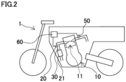
- a vehicle 1 of Second Embodiment of the present teaching will be described with reference to FIG. 2 .
- the vehicle 1 of Second Embodiment includes the following arrangements, in addition to those of the First Embodiment.
- the vehicle 1 of the Second Embodiment includes a catalyst 21 provided in an exhaust passage member 30.
- An oxygen sensor 20 is an upstream oxygen sensor 20 provided upstream of a catalyst 21 in a flow direction of exhaust gas of the exhaust passage member 30.
- the upstream oxygen sensor 20 is used for fuel control.
- the controller 60 performs the fuel control based on a signal of the upstream oxygen sensor 20.
- the controller 60 diagnoses the deterioration of the upstream oxygen sensor 20 in an oxygen sensor diagnosis process.
- a vehicle 1 of the Third Embodiment of the present teaching will be described with reference to FIG. 3 .
- the vehicle 1 of the Third Embodiment includes the following arrangements, in addition to those of the Second Embodiment.
- An engine 10 of the vehicle 1 of the Third Embodiment is a four-stroke engine. As shown in FIG. 3 , the engine 10 includes a cylinder body 12 and a cylinder head 14. At least one cylinder hole 13 is formed in the cylinder body 12. A piston 15 is slidably accommodated in the cylinder hole 13. The piston 15 is connected to a crankshaft (not illustrated) through a connecting rod.
- the engine 10 includes at least one combustion chamber 11. The combustion chamber 11 is formed of the cylinder hole 13 of the cylinder body 12, the piston 15, and the cylinder head 14. A leading end portion of an ignition plug (not illustrated) is provided in the combustion chamber 11. By spark discharge generated by the ignition plug, the air-fuel mixture in the combustion chamber 11 is ignited. The ignition plug is connected to an ignition coil (not illustrated).
- the at least one combustion chamber 11 is connected to an intake passage member 40 and the exhaust passage member 30.
- the intake passage member 40 includes a cylinder head intake passage member 41 formed in the cylinder head 14 and an intake pipe member 42. In the cylinder head intake passage member 41, an intake valve (not illustrated) is provided.
- the intake pipe member 42 includes an air cleaner (not illustrated).
- the exhaust passage member 30 includes a cylinder head exhaust passage member 31 formed in the cylinder head 14 and an exhaust pipe member 32. In the cylinder head exhaust passage member 31, an exhaust valve (not illustrated) is provided.
- the exhaust pipe member 32 includes a muffler (not illustrated). The intake pipe member 42 and the exhaust pipe member 32 are connected to the engine 10.
- the fuel supplier 50 includes at least one injector 51 and a fuel pump 52.
- the injector 51 is provided in the intake passage member 40.
- the injector 51 is configured to inject fuel.
- Fuel pressurized by the fuel pump 52 is supplied to the injector 51.
- the fuel pump 52 is disposed in a fuel tank 53.
- At least one throttle valve 70 is provided in the intake passage member 40.
- the throttle valve 70 is provided upstream of the injector 51 in a flow direction of air.
- the throttle valve 70 is an electronic-controlled throttle valve.
- the throttle valve 70 may be a mechanical throttle valve.
- the controller 60 is connected to members such as the injector 51, the fuel pump 52, and the ignition coil (not illustrated) and controls these members.
- the controller 60 is configured to control a fuel amount supplied to the at least one combustion chamber 11 by controlling the injector 51 and the fuel pump 52.
- the controller 60 is configured to perform fuel control by controlling the injector 51 and the fuel pump 52.
- the controller 60 controls an ignition timing by controlling the ignition coil.
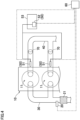
- a vehicle 1 of the Fourth Embodiment of the present teaching will be described with reference to FIG. 4 .
- the vehicle 1 of the Fourth Embodiment includes the following arrangements, in addition to those of the Third Embodiment.
- an engine 10 of the vehicle 1 of the Fourth Embodiment includes plural combustion chambers 11. While in FIG. 4 the engine 10 has two combustion chambers 11, the engine 10 may have three or more combustion chambers 11.
- the vehicle 1 includes one throttle valve 70 for each of the combustion chambers 11.
- the vehicle 1 includes one injector 51 for each of the combustion chambers 11.
- the vehicle 1 includes one oxygen sensor 20 for the combustion chambers 11.
- the vehicle 1 includes one catalyst 21 for the combustion chambers 11.
- the vehicle 1 may include one oxygen sensor 20 for each of the combustion chambers 11.
- the vehicle 1 may include one catalyst 21 for each of the combustion chambers 11.
- FIG. 5(a) shows the vehicle 1 of the Fifth Embodiment
- FIG. 5(b) shows the vehicle 1 of the Sixth Embodiment
- the vehicle 1 of each of the Fifth Embodiment and Sixth Embodiment may have the features of the Third Embodiment.
- the vehicle 1 of each of the Fifth Embodiment and Sixth Embodiment may or may not have the features of the Fourth Embodiment.
- the vehicle 1 of each of the Fifth Embodiment and Sixth Embodiment have the following features, in addition to the features of the Second Embodiment.
- the vehicle 1 of each of the Fifth Embodiment and Sixth Embodiment is a straddled vehicle.
- the vehicle 1 has a seat 80.
- a vehicle front-rear direction is the front-rear direction for a rider seated on the seat 80.
- a vehicle left-right direction is the left-right direction for the rider seated on the seat 80.
- a vehicle left-right direction coincides with a vehicle width direction.
- a vehicle up-down direction is a direction orthogonal to both the vehicle front-rear direction and the vehicle left-right direction.
- An arrow F and an arrow Re in the figures indicate a vehicle forward direction and a vehicle rearward direction, respectively.
- An arrow U and an arrow D indicate a vehicle upward direction and a vehicle downward direction, respectively.
- the engine 10 of the vehicle 1 of each of the Fifth Embodiment and Sixth Embodiment includes at least one combustion chamber 11.
- the engine 10 has at least one cylinder hole 13.
- the cylinder hole 13 constitutes part of the combustion chamber 11.
- the central axis of the cylinder hole 13 is referred to as a cylinder axis Cy.
- a piston (not illustrated) is slidably accommodated in the cylinder hole 13.
- the piston is connected to a crankshaft (not illustrated).
- the central axial line of the crankshaft is referred to as a crankshaft Cl.
- the crankshaft Cl is in parallel to the vehicle left-right direction.
- the cylinder axis Cy of the vehicle 1 of the Fifth Embodiment is in parallel to the vehicle up-down direction or is tilted by 45 degrees or less from the vehicle up-down direction.
- the cylinder axis Cy of the vehicle 1 of the Sixth Embodiment is in parallel to the vehicle front-rear direction or is tilted by 45 degrees or less from the vehicle front-rear direction.
- an oxygen sensor (upstream oxygen sensor) 20 of each of the Fifth Embodiment and Sixth Embodiment may be provided above a straight line SL1 that is orthogonal to the cylinder axis Cy and passes through the crankshaft Cl.
- the oxygen sensor 20 When the oxygen sensor 20 is provided above the straight line SL1 when viewed in the vehicle left-right direction, the oxygen sensor 20 is close to the combustion chamber 11 and hence the temperature of the oxygen sensor 20 is high, as compared to a case where the oxygen sensor 20 is at least partially below the straight line SL1 when viewed in the vehicle left-right direction.
- the catalyst 21 When viewed in the vehicle left-right direction, the catalyst 21 may be at least partially above the straight line SL1 that is orthogonal to the cylinder axis Cy and passes through the crankshaft Cl. When viewed in the vehicle left-right direction, the catalyst 21 may be entirely above the straight line SL1 that is orthogonal to the cylinder axis Cy and passes through the crankshaft Cl.
- the responsiveness of the oxygen sensor 20 varies in accordance with the engine rotation speed and/or the engine load.
- the controller 60 performs diagnoses by a diagnosis method changed at least in accordance with the engine rotation speed, while the normal fuel control is performed and the fuel cut control is not performed.
- the controller 60 performs the oxygen sensor diagnosis process to satisfy the relationship 3 or 4 of the First Embodiment, the controller 60 performs a diagnosis by a diagnosis method changed at least in accordance with the engine load, while the normal fuel control is performed and the fuel cut control is not performed.
- the vehicle 1 of each of the Fifth Embodiment and Sixth Embodiment has the features of the Fourth Embodiment or when the engine 10 of the vehicle 1 of each of the Fifth Embodiment and Sixth Embodiment is a single-cylinder engine having one combustion chamber 11, the vehicle 1 of each of the Fifth Embodiment and Sixth Embodiment has an independent-throttle engine unit.
- Straddled vehicles have been required to be downsized.
- a straddled vehicle is smaller in size than an automobile. It is therefore difficult to downsize the straddled vehicle.
- the accuracy of fuel control based on a signal of the upstream oxygen sensor decreases.
- the purification performance of purifying exhaust gas by the catalyst may decrease.
- the size of the catalyst of a known straddled vehicle is arranged to be sufficiently large to secure a margin.
- the driving range (the rotation range and the load range) of the engine 10 of each of the Fifth Embodiment and Sixth Embodiment is wider than the driving range of an engine of an automobile having a collective-throttle engine unit.
- the responsiveness of the oxygen sensor 20 varies in accordance with the engine rotation speed
- the wider the rotation range is, the wider the range of variation of the responsiveness of the oxygen sensor 20 in accordance with the engine rotation speed is.
- the responsiveness of the oxygen sensor 20 varies in accordance with the engine load
- the wider the load range is, the wider the range of variation of the responsiveness of the oxygen sensor 20 in accordance with the engine load is.
- the range of variation of the responsiveness of the oxygen sensor 20 in accordance with the engine rotation speed and/or the engine load is wide, as compared to an automobile having a narrow driving range.
- the range of variation of the responsiveness of the oxygen sensor in accordance with the engine rotation speed and/or the engine load is narrow.
- the frequency of diagnosis remains more or less the same as compared to a case where the method is not changed.
- the method of diagnosing the deterioration of the oxygen sensor of the straddled vehicle remains the same irrespective of the engine rotation speed and the engine load, the accuracy of the diagnosis is secured only in a part of the driving range of the engine of the straddled vehicle.
- the frequency of diagnosis is significantly increased as compared to cases where the method is not changed.
- the ratio of the diagnosable range in the driving range is lower in the straddled vehicle than in the automobile.
- the frequency of the diagnosis of deterioration of the oxygen sensor 20 can be further effectively improved as compared to the case of the automobile.
- the frequency of diagnosis is improved while the accuracy of diagnosis is maintained or improved, it is possible to suppress the decrease of accuracy of fuel control due to decrease of responsiveness of the oxygen sensor 20.
- the vehicle 1 of the Seventh Embodiment may have the features of the Fourth Embodiment.
- the vehicle 1 of the Seventh Embodiment may or may not have the features of the Fifth or Sixth Embodiment.
- the vehicle 1 of the Seventh Embodiment includes the following arrangements, in addition to those of the Third Embodiment.
- the vehicle 1 of the Seventh Embodiment includes members such as an engine rotation speed sensor 61 and a throttle position sensor 62, in addition to the oxygen sensor (upstream oxygen sensor) 20.
- the engine rotation speed sensor 61 is configured to detect the rotation speed of the crankshaft, i.e., the engine rotation speed.
- the throttle position sensor 62 is configured to detect the opening degree of the throttle valve 70.
- the controller 60 performs normal fuel control based on, for example, signals of the oxygen sensor (upstream oxygen sensor) 20, the engine rotation speed sensor 61, and the throttle position sensor 62.
- the normal fuel control encompasses fuel amount variation control of increasing and decreasing a fuel supply amount and fuel cut control of temporarily stopping supply of fuel to at least one combustion chamber 11.
- the fuel supply amount is a fuel amount supplied to the at least one combustion chamber 11.
- the controller 60 determines the fuel supply amount by adding or subtracting a correction amount to or from a basic fuel amount.
- the controller 60 calculates an intake air amount based on, for example, signals of the engine rotation speed sensor 61 and the throttle position sensor 62.
- the intake air amount is an amount of air supplied to the at least one combustion chamber 11.
- the controller 60 determines a basic fuel amount based on the calculated intake air amount.
- the controller 60 determines the correction amount based on a signal of the oxygen sensor (upstream oxygen sensor) 20.
- the controller 60 performs the fuel amount variation control of the normal fuel control in order to maintain the air-fuel ratio of air-fuel mixture at a target air-fuel ratio.
- the controller 60 starts the fuel cut control when, for example, the normal fuel control is being performed, the opening degree of the throttle valve 70 is at the minimum, and the engine rotation speed is higher than a predetermined value. While the fuel cut control is performed, the injection of the fuel from the injector 51 is stopped and the fuel pump 52 is stopped.
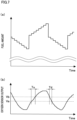
- the fuel amount supplied to one combustion chamber 11 increases and decreases as shown in FIG. 7(a) , for example.
- an output (signal) of the oxygen sensor (upstream oxygen sensor) 20 varies as shown in FIG. 7(b) , for example. Even though the oxygen sensor 20 is normal, a change of the signal output from the oxygen sensor 20 delays from a change in the oxygen concentration.
- the waveform of the signal of the oxygen sensor (upstream oxygen sensor) 20 is not square. It is noted that the waveform is different between the case where the oxygen sensor (upstream oxygen sensor) 20 is an O2 sensor and the case where the oxygen sensor (upstream oxygen sensor) 20 is a linear A/F sensor.
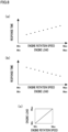
- the responsiveness of the oxygen sensor 20 varies in accordance with the engine rotation speed and/or the engine load. Depending on the type of the vehicle 1, the tendency of changes in the responsiveness of the oxygen sensor 20 in accordance with the engine rotation speed and/or the engine load is different. There are a case where the responsiveness of the oxygen sensor 20 decreases as the engine rotation speed and/or the engine load increases, and a case where the responsiveness of the oxygen sensor 20 decreases as the engine rotation speed and/or the engine load decreases.
- a graph shown in FIG. 8(a) shows the former case, whereas a graph shown in FIG. 8(b) shows the latter case.
- each of the graphs of FIG. 8(a) and FIG. 8(b) indicates a combination of an engine rotation speed and an engine load.
- the transverse axis of each of the graphs of FIG. 8(a) and FIG. 8(b) is equivalent to a diagonal line of a graph of FIG. 8(c) in which the transverse axis indicates an engine rotation speed whereas the vertical axis indicates an engine load.
- the vertical axis of each of the graphs of FIG. 8(a) and FIG. 8(b) indicates a response time of a signal of the oxygen sensor 20.
- the response time is, for example, a rise response time Tu or a fall response time Td shown in FIG. 7(b) .
- the rise response time Tu is a time required for changing the signal of the oxygen sensor 20 by a unit amount when the signal of the oxygen sensor 20 is on the rise.
- the fall response time Td is a time required for changing the signal of the oxygen sensor 20 by a unit amount when the signal of the oxygen sensor 20 is on the decline.
- the unit amount of the rise response time Tu shown in FIG. 7(b) is an amount from an output Va to an output Vb.
- the unit amount of the rise response time Tu is not limited to this.
- the unit amount of the fall response time Td shown in FIG. 7(b) is an amount from an output Vb to an output Va.
- the unit amount of the fall response time Td is not limited to this.
- the longer the response time is, the lower the responsiveness of the oxygen sensor 20 is. Dots in the graph of FIG. 8(a) indicate response times of the oxygen sensor 20, with which the degree of deterioration is the same. The same applies to dots in the graph of FIG. 8(b) .
- the reasons why the responsiveness of the signal of the oxygen sensor 20 decreases as the engine rotation speed and/or the engine load increases as shown in FIG. 8(a) are, for example, two reasons described below.
- the response speed of the oxygen sensor 20 is low.
- the response speed of the oxygen sensor 20 decreases, the responsiveness of the oxygen sensor 20 decreases.
- the maximum value of the signal (output) of the oxygen sensor 20 decreases as the temperature of the oxygen sensor 20 increases.
- the maximum value of the signal of the oxygen sensor 20 decreases, the responsiveness of the oxygen sensor 20 decreases.
- the engine rotation speed and the engine load are high, the temperature of the oxygen sensor 20 is high.
- the temperature of the oxygen sensor 20 reaches a temperature with which the response speed of the oxygen sensor 20 is maximized.
- the responsiveness of the oxygen sensor 20 decreases as the engine rotation speed and the engine load increase. This is the first reason.
- the second reason is that the speed of a change in the oxygen concentration of exhaust gas hitting the oxygen sensor 20 increases as the engine rotation speed increases, and the oxygen sensor 20 is no longer able to respond.
- the reason why the responsiveness of the signal of the oxygen sensor 20 decreases as the engine rotation speed and/or the engine load decreases as shown in FIG. 8(b) is, for example, a reason described below.
- the temperature of the oxygen sensor 20 does not reach a temperature with which the response speed of the oxygen sensor 20 is maximized, and in a high-rotation high-load range, the temperature of the oxygen sensor 20 reaches the temperature with which the response speed of the oxygen sensor 20 is maximized. In this case, the response speed of the oxygen sensor 20 decreases as the engine rotation speed and the engine load decrease.
- the temperature of the oxygen sensor 20 is low in the case where the responsiveness of the signal of the oxygen sensor 20 decreases as the engine rotation speed and/or the engine load decreases as shown in FIG. 8(b) .
- the characteristic shown in FIG. 8(b) may be changed to the characteristic shown in FIG. 8(a) .
- the controller 60 performs the oxygen sensor diagnosis process to satisfy at least one of the following relationships 1 to 4 while the normal fuel control is performed and the fuel cut control is not performed. Due to this, the controller 60 performs a diagnosis by a diagnosis method changed in accordance with the engine rotation speed and/or the engine load, while the normal fuel control is performed and the fuel cut control is not performed.
- a time required for performing the oxygen sensor diagnosis process once is, for example, 300 to 600 seconds.
- the controller 60 performs Specific Example 1 or Specific Example 2 of the oxygen sensor diagnosis process, which are described below.
- the controller 60 diagnoses the deterioration of the oxygen sensor 20 by comparing a calculated value obtained from a signal of the oxygen sensor 20, etc., and related to the responsiveness of the oxygen sensor 20 with a threshold changed in accordance with the engine rotation speed and/or the engine load.
- the controller 60 corrects a calculated value obtained from a signal of the oxygen sensor 20, etc., and related to the responsiveness of the oxygen sensor 20, in accordance with the engine rotation speed and/or the engine load. Then the controller 60 diagnoses the deterioration of the oxygen sensor 20 by comparing the calculated value having been corrected with a threshold.
- the calculated value to be compared with the threshold may be, for example, a rise response time Tu of a signal of the oxygen sensor 20, a fall response time Td of a signal of the oxygen sensor 20, a rise amount of a signal of the oxygen sensor 20, or a fall amount of a signal of the oxygen sensor 20.
- the rise amount is an amount of change of a signal of the oxygen sensor 20 per unit time when the signal of the oxygen sensor 20 is on the rise.
- the fall amount is an amount of change of a signal of the oxygen sensor 20 per unit time when the signal of the oxygen sensor 20 is on the decline.
- the smaller the rise amount is, the lower the responsiveness of the oxygen sensor 20 is.
- the controller 60 determines that the oxygen sensor 20 has been deteriorated.
- the controller 60 determines that the oxygen sensor 20 has been deteriorated.
- the calculated value to be compared with the threshold may be an average, a deviation value, a median, the minimum, or the maximum of the rise response time Tu, the fall response time Td, the rise amount, or the fall amount.
- the calculated value to be compared with the threshold may be a combination of the rise response time Tu and the fall response time Td.
- the calculated value to be compared with the threshold may be a combination of the rise amount and the fall amount.
- the threshold is changed in accordance with the engine rotation speed and/or the engine load.
- the controller 60 may determine the threshold based on an intake air amount or the opening degree of the throttle valve 70.
- the threshold may be changed in accordance with the engine rotation speed and the engine load.
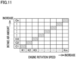
- the controller 60 may determine the threshold by using a lookup table (see, e.g., FIG. 11 ) in which the engine rotation speed, the intake air amount, and the threshold are associated.
- the threshold may be changed in accordance with the engine rotation speed, irrespective of the engine load.
- the oxygen sensor diagnosis process is simplified.
- the threshold may be changed in accordance with the engine load, irrespective of the engine rotation speed.
- the responsiveness of the oxygen sensor 20 greatly depends not on the engine rotation speed but on the engine load, the use of this threshold improves the frequency of diagnosis without compromising on the accuracy of diagnosis.
- the oxygen sensor diagnosis process is simplified.
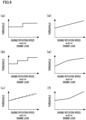
- FIG. 9(a) to FIG. 9(f) and FIG. 10(a) to FIG. 10(f) show examples of the threshold that is changed in accordance with the engine rotation speed and/or the engine load.
- the transverse axis of the graph in each of FIG. 9(a) to FIG. 9(f) and FIG. 10(a) to FIG. 10(f) indicates the engine rotation speed, the engine load, or a combination of the engine rotation speed and the engine load.
- the graph in each of FIG. 9(a) to FIG. 9(f) and FIG. 10(a) to FIG. 10(f) shows only a threshold in a small part of the driving range of the engine 10.
- the graphs show thresholds in a range hutched in the lookup table shown in FIG. 11 .
- the threshold increases as the engine rotation speed and/or the engine load increases.
- the threshold increases as the engine rotation speed and/or the engine load decreases.
- the threshold in each of FIG. 9(a) to FIG. 9(f) is, for example, a threshold to be compared with the rise response time Tu or the fall response time Td.
- the threshold in each of FIG. 9(a) to FIG. 9(f) is, for example, a threshold to be compared with the rise amount or the fall amount.
- the threshold may be changed stepwise in accordance with the engine rotation speed and/or the engine load.
- the threshold may be changed in two steps (as shown in, e.g., FIG. 9(a) and FIG. 10(a) ) or may be changed in three or more steps (as shown in, e.g., FIG. 9(b), FIG. 9(c) , FIG. 10(b), and FIG. 10(c) ).
- the threshold may be changed continuously in accordance with the engine rotation speed and/or the engine load.
- the rate of change of the threshold relative to a change of the engine rotation speed and/or the engine load may be constant (as shown in, e.g., FIG. 9(d) and FIG. 10(d) ) or may be changed in accordance with the engine rotation speed and/or the engine load (as shown in, e.g., FIG. 9(e), FIG. 9(f) , FIG. 10(e), and FIG. 10(f) ).
- the threshold in Specific Example 2 is constant irrespective of the engine rotation speed and the engine load.
- Examples of the calculated value before correction are identical with the examples of the calculated value which is to be compared with the threshold in Specific Example 1.
- the correction may be addition, subtraction, multiplication, or division.
- the calculation may be a number sampling through mapping by using a lookup table.
- the value added to the calculated value, subtracted from the calculated value, by which the calculated value is multiplied, or by which the calculated value is divided is referred to as a correction value.
- the correction value is a coefficient of the multiplication or division.
- the correction value is changed in accordance with the engine rotation speed and/or the engine load.
- the controller 60 may determine the correction value based on an intake air amount or the opening degree of the throttle valve 70.
- the correction value may be changed in accordance with the engine rotation speed and the engine load.
- the controller 60 may determine the correction value by using a lookup table (see, e.g., FIG. 11 ) in which the engine rotation speed, the intake air amount, and the correction value are associated.
- the correction value may be changed in accordance with the engine rotation speed, irrespective of the engine load.
- the oxygen sensor diagnosis process is simplified.
- the correction value may be changed in accordance with the engine load, irrespective of the engine rotation speed.
- the use of this correction value improves the frequency of diagnosis without compromising on the accuracy of diagnosis.
- the engine rotation speed is not referred to, the oxygen sensor diagnosis process is simplified.
- FIG. 13(a) to FIG. 13(f) show examples of the correction value that is changed in accordance with the engine rotation speed and/or the engine load.
- the transverse axis of the graph in each of FIG. 13(a) to FIG. 13(f) indicates the engine rotation speed, the engine load, or a combination of the engine rotation speed and the engine load.
- the correction value decreases as the engine rotation speed and/or the engine load increases.
- the correction value may decrease as the engine rotation speed and/or the engine load decreases.
- the correction value in each of FIG. 13(a) to FIG. 13(f) is, for example, a value by which the rise response time Tu or the fall response time Td is corrected.
- the correction value in each of FIG. 13(a) to FIG. 13(f) is, for example, a value by which the rise amount or the fall amount is corrected.
- the correction value may be changed stepwise in accordance with the engine rotation speed and/or the engine load.
- the correction value may be changed in two steps or may be changed in three or more steps.
- the correction value may be changed continuously in accordance with the engine rotation speed and/or the engine load.
- the rate of change of the correction value relative to a change of the engine rotation speed and/or the engine load may be constant or may be changed in accordance with the engine rotation speed and/or the engine load.
- the controller 60 performs the oxygen sensor diagnosis process so as to satisfy the relationship 1 described in the First Embodiment and relationships 5 and 6 described below.
- this case is a case where the transverse axis of each of the graphs of FIG. 9(d) to FIG. 9(f) indicates either the engine rotation speed or a combination of the engine rotation speed and the engine load and the calculated value to be compared with the threshold is either the rise response time Tu or the fall response time.
- the case above is a case where the transverse axis of each of the graphs of FIG. 10(d) to FIG. 10(f) indicates either the engine rotation speed or a combination of the engine rotation speed and the engine load and the calculated value to be compared with the threshold is either the rise amount or the fall amount.
- the case above is a case where the transverse axis of each of the graphs of FIG. 13(d) to FIG. 13(f) indicates either the engine rotation speed or a combination of the engine rotation speed and the engine load and the correction value is a value by which the rise response time Tu or the fall response time Td is corrected.
- FIG. 14 shows an example of each of the relationships 5 and 6.
- Relationship 5 In at least part of the low-rotation range, the controller 60 diagnoses that the oxygen sensor 20 is normal when the first response time is equal to the first low-rotation response time TLoS1, and the controller 60 diagnoses that the oxygen sensor 20 is deteriorated when the first response time is equal to the second low-rotation response time TLoS2 that is longer than the first low-rotation response time TLoS1.
- the controller 60 diagnoses that the oxygen sensor 20 is normal when the first response time is equal to a first high-rotation response time THiS1 that is longer than the second low-rotation response time TLoS2, and the controller 60 diagnoses that the oxygen sensor 20 is deteriorated when the first response time is equal to a second high-rotation response time THiS2 that is longer than the first high-rotation response time THiS1.
- the controller 60 diagnoses that the oxygen sensor 20 is normal when the first response time is equal to a fifth high-rotation response time THiS5 that is longer than the second low-rotation response time TLoS2, and the controller 60 diagnoses that the oxygen sensor 20 is deteriorated when the first response time is equal to a sixth high-rotation response time THiS6 that is longer than the fifth high-rotation response time THiS5.
- Relationship 6 In at least part of a first low-rotation range RLoS1 included in the low-rotation range, the controller 60 diagnoses that the oxygen sensor 20 is normal when the first response time is equal to the first low-rotation response time TLoS1, and the controller 60 diagnoses that the oxygen sensor 20 is deteriorated when the first response time is equal to the second low-rotation response time TLoS2 that is longer than the first low-rotation response time TLoS1.
- the controller 60 diagnoses that the oxygen sensor 20 is normal when the first response time is equal to a fifth low-rotation response time TLoS5 that is longer than the second low-rotation response time TLoS2, and the controller 60 diagnoses that the oxygen sensor 20 is deteriorated when the first response time is equal to a sixth low-rotation response time TLoS6 that is longer than the fifth low-rotation response time TLoS5.
- the controller 60 diagnoses that the oxygen sensor 20 is normal when the first response time is equal to the first high-rotation response time THiS1 that is longer than the sixth low-rotation response time TLoS6, and the controller 60 diagnoses that the oxygen sensor 20 is deteriorated when the first response time is equal to a second high-rotation response time THiS2 that is longer than the first high-rotation response time THiS1.
- the controller 60 performs the oxygen sensor diagnosis process so as to satisfy the relationship 2 described in the First Embodiment and relationships 7 and 8 described below.
- FIG. 14 shows an example of each of the relationships 7 and 8.
- Relationship 7 In at least part of the high-rotation range, the controller 60 diagnoses that the oxygen sensor 20 is normal when the second response time is equal to the third high-rotation response time THiS3, and the controller 60 diagnoses that the oxygen sensor 20 is deteriorated when the second response time is equal to the fourth high-rotation response time THiS4 that is longer than the third high-rotation response time THiS3.
- the controller 60 diagnoses that the oxygen sensor 20 is normal when the second response time is equal to a third low-rotation response time TLoS3 that is longer than the fourth high-rotation response time THiS4, and the controller 60 diagnoses that the oxygen sensor 20 is deteriorated when the second response time is equal to a fourth low-rotation response time TLoS4 that is longer than the third low-rotation response time TLoS3.
- the controller 60 diagnoses that the oxygen sensor 20 is normal when the second response time is equal to a seventh low-rotation response time TLoS7 that is longer than the fourth low-rotation response time TLoS4, and the controller 60 diagnoses that the oxygen sensor 20 is deteriorated when the second response time is equal to an eighth low-rotation response time TLoS8 that is longer than the seventh low-rotation response time TLoS7.
- Relationship 8 In at least part of a third high-rotation range RHiS3 included in the high-rotation range, the controller 60 diagnoses that the oxygen sensor 20 is normal when the second response time is equal to the third high-rotation response time THiS3, and the controller 60 diagnoses that the oxygen sensor 20 is deteriorated when the second response time is equal to the fourth high-rotation response time THiS4 that is longer than the third high-rotation response time THiS3.
- the controller 60 diagnoses that the oxygen sensor 20 is normal when the second response time is equal to a seventh high-rotation response time THiS7 that is longer than the fourth high-rotation response time THiS4, and the controller 60 diagnoses that the oxygen sensor 20 is deteriorated when the second response time is equal to an eighth high-rotation response time THiS8 that is longer than the seventh high-rotation response time THiS7.
- the controller 60 diagnoses that the oxygen sensor 20 is normal when the second response time is equal to the third low-rotation response time TLoS3 that is longer than the eighth high-rotation response time THiS8, and the controller 60 diagnoses that the oxygen sensor 20 is deteriorated when the second response time is equal to a fourth low-rotation response time TLoS4 that is longer than the third low-rotation response time TLoS3.
- the controller 60 performs the oxygen sensor diagnosis process so as to satisfy the relationships 1 and 5.
- the controller 60 performs the oxygen sensor diagnosis process so as to satisfy the relationships 1 and 6.
- the controller 60 performs the oxygen sensor diagnosis process so as to satisfy the relationships 2 and 7.
- the controller 60 performs the oxygen sensor diagnosis process so as to satisfy the relationships 2 and 8.
- the controller 60 performs the oxygen sensor diagnosis process so as to satisfy the relationship 3 described in the First Embodiment and relationships 9 and 10 described below.
- FIG. 14 shows an example of each of the relationships 9 and 10.
- Relationship 9 In at least part of the low-load range, the controller 60 diagnoses that the oxygen sensor 20 is normal when the third response time is equal to the first low-load response time TLoL1, and the controller 60 diagnoses that the oxygen sensor 20 is deteriorated when the third response time is equal to a second low-load response time TLoL2 that is longer than the first low-load response time TLoL1.
- the controller 60 diagnoses that the oxygen sensor 20 is normal when the third response time is equal to a first high-load response time THiL1 that is longer than the second low-load response time TLoL2, and the controller 60 diagnoses that the oxygen sensor 20 is deteriorated when the third response time is equal to a second high-load response time THiL2 that is longer than the first high-load response time THiL1.
- the controller 60 diagnoses that the oxygen sensor 20 is normal when the third response time is equal to a fifth high-load response time THiL5 that is longer than the second low-load response time TLoL2, and the controller 60 diagnoses that the oxygen sensor 20 is deteriorated when the third response time is equal to a sixth high-load response time THiL6 that is longer than the fifth high-load response time THiL5.
- Relationship 10 In at least part of a first low-load range RLoL1 included in the low-load range, the controller 60 diagnoses that the oxygen sensor 20 is normal when the third response time is equal to the first low-load response time TLoL1, and the controller 60 diagnoses that the oxygen sensor 20 is deteriorated when the third response time is equal to a second low-load response time TLoL2 that is longer than the first low-load response time TLoL1.
- the controller 60 diagnoses that the oxygen sensor 20 is normal when the third response time is equal to a fifth low-load response time TLoL5 that is longer than the second low-load response time TLoL2, and the controller 60 diagnoses that the oxygen sensor 20 is deteriorated when the third response time is equal to a sixth low-load response time TLoL6 that is longer than the fifth low-load response time TLoL5.
- the controller 60 diagnoses that the oxygen sensor 20 is normal when the third response time is equal to the first high-load response time THiL1 that is longer than the sixth low-load response time TLoL6, and the controller 60 diagnoses that the oxygen sensor 20 is deteriorated when the third response time is equal to a second high-load response time THiL2 that is longer than the first high-load response time THiL1.
- the controller 60 performs the oxygen sensor diagnosis process so as to satisfy the relationship 4 described in the First Embodiment and relationships 11 and 12 described below.
- FIG. 14 shows an example of each of the relationships 11 and 12.
- Relationship 11 In at least part of the high-load range, the controller 60 diagnoses that the oxygen sensor 20 is normal when the fourth response time is equal to the third high-load response time THiL3, and the controller 60 diagnoses that the oxygen sensor 20 is deteriorated when the fourth response time is equal to the fourth high-load response time THiL4 that is longer than the third high-load response time THiL3.
- the controller 60 diagnoses that the oxygen sensor 20 is normal when the fourth response time is equal to a third low-load response time TLoL3 that is longer than the fourth high-load response time THiL4 and the controller 60 diagnoses that the oxygen sensor 20 is deteriorated when the fourth response time is equal to a fourth low-load response time TLoL4 that is longer than the third low-load response time TLoL3.
- the controller 60 diagnoses that the oxygen sensor 20 is normal when the fourth response time is equal to a seventh low-load response time TLoL7 that is longer than the fourth low-load response time TLoL4 and the controller 60 diagnoses that the oxygen sensor 20 is deteriorated when the fourth response time is equal to an eighth low-load response time TLoL8 that is longer than the seventh low-load response time TLoL7.
- Relationship 12 In at least part of a third high-load range RHiL3 included in the high-load range, the controller 60 diagnoses that the oxygen sensor 20 is normal when the fourth response time is equal to the third high-load response time THiL3, and the controller 60 diagnoses that the oxygen sensor 20 is deteriorated when the fourth response time is equal to the fourth high-load response time THiL4 that is longer than the third high-load response time THiL3.
- the controller 60 diagnoses that the oxygen sensor 20 is normal when the fourth response time is equal to a seventh high-load response time THiL7 that is longer than the fourth high-load response time THiL4 and the controller 60 diagnoses that the oxygen sensor 20 is deteriorated when the fourth response time is equal to an eighth high-load response time THiL8 that is longer than the seventh high-load response time THiL7.
- the controller 60 diagnoses that the oxygen sensor 20 is normal when the fourth response time is equal to the third low-load response time TLoL3 that is longer than the eighth high-load response time THiL8 and the controller 60 diagnoses that the oxygen sensor 20 is deteriorated when the fourth response time is equal to a fourth low-load response time TLoL4 that is longer than the third low-load response time TLoL3.
- the controller 60 performs the oxygen sensor diagnosis process so as to satisfy the relationships 3 and 9.
- the controller 60 performs the oxygen sensor diagnosis process so as to satisfy the relationships 3 and 10.
- the controller 60 performs the oxygen sensor diagnosis process so as to satisfy the relationships 4 and 11.
- the controller 60 performs the oxygen sensor diagnosis process so as to satisfy the relationships 4 and 12.
- the controller 60 When the controller 60 performs the oxygen sensor diagnosis process to satisfy at least one of the relationships 5 to 12, the frequency of diagnosis of deterioration of the oxygen sensor 20 is further increased.
- the controller 60 performs the oxygen sensor diagnosis process to satisfy the relationship 1 and a relationship 13 described below.
- FIG. 15 shows two examples of the relationship 13.
- Relationship 13 In a first load range RL1 which is either at least part of the low-load range or at least part of the high-load range and in at least part of the low-rotation range, the controller 60 diagnoses that the oxygen sensor 20 is normal when the first response time is equal to the first low-rotation response time TLoS1, and the controller 60 diagnoses that the oxygen sensor 20 is deteriorated when the first response time is equal to the second low-rotation response time TLoS2 that is longer than the first low-rotation response time TLoS1.
- the controller 60 diagnoses that the oxygen sensor 20 is normal when the first response time is equal to the first high-rotation response time THiS1 that is longer than the second low-rotation response time TLoS2, and the controller 60 diagnoses that the oxygen sensor 20 is deteriorated when the first response time is equal to a second high-rotation response time THiS2 that is longer than the first high-rotation response time THiS1.
- the controller 60 performs the oxygen sensor diagnosis process to satisfy the relationship 2 and a relationship 14 described below.
- FIG. 15 shows two examples of the relationship 14.
- Relationship 14 In a second load range RL2 which is either at least part of the low-load range or at least part of the high-load range and in at least part of the high-rotation range, the controller 60 diagnoses that the oxygen sensor 20 is normal when the second response time is equal to the third high-rotation response time THiS3, and the controller 60 diagnoses that the oxygen sensor 20 is deteriorated when the second response time is equal to the fourth high-rotation response time THiS4 that is longer than the third high-rotation response time THiS3.
- the controller 60 diagnoses that the oxygen sensor 20 is normal when the second response time is equal to the third low-rotation response time TLoS3 that is longer than the fourth high-rotation response time THiS4, and the controller 60 diagnoses that the oxygen sensor 20 is deteriorated when the second response time is equal to a fourth low-rotation response time TLoS4 that is longer than the third low-rotation response time TLoS3.
- the controller 60 performs the oxygen sensor diagnosis process to satisfy the relationship 3 and a relationship 15 described below.
- FIG. 16 shows two examples of the relationship 15.
- Relationship 15 In a first rotation range RS1 which is either at least part of the low-rotation range or at least part of the high-rotation range and in at least part of the low-load range, the controller 60 diagnoses that the oxygen sensor 20 is normal when the third response time is equal to the first low-load response time TLoL1, and the controller 60 diagnoses that the oxygen sensor 20 is deteriorated when the third response time is equal to the second low-load response time TLoL2 that is longer than the first low-load response time TLoL1.
- the controller 60 diagnoses that the oxygen sensor 20 is normal when the third response time is equal to the first high-load response time THiL1 that is longer than the second low-load response time TLoL2 and the controller 60 diagnoses that the oxygen sensor 20 is deteriorated when the third response time is equal to a second high-load response time THiL2 that is longer than the first high-load response time THiL1.
- Relationship 16 In a second rotation range RS2 which is either at least part of the low-rotation range or at least part of the high-rotation range and in at least part of the high-load range, the controller 60 diagnoses that the oxygen sensor 20 is normal when the fourth response time is equal to the third high-load response time THiL3, and the controller 60 diagnoses that the oxygen sensor 20 is deteriorated when the fourth response time is equal to the fourth high-load response time THiL4 that is longer than the third high-load response time THiL3.
- the controller 60 diagnoses that the oxygen sensor 20 is normal when the fourth response time is equal to the third low-load response time TLoL3 that is longer than the fourth high-load response time THiL4 and the controller 60 diagnoses that the oxygen sensor 20 is deteriorated when the fourth response time is equal to a fourth low-load response time TLoL4 that is longer than the third low-load response time TLoL3.
- the controller 60 performs the oxygen sensor diagnosis process to satisfy the relationship 1 and a relationship 17 described below.
- FIG. 17 shows an example of the relationship 17.
- Relationship 17 In at least part of the low-load range and at least part of the low-rotation range, the controller 60 diagnoses that the oxygen sensor 20 is normal when the first response time is equal to the first low-rotation response time TLoS1, and the controller 60 diagnoses that the oxygen sensor 20 is deteriorated when the first response time is equal to the second low-rotation response time TLoS2 that is longer than the first low-rotation response time TLoS1.
- the controller 60 diagnoses that the oxygen sensor 20 is normal when the first response time is equal to a first high-rotation response time THiS1 that is longer than the second low-rotation response time TLoS2, and the controller 60 diagnoses that the oxygen sensor 20 is deteriorated when the first response time is equal to a second high-rotation response time THiS2 that is longer than the first high-rotation response time THiS1.
- the first response time is identical with the third response time of the relationship 3
- the first low-rotation response time TLoS1 is identical with the first low-load response time TLoL1 of the relationship 3
- the second low-rotation response time TLoS2 is identical with the second low-load response time TLoL2 of the relationship 3
- the first high-rotation response time THiS1 is identical with the first high-load response time THiL1 of the relationship 3
- the second high-rotation response time THiS2 is identical with the second high-load response time THiL2 of the relationship 3.
- the controller 60 performs the oxygen sensor diagnosis process to satisfy the relationship 2 and a relationship 18 described below.
- FIG. 17 shows an example of the relationship 18.
- Relationship 18 In at least part of the high-load range and at least part of the high-rotation range, the controller 60 diagnoses that the oxygen sensor 20 is normal when the second response time is equal to the third high-rotation response time THiS3, and the controller 60 diagnoses that the oxygen sensor 20 is deteriorated when the second response time is equal to the fourth high-rotation response time THiS4 that is longer than the third high-rotation response time THiS3.
- the controller 60 diagnoses that the oxygen sensor 20 is normal when the second response time is equal to the third low-rotation response time TLoS3 that is longer than the fourth high-rotation response time THiS4, and the controller 60 diagnoses that the oxygen sensor 20 is deteriorated when the second response time is equal to a fourth low-rotation response time TLoS4 that is longer than the third low-rotation response time TLoS3.
- the second response time is identical with the fourth response time of the relationship 4
- the third high-rotation response time THiS3 is identical with the third high-load response time THiL3 of the relationship 4
- the fourth high-rotation response time THiS4 is identical with the fourth high-load response time THiL4 of the relationship 4
- the third low-rotation response time TLoS3 is identical with the third low-load response time TLoL3 of the relationship 4
- the fourth low-rotation response time TLoS4 is identical with the fourth low-load response time TLoL4 of the relationship 4.
- the controller 60 performs the oxygen sensor diagnosis process to satisfy the relationship 17 or the relationship 18, the frequency of diagnosis of deterioration of the oxygen sensor 20 is further increased.
- the controller 60 may perform preliminary diagnosis and main diagnosis in the oxygen sensor diagnosis process.
- the main diagnosis may be performed only when the deterioration of the oxygen sensor 20 is found by the preliminary diagnosis.
- the diagnosis method may be identical or different between the preliminary diagnosis and the main diagnosis.
- the controller 60 may perform an oxygen sensor diagnosis process in which Specific Example 1 is combined with Specific Example 2.
- the controller 60 may perform below-described Specific Example 3 of the oxygen sensor diagnosis process, in place of Specific Example 1 or Specific Example 2 of the oxygen sensor diagnosis process.
- Specific Example 3 of the oxygen sensor diagnosis process the controller 60 changes the method of calculating a calculated value obtained from a signal of the oxygen sensor 20 and related to the responsiveness of the oxygen sensor 20, in accordance with the engine rotation speed and/or the engine load.
- the controller 60 diagnoses the deterioration of the oxygen sensor 20 by comparing the calculated value related to the responsiveness of the oxygen sensor 20 with a threshold. For example, a unit amount of a rise response time is changed in accordance with the engine rotation speed and/or the engine load.
- the controller 60 may perform an oxygen sensor diagnosis process in which at least two of Specific Example 1, Specific Example 2, or Specific Example 3 are combined.
Landscapes
- Engineering & Computer Science (AREA)
- Chemical & Material Sciences (AREA)
- Combustion & Propulsion (AREA)
- Mechanical Engineering (AREA)
- General Engineering & Computer Science (AREA)
- Electrical Control Of Air Or Fuel Supplied To Internal-Combustion Engine (AREA)
- Combined Controls Of Internal Combustion Engines (AREA)
- Exhaust Gas After Treatment (AREA)
Claims (7)
- Ein Fahrzeug (1), das folgende Merkmale aufweist:einen Motor (10), der zumindest eine Verbrennungskammer (11) umfasst;einen Sauerstoffsensor (20), der an einem Auslasskanalbauglied (30) vorgesehen ist, durch das Abgas, das aus der zumindest einen Verbrennungskammer (11) ausgelassen wird, verläuft, und der dazu konfiguriert ist, eine Sauerstoffkonzentration in dem Abgas zu erfassen;eine Kraftstoffzuführeinrichtung (50), die dazu konfiguriert ist, der zumindest einen Verbrennungskammer (11) Kraftstoff zuzuführen; undeine Steuereinrichtung (60), die dazu konfiguriert ist, einen Sauerstoffsensordiagnoseprozess zum Diagnostizieren einer Verschlechterung des Sauerstoffsensors (20) basierend auf einem Signal des Sauerstoffsensors (20) durchzuführen, und die dazu konfiguriert ist, eine Kraftstoffsteuerung zum Steuern einer Kraftstoffmenge, die der zumindest einen Verbrennungskammer (11) zugeführt wird, durch Steuern der Kraftstoffzuführeinrichtung (50) durchzuführen, undwenndie Kraftstoffsteuerung zum Steuern der Kraftstoffmenge, die der zumindest einen Verbrennungskammer (11) nicht zum Diagnostizieren der Verschlechterung des Sauerstoffsensors (20) zugeführt wird, als normale Kraftstoffsteuerung bezeichnet wird, unddie Kraftstoffsteuerung zum Steuern der Kraftstoffmenge, die der zumindest einen Verbrennungskammer zum Diagnostizieren der Verschlechterung des Sauerstoffsensors zugeführt wird, in der zumindest eines von einem Zyklus oder einer Amplitude einer Erhöhung und einer Verringerung der Kraftstoffmenge, die der zumindest einen Verbrennungskammer zugeführt wird, im Vergleich zu einer Kraftstoffmengenvariationssteuerung in der normalen Kraftstoffsteuerung groß ist, als aktive Kraftstoffsteuerung zur Sauerstoffsensordiagnose bezeichnet wird,die Steuereinrichtung (60) dazu konfiguriert ist, den Sauerstoffsensordiagnoseprozess zum Diagnostizieren einer Verschlechterung des Sauerstoffsensors (20) durch ein Diagnoseverfahren durchzuführen, das gemäß zumindest einem von einer Motordrehzahl oder einer Motorlast variiert wird, während die normale Kraftstoffsteuerung, die nicht die aktive Kraftstoffsteuerung zur Sauerstoffsensordiagnose ist, durchgeführt wird, eine Kraftstoffabschaltsteuerung zum vorübergehenden Stoppen der Zufuhr des Kraftstoffs zu der zumindest einen Verbrennungskammer (11) nicht durchgeführt wird, und eine Kraftstoffmengenvariationssteuerung, mit der die Kraftstoffmenge, die der zumindest einen Verbrennungskammer zugeführt wird, erhöht und verringert wird, durchgeführt wird,in dem Sauerstoffsensordiagnoseprozess die Steuereinrichtung (60) dazu konfiguriert ist, eine Verschlechterung des Sauerstoffsensors (20) zu diagnostizieren durch Vergleichen eines berechneten Werts, der sich auf eine Ansprechempfindlichkeit des Sauerstoffsensors (20) bezieht, mit einem Schwellenwert, der gemäß zumindest einem von der Motordrehzahl oder der Motorlast geändert wird, oder eine Verschlechterung des Sauerstoffsensors (20) zu diagnostizieren durch Vergleichen eines Werts, der durch Korrigieren eines berechneten Werts, der sich auf eine Ansprechempfindlichkeit des Sauerstoffsensors (20) bezieht, gemäß zumindest einem von der Motordrehzahl oder der Motorlast erhalten wird, mit einem Schwellenwert,die Steuereinrichtung (60) dazu konfiguriert ist, den Sauerstoffsensordiagnoseprozess durchzuführen, um zumindest eine der Beziehungen 1 bis 4 zu erfüllen, während die normale Kraftstoffsteuerung, die nicht die aktive Kraftstoffsteuerung zur Sauerstoffsensordiagnose ist, durchgeführt wird, die Kraftstoffabschaltsteuerung nicht durchgeführt wird, und die Kraftstoffmengenvariationssteuerung durchgeführt wird,wenn der Sauerstoffsensordiagnoseprozess durchgeführt wird, um die Beziehung 1 oder 2 zu erfüllen, die Steuereinrichtung durch das Diagnoseverfahren diagnostiziert, das gemäß zumindest der Motordrehzahl variiert wird, und wenn der Sauerstoffsensordiagnoseprozess durchgeführt wird, um die Beziehung 3 oder 4 zu erfüllen, die Steuereinrichtung durch das Diagnoseverfahren diagnostiziert, das gemäß zumindest der Motorlast variiert wird,wobei die Beziehung 1 so angeordnet ist, dass in zumindest einem Teil eines Niedrigdrehzahlbereichs, in dem die Motordrehzahl niedrig ist, die Steuereinrichtung (60) diagnostiziert, dass der Sauerstoffsensor (20) normal ist, wenn eine erste Ansprechzeit, die eine Zeit ist, die für eine Änderung eines Signals des Sauerstoffsensors (20) um einen Einheitsbetrag erforderlich ist, gleich einer ersten Niedrigdrehzahl-Ansprechzeit (TLoS1) ist, und die Steuereinrichtung (60) diagnostiziert, dass der Sauerstoffsensor (20) verschlechtert ist, wenn die erste Ansprechzeit gleich einer zweiten Niedrigdrehzahl-Ansprechzeit (TLoS2) ist, die länger als die erste Niedrigdrehzahl-Ansprechzeit (TLoS1) ist, und in zumindest einem Teil eines Hochdrehzahlbereichs, in dem die Motordrehzahl hoch ist, die Steuereinrichtung (60) diagnostiziert, dass der Sauerstoffsensor (20) normal ist, wenn die erste Ansprechzeit gleich einer ersten Hochdrehzahl-Ansprechzeit (THiS1) ist, die länger als die zweite Niedrigdrehzahl-Ansprechzeit (TLoS2) ist, und die Steuereinrichtung (60) diagnostiziert, dass der Sauerstoffsensor (20) verschlechtert ist, wenn die erste Ansprechzeit gleich einer zweiten Hochdrehzahl-Ansprechzeit (THiS2) ist, die länger als die erste Hochdrehzahl-Ansprechzeit (THiS1) ist,wobei die Beziehung 2 so angeordnet ist, dass in zumindest einem Teil des Hochdrehzahlbereichs, in dem die Motordrehzahl hoch ist, die Steuereinrichtung (60) diagnostiziert, dass der Sauerstoffsensor (20) normal ist, wenn eine zweite Ansprechzeit, die eine Zeit ist, die für eine Änderung eines Signals des Sauerstoffsensors (20) um einen Einheitsbetrag erforderlich ist, gleich einer dritten Hochdrehzahl-Ansprechzeit (THiS3) ist, und die Steuereinrichtung (60) diagnostiziert, dass der Sauerstoffsensor (20) verschlechtert ist, wenn die zweite Ansprechzeit gleich einer vierten Hochdrehzahl-Ansprechzeit (THiS4) ist, die länger als die dritte Hochdrehzahl-Ansprechzeit (THiS3) ist, und in zumindest einem Teil des Niedrigdrehzahlbereichs, in dem die Motordrehzahl niedrig ist, die Steuereinrichtung (60) diagnostiziert, dass der Sauerstoffsensor (20) normal ist, wenn die zweite Ansprechzeit gleich einer dritten Niedrigdrehzahl-Ansprechzeit (TLoS3) ist, die länger als die vierte Hochdrehzahl-Ansprechzeit (THiS4) ist, und die Steuereinrichtung (60) diagnostiziert, dass der Sauerstoffsensor (20) verschlechtert ist, wenn die zweite Ansprechzeit gleich einer vierten Niedrigdrehzahl-Ansprechzeit (TLoS4) ist, die länger als die dritte Niedrigdrehzahl-Ansprechzeit (TLoS3) ist,wobei die Beziehung 3 so angeordnet ist, dass in zumindest einem Teil eines Niedriglastbereichs, in dem die Motorlast niedrig ist, die Steuereinrichtung (60) diagnostiziert, dass der Sauerstoffsensor (20) normal ist, wenn eine dritte Ansprechzeit, die eine Zeit ist, die für eine Änderung eines Signals des Sauerstoffsensors (20) um einen Einheitsbetrag erforderlich ist, gleich einer ersten Niedriglast-Ansprechzeit (TLoL1) ist, und die Steuereinrichtung (60) diagnostiziert, dass der Sauerstoffsensor (20) verschlechtert ist, wenn die dritte Ansprechzeit gleich einer zweiten Niedriglast-Ansprechzeit (TLoL2) ist, die länger als die erste Niedriglast-Ansprechzeit (TLoL1) ist, und in zumindest einem Teil eines Hochlastbereichs, in dem die Motorlast hoch ist, die Steuereinrichtung (60) diagnostiziert, dass der Sauerstoffsensor (20) normal ist, wenn die dritte Ansprechzeit gleich einer ersten Hochlast-Ansprechzeit (THiL1) ist, die länger als die zweite Niedriglast-Ansprechzeit (TLoL2) ist, und die Steuereinrichtung (60) diagnostiziert, dass der Sauerstoffsensor (20) verschlechtert ist, wenn die dritte Ansprechzeit gleich einer zweiten Hochlast-Ansprechzeit (THiL2) ist, die länger als die erste Hochlast-Ansprechzeit (THiL1) ist, undwobei die Beziehung 4 so angeordnet ist, dass in zumindest einem Teil des Hochlastbereichs, in dem die Motorlast hoch ist, die Steuereinrichtung (60) diagnostiziert, dass der Sauerstoffsensor (20) normal ist, wenn eine vierte Ansprechzeit, die eine Zeit ist, die für eine Änderung eines Signals des Sauerstoffsensors (20) um einen Einheitsbetrag erforderlich ist, gleich einer dritten Hochlast-Ansprechzeit (THiL3) ist, und die Steuereinrichtung (60) diagnostiziert, dass der Sauerstoffsensor (20) verschlechtert ist, wenn die vierte Ansprechzeit gleich einer vierten Hochlast-Ansprechzeit (THiL4) ist, die länger als die dritte Hochlast-Ansprechzeit (THiL3) ist, und in zumindest einem Teil des Niedriglastbereichs, in dem die Motorlast niedrig ist, die Steuereinrichtung (60) diagnostiziert, dass der Sauerstoffsensor (20) normal ist, wenn die vierte Ansprechzeit gleich einer dritten Niedriglast-Ansprechzeit (TLoL3) ist, die länger als die vierte Hochlast-Ansprechzeit (THiL4) ist, und die Steuereinrichtung (60) diagnostiziert, dass der Sauerstoffsensor (20) verschlechtert ist, wenn die vierte Ansprechzeit gleich einer vierten Niedriglast-Ansprechzeit (TLoL4) ist, die länger als die dritte Niedriglast-Ansprechzeit (TLoL3) ist.
- Das Fahrzeug (1) gemäß Anspruch 1, das ferner folgende Merkmale aufweist:einen Katalysator (21), der in dem Auslasskanalbauglied (30) vorgesehen ist und dazu konfiguriert ist, das Abgas zu reinigen,wobei der Sauerstoffsensor (20) ein stromaufwärtiger Sauerstoffsensor (20) ist, der stromaufwärts von dem Katalysator (21) in einer Flussrichtung des Abgases in dem Auslasskanalbauglied (30) vorgesehen ist und für die Kraftstoffsteuerung verwendet wird.
- Das Fahrzeug (1) gemäß Anspruch 1 oder 2, bei dem zumindest ein Drosselventil (70) für jede der zumindest einen Verbrennungskammer (11) vorgesehen ist.
- Das Fahrzeug (1) gemäß einem der Ansprüche 1 bis 3, bei dem die Steuereinrichtung (60) dazu konfiguriert ist, den Sauerstoffsensordiagnoseprozess durchzuführen, um zumindest eine der Beziehungen 5 bis 12 zu erfüllen, während die normale Kraftstoffsteuerung, die nicht die aktive Kraftstoffsteuerung zur Sauerstoffsensordiagnose ist, durchgeführt wird, die Kraftstoffabschaltsteuerung zum vorübergehenden Stoppen der Zufuhr des Kraftstoffs zu der zumindest einen Verbrennungskammer (11) nicht durchgeführt wird, und die Kraftstoffmengenvariationssteuerung, mit der die Kraftstoffmenge, die der zumindest einen Verbrennungskammer zugeführt wird, erhöht und verringert wird, durchgeführt wird,wobei die Beziehung 5 so angeordnet ist, dass in zumindest einem Teil des Niedrigdrehzahlbereichs die Steuereinrichtung (60) diagnostiziert, dass der Sauerstoffsensor (20) normal ist, wenn die erste Ansprechzeit gleich der ersten Niedrigdrehzahl-Ansprechzeit (TLoS1) ist, und die Steuereinrichtung (60) diagnostiziert, dass der Sauerstoffsensor (20) verschlechtert ist, wenn die erste Ansprechzeit gleich der zweiten Niedrigdrehzahl-Ansprechzeit (TLoS2) ist, die länger als die erste Niedrigdrehzahl-Ansprechzeit (TLoS1) ist, in zumindest einem Teil eines ersten Hochdrehzahlbereichs (RHiS1), der in dem Hochdrehzahlbereich enthalten ist, die Steuereinrichtung (60) diagnostiziert, dass der Sauerstoffsensor (20) normal ist, wenn die erste Ansprechzeit gleich der ersten Hochdrehzahl-Ansprechzeit (THiS1) ist, die länger als die zweite Niedrigdrehzahl-Ansprechzeit (TLoS2) ist, und die Steuereinrichtung (60) diagnostiziert, dass der Sauerstoffsensor (20) verschlechtert ist, wenn die erste Ansprechzeit gleich der zweiten Hochdrehzahl-Ansprechzeit (THiS2) ist, die länger als die erste Hochdrehzahl-Ansprechzeit (THiS1) ist, und in zumindest einem Teil eines zweiten Hochdrehzahlbereichs (RHiS2), der in der Motordrehzahl höher als der erste Hochdrehzahlbereich (RHiS1) ist und in dem Hochdrehzahlbereich enthalten ist, die Steuereinrichtung (60) diagnostiziert, dass der Sauerstoffsensor (20) normal ist, wenn die erste Ansprechzeit gleich einer fünften Hochdrehzahl-Ansprechzeit (THiS5) ist, die länger als die zweite Niedrigdrehzahl-Ansprechzeit (TLoS2) ist, und die Steuereinrichtung (60) diagnostiziert, dass der Sauerstoffsensor (20) verschlechtert ist, wenn die erste Ansprechzeit gleich einer sechsten Hochdrehzahl-Ansprechzeit (THiS6) ist, die länger als die fünfte Hochdrehzahl-Ansprechzeit (THiS5) ist,wobei die Beziehung 6 so angeordnet ist, dass in zumindest einem Teil eines ersten Niedrigdrehzahlbereichs (RLoS1), der in dem Niedrigdrehzahlbereich enthalten ist, die Steuereinrichtung (60) diagnostiziert, dass der Sauerstoffsensor (20) normal ist, wenn die erste Ansprechzeit gleich der ersten Niedrigdrehzahl-Ansprechzeit (TLoS1) ist, und die Steuereinrichtung (60) diagnostiziert, dass der Sauerstoffsensor (20) verschlechtert ist, wenn die erste Ansprechzeit gleich der zweiten Niedrigdrehzahl-Ansprechzeit (TLoS2) ist, die länger als die erste Niedrigdrehzahl-Ansprechzeit (TLoS1) ist, in zumindest einem Teil eines zweiten Niedrigdrehzahlbereichs (RLoS2), der in der Motordrehzahl höher als der erste Niedrigdrehzahlbereich (RLoS1) ist und in dem Niedrigdrehzahlbereich enthalten ist, die Steuereinrichtung (60) diagnostiziert, dass der Sauerstoffsensor (20) normal ist, wenn die erste Ansprechzeit gleich einer fünften Niedrigdrehzahl-Ansprechzeit (TLoS5) ist, die länger als die zweite Niedrigdrehzahl-Ansprechzeit (TLoS2) ist, und die Steuereinrichtung (60) diagnostiziert, dass der Sauerstoffsensor (20) verschlechtert ist, wenn die erste Ansprechzeit gleich einer sechsten Niedrigdrehzahl-Ansprechzeit (TLoS6) ist, die länger als die fünfte Niedrigdrehzahl-Ansprechzeit (TLoS5) ist, und in zumindest einem Teil des Hochdrehzahlbereichs die Steuereinrichtung (60) diagnostiziert, dass der Sauerstoffsensor (20) normal ist, wenn die erste Ansprechzeit gleich der ersten Hochdrehzahl-Ansprechzeit (THiS1) ist, die länger als die sechste Niedrigdrehzahl-Ansprechzeit (TLoS6) ist, und die Steuereinrichtung (60) diagnostiziert, dass der Sauerstoffsensor (20) verschlechtert ist, wenn die erste Ansprechzeit gleich der zweiten Hochdrehzahl-Ansprechzeit (THiS2) ist, die länger als die erste Hochdrehzahl-Ansprechzeit (THiS1) ist,wobei die Beziehung 7 so angeordnet ist, dass in zumindest einem Teil des Hochdrehzahlbereichs die Steuereinrichtung (60) diagnostiziert, dass der Sauerstoffsensor (20) normal ist, wenn die zweite Ansprechzeit gleich der dritten Hochdrehzahl-Ansprechzeit (THiS3) ist, und die Steuereinrichtung (60) diagnostiziert, dass der Sauerstoffsensor (20) verschlechtert ist, wenn die zweite Ansprechzeit gleich der vierten Hochdrehzahl-Ansprechzeit (THiS4) ist, die länger als die dritte Hochdrehzahl-Ansprechzeit (THiS3) ist, in zumindest einem Teil eines dritten Niedrigdrehzahlbereichs (RLoS3), der in dem Niedrigdrehzahlbereich enthalten ist, die Steuereinrichtung (60) diagnostiziert, dass der Sauerstoffsensor (20) normal ist, wenn die zweite Ansprechzeit gleich der dritten Niedrigdrehzahl-Ansprechzeit (TLoS3) ist, die länger als die vierte Hochdrehzahl-Ansprechzeit (THiS4) ist, und die Steuereinrichtung (60) diagnostiziert, dass der Sauerstoffsensor (20) verschlechtert ist, wenn die zweite Ansprechzeit gleich der vierten Niedrigdrehzahl-Ansprechzeit (TLoS4) ist, die länger als die dritte Niedrigdrehzahl-Ansprechzeit (TLoS3) ist, und in zumindest einem Teil eines vierten Niedrigdrehzahlbereichs (RLoS4), der in der Motordrehzahl niedriger als der dritte Niedrigdrehzahlbereich (RLoS3) ist und in dem Niedrigdrehzahlbereich enthalten ist, die Steuereinrichtung (60) diagnostiziert, dass der Sauerstoffsensor (20) normal ist, wenn die zweite Ansprechzeit gleich einer siebenten Niedrigdrehzahl-Ansprechzeit (TLoS7) ist, die länger als die vierte Niedrigdrehzahl-Ansprechzeit (TLoS4) ist, und die Steuereinrichtung (60) diagnostiziert, dass der Sauerstoffsensor (20) verschlechtert ist, wenn die zweite Ansprechzeit gleich einer achten Niedrigdrehzahl-Ansprechzeit (TLoS8) ist, die länger als die siebente Niedrigdrehzahl-Ansprechzeit (TLoS7) ist,wobei die Beziehung 8 so angeordnet ist, dass in zumindest einem Teil eines dritten Hochdrehzahlbereichs (RHiS3), der in dem Hochdrehzahlbereich enthalten ist, die Steuereinrichtung (60) diagnostiziert, dass der Sauerstoffsensor (20) normal ist, wenn die zweite Ansprechzeit gleich der dritten Hochdrehzahl-Ansprechzeit (THiS3) ist, und die Steuereinrichtung (60) diagnostiziert, dass der Sauerstoffsensor (20) verschlechtert ist, wenn die zweite Ansprechzeit gleich der vierten Hochdrehzahl-Ansprechzeit (THiS4) ist, die länger als die dritte Hochdrehzahl-Ansprechzeit (THiS3) ist, in zumindest einem Teil eines vierten Hochdrehzahlbereichs (RHiS4), der in der Motordrehzahl niedriger als der dritte Hochdrehzahlbereich (RHiS3) ist und in dem Hochdrehzahlbereich enthalten ist, die Steuereinrichtung (60) diagnostiziert, dass der Sauerstoffsensor (20) normal ist, wenn die zweite Ansprechzeit gleich einer siebenten Hochdrehzahl-Ansprechzeit (THiS7) ist, die länger als die vierte Hochdrehzahl-Ansprechzeit (THiS4) ist, und die Steuereinrichtung (60) diagnostiziert, dass der Sauerstoffsensor (20) verschlechtert ist, wenn die zweite Ansprechzeit gleich einer achten Hochdrehzahl-Ansprechzeit (THiS8) ist, die länger als die siebente Hochdrehzahl-Ansprechzeit (THiS7) ist, und in zumindest einem Teil des Niedrigdrehzahlbereichs die Steuereinrichtung (60) diagnostiziert, dass der Sauerstoffsensor (20) normal ist, wenn die zweite Ansprechzeit gleich der dritten Niedrigdrehzahl-Ansprechzeit (TLoS3) ist, die länger als die achte Hochdrehzahl-Ansprechzeit (THiS8) ist, und die Steuereinrichtung (60) diagnostiziert, dass der Sauerstoffsensor (20) verschlechtert ist, wenn die zweite Ansprechzeit gleich der vierten Niedrigdrehzahl-Ansprechzeit (TLoS4) ist, die länger als die dritte Niedrigdrehzahl-Ansprechzeit (TLoS3) ist,wobei die Beziehung 9 so angeordnet ist, dass in zumindest einem Teil des Niedriglastbereichs die Steuereinrichtung (60) diagnostiziert, dass der Sauerstoffsensor (20) normal ist, wenn die dritte Ansprechzeit gleich der ersten Niedriglast-Ansprechzeit (TLoL1) ist, und die Steuereinrichtung (60) diagnostiziert, dass der Sauerstoffsensor (20) verschlechtert ist, wenn die dritte Ansprechzeit gleich der zweiten Niedriglast-Ansprechzeit (TLoL2) ist, die länger als die erste Niedriglast-Ansprechzeit (TLoL1) ist, in zumindest einem Teil eines ersten Hochlastbereichs (RHiL1), der in dem Hochlastbereich enthalten ist, die Steuereinrichtung (60) diagnostiziert, dass der Sauerstoffsensor (20) normal ist, wenn die dritte Ansprechzeit gleich der ersten Hochlast-Ansprechzeit (THiL1) ist, die länger als die zweite Niedriglast-Ansprechzeit (TLoL2) ist, und die Steuereinrichtung (60) diagnostiziert, dass der Sauerstoffsensor (20) verschlechtert ist, wenn die dritte Ansprechzeit gleich der zweiten Hochlast-Ansprechzeit (THiL2) ist, die länger als die erste Hochlast-Ansprechzeit (THiL1) ist, und in zumindest einem Teil eines zweiten Hochlastbereichs (RHiL2), der in der Motorlast höher als der erste Hochlastbereich (RHiL1) ist und in dem Hochlastbereich enthalten ist, die Steuereinrichtung (60) diagnostiziert, dass der Sauerstoffsensor (20) normal ist, wenn die dritte Ansprechzeit gleich einer fünften Hochlast-Ansprechzeit (THiL5) ist, die länger als die zweite Niedriglast-Ansprechzeit (TLoL2) ist, und die Steuereinrichtung (60) diagnostiziert, dass der Sauerstoffsensor (20) verschlechtert ist, wenn die dritte Ansprechzeit gleich einer sechsten Hochlast-Ansprechzeit (THiL6) ist, die länger als die fünfte Hochlast-Ansprechzeit (THiL5) ist,wobei die Beziehung 10 so angeordnet ist, dass in zumindest einem Teil eines Niedriglastbereichs, der in dem Niedriglastbereich enthalten ist, die Steuereinrichtung (60) diagnostiziert, dass der Sauerstoffsensor (20) normal ist, wenn die dritte Ansprechzeit gleich der ersten Niedriglast-Ansprechzeit (TLoL1) ist, und die Steuereinrichtung (60) diagnostiziert, dass der Sauerstoffsensor (20) verschlechtert ist, wenn die dritte Ansprechzeit gleich der zweiten Niedriglast-Ansprechzeit (TLoL2) ist, die länger als die erste Niedriglast-Ansprechzeit (TLoL1) ist, in zumindest einem Teil eines zweiten Niedriglastbereichs (RLoL2), der in der Motorlast höher als der erste Niedriglastbereich (RLoL1) ist und in dem Niedriglastbereich enthalten ist, die Steuereinrichtung (60) diagnostiziert, dass der Sauerstoffsensor (20) normal ist, wenn die dritte Ansprechzeit gleich einer fünften Niedriglast-Ansprechzeit (TLoL5) ist, die länger als die zweite Niedriglast-Ansprechzeit (TLoL2) ist, und die Steuereinrichtung (60) diagnostiziert, dass der Sauerstoffsensor (20) verschlechtert ist, wenn die dritte Ansprechzeit gleich einer sechsten Niedriglast-Ansprechzeit (TLoL6) ist, die länger als die fünfte Niedriglast-Ansprechzeit (TLoL5) ist, und in zumindest einem Teil des Hochlastbereichs die Steuereinrichtung (60) diagnostiziert, dass der Sauerstoffsensor (20) normal ist, wenn die dritte Ansprechzeit gleich der ersten Hochlast-Ansprechzeit (THiL1) ist, die länger als die sechste Niedriglast-Ansprechzeit (TLoL6) ist, und die Steuereinrichtung (60) diagnostiziert, dass der Sauerstoffsensor (20) verschlechtert ist, wenn die dritte Ansprechzeit gleich der zweiten Hochlast-Ansprechzeit (THiL2) ist, die länger als die erste Hochlast-Ansprechzeit (THiL1) ist,wobei die Beziehung 11 so angeordnet ist, dass in zumindest einem Teil des Hochlastbereichs die Steuereinrichtung (60) diagnostiziert, dass der Sauerstoffsensor (20) normal ist, wenn die vierte Ansprechzeit gleich der dritten Hochlast-Ansprechzeit (THiL3) ist, und die Steuereinrichtung (60) diagnostiziert, dass der Sauerstoffsensor (20) verschlechtert ist, wenn die vierte Ansprechzeit gleich der vierten Hochlast-Ansprechzeit (THiL4) ist, die länger als die dritte Hochlast-Ansprechzeit (THiL3) ist, in zumindest einem Teil eines dritten Niedriglastbereichs (RLoL3), der in dem Niedriglastbereich enthalten ist, die Steuereinrichtung (60) diagnostiziert, dass der Sauerstoffsensor (20) normal ist, wenn die vierte Ansprechzeit gleich der dritten Niedriglast-Ansprechzeit (TLoL3) ist, die länger als die vierte Hochlast-Ansprechzeit (THiL4) ist, und die Steuereinrichtung (60) diagnostiziert, dass der Sauerstoffsensor (20) verschlechtert ist, wenn die vierte Ansprechzeit gleich der vierten Niedriglast-Ansprechzeit (TLoL4) ist, die länger als die dritte Niedriglast-Ansprechzeit (TLoL3) ist, und in zumindest einem Teil eines vierten Niedriglastbereichs (RLoL4), der in der Motorlast niedriger als der dritte Niedriglastbereich (RLoL3) ist und in dem Niedriglastbereich enthalten ist, die Steuereinrichtung (60) diagnostiziert, dass der Sauerstoffsensor (20) normal ist, wenn die vierte Ansprechzeit gleich einer siebenten Niedriglast-Ansprechzeit (TLoL7) ist, die länger als die vierte Niedriglast-Ansprechzeit (TLoL4) ist, und die Steuereinrichtung (60) diagnostiziert, dass der Sauerstoffsensor (20) verschlechtert ist, wenn die vierte Ansprechzeit gleich einer achten Niedriglast-Ansprechzeit (TLoL8) ist, die länger als die siebente Niedriglast-Ansprechzeit (TLoL7) ist, undwobei die Beziehung 12 so angeordnet ist, dass in zumindest einem Teil eines dritten Hochlastbereichs (RHiL3), der in dem Hochlastbereich enthalten ist, die Steuereinrichtung (60) diagnostiziert, dass der Sauerstoffsensor (20) normal ist, wenn die vierte Ansprechzeit gleich der dritten Hochlast-Ansprechzeit (THiL3) ist, und die Steuereinrichtung (60) diagnostiziert, dass der Sauerstoffsensor (20) verschlechtert ist, wenn die vierte Ansprechzeit gleich der vierten Hochlast-Ansprechzeit (THiL4) ist, die länger als die dritte Hochlast-Ansprechzeit (THiL3) ist, in zumindest einem Teil eines vierten Hochlastbereichs (RHiL4), der in der Motorlast niedriger als der dritte Hochlastbereich (RHiL3) ist und in dem Hochlastbereich enthalten ist, die Steuereinrichtung (60) diagnostiziert, dass der Sauerstoffsensor (20) normal ist, wenn die vierte Ansprechzeit gleich einer siebenten Hochlast-Ansprechzeit (THiL7) ist, die länger als die vierte Hochlast-Ansprechzeit (THiL4) ist, und die Steuereinrichtung (60) diagnostiziert, dass der Sauerstoffsensor (20) verschlechtert ist, wenn die vierte Ansprechzeit gleich einer achten Hochlast-Ansprechzeit (THiL8) ist, die länger als die siebente Hochlast-Ansprechzeit (THiL7) ist, und in zumindest einem Teil des Niedriglastbereichs die Steuereinrichtung (60) diagnostiziert, dass der Sauerstoffsensor (20) normal ist, wenn die vierte Ansprechzeit gleich der dritten Niedriglast-Ansprechzeit (TLoL3) ist, die länger als die achte Hochlast-Ansprechzeit (THiL8) ist, und die Steuereinrichtung (60) diagnostiziert, dass der Sauerstoffsensor (20) verschlechtert ist, wenn die vierte Ansprechzeit gleich der vierten Niedriglast-Ansprechzeit (TLoL4) ist, die länger als die dritte Niedriglast-Ansprechzeit (TLoL3) ist.
- Das Fahrzeug (1) gemäß einem der Ansprüche 1 bis 4, bei dem zumindest eine der ersten Ansprechzeit der Beziehung 1, der zweiten Ansprechzeit der Beziehung 2, der dritten Ansprechzeit der Beziehung 3 oder der vierten Ansprechzeit der Beziehung 4 eine Zeit ist, die für eine Änderung des Signals des Sauerstoffsensors (20) um den Einheitsbetrag erforderlich ist, wenn das Signal des Sauerstoffsensors (20) ansteigt.
- Das Fahrzeug (1) gemäß einem der Ansprüche 1 bis 5, bei dem zumindest eine der ersten Ansprechzeit der Beziehung 1, der zweiten Ansprechzeit der Beziehung 2, der dritten Ansprechzeit der Beziehung 3 oder der vierten Ansprechzeit der Beziehung 4 eine Zeit ist, die für eine Änderung des Signals des Sauerstoffsensors (20) um den Einheitsbetrag erforderlich ist, wenn das Signal des Sauerstoffsensors (20) abfällt.
- Das Fahrzeug (1) gemäß einem der Ansprüche 1 bis 6, bei dem die Steuereinrichtung (60) dazu konfiguriert ist, den Sauerstoffsensordiagnoseprozess durchzuführen, um zumindest eine der Beziehungen 13 bis 18 zu erfüllen, während die normale Kraftstoffsteuerung, die nicht die aktive Kraftstoffsteuerung zur Sauerstoffsensordiagnose ist, durchgeführt wird, die Kraftstoffabschaltsteuerung zum vorübergehenden Stoppen der Zufuhr des Kraftstoffs zu der zumindest einen Verbrennungskammer (11) nicht durchgeführt wird, und die Kraftstoffmengenvariationssteuerung, mit der die Kraftstoffmenge, die der zumindest einen Verbrennungskammer zugeführt wird, erhöht und verringert wird, durchgeführt wird,wobei die Beziehung 13 so angeordnet ist, dass in einem ersten Lastbereich, der entweder zumindest ein Teil des Niedriglastbereichs ist, in dem die Motorlast niedrig ist, oder zumindest ein Teil des Hochlastbereichs ist, in dem die Motorlast hoch ist, und in zumindest einem Teil des Niedrigdrehzahlbereichs die Steuereinrichtung (60) diagnostiziert, dass der Sauerstoffsensor (20) normal ist, wenn die erste Ansprechzeit gleich der ersten Niedrigdrehzahl-Ansprechzeit (TLoS1) ist, und die Steuereinrichtung (60) diagnostiziert, dass der Sauerstoffsensor (20) verschlechtert ist, wenn die erste Ansprechzeit gleich der zweiten Niedrigdrehzahl-Ansprechzeit (TLoS2) ist, die länger als die erste Niedrigdrehzahl-Ansprechzeit (TLoS1) ist, und in dem ersten Lastbereich und zumindest einem Teil des Hochdrehzahlbereichs die Steuereinrichtung (60) diagnostiziert, dass der Sauerstoffsensor (20) normal ist, wenn die erste Ansprechzeit gleich der ersten Hochdrehzahl-Ansprechzeit (THiS1) ist, die länger als die zweite Niedrigdrehzahl-Ansprechzeit (TLoS2) ist, und die Steuereinrichtung (60) diagnostiziert, dass der Sauerstoffsensor (20) verschlechtert ist, wenn die erste Ansprechzeit gleich der zweiten Hochdrehzahl-Ansprechzeit (THiS2) ist, die länger als die erste Hochdrehzahl-Ansprechzeit (THiS1) ist,wobei die Beziehung 14 so angeordnet ist, dass in einem zweiten Lastbereich, der entweder zumindest ein Teil des Niedriglastbereichs ist, in dem die Motorlast niedrig ist, oder zumindest ein Teil des Hochlastbereichs ist, in dem die Motorlast hoch ist, und in zumindest einem Teil des Hochdrehzahlbereichs die Steuereinrichtung (60) diagnostiziert, dass der Sauerstoffsensor (20) normal ist, wenn die zweite Ansprechzeit gleich der dritten Hochdrehzahl-Ansprechzeit (THiS3) ist, und die Steuereinrichtung (60) diagnostiziert, dass der Sauerstoffsensor (20) verschlechtert ist, wenn die zweite Ansprechzeit gleich der vierten Hochdrehzahl-Ansprechzeit (THiS4) ist, die länger als die dritte Hochdrehzahl-Ansprechzeit (THiS3) ist, undin dem zweiten Lastbereich und zumindest einem Teil des Niedrigdrehzahlbereichs die Steuereinrichtung (60) diagnostiziert, dass der Sauerstoffsensor (20) normal ist, wenn die zweite Ansprechzeit gleich der dritten Niedrigdrehzahl-Ansprechzeit (TLoS3) ist, die länger als die vierte Hochdrehzahl-Ansprechzeit (THiS4) ist, und die Steuereinrichtung (60) diagnostiziert, dass der Sauerstoffsensor (20) verschlechtert ist, wenn die zweite Ansprechzeit gleich der vierten Niedrigdrehzahl-Ansprechzeit (TLoS4) ist, die länger als die dritte Niedrigdrehzahl-Ansprechzeit (TLoS3) ist,wobei die Beziehung 15 so angeordnet ist, dass in einem ersten Drehzahlbereich, der entweder zumindest ein Teil des Niedrigdrehzahlbereichs ist, in dem die Motordrehzahl niedrig ist, oder zumindest ein Teil des Hochdrehzahlbereichs ist, in dem die Motordrehzahl hoch ist, und in zumindest einem Teil des Niedriglastbereichs die Steuereinrichtung (60) diagnostiziert, dass der Sauerstoffsensor (20) normal ist, wenn die dritte Ansprechzeit gleich der ersten Niedriglast-Ansprechzeit (TLoL1) ist, und die Steuereinrichtung (60) diagnostiziert, dass der Sauerstoffsensor (20) verschlechtert ist, wenn die dritte Ansprechzeit gleich der zweiten Niedriglast-Ansprechzeit (TLoL2) ist, die länger als die erste Niedriglast-Ansprechzeit (TLoL1) ist, und in dem ersten Drehzahlbereich und zumindest einem Teil des Hochlastbereichs die Steuereinrichtung (60) diagnostiziert, dass der Sauerstoffsensor (20) normal ist, wenn die dritte Ansprechzeit gleich der ersten Hochlast-Ansprechzeit (THiL1) ist, die länger als die zweite Niedriglast-Ansprechzeit (TLoL2) ist, und die Steuereinrichtung (60) diagnostiziert, dass der Sauerstoffsensor (20) verschlechtert ist, wenn die dritte Ansprechzeit gleich der zweiten Hochlast-Ansprechzeit (THiL2) ist, die länger als die erste Hochlast-Ansprechzeit (THiL1) ist,wobei die Beziehung 16 so angeordnet ist, dass in einem zweiten Drehzahlbereich, der entweder zumindest ein Teil des Niedrigdrehzahlbereichs ist, in dem die Motordrehzahl niedrig ist, oder zumindest ein Teil des Hochdrehzahlbereichs ist, in dem die Motordrehzahl hoch ist, und in zumindest einem Teil des Hochlastbereichs die Steuereinrichtung (60) diagnostiziert, dass der Sauerstoffsensor (20) normal ist, wenn die vierte Ansprechzeit gleich der dritten Hochlast-Ansprechzeit (THiL3) ist, und die Steuereinrichtung (60) diagnostiziert, dass der Sauerstoffsensor (20) verschlechtert ist, wenn die vierte Ansprechzeit gleich der vierten Hochlast-Ansprechzeit (THiL4) ist, die länger als die dritte Hochlast-Ansprechzeit (THiL3) ist, undin dem zweiten Drehzahlbereich und zumindest einem Teil des Niedriglastbereichs die Steuereinrichtung (60) diagnostiziert, dass der Sauerstoffsensor (20) normal ist, wenn die vierte Ansprechzeit gleich der dritten Niedriglast-Ansprechzeit (TLoL3) ist, die länger als die vierte Hochlast-Ansprechzeit (THiL4) ist, und die Steuereinrichtung (60) diagnostiziert, dass der Sauerstoffsensor (20) verschlechtert ist, wenn die vierte Ansprechzeit gleich der vierten Niedriglast-Ansprechzeit (TLoL4) ist, die länger als die dritte Niedriglast-Ansprechzeit (TLoL3) ist,wobei die Beziehung 17 so angeordnet ist, dass in zumindest einem Teil des Niedriglastbereichs, in dem die Motorlast niedrig ist, und zumindest einem Teil des Niedrigdrehzahlbereichs die Steuereinrichtung (60) diagnostiziert, dass der Sauerstoffsensor (20) normal ist, wenn die erste Ansprechzeit gleich der ersten Niedrigdrehzahl-Ansprechzeit (TLoS1) ist, und die Steuereinrichtung (60) diagnostiziert, dass der Sauerstoffsensor (20) verschlechtert ist, wenn die erste Ansprechzeit gleich der zweiten Niedrigdrehzahl-Ansprechzeit (TLoS2) ist, die länger als die erste Niedrigdrehzahl-Ansprechzeit (TLoS1) ist, und in zumindest einem Teil des Hochlastbereichs, in dem die Motorlast hoch ist, und zumindest einem Teil des Hochdrehzahlbereichs die Steuereinrichtung (60) diagnostiziert, dass der Sauerstoffsensor (20) normal ist, wenn die erste Ansprechzeit gleich der ersten Hochdrehzahl-Ansprechzeit (THiS1) ist, die länger als die zweite Niedrigdrehzahl-Ansprechzeit (TLoS2) ist, und die Steuereinrichtung (60) diagnostiziert, dass der Sauerstoffsensor (20) verschlechtert ist, wenn die erste Ansprechzeit gleich der zweiten Hochdrehzahl-Ansprechzeit (THiS2) ist, die länger als die erste Hochdrehzahl-Ansprechzeit (THiS1) ist, undwobei die Beziehung 18 so angeordnet ist, dass in zumindest einem Teil des Hochlastbereichs, in dem die Motorlast hoch ist, und zumindest einem Teil des Hochdrehzahlbereichs die Steuereinrichtung diagnostiziert, dass der Sauerstoffsensor (20) normal ist, wenn die zweite Ansprechzeit gleich der dritten Hochdrehzahl-Ansprechzeit (THiS3) ist, und die Steuereinrichtung (60) diagnostiziert, dass der Sauerstoffsensor (20) verschlechtert ist, wenn die zweite Ansprechzeit gleich der vierten Hochdrehzahl-Ansprechzeit (THiS4) ist, die länger als die dritte Hochdrehzahl-Ansprechzeit (THiS3) ist, und in zumindest einem Teil des Niedriglastbereichs, in dem die Motorlast niedrig ist, und zumindest einem Teil des Niedrigdrehzahlbereichs die Steuereinrichtung (60) diagnostiziert, dass der Sauerstoffsensor (20) normal ist, wenn die zweite Ansprechzeit gleich der dritten Niedrigdrehzahl-Ansprechzeit (TLoS3) ist, die länger als die vierte Hochdrehzahl-Ansprechzeit (THiS4) ist, und die Steuereinrichtung (60) diagnostiziert, dass der Sauerstoffsensor (20) verschlechtert ist, wenn die zweite Ansprechzeit gleich der vierten Niedrigdrehzahl-Ansprechzeit (TLoS4) ist, die länger als die dritte Niedrigdrehzahl-Ansprechzeit (TLoS3) ist.
Applications Claiming Priority (2)
| Application Number | Priority Date | Filing Date | Title |
|---|---|---|---|
| PCT/JP2020/015733 WO2021205549A1 (ja) | 2020-04-07 | 2020-04-07 | 鞍乗型車両 |
| PCT/JP2021/014639 WO2021206091A1 (ja) | 2020-04-07 | 2021-04-06 | 車両 |
Publications (3)
| Publication Number | Publication Date |
|---|---|
| EP4134537A1 EP4134537A1 (de) | 2023-02-15 |
| EP4134537A4 EP4134537A4 (de) | 2023-10-11 |
| EP4134537B1 true EP4134537B1 (de) | 2025-06-04 |
Family
ID=78022522
Family Applications (1)
| Application Number | Title | Priority Date | Filing Date |
|---|---|---|---|
| EP21785657.4A Active EP4134537B1 (de) | 2020-04-07 | 2021-04-06 | Fahrzeug |
Country Status (2)
| Country | Link |
|---|---|
| EP (1) | EP4134537B1 (de) |
| WO (2) | WO2021205549A1 (de) |
Family Cites Families (10)
| Publication number | Priority date | Publication date | Assignee | Title |
|---|---|---|---|---|
| JPH0416757A (ja) * | 1990-05-10 | 1992-01-21 | Japan Electron Control Syst Co Ltd | 酸素センサの劣化診断装置 |
| JPH08177575A (ja) * | 1994-12-28 | 1996-07-09 | Nippondenso Co Ltd | 内燃機関の空燃比制御装置の自己診断装置 |
| JP3733660B2 (ja) * | 1996-10-03 | 2006-01-11 | 日産自動車株式会社 | 内燃機関における酸素センサの劣化診断装置 |
| GB2352040A (en) * | 1999-07-12 | 2001-01-17 | Jaguar Cars | Fault detection of a motor vehicle exhaust oxygen sensor |
| JP4101133B2 (ja) * | 2003-07-30 | 2008-06-18 | 株式会社デンソー | 内燃機関の空燃比制御装置の自己診断装置 |
| JP4338586B2 (ja) * | 2004-05-26 | 2009-10-07 | 株式会社日立製作所 | エンジンの排気系診断装置 |
| JP4251216B2 (ja) * | 2007-01-12 | 2009-04-08 | トヨタ自動車株式会社 | 酸素センサの異常診断装置 |
| EP1961942B1 (de) * | 2007-02-21 | 2018-10-24 | NGK Spark Plug Co., Ltd. | Diagnoseverfahren und Steuergerät für Gasfühler |
| US7900616B2 (en) * | 2007-12-12 | 2011-03-08 | Denso Corporation | Exhaust gas oxygen sensor monitoring |
| US9528476B2 (en) * | 2014-12-17 | 2016-12-27 | Ford Global Technologies, Llc | Methods and systems for diagnosing an intake oxygen sensor based on pressure |
-
2020
- 2020-04-07 WO PCT/JP2020/015733 patent/WO2021205549A1/ja not_active Ceased
-
2021
- 2021-04-06 WO PCT/JP2021/014639 patent/WO2021206091A1/ja not_active Ceased
- 2021-04-06 EP EP21785657.4A patent/EP4134537B1/de active Active
Also Published As
| Publication number | Publication date |
|---|---|
| WO2021205549A1 (ja) | 2021-10-14 |
| EP4134537A1 (de) | 2023-02-15 |
| WO2021206091A1 (ja) | 2021-10-14 |
| EP4134537A4 (de) | 2023-10-11 |
Similar Documents
| Publication | Publication Date | Title |
|---|---|---|
| US7150144B2 (en) | Engine control apparatus | |
| JP4877610B2 (ja) | 多気筒内燃機関の気筒間空燃比ばらつき異常検出装置 | |
| US9043121B2 (en) | Air-fuel ratio variation abnormality detecting device and air-fuel ratio variation abnormality detecting method | |
| EP4119777B1 (de) | Grätschsitzfahrzeug | |
| JP2009127496A (ja) | NOx浄化装置における診断方法および診断装置 | |
| EP1128033A2 (de) | Diagnosevorrichtung für eine Brennkraftmaschine | |
| JP3988518B2 (ja) | 内燃機関の排ガス浄化装置 | |
| EP1970546B1 (de) | Abgassystem und Verfahren zur Steuerung eines Motors eines Zweiradfahrzeugs | |
| EP4134537B1 (de) | Fahrzeug | |
| US11869287B2 (en) | Abnormality detection device for exhaust gas sensor | |
| EP3252288A1 (de) | Motoreinheit | |
| US8798893B2 (en) | Fuel injection control apparatus for internal combustion engine and fuel injection control method for internal combustion engine | |
| JP2010127203A (ja) | 内燃機関の制御装置 | |
| EP3239504B1 (de) | Motoreinheit | |
| JP4275046B2 (ja) | エンジンの制御装置 | |
| JP2006037924A (ja) | 車両の制御装置 | |
| US12221912B2 (en) | Straddled vehicle | |
| JP4595926B2 (ja) | 内燃機関の排気浄化装置 | |
| JPH05142174A (ja) | 排ガス成分排出量推定装置 | |
| US12448930B2 (en) | Individual throttle-type or unequal interval combustion-type multi-cylinder engine unit | |
| EP4130454B1 (de) | Grätschsitzfahrzeug | |
| JP7845305B2 (ja) | アンモニア濃度算出装置 | |
| JP2006112286A (ja) | 内燃機関の触媒温度推定装置 | |
| JP4321995B2 (ja) | 触媒温度推定装置 | |
| JP2007099225A (ja) | 車両の自動走行制御装置 |
Legal Events
| Date | Code | Title | Description |
|---|---|---|---|
| STAA | Information on the status of an ep patent application or granted ep patent |
Free format text: STATUS: THE INTERNATIONAL PUBLICATION HAS BEEN MADE |
|
| PUAI | Public reference made under article 153(3) epc to a published international application that has entered the european phase |
Free format text: ORIGINAL CODE: 0009012 |
|
| STAA | Information on the status of an ep patent application or granted ep patent |
Free format text: STATUS: REQUEST FOR EXAMINATION WAS MADE |
|
| 17P | Request for examination filed |
Effective date: 20221104 |
|
| AK | Designated contracting states |
Kind code of ref document: A1 Designated state(s): AL AT BE BG CH CY CZ DE DK EE ES FI FR GB GR HR HU IE IS IT LI LT LU LV MC MK MT NL NO PL PT RO RS SE SI SK SM TR |
|
| DAV | Request for validation of the european patent (deleted) | ||
| DAX | Request for extension of the european patent (deleted) | ||
| P01 | Opt-out of the competence of the unified patent court (upc) registered |
Effective date: 20230527 |
|
| A4 | Supplementary search report drawn up and despatched |
Effective date: 20230907 |
|
| RIC1 | Information provided on ipc code assigned before grant |
Ipc: F02D 41/14 20060101ALI20230901BHEP Ipc: F02D 41/22 20060101ALI20230901BHEP Ipc: F02D 45/00 20060101AFI20230901BHEP |
|
| STAA | Information on the status of an ep patent application or granted ep patent |
Free format text: STATUS: EXAMINATION IS IN PROGRESS |
|
| 17Q | First examination report despatched |
Effective date: 20240701 |
|
| GRAP | Despatch of communication of intention to grant a patent |
Free format text: ORIGINAL CODE: EPIDOSNIGR1 |
|
| STAA | Information on the status of an ep patent application or granted ep patent |
Free format text: STATUS: GRANT OF PATENT IS INTENDED |
|
| INTG | Intention to grant announced |
Effective date: 20250103 |
|
| GRAS | Grant fee paid |
Free format text: ORIGINAL CODE: EPIDOSNIGR3 |
|
| GRAA | (expected) grant |
Free format text: ORIGINAL CODE: 0009210 |
|
| STAA | Information on the status of an ep patent application or granted ep patent |
Free format text: STATUS: THE PATENT HAS BEEN GRANTED |
|
| AK | Designated contracting states |
Kind code of ref document: B1 Designated state(s): AL AT BE BG CH CY CZ DE DK EE ES FI FR GB GR HR HU IE IS IT LI LT LU LV MC MK MT NL NO PL PT RO RS SE SI SK SM TR |
|
| REG | Reference to a national code |
Ref country code: GB Ref legal event code: FG4D |
|
| REG | Reference to a national code |
Ref country code: CH Ref legal event code: EP |
|
| REG | Reference to a national code |
Ref country code: DE Ref legal event code: R096 Ref document number: 602021031848 Country of ref document: DE |
|
| REG | Reference to a national code |
Ref country code: IE Ref legal event code: FG4D |
|
| REG | Reference to a national code |
Ref country code: NL Ref legal event code: MP Effective date: 20250604 |
|
| PG25 | Lapsed in a contracting state [announced via postgrant information from national office to epo] |
Ref country code: FI Free format text: LAPSE BECAUSE OF FAILURE TO SUBMIT A TRANSLATION OF THE DESCRIPTION OR TO PAY THE FEE WITHIN THE PRESCRIBED TIME-LIMIT Effective date: 20250604 Ref country code: ES Free format text: LAPSE BECAUSE OF FAILURE TO SUBMIT A TRANSLATION OF THE DESCRIPTION OR TO PAY THE FEE WITHIN THE PRESCRIBED TIME-LIMIT Effective date: 20250604 |
|
| REG | Reference to a national code |
Ref country code: LT Ref legal event code: MG9D |
|
| PG25 | Lapsed in a contracting state [announced via postgrant information from national office to epo] |
Ref country code: NO Free format text: LAPSE BECAUSE OF FAILURE TO SUBMIT A TRANSLATION OF THE DESCRIPTION OR TO PAY THE FEE WITHIN THE PRESCRIBED TIME-LIMIT Effective date: 20250904 Ref country code: GR Free format text: LAPSE BECAUSE OF FAILURE TO SUBMIT A TRANSLATION OF THE DESCRIPTION OR TO PAY THE FEE WITHIN THE PRESCRIBED TIME-LIMIT Effective date: 20250905 |
|
| PG25 | Lapsed in a contracting state [announced via postgrant information from national office to epo] |
Ref country code: PL Free format text: LAPSE BECAUSE OF FAILURE TO SUBMIT A TRANSLATION OF THE DESCRIPTION OR TO PAY THE FEE WITHIN THE PRESCRIBED TIME-LIMIT Effective date: 20250604 |
|
| PG25 | Lapsed in a contracting state [announced via postgrant information from national office to epo] |
Ref country code: BG Free format text: LAPSE BECAUSE OF FAILURE TO SUBMIT A TRANSLATION OF THE DESCRIPTION OR TO PAY THE FEE WITHIN THE PRESCRIBED TIME-LIMIT Effective date: 20250604 |
|
| PG25 | Lapsed in a contracting state [announced via postgrant information from national office to epo] |
Ref country code: HR Free format text: LAPSE BECAUSE OF FAILURE TO SUBMIT A TRANSLATION OF THE DESCRIPTION OR TO PAY THE FEE WITHIN THE PRESCRIBED TIME-LIMIT Effective date: 20250604 |
|
| PG25 | Lapsed in a contracting state [announced via postgrant information from national office to epo] |
Ref country code: RS Free format text: LAPSE BECAUSE OF FAILURE TO SUBMIT A TRANSLATION OF THE DESCRIPTION OR TO PAY THE FEE WITHIN THE PRESCRIBED TIME-LIMIT Effective date: 20250904 |
|
| PG25 | Lapsed in a contracting state [announced via postgrant information from national office to epo] |
Ref country code: LV Free format text: LAPSE BECAUSE OF FAILURE TO SUBMIT A TRANSLATION OF THE DESCRIPTION OR TO PAY THE FEE WITHIN THE PRESCRIBED TIME-LIMIT Effective date: 20250604 |
|
| PG25 | Lapsed in a contracting state [announced via postgrant information from national office to epo] |
Ref country code: NL Free format text: LAPSE BECAUSE OF FAILURE TO SUBMIT A TRANSLATION OF THE DESCRIPTION OR TO PAY THE FEE WITHIN THE PRESCRIBED TIME-LIMIT Effective date: 20250604 |
|
| PG25 | Lapsed in a contracting state [announced via postgrant information from national office to epo] |
Ref country code: PT Free format text: LAPSE BECAUSE OF FAILURE TO SUBMIT A TRANSLATION OF THE DESCRIPTION OR TO PAY THE FEE WITHIN THE PRESCRIBED TIME-LIMIT Effective date: 20251006 |
|
| REG | Reference to a national code |
Ref country code: AT Ref legal event code: MK05 Ref document number: 1800525 Country of ref document: AT Kind code of ref document: T Effective date: 20250604 |
|
| PG25 | Lapsed in a contracting state [announced via postgrant information from national office to epo] |
Ref country code: IS Free format text: LAPSE BECAUSE OF FAILURE TO SUBMIT A TRANSLATION OF THE DESCRIPTION OR TO PAY THE FEE WITHIN THE PRESCRIBED TIME-LIMIT Effective date: 20251004 |
|
| PG25 | Lapsed in a contracting state [announced via postgrant information from national office to epo] |
Ref country code: SM Free format text: LAPSE BECAUSE OF FAILURE TO SUBMIT A TRANSLATION OF THE DESCRIPTION OR TO PAY THE FEE WITHIN THE PRESCRIBED TIME-LIMIT Effective date: 20250604 Ref country code: AT Free format text: LAPSE BECAUSE OF FAILURE TO SUBMIT A TRANSLATION OF THE DESCRIPTION OR TO PAY THE FEE WITHIN THE PRESCRIBED TIME-LIMIT Effective date: 20250604 |
|
| PG25 | Lapsed in a contracting state [announced via postgrant information from national office to epo] |
Ref country code: CZ Free format text: LAPSE BECAUSE OF FAILURE TO SUBMIT A TRANSLATION OF THE DESCRIPTION OR TO PAY THE FEE WITHIN THE PRESCRIBED TIME-LIMIT Effective date: 20250604 |
|
| PG25 | Lapsed in a contracting state [announced via postgrant information from national office to epo] |
Ref country code: EE Free format text: LAPSE BECAUSE OF FAILURE TO SUBMIT A TRANSLATION OF THE DESCRIPTION OR TO PAY THE FEE WITHIN THE PRESCRIBED TIME-LIMIT Effective date: 20250604 |
|
| PG25 | Lapsed in a contracting state [announced via postgrant information from national office to epo] |
Ref country code: SK Free format text: LAPSE BECAUSE OF FAILURE TO SUBMIT A TRANSLATION OF THE DESCRIPTION OR TO PAY THE FEE WITHIN THE PRESCRIBED TIME-LIMIT Effective date: 20250604 |
|
| REG | Reference to a national code |
Ref country code: DE Ref legal event code: R097 Ref document number: 602021031848 Country of ref document: DE |
|
| PLBE | No opposition filed within time limit |
Free format text: ORIGINAL CODE: 0009261 |
|
| STAA | Information on the status of an ep patent application or granted ep patent |
Free format text: STATUS: NO OPPOSITION FILED WITHIN TIME LIMIT |
|
| PG25 | Lapsed in a contracting state [announced via postgrant information from national office to epo] |
Ref country code: DK Free format text: LAPSE BECAUSE OF FAILURE TO SUBMIT A TRANSLATION OF THE DESCRIPTION OR TO PAY THE FEE WITHIN THE PRESCRIBED TIME-LIMIT Effective date: 20250604 |
|
| REG | Reference to a national code |
Ref country code: CH Ref legal event code: L10 Free format text: ST27 STATUS EVENT CODE: U-0-0-L10-L00 (AS PROVIDED BY THE NATIONAL OFFICE) Effective date: 20260416 |