EP4134541B1 - Unité de production d'énergie houlomotrice et dispositif de production d'énergie houlomotrice le comprenant, et procédé de production d'énergie houlomotrice d'un dispositif de production d'énergie houlomotrice - Google Patents
Unité de production d'énergie houlomotrice et dispositif de production d'énergie houlomotrice le comprenant, et procédé de production d'énergie houlomotrice d'un dispositif de production d'énergie houlomotrice Download PDFInfo
- Publication number
- EP4134541B1 EP4134541B1 EP21867910.8A EP21867910A EP4134541B1 EP 4134541 B1 EP4134541 B1 EP 4134541B1 EP 21867910 A EP21867910 A EP 21867910A EP 4134541 B1 EP4134541 B1 EP 4134541B1
- Authority
- EP
- European Patent Office
- Prior art keywords
- power generation
- wave
- wave energy
- bent duct
- air chamber
- Prior art date
- Legal status (The legal status is an assumption and is not a legal conclusion. Google has not performed a legal analysis and makes no representation as to the accuracy of the status listed.)
- Active
Links
Images


Classifications
-
- F—MECHANICAL ENGINEERING; LIGHTING; HEATING; WEAPONS; BLASTING
- F03—MACHINES OR ENGINES FOR LIQUIDS; WIND, SPRING, OR WEIGHT MOTORS; PRODUCING MECHANICAL POWER OR A REACTIVE PROPULSIVE THRUST, NOT OTHERWISE PROVIDED FOR
- F03B—MACHINES OR ENGINES FOR LIQUIDS
- F03B13/00—Adaptations of machines or engines for special use; Combinations of machines or engines with driving or driven apparatus; Power stations or aggregates
- F03B13/12—Adaptations of machines or engines for special use; Combinations of machines or engines with driving or driven apparatus; Power stations or aggregates characterised by using wave or tide energy
- F03B13/14—Adaptations of machines or engines for special use; Combinations of machines or engines with driving or driven apparatus; Power stations or aggregates characterised by using wave or tide energy using wave energy
- F03B13/24—Adaptations of machines or engines for special use; Combinations of machines or engines with driving or driven apparatus; Power stations or aggregates characterised by using wave or tide energy using wave energy to produce a flow of air, e.g. to drive an air turbine
-
- F—MECHANICAL ENGINEERING; LIGHTING; HEATING; WEAPONS; BLASTING
- F03—MACHINES OR ENGINES FOR LIQUIDS; WIND, SPRING, OR WEIGHT MOTORS; PRODUCING MECHANICAL POWER OR A REACTIVE PROPULSIVE THRUST, NOT OTHERWISE PROVIDED FOR
- F03B—MACHINES OR ENGINES FOR LIQUIDS
- F03B13/00—Adaptations of machines or engines for special use; Combinations of machines or engines with driving or driven apparatus; Power stations or aggregates
- F03B13/12—Adaptations of machines or engines for special use; Combinations of machines or engines with driving or driven apparatus; Power stations or aggregates characterised by using wave or tide energy
- F03B13/14—Adaptations of machines or engines for special use; Combinations of machines or engines with driving or driven apparatus; Power stations or aggregates characterised by using wave or tide energy using wave energy
- F03B13/141—Adaptations of machines or engines for special use; Combinations of machines or engines with driving or driven apparatus; Power stations or aggregates characterised by using wave or tide energy using wave energy with a static energy collector
- F03B13/142—Adaptations of machines or engines for special use; Combinations of machines or engines with driving or driven apparatus; Power stations or aggregates characterised by using wave or tide energy using wave energy with a static energy collector which creates an oscillating water column
-
- F—MECHANICAL ENGINEERING; LIGHTING; HEATING; WEAPONS; BLASTING
- F05—INDEXING SCHEMES RELATING TO ENGINES OR PUMPS IN VARIOUS SUBCLASSES OF CLASSES F01-F04
- F05B—INDEXING SCHEME RELATING TO WIND, SPRING, WEIGHT, INERTIA OR LIKE MOTORS, TO MACHINES OR ENGINES FOR LIQUIDS COVERED BY SUBCLASSES F03B, F03D AND F03G
- F05B2240/00—Components
- F05B2240/40—Use of a multiplicity of similar components
-
- F—MECHANICAL ENGINEERING; LIGHTING; HEATING; WEAPONS; BLASTING
- F05—INDEXING SCHEMES RELATING TO ENGINES OR PUMPS IN VARIOUS SUBCLASSES OF CLASSES F01-F04
- F05B—INDEXING SCHEME RELATING TO WIND, SPRING, WEIGHT, INERTIA OR LIKE MOTORS, TO MACHINES OR ENGINES FOR LIQUIDS COVERED BY SUBCLASSES F03B, F03D AND F03G
- F05B2240/00—Components
- F05B2240/90—Mounting on supporting structures or systems
- F05B2240/93—Mounting on supporting structures or systems on a structure floating on a liquid surface
-
- Y—GENERAL TAGGING OF NEW TECHNOLOGICAL DEVELOPMENTS; GENERAL TAGGING OF CROSS-SECTIONAL TECHNOLOGIES SPANNING OVER SEVERAL SECTIONS OF THE IPC; TECHNICAL SUBJECTS COVERED BY FORMER USPC CROSS-REFERENCE ART COLLECTIONS [XRACs] AND DIGESTS
- Y02—TECHNOLOGIES OR APPLICATIONS FOR MITIGATION OR ADAPTATION AGAINST CLIMATE CHANGE
- Y02E—REDUCTION OF GREENHOUSE GAS [GHG] EMISSIONS, RELATED TO ENERGY GENERATION, TRANSMISSION OR DISTRIBUTION
- Y02E10/00—Energy generation through renewable energy sources
- Y02E10/30—Energy from the sea, e.g. using wave energy or salinity gradient
Definitions
- the present invention relates to the technical field of wave energy conversion, and specifically relates to a power generation unit using wave energy, a power generation device using wave energy and a power generation method using wave energy.
- An individual BBDB device (Backward Bent Duct Buoy power generation device using wave energy) is an existing device applied to utilization of ocean wave energy.
- the device includes three parts, i.e., a floating body, a bent duct with a water inlet opposite to a wave direction, and a rear-end air turbine. Due to the device with the backward bent ducts is simple in structure, the rear-end air turbine is not in contact with seawater. Thus, there are no underwater movable parts and the service period of the device is obviously longer than that of other power generation devices using wave energy.
- Liang Xianguang considers that the best floating body is a floating body with front-square, rear-round floating chamber and rear extension type ( Liang Xianguang, Jiang Niandong, Wang Wei, etc. Research on the 5kW-BBDB Wave-Activated Generation Device [J]. Ocean Engineering, 1999, 17 (004): 55-63 .). Liang Xianguang researches a BBDB device with a single-row parallel ducts ( Liang Xianguang, Sun Peiya, Experimental Study of Parallel-connection Backward-bent Duct Generation Buoy Models' Performance [J].
- Sun Li takes the combination of the device with the individual backward bent ducts and breakwater to use for safety protection of ocean equipment.
- Wu Bijun designs various device models with individual backward bent ducts ( Wu Bijun, Li Meng, Wu Rukang, etc. Research on the Backward Bent Duct Buoy Wave Energy Conversion Technology and Prototype Design [J]. Ocean Technology Journal, 2016 (5): 10-16 ).
- Chinese patent application publication No. CN108425788A discloses a one-way impulse type power generation device using wave energy, in which a fixed block and a first fixed ring are installed in an air cabin, and an aluminum alloy cover plate is provided with a movable rod which penetrates through and rotates around the first fixed ring; a first end of an air inlet bent duct is installed in a draft cabin below the aluminum alloy cover plate, a second end of the air inlet bent duct is located at an upper part of a buoyancy cabin and provided with a second fixed ring, and a rubber sheet that is capable of attaching closely to or loosening the second fixed ring is arranged in the second end of the air inlet bent duct; and an air outlet straight pipe is installed at an upper part of the air cabin and connected with a mounting pipe and a one-way impulse type air turbine via a first
- the Chinese patent application publication No. CN107044379A discloses an offshore self-propelled power supply device using green energy, in which a ship body is provided with at least one power generation unit group using wave energy.
- the power generation unit group using wave energy includes a right side power generation unit using wave energy and a left side power generation unit using wave energy.
- individual backward bent duct structures are installed on the ship body. However, the vibration frequency of the backward bent duct structure itself is obviously reduced.
- only the individual backward bent duct structures are utilized in the scheme, so better utilization effect of the wave energy cannot be achieved.
- EP0950812A2 discloses that a wave power generating apparatus is provided with a plurality of L-shaped ducts and floats.
- the ducts are composed of vertical and horizontal ducts.
- the vertical ducts each have an air chamber thereon where an impulse turbine and an electric power generator are installed.
- Each float has a vertical square pillar and a vertical rear half cylinder attached thereto and is fixedly attached onto the horizontal duct.
- the apparatus has high efficiency to convert wave power to electric power and needs low mooring force to keep the apparatus on an offshore.
- JP H06 8767 U discloses a buoy comprising a similar wave power apparatus having vertical and horizontal cylindrical ducts.
- the present invention aims to provide a power generation unit using wave energy, a power generation device using wave energy and a power generation method using wave energy, so as to solve the problems in the prior art.
- Vertical sections of adjacent bent ducts communicate with each other to do work on a same air turbine, so that the flow rate of reciprocating airflow in an air chamber can be increased, the utilization efficiency of wave energy can be remarkably improved, and the installed capacity can be improved.
- the present invention provides the following technical solution.
- the present invention provides a power generation unit using wave energy, comprising a plurality of individual backward bent duct structures connected in parallel, wherein each of the plurality of the individual backward bent duct structures comprises a bent duct and a floating body, the bent duct comprises a vertical section of the bent duct and a horizontal section of the bent duct, an upper part of the horizontal section of the bent duct is connected with the floating body, the vertical section communicates with another vertical section of the bent duct that is adjacent to the vertical section, the vertical section of the bent duct of one of the plurality of the individual backward bent duct structures is connected with an air chamber pipeline, and an air turbine is arranged in the air chamber pipeline, wherein a cross section of the horizontal section of the bent duct is fan-shaped to form an open horizontal section, and an inner dimension of the horizontal section reduces gradually towards a centre of the horizontal section.
- the air chamber pipeline may be in a same direction as the horizontal section of the bent duct, and may be located at an upper part of the floating body.
- the floating body may be connected with floating bodies of other ones of the plurality of individual backward bent duct structures into a whole.
- the present invention provides a power generation device using wave energy, comprising a plurality of power generation units using wave energy mentioned above, and the plurality of power generation units using wave energy may be connected into a ring or a polygon.
- the power generation unit may be directly connected with another power generation unit of the plurality of power generation units using wave energy which is adjacent to the power generation unit, or may be connected with the other power generation unit via a connecting section.
- the connecting section may be a connecting corner, and may have a same material as the floating body.
- a power generation method of a power generation device using wave energy of the present invention is that: under predetermined wave conditions, adjusting draught of the power generation device using wave energy, and measuring wave heights of wave movement in an air chamber which are corresponding to different draught respectively; comparing the wave heights of the wave movement after being measured with each other, and selecting the draught which is corresponding to a maximum one of the wave heights of the wave movement; and installing the power generation device using wave energy based on the draught after being selected, and generating power by using wave energy.
- the draught when the draught is adjusted, measuring the wave heights of the wave movement based on a low-density draught spacing, and selecting a section of the wave heights of the wave movement which has relatively larger wave heights; and measuring the section of the wave heights of the wave movement based on a high-density draught spacing, and obtaining the draught which is corresponding to the maximum one of the wave heights of the wave movement.
- optimizing parameters comprise an opening direction of the air chamber, an opening size of the air chamber, a sectional area size of the air chamber, a length of a bent duct and an opening sectional area of the bent duct.
- the power generation unit using wave energy in the embodiments connect a plurality of individual backward bent duct structures together, so that vertical sections of adjacent bent ducts communicate with each other to do work on a same air turbine.
- the flow rate of reciprocating airflow in the air chamber can be increased, the utilization efficiency of wave energy can be improved significantly, and the installed capacity can be improved.
- the power generation device using wave energy of the present invention is formed to be a ring or a polygon by connecting a plurality of power generation units using wave energy, which forms a compact array with a certain topological structure. So, not only shielding effect (an individual backward bent duct buoy has six-degree-of-freedom movement under the action of wave force effect when the individual backward bent duct buoy is independently applied, and a scattered point type array is not beneficial to energy capture of a rear-row device due to the shielding effect) can be avoided, but also movement of the power generation device using wave energy and the wave movement can generate resonance effect by reasonably arranging the number of arrays of the power generation units using wave energy. Thus, the overall performance of the array device can be obviously improved.
- the power generation device using wave energy of the present invention is formed by connecting the power generation units using wave energy, and the connecting section is arranged between the power generation units using wave energy.
- the connecting sections can be used as floating bodies and can also be used for an integrated power supply device of a rear-end air turbine. Therefore, the whole structure can be assembled, and is compact in structure and convenient to be installed and disassembled. The device can be used immediately after being put into use, and can be disassembled many times, thus the device has the ability to be used continuously.
- the whole body of the device is of a blocked type assembly structure (modularization is formed)
- the topological structure, the number of arrays, the number of turbines and the like can be flexibly arranged according to the requirements of commissioning places, service positions and demands for electricity consumption.
- the power generation device using wave energy of the present invention can be formed by assembling a plurality of power generation units using wave energy which can share anchor points therebetween, and a mooring mode is reasonably arranged, so that the commissioning cost can be reduced.
- the present invention provides a thought for improving utilization efficiency of wave energy by forming resonance, and changes such a mode in the prior art that only an individual backward bent duct structure is improved and the number of scattered arrays of the backward bent duct structures is increased to enhance the generating capacity. And, a maximum movement wave height of a water surface in the air chamber is obtained in a parameter optimization process of the power generation device using wave energy. In turn, optimal use conditions of the device can be achieved by improving relevant parameters, so that the utilization efficiency of wave energy can be improved.
- the present invention aims to provide a power generation unit using wave energy, a power generation device using wave energy and a power generation method using wave energy, so as to solve the problems in the prior art.
- the vertical sections of the adjacent bent ducts communicate with each other to do work on a same air turbine, so that the flow rate of reciprocating airflow in an air chamber can be increased, the utilization efficiency of wave energy can be remarkably improved, and the installed capacity can be improved.
- the present invention provides a power generation unit using wave energy.
- the power generation unit using wave energy includes a plurality of individual backward bent duct structures connected in parallel.
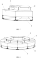
- the individual backward bent duct structures can in an illustrative example not according to the invention each be rectangular (as shown in FIGS. 1 to 3 ) or fan-shaped (as shown in FIGS. 6 to 7 and according to the invention) and are each formed by splicing baffle plates together.
- the baffle plates can be connected with each other via bolts, and connecting gaskets can be arranged therebetween.
- the bolts include bolts arranged in the lateral direction and bolts arranged at the bottom.
- the bolts arranged in the lateral direction can enable limitation in the horizontal plane range, and the bolts located at the bottom of the bent duct can limit vertical oscillation between the bent ducts.
- the individual backward bent duct structure includes a bent duct and a floating body 3.
- the floating body 3 can be of a box-type structure, and counterweight is additionally arranged in the floating body 3 to adjust a position relative to the water surface; or the floating body 3 is made of a light material.
- the floating body 3 is used for providing buoyancy, so that the whole device can float on the water surface with certain draught.
- the bent duct includes a vertical section of the bent duct 2 and a horizontal section of the bent duct 1 which communicate with each other.
- a horizontal opening of the horizontal section of the bent duct 1 is used for collecting waves, and the air chamber is formed in the vertical section of the bent duct 2.
- the waves impact air in the air chamber to form oscillation after entering the horizontal section 1. And, the oscillating air impacts the air turbine, so that the air turbine is enabled to do work to generate electricity.
- the floating body 3 is connected to an upper part of the horizontal section 1 and can be connected by adopting conventional rigid body connecting structures, such as connecting frameworks, positioning grooves, screws, tenons and matched mortises. A size of the floating body 3 is correspondingly adjusted according to requirement of the draught.
- the individual backward bent duct structures are connected on the side faces, bolts can also be adopted for their connection, and the connection position therebetween can be the same as the arrangement position of the bolts of a single individual backward bent duct structure.
- the individual backward bent duct structures can be directly assembled on the basis of the baffle plates to form the power generation unit using wave energy. It needs to be noted that the adjacent vertical sections 2 communicate with each other to form a connected air chamber.
- the vertical section 2 of one of the individual backward bent duct structures is connected with an air chamber pipeline 4, and an air turbine is arranged in the air chamber pipeline 4.
- the air turbine can be an impulse turbine, a Wells turbine and the like, and a generator, a storage battery and other devices are mounted at a rear end of the air turbine.
- Adjacent horizontal sections 1 may not communicate with each other.
- a partition plate is arranged between the adjacent horizontal sections 1. The partition plates play a role in rectifying a flow direction of water flow in the horizontal sections 1, so that the flow direction is mostly in a wave crest line direction, which is more advantageous in converting wave energy into air kinetic energy.
- a number of the individual backward bent duct structures in the power generation unit using wave energy cannot be too large.
- the air chamber pipeline 4 can be arranged in a vertical direction or in a horizontal direction and can be arranged inside the vertical section 2 or outside the vertical section 2, according to design requirements. In a word, as long as the air chamber pipeline 4 can communicate with the air chamber of the vertical section 2.
- a plurality of individual backward bent duct structures are connected together, so that vertical sections 2 communicate with each other.
- a group of power generation units using wave energy can share the air chamber to do work on the same air turbine, so that the flow rate of reciprocating airflow in the air chamber can be increased, the utilization efficiency of wave energy can be remarkably improved, and the installed capacity can be improved.
- the air chamber pipeline 4 can be in a same direction with the horizontal section 1. That is, the air chamber pipeline 4 can be perpendicular to the vertical section 2. Meanwhile, the air chamber pipeline 4 is a section of pipeline connected to the vertical section 2 and extended outward. In order to guide the airflow into the air chamber pipeline 4, the baffle plate is required to be mounted on the top of the vertical section 2. Moreover, a diameter of the air chamber pipeline 4 can be smaller than an inner diameter of the vertical section 2, so that an impact force of air in the air chamber on the air turbine in the air chamber pipeline 4 can be enhanced, the utilization efficiency of wave energy can be improved, and the installed capacity can be improved.
- the air chamber pipeline 4 can be installed on an upper part of the floating body 3 and can be supported by the floating body 3, so as to ensure the stability of the installation structure of the air chamber pipeline 4 and prevent the reliability of the whole structure from being affected by vibration.
- a cross section of the horizontal section 1 is fan-shaped, which forms an open horizontal section 1 to increase the size of the inlet. So, the collected wave flow is larger.
- the wave flow gradually flows towards the vertical section 2 along the horizontal section 1.
- the pressure intensity of wave energy can be increased along with the gradual reduction of the inner diameter of the horizontal section 1, and a space of the vertical section 2 can be filled in a larger range.
- the air chamber of the vertical section 2 can be squeezed and oscillated by filled waves to generate powerful air oscillation, which can better push the air turbine to perform work.
- the vertical section 2 can also be arranged to be of a fan-shaped structure, and a connected portion of the vertical section 2 which communicate with the horizontal section 1 should be in smooth transition to prevent the water flow and airflow from being obstructed.
- the floating bodies 3 of different individual backward bent duct structures can be independently arranged and can be connected into a whole after the individual backward bent duct structures are connected into a power generation unit using wave energy. Or, a whole floating body 3 is directly used.
- the present invention provides a power generation device using wave energy to which the power generation units using wave energy described above can be applied.
- a plurality of power generation units using wave energy are connected into a ring (as shown in FIG. 5 , not according to the invention, and FIG. 8 according to the invention) or a polygon (as shown in FIG. 4 , not according to the invention).
- Most of the aquaculture net cages are cylindrical or quadrangular. Quadrangular or annular power generation device using wave energy can be combined with existing open-sea production and life equipment to supply power to the aquaculture net cages.
- the power generation device using wave energy is combined with a wind driven generator pile foundation on the deep sea (used for coupling wind energy and wave energy)
- a scheme of the triangular power generation device using wave energy array can be applied.
- the guarantee of energy supply is an important part.
- the research and development of wave energy was mainly used for independent power supply equipment on the sea, the power generation capacity cannot meet the power utilization requirement due to the limitation of the size of the device.
- a mode of the device with the scattered-point array is generally adopted.
- the individual backward bent duct structure When the individual backward bent duct structure is independently applied, the individual backward bent duct structure has six-degree-of-freedom movement under the action of wave force, and the scattered-point type array is not beneficial to energy capture of a rear-row device due to the shielding effect.
- a plurality of power generation units using wave energy are connected into a ring or a polygon to form a compact array with a certain topological structure, so that the shielding effect can be avoided, and the movement of the power generation device using wave energy and the wave movement can generate resonance effect by reasonably arranging the array number of the power generation units using wave energy, which can obviously improve the overall performance of the device with arrays.
- each annular and polygonal power generation device using wave energy needs to be specifically designed according to application scenes and resonance conditions because of different sea areas where the device arranged, different sea wave conditions and different coupling resonance conditions with the equipment.
- the whole power generation device using wave energy is of a blocked type assembly structure (modularization is formed)
- the topological structure, the number of arrays, the number of turbines and the like can be flexibly arranged according to the requirements of the commissioning places, the service positions and the demands for electricity consumption.
- the connection can be achieved by bolts, and the connection mode can refer to the connection mode of the power generation units using wave energy.
- the power generation units using wave energy that are formed by the fan-shaped backward bent duct structures according to the invention can be directly connected to form an annular structure.
- connecting sections 5 need to be arranged at bent corners to form arc transition.
- the connecting section 5 can be used as the floating body 3 and can also be used for an integrated power supply device of a rear-end air turbine. Therefore, the whole structure can be assembled, and is compact in structure and convenient to be installed and disassembled.
- the device can be used immediately after being put into use, the device can be disassembled many times, and the device has the ability to be used continuously.
- the connecting section 5 can be a connecting corner and is made of a material which is the same as that of the floating body 3. After the connecting section 5 is applied, the buoyancy distribution of the power generation device using wave energy can be balanced, and the number and the size of the floating bodies 3 can be reduced.
- the power generation device using wave energy can be formed by assembling a plurality of power generation units using wave energy which can share anchor points therebetween, and a mooring mode is reasonably arranged, so that the commissioning cost can be reduced.
- the present invention also provides a power generation method of a power generation device using wave energy which can use the power generation device using wave energy according to the invention as described hereinbefore, including the following steps.
- step 1 under predetermined wave conditions, draught of the power generation device using wave energy are adjusted by replacing different floating bodies 3 (by replacing floating bodies 3 with different sizes or different materials or adjusting the size of counterweight in the floating body 3), and wave heights of the wave movement in an air chamber which are corresponding to different draught can be measured.
- step 2 the measured wave heights of the wave movement are compared with each other, and the draught corresponding to a maximum wave height of the wave movement is selected,
- step 3 the power generation device using wave energy is installed and placed in the sea based on the selected draught, and wave energy is used for power generation.
- the present invention provides a thought for improving the utilization efficiency of wave energy by forming resonance, and changes such a mode that in the prior art that only an individual backward bent duct structure is improved and the number of scattered arrays of the backward bent duct structures is increased to enhance the generating capacity. And, the maximum movement wave height of the water surface in the air chamber is obtained in a process that parameter optimization is performed on the power generation device using wave energy. In turn, the optimal use conditions of the device can be achieved by improving relevant parameters, so that the utilization efficiency of wave energy can be improved.
- the wave heights of the wave movement are measured according to a low-density draught spacing firstly, and a section of wave heights of the wave movement which has relatively larger wave heights is selected.
- the section of wave heights of the wave movement is measured based on a high-density draught spacing to obtain the draught which is corresponding to the maximum wave movement height.
- parameters including an opening direction of the air chamber, an opening size of the air chamber, a sectional area size of the air chamber, a length of the bent duct and an opening sectional area of the bent duct can be optimized to obtain an optimal resonance effect.
- the present invention provides a specific optimization embodiment. Under certain wave conditions, the optimal parameters of the individual backward bent duct structures are found by researching the parameters of the individual backward bent duct structures.
- a maximum energy conversion is taken as the target of the individual backward bent duct structures.
- the optimal draught of the individual backward bent duct structures is obtained by measurement and calculation. which guides selection of the material of the floating body 3, counterweight of the individual backward bent duct structure and the like in practical application.
- the wave conditions in the embodiment refer to wave conditions of the sea area in Qingdao area of China.
- a length of the individual backward bent duct structure is designed to be 13.6 m
- a width of the individual backward bent duct structure is designed to be 6.4 m
- a height of the individual backward bent duct structure is designed to be 10.4 m.
- a length of the horizontal section 1 is 13.6 m
- a length of the vertical section 2 is 10.4 m.
- the individual backward bent duct structure not according to the invention is rectangular pipe with a length-width ratio of 2:1. That is, a length of a section of the rectangular pipe is 6.4 m, and a width thereof is 3.2 m.
- a cuboid floating body 3 with the size of 7.2 m ⁇ 10.4 m ⁇ 6.4 m is arranged.
- a scale of the numerical model is selected to be 1:16 through a numerical calculation method under the Froude similarity criterion.
- a prototype wave conditions are that the wave height is 2 m and the period is 7s.
- the numerical calculation wave conditions are that the wave height is 0.12 m and the period is 1.75 s under this similar criterion.
- the draft position of the individual backward bent duct structure is changed, and a distance between a bottom of a front wall of the device and the water surface is taken as the draught.
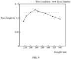
- the corresponding conditions of the wave heights of the wave movement in the air chamber of the device are researched under the conditions that the draught is 0.215 m, 0.240 m, 0.265 m, 0.290 m, 0.315 m and 0.340 m respectively. It can be seen that under the condition that the draft of the individual backward bent duct structure is 0.240-0.265 m, the response intensity of the wave movement in the air chamber is larger, and the movement amplitude of the water surface in the air chamber is higher than the movement amplitude of a water surface in a wave field.
- a curve of the relationship between the draught of the individual body backward bent duct structure and the wave height can be shown, thereby obtaining an optimal draught of 0.255 m.
- the method can be used for guiding design and manufacture of an array structure of a later power generation device using wave energy.
Landscapes
- Engineering & Computer Science (AREA)
- Chemical & Material Sciences (AREA)
- Combustion & Propulsion (AREA)
- Mechanical Engineering (AREA)
- General Engineering & Computer Science (AREA)
- Other Liquid Machine Or Engine Such As Wave Power Use (AREA)
Claims (9)
- Unité de génération de puissance utilisant de l'énergie des vagues, comprenant une pluralité de structures à conduit courbé vers l'arrière individuelles connectées en parallèle, chacune de la pluralité des structures à conduit courbé vers l'arrière individuelles comprenant un conduit courbé et un corps flottant (3), le conduit courbé comprenant une section verticale (2) du conduit courbé et une section horizontale (1) du conduit courbé, une partie supérieure de la section horizontale (1) du conduit courbé étant connectée au corps flottant (3), la section verticale (2) communiquant avec une autre section verticale du conduit courbé qui est adjacente à la section verticale (2), la section verticale (2) du conduit courbé d'une de la pluralité de structures à conduit courbé vers l'arrière individuelles étant connectée à une canalisation (4) de chambre à air, et une turbine à air étant agencée dans la canalisation (4) de chambre à air,
caractérisée en ce que
une section transversale de la section horizontale (1) du conduit courbé est en forme de ventilateur pour former une section horizontale ouverte, et une dimension interne de la section horizontale (1) diminue graduellement vers un centre de la section horizontale (1). - Unité de génération de puissance utilisant de l'énergie des vagues selon la revendication 1, la canalisation (4) de chambre à air étant dans une même direction que la section horizontale (1) du conduit courbé, et étant située dans une partie supérieure du corps flottant (3).
- Unité de génération de puissance utilisant de l'énergie des vagues selon la revendication 1, le corps flottant (3) étant connecté avec des corps flottants d'autres de la pluralité de structures à conduit courbé vers l'arrière individuelles en un tout.
- Dispositif de génération de puissance utilisant de l'énergie des vagues, comprenant une pluralité d'unités de génération de puissance utilisant de l'énergie des vagues selon l'une quelconque des revendications 1 à 2, et la pluralité d'unités de génération de puissance utilisant de l'énergie des vagues étant connectées en anneau ou en polygone.
- Dispositif de génération de puissance utilisant de l'énergie des vagues selon la revendication 4, pour chacune de la pluralité d'unités de génération de puissance utilisant de l'énergie des vagues, l'unité de génération de puissance étant directement connectée à une autre unité de génération de puissance de la pluralité d'unités de génération de puissance utilisant de l'énergie des vagues qui est adjacente à l'unité de génération de puissance, ou étant connectée à l'autre unité de génération de puissance via une section de connexion (5).
- Dispositif de génération de puissance utilisant de l'énergie des vagues selon la revendication 5, la section de connexion (5) étant un coin de connexion, et ayant un même matériau que le corps flottant (3).
- Procédé de génération de puissance d'un dispositif de génération de puissance utilisant de l'énergie des vagues selon la revendication 4, le procédé comprenant :sous des conditions de vagues prédéterminées, l'ajustement d'un tirant d'eau du dispositif de génération de puissance utilisant de l'énergie des vagues, et la mesure de hauteurs de vagues d'un mouvement de vagues dans une chambre à air qui correspondent à différents tirants d'eau respectivement ;la comparaison des hauteurs de vagues du mouvement de vagues après avoir été mesurées les unes avec les autres, et la sélection du tirant d'eau qui correspond à une hauteur maximale des hauteurs de vagues du mouvement de vagues ; etl'installation du dispositif de génération de puissance utilisant de l'énergie des vagues sur la base du tirant d'eau après avoir été sélectionné, et la génération de puissance en utilisant de l'énergie des vagues.
- Procédé de génération de puissance du dispositif de génération de puissance utilisant de l'énergie des vagues selon la revendication 7, comprenant : lorsque le tirant d'eau est ajusté,la mesure des hauteurs de vagues du mouvement de vagues sur la base d'un espacement de tirant d'eau basse densité, et la sélection d'une section des hauteurs de vagues du mouvement de vagues qui a des hauteurs de vagues relativement plus grandes ; etla mesure de la section des hauteurs de vagues du mouvement de vagues sur la base d'un espacement de tirant d'eau haute densité, et l'obtention du tirant d'eau qui correspond à la hauteur maximale des hauteurs de vagues du mouvement de vagues.
- Procédé de génération de puissance du dispositif de génération de puissance utilisant de l'énergie des vagues selon la revendication 7 ou 8, comprenant en outre
l'optimisation de paramètres comprenant une direction d'ouverture de la chambre à air, une taille d'ouverture de la chambre à air, une taille de section en coupe transversale de la chambre à air, une longueur du conduit courbé et une section en coupe transversale d'ouverture du conduit courbé.
Applications Claiming Priority (2)
| Application Number | Priority Date | Filing Date | Title |
|---|---|---|---|
| CN202110719557.0A CN113266515B (zh) | 2021-06-28 | 2021-06-28 | 一种波能发电单元及其波能发电装置和波能发电方法 |
| PCT/CN2021/136791 WO2023273174A1 (fr) | 2021-06-28 | 2021-12-09 | Unité de production d'énergie houlomotrice et dispositif de production d'énergie houlomotrice le comprenant, et procédé de production d'énergie houlomotrice d'un dispositif de production d'énergie houlomotrice |
Publications (3)
| Publication Number | Publication Date |
|---|---|
| EP4134541A4 EP4134541A4 (fr) | 2023-02-15 |
| EP4134541A1 EP4134541A1 (fr) | 2023-02-15 |
| EP4134541B1 true EP4134541B1 (fr) | 2024-07-31 |
Family
ID=77236073
Family Applications (1)
| Application Number | Title | Priority Date | Filing Date |
|---|---|---|---|
| EP21867910.8A Active EP4134541B1 (fr) | 2021-06-28 | 2021-12-09 | Unité de production d'énergie houlomotrice et dispositif de production d'énergie houlomotrice le comprenant, et procédé de production d'énergie houlomotrice d'un dispositif de production d'énergie houlomotrice |
Country Status (3)
| Country | Link |
|---|---|
| EP (1) | EP4134541B1 (fr) |
| CN (1) | CN113266515B (fr) |
| WO (1) | WO2023273174A1 (fr) |
Families Citing this family (8)
| Publication number | Priority date | Publication date | Assignee | Title |
|---|---|---|---|---|
| CN113266515B (zh) * | 2021-06-28 | 2026-04-17 | 中国海洋大学 | 一种波能发电单元及其波能发电装置和波能发电方法 |
| CN115288921B (zh) * | 2022-08-12 | 2024-01-23 | 南方电网电力科技股份有限公司 | 一种波浪能发电转换单元阵列设计方法、系统及设备 |
| GB2632093A (en) * | 2023-07-06 | 2025-01-29 | Havkraft As | Ocean wave energy conversion apparatus and method |
| EP4600483A1 (fr) * | 2024-02-07 | 2025-08-13 | Frenesim Das Ondas, LDA | Convertisseur d'énergie à ondes de résonance multiples et procédé respectif de celui-ci |
| CN118327865B (zh) * | 2024-04-26 | 2025-02-25 | 清华大学 | 波浪能发电装置 |
| CN118375549B (zh) * | 2024-06-24 | 2024-09-06 | 集美大学 | 一种后弯管波浪能发电浮标及其空气透平控制装置和方法 |
| CN120387297B (zh) * | 2025-04-17 | 2025-10-17 | 中国海洋大学 | 一种波浪能装置全过程模型试验中相似准则的协调方法 |
| CN120867936B (zh) * | 2025-09-24 | 2025-12-26 | 湖南科技大学三亚研究院 | 一种浮式波浪能发电装置 |
Family Cites Families (12)
| Publication number | Priority date | Publication date | Assignee | Title |
|---|---|---|---|---|
| JPH068767U (ja) * | 1992-06-30 | 1994-02-04 | 株式会社緑星社 | 波力発電ブイ |
| JP3493130B2 (ja) * | 1998-04-10 | 2004-02-03 | 善雄 益田 | 波力発電装置 |
| EP2410170B1 (fr) * | 2006-10-20 | 2014-11-26 | Maritime Technologies Limited | Convertisseur d'énergie d'ondes flottables et procédé d'amélioration de l'efficacité d'un convertisseur d'énergie d'ondes flottables |
| KR101093448B1 (ko) * | 2011-07-15 | 2011-12-19 | 주식회사 유니크 | 오일 컨트롤 밸브 |
| US11644004B2 (en) * | 2016-10-17 | 2023-05-09 | Wave Swell Energy Limited | Apparatus and method for extracting energy from a fluid |
| CN107044379B (zh) | 2017-04-26 | 2019-08-02 | 中国科学院广州能源研究所 | 一种海上自航式绿色能源电力供应装置 |
| CN108425788B (zh) * | 2018-03-23 | 2020-04-10 | 中国科学院广州能源研究所 | 一种单向冲动式波浪能发电装置 |
| CN108644057B (zh) * | 2018-04-16 | 2019-08-02 | 浙江大学 | 一种防波堤兼双气室振荡水柱发电装置 |
| CN109236549B (zh) * | 2018-11-28 | 2020-12-22 | 北京驭海能源技术中心(有限合伙) | 一种高效波浪能发电装置 |
| CN112943515A (zh) * | 2021-01-06 | 2021-06-11 | 南京工程学院 | 一种带有空气蓄能器的漂浮振荡水柱式波浪能发电装置 |
| CN113266515B (zh) * | 2021-06-28 | 2026-04-17 | 中国海洋大学 | 一种波能发电单元及其波能发电装置和波能发电方法 |
| CN215170508U (zh) * | 2021-06-28 | 2021-12-14 | 中国海洋大学 | 一种波能发电单元及其波能发电装置 |
-
2021
- 2021-06-28 CN CN202110719557.0A patent/CN113266515B/zh active Active
- 2021-12-09 EP EP21867910.8A patent/EP4134541B1/fr active Active
- 2021-12-09 WO PCT/CN2021/136791 patent/WO2023273174A1/fr not_active Ceased
Also Published As
| Publication number | Publication date |
|---|---|
| WO2023273174A1 (fr) | 2023-01-05 |
| CN113266515A (zh) | 2021-08-17 |
| CN113266515B (zh) | 2026-04-17 |
| EP4134541A4 (fr) | 2023-02-15 |
| EP4134541A1 (fr) | 2023-02-15 |
Similar Documents
| Publication | Publication Date | Title |
|---|---|---|
| EP4134541B1 (fr) | Unité de production d'énergie houlomotrice et dispositif de production d'énergie houlomotrice le comprenant, et procédé de production d'énergie houlomotrice d'un dispositif de production d'énergie houlomotrice | |
| CN112855449B (zh) | 一种半潜式海上风能和波浪能组合发电装置 | |
| US10947952B2 (en) | Floating wind-wave integrated power generation system | |
| CN103225315A (zh) | 一种由单桩、筒形基础和锚索组成的海上风电基础 | |
| CN105422376A (zh) | 垂直导桩式浮防波堤兼波浪能发电装置 | |
| CN201941953U (zh) | 海上组合式漂浮风力发电平台 | |
| WO2022161127A1 (fr) | Bouée marine destinée à la production et à l'alimentation en énergie complémentaire à l'aide d'énergie solaire, éolienne et marémotrice et procédé associé | |
| CN108867545A (zh) | 一种集成振荡水柱与浮子发电的防波堤系统 | |
| Liu et al. | Hydrodynamic and energy-harvesting performance of an isolated oscillating water column device: An experimental study | |
| CN217115953U (zh) | 一种融合海洋能、光伏与风能的海上发电装置 | |
| CN113335467A (zh) | 一种基于波浪能和太阳能组合发电的海洋浮式平台 | |
| CN110985279B (zh) | 一种月池型多模块波浪能发电系统 | |
| CN212373618U (zh) | 中等深度水域的浮式风机装备 | |
| CN215170508U (zh) | 一种波能发电单元及其波能发电装置 | |
| CN217206714U (zh) | 一种海上多能源互补发电集成系统 | |
| US11753786B2 (en) | Fixed permeable breakwater doubling as wave energy generating device | |
| CN214533359U (zh) | 一种基于漂浮式平台的风浪耦合利用装置 | |
| CN119778139A (zh) | 一种近岸波能聚焦—波生流联合发电消波装置 | |
| CN117072365B (zh) | 一种波浪能发电装置和海洋牧场 | |
| CN113911273A (zh) | 一种海上驳船式风力机加装网箱的深海发电养殖系统 | |
| CN118775153A (zh) | 场域融合式的海上漂浮式风浪联合发电装置 | |
| JP6138776B2 (ja) | 波エネルギー吸収ユニット | |
| CN212336078U (zh) | 一种单桩式风机和张紧式网箱结构的综合开发装置 | |
| KR101666104B1 (ko) | 동요 저감용 댐퍼가 구비된 부유체 | |
| CN222391509U (zh) | 海上组合发电装置 |
Legal Events
| Date | Code | Title | Description |
|---|---|---|---|
| STAA | Information on the status of an ep patent application or granted ep patent |
Free format text: STATUS: UNKNOWN |
|
| STAA | Information on the status of an ep patent application or granted ep patent |
Free format text: STATUS: THE INTERNATIONAL PUBLICATION HAS BEEN MADE |
|
| PUAI | Public reference made under article 153(3) epc to a published international application that has entered the european phase |
Free format text: ORIGINAL CODE: 0009012 |
|
| STAA | Information on the status of an ep patent application or granted ep patent |
Free format text: STATUS: REQUEST FOR EXAMINATION WAS MADE |
|
| 17P | Request for examination filed |
Effective date: 20220324 |
|
| A4 | Supplementary search report drawn up and despatched |
Effective date: 20221207 |
|
| AK | Designated contracting states |
Kind code of ref document: A1 Designated state(s): AL AT BE BG CH CY CZ DE DK EE ES FI FR GB GR HR HU IE IS IT LI LT LU LV MC MK MT NL NO PL PT RO RS SE SI SK SM TR |
|
| STAA | Information on the status of an ep patent application or granted ep patent |
Free format text: STATUS: EXAMINATION IS IN PROGRESS |
|
| 17Q | First examination report despatched |
Effective date: 20230922 |
|
| GRAP | Despatch of communication of intention to grant a patent |
Free format text: ORIGINAL CODE: EPIDOSNIGR1 |
|
| STAA | Information on the status of an ep patent application or granted ep patent |
Free format text: STATUS: GRANT OF PATENT IS INTENDED |
|
| DAV | Request for validation of the european patent (deleted) | ||
| DAX | Request for extension of the european patent (deleted) | ||
| INTG | Intention to grant announced |
Effective date: 20240417 |
|
| GRAS | Grant fee paid |
Free format text: ORIGINAL CODE: EPIDOSNIGR3 |
|
| GRAA | (expected) grant |
Free format text: ORIGINAL CODE: 0009210 |
|
| STAA | Information on the status of an ep patent application or granted ep patent |
Free format text: STATUS: THE PATENT HAS BEEN GRANTED |
|
| AK | Designated contracting states |
Kind code of ref document: B1 Designated state(s): AL AT BE BG CH CY CZ DE DK EE ES FI FR GB GR HR HU IE IS IT LI LT LU LV MC MK MT NL NO PL PT RO RS SE SI SK SM TR |
|
| REG | Reference to a national code |
Ref country code: CH Ref legal event code: EP Ref country code: GB Ref legal event code: FG4D |
|
| REG | Reference to a national code |
Ref country code: DE Ref legal event code: R096 Ref document number: 602021016614 Country of ref document: DE |
|
| REG | Reference to a national code |
Ref country code: IE Ref legal event code: FG4D |
|
| REG | Reference to a national code |
Ref country code: LT Ref legal event code: MG9D |
|
| REG | Reference to a national code |
Ref country code: NL Ref legal event code: MP Effective date: 20240731 |
|
| PG25 | Lapsed in a contracting state [announced via postgrant information from national office to epo] |
Ref country code: PT Free format text: LAPSE BECAUSE OF FAILURE TO SUBMIT A TRANSLATION OF THE DESCRIPTION OR TO PAY THE FEE WITHIN THE PRESCRIBED TIME-LIMIT Effective date: 20241202 |
|
| REG | Reference to a national code |
Ref country code: AT Ref legal event code: MK05 Ref document number: 1708666 Country of ref document: AT Kind code of ref document: T Effective date: 20240731 |
|
| PG25 | Lapsed in a contracting state [announced via postgrant information from national office to epo] |
Ref country code: PT Free format text: LAPSE BECAUSE OF FAILURE TO SUBMIT A TRANSLATION OF THE DESCRIPTION OR TO PAY THE FEE WITHIN THE PRESCRIBED TIME-LIMIT Effective date: 20241202 |
|
| PG25 | Lapsed in a contracting state [announced via postgrant information from national office to epo] |
Ref country code: NO Free format text: LAPSE BECAUSE OF FAILURE TO SUBMIT A TRANSLATION OF THE DESCRIPTION OR TO PAY THE FEE WITHIN THE PRESCRIBED TIME-LIMIT Effective date: 20241031 |
|
| PG25 | Lapsed in a contracting state [announced via postgrant information from national office to epo] |
Ref country code: NL Free format text: LAPSE BECAUSE OF FAILURE TO SUBMIT A TRANSLATION OF THE DESCRIPTION OR TO PAY THE FEE WITHIN THE PRESCRIBED TIME-LIMIT Effective date: 20240731 Ref country code: FI Free format text: LAPSE BECAUSE OF FAILURE TO SUBMIT A TRANSLATION OF THE DESCRIPTION OR TO PAY THE FEE WITHIN THE PRESCRIBED TIME-LIMIT Effective date: 20240731 Ref country code: PL Free format text: LAPSE BECAUSE OF FAILURE TO SUBMIT A TRANSLATION OF THE DESCRIPTION OR TO PAY THE FEE WITHIN THE PRESCRIBED TIME-LIMIT Effective date: 20240731 Ref country code: GR Free format text: LAPSE BECAUSE OF FAILURE TO SUBMIT A TRANSLATION OF THE DESCRIPTION OR TO PAY THE FEE WITHIN THE PRESCRIBED TIME-LIMIT Effective date: 20241101 |
|
| PG25 | Lapsed in a contracting state [announced via postgrant information from national office to epo] |
Ref country code: BG Free format text: LAPSE BECAUSE OF FAILURE TO SUBMIT A TRANSLATION OF THE DESCRIPTION OR TO PAY THE FEE WITHIN THE PRESCRIBED TIME-LIMIT Effective date: 20240731 |
|
| PG25 | Lapsed in a contracting state [announced via postgrant information from national office to epo] |
Ref country code: LV Free format text: LAPSE BECAUSE OF FAILURE TO SUBMIT A TRANSLATION OF THE DESCRIPTION OR TO PAY THE FEE WITHIN THE PRESCRIBED TIME-LIMIT Effective date: 20240731 |
|
| PG25 | Lapsed in a contracting state [announced via postgrant information from national office to epo] |
Ref country code: IS Free format text: LAPSE BECAUSE OF FAILURE TO SUBMIT A TRANSLATION OF THE DESCRIPTION OR TO PAY THE FEE WITHIN THE PRESCRIBED TIME-LIMIT Effective date: 20241130 Ref country code: AT Free format text: LAPSE BECAUSE OF FAILURE TO SUBMIT A TRANSLATION OF THE DESCRIPTION OR TO PAY THE FEE WITHIN THE PRESCRIBED TIME-LIMIT Effective date: 20240731 |
|
| PG25 | Lapsed in a contracting state [announced via postgrant information from national office to epo] |
Ref country code: HR Free format text: LAPSE BECAUSE OF FAILURE TO SUBMIT A TRANSLATION OF THE DESCRIPTION OR TO PAY THE FEE WITHIN THE PRESCRIBED TIME-LIMIT Effective date: 20240731 |
|
| PG25 | Lapsed in a contracting state [announced via postgrant information from national office to epo] |
Ref country code: ES Free format text: LAPSE BECAUSE OF FAILURE TO SUBMIT A TRANSLATION OF THE DESCRIPTION OR TO PAY THE FEE WITHIN THE PRESCRIBED TIME-LIMIT Effective date: 20240731 Ref country code: RS Free format text: LAPSE BECAUSE OF FAILURE TO SUBMIT A TRANSLATION OF THE DESCRIPTION OR TO PAY THE FEE WITHIN THE PRESCRIBED TIME-LIMIT Effective date: 20241031 |
|
| PG25 | Lapsed in a contracting state [announced via postgrant information from national office to epo] |
Ref country code: RS Free format text: LAPSE BECAUSE OF FAILURE TO SUBMIT A TRANSLATION OF THE DESCRIPTION OR TO PAY THE FEE WITHIN THE PRESCRIBED TIME-LIMIT Effective date: 20241031 Ref country code: PL Free format text: LAPSE BECAUSE OF FAILURE TO SUBMIT A TRANSLATION OF THE DESCRIPTION OR TO PAY THE FEE WITHIN THE PRESCRIBED TIME-LIMIT Effective date: 20240731 Ref country code: NO Free format text: LAPSE BECAUSE OF FAILURE TO SUBMIT A TRANSLATION OF THE DESCRIPTION OR TO PAY THE FEE WITHIN THE PRESCRIBED TIME-LIMIT Effective date: 20241031 Ref country code: NL Free format text: LAPSE BECAUSE OF FAILURE TO SUBMIT A TRANSLATION OF THE DESCRIPTION OR TO PAY THE FEE WITHIN THE PRESCRIBED TIME-LIMIT Effective date: 20240731 Ref country code: LV Free format text: LAPSE BECAUSE OF FAILURE TO SUBMIT A TRANSLATION OF THE DESCRIPTION OR TO PAY THE FEE WITHIN THE PRESCRIBED TIME-LIMIT Effective date: 20240731 Ref country code: IS Free format text: LAPSE BECAUSE OF FAILURE TO SUBMIT A TRANSLATION OF THE DESCRIPTION OR TO PAY THE FEE WITHIN THE PRESCRIBED TIME-LIMIT Effective date: 20241130 Ref country code: HR Free format text: LAPSE BECAUSE OF FAILURE TO SUBMIT A TRANSLATION OF THE DESCRIPTION OR TO PAY THE FEE WITHIN THE PRESCRIBED TIME-LIMIT Effective date: 20240731 Ref country code: GR Free format text: LAPSE BECAUSE OF FAILURE TO SUBMIT A TRANSLATION OF THE DESCRIPTION OR TO PAY THE FEE WITHIN THE PRESCRIBED TIME-LIMIT Effective date: 20241101 Ref country code: FI Free format text: LAPSE BECAUSE OF FAILURE TO SUBMIT A TRANSLATION OF THE DESCRIPTION OR TO PAY THE FEE WITHIN THE PRESCRIBED TIME-LIMIT Effective date: 20240731 Ref country code: ES Free format text: LAPSE BECAUSE OF FAILURE TO SUBMIT A TRANSLATION OF THE DESCRIPTION OR TO PAY THE FEE WITHIN THE PRESCRIBED TIME-LIMIT Effective date: 20240731 Ref country code: BG Free format text: LAPSE BECAUSE OF FAILURE TO SUBMIT A TRANSLATION OF THE DESCRIPTION OR TO PAY THE FEE WITHIN THE PRESCRIBED TIME-LIMIT Effective date: 20240731 Ref country code: AT Free format text: LAPSE BECAUSE OF FAILURE TO SUBMIT A TRANSLATION OF THE DESCRIPTION OR TO PAY THE FEE WITHIN THE PRESCRIBED TIME-LIMIT Effective date: 20240731 |
|
| PG25 | Lapsed in a contracting state [announced via postgrant information from national office to epo] |
Ref country code: SM Free format text: LAPSE BECAUSE OF FAILURE TO SUBMIT A TRANSLATION OF THE DESCRIPTION OR TO PAY THE FEE WITHIN THE PRESCRIBED TIME-LIMIT Effective date: 20240731 Ref country code: DK Free format text: LAPSE BECAUSE OF FAILURE TO SUBMIT A TRANSLATION OF THE DESCRIPTION OR TO PAY THE FEE WITHIN THE PRESCRIBED TIME-LIMIT Effective date: 20240731 Ref country code: RO Free format text: LAPSE BECAUSE OF FAILURE TO SUBMIT A TRANSLATION OF THE DESCRIPTION OR TO PAY THE FEE WITHIN THE PRESCRIBED TIME-LIMIT Effective date: 20240731 |
|
| PG25 | Lapsed in a contracting state [announced via postgrant information from national office to epo] |
Ref country code: EE Free format text: LAPSE BECAUSE OF FAILURE TO SUBMIT A TRANSLATION OF THE DESCRIPTION OR TO PAY THE FEE WITHIN THE PRESCRIBED TIME-LIMIT Effective date: 20240731 |
|
| PG25 | Lapsed in a contracting state [announced via postgrant information from national office to epo] |
Ref country code: CZ Free format text: LAPSE BECAUSE OF FAILURE TO SUBMIT A TRANSLATION OF THE DESCRIPTION OR TO PAY THE FEE WITHIN THE PRESCRIBED TIME-LIMIT Effective date: 20240731 |
|
| PG25 | Lapsed in a contracting state [announced via postgrant information from national office to epo] |
Ref country code: SK Free format text: LAPSE BECAUSE OF FAILURE TO SUBMIT A TRANSLATION OF THE DESCRIPTION OR TO PAY THE FEE WITHIN THE PRESCRIBED TIME-LIMIT Effective date: 20240731 Ref country code: IT Free format text: LAPSE BECAUSE OF FAILURE TO SUBMIT A TRANSLATION OF THE DESCRIPTION OR TO PAY THE FEE WITHIN THE PRESCRIBED TIME-LIMIT Effective date: 20240731 |
|
| REG | Reference to a national code |
Ref country code: DE Ref legal event code: R097 Ref document number: 602021016614 Country of ref document: DE |
|
| PLBE | No opposition filed within time limit |
Free format text: ORIGINAL CODE: 0009261 |
|
| STAA | Information on the status of an ep patent application or granted ep patent |
Free format text: STATUS: NO OPPOSITION FILED WITHIN TIME LIMIT |
|
| REG | Reference to a national code |
Ref country code: DE Ref legal event code: R119 Ref document number: 602021016614 Country of ref document: DE |
|
| PG25 | Lapsed in a contracting state [announced via postgrant information from national office to epo] |
Ref country code: MC Free format text: LAPSE BECAUSE OF FAILURE TO SUBMIT A TRANSLATION OF THE DESCRIPTION OR TO PAY THE FEE WITHIN THE PRESCRIBED TIME-LIMIT Effective date: 20240731 |
|
| 26N | No opposition filed |
Effective date: 20250501 |
|
| REG | Reference to a national code |
Ref country code: CH Ref legal event code: PL |
|
| PG25 | Lapsed in a contracting state [announced via postgrant information from national office to epo] |
Ref country code: LU Free format text: LAPSE BECAUSE OF NON-PAYMENT OF DUE FEES Effective date: 20241209 |
|
| PG25 | Lapsed in a contracting state [announced via postgrant information from national office to epo] |
Ref country code: SE Free format text: LAPSE BECAUSE OF FAILURE TO SUBMIT A TRANSLATION OF THE DESCRIPTION OR TO PAY THE FEE WITHIN THE PRESCRIBED TIME-LIMIT Effective date: 20240731 |
|
| REG | Reference to a national code |
Ref country code: BE Ref legal event code: MM Effective date: 20241231 |
|
| PG25 | Lapsed in a contracting state [announced via postgrant information from national office to epo] |
Ref country code: DE Free format text: LAPSE BECAUSE OF NON-PAYMENT OF DUE FEES Effective date: 20250701 |
|
| PG25 | Lapsed in a contracting state [announced via postgrant information from national office to epo] |
Ref country code: BE Free format text: LAPSE BECAUSE OF NON-PAYMENT OF DUE FEES Effective date: 20241231 |
|
| PG25 | Lapsed in a contracting state [announced via postgrant information from national office to epo] |
Ref country code: FR Free format text: LAPSE BECAUSE OF NON-PAYMENT OF DUE FEES Effective date: 20241231 |
|
| PG25 | Lapsed in a contracting state [announced via postgrant information from national office to epo] |
Ref country code: CH Free format text: LAPSE BECAUSE OF NON-PAYMENT OF DUE FEES Effective date: 20241231 |
|
| PG25 | Lapsed in a contracting state [announced via postgrant information from national office to epo] |
Ref country code: IE Free format text: LAPSE BECAUSE OF NON-PAYMENT OF DUE FEES Effective date: 20241209 |
|
| PGFP | Annual fee paid to national office [announced via postgrant information from national office to epo] |
Ref country code: GB Payment date: 20251127 Year of fee payment: 5 |