EP4134544A1 - Dichtungsvorrichtung und verfahren zur durchführung der wartung von windflügeln einer windenergieanlage in einer geschlossenen umgebung - Google Patents
Dichtungsvorrichtung und verfahren zur durchführung der wartung von windflügeln einer windenergieanlage in einer geschlossenen umgebung Download PDFInfo
- Publication number
- EP4134544A1 EP4134544A1 EP21191755.4A EP21191755A EP4134544A1 EP 4134544 A1 EP4134544 A1 EP 4134544A1 EP 21191755 A EP21191755 A EP 21191755A EP 4134544 A1 EP4134544 A1 EP 4134544A1
- Authority
- EP
- European Patent Office
- Prior art keywords
- blade
- sealing
- sealing device
- support band
- longitudinal
- Prior art date
- Legal status (The legal status is an assumption and is not a legal conclusion. Google has not performed a legal analysis and makes no representation as to the accuracy of the status listed.)
- Granted
Links
Images

Classifications
-
- F—MECHANICAL ENGINEERING; LIGHTING; HEATING; WEAPONS; BLASTING
- F03—MACHINES OR ENGINES FOR LIQUIDS; WIND, SPRING, OR WEIGHT MOTORS; PRODUCING MECHANICAL POWER OR A REACTIVE PROPULSIVE THRUST, NOT OTHERWISE PROVIDED FOR
- F03D—WIND MOTORS
- F03D80/00—Details, components or accessories not provided for in groups F03D1/00 - F03D17/00
- F03D80/50—Maintenance or repair
- F03D80/501—Maintenance or repair by using platforms
-
- F—MECHANICAL ENGINEERING; LIGHTING; HEATING; WEAPONS; BLASTING
- F03—MACHINES OR ENGINES FOR LIQUIDS; WIND, SPRING, OR WEIGHT MOTORS; PRODUCING MECHANICAL POWER OR A REACTIVE PROPULSIVE THRUST, NOT OTHERWISE PROVIDED FOR
- F03D—WIND MOTORS
- F03D80/00—Details, components or accessories not provided for in groups F03D1/00 - F03D17/00
- F03D80/50—Maintenance or repair
- F03D80/502—Maintenance or repair of rotors or blades
-
- F—MECHANICAL ENGINEERING; LIGHTING; HEATING; WEAPONS; BLASTING
- F05—INDEXING SCHEMES RELATING TO ENGINES OR PUMPS IN VARIOUS SUBCLASSES OF CLASSES F01-F04
- F05B—INDEXING SCHEME RELATING TO WIND, SPRING, WEIGHT, INERTIA OR LIKE MOTORS, TO MACHINES OR ENGINES FOR LIQUIDS COVERED BY SUBCLASSES F03B, F03D AND F03G
- F05B2230/00—Manufacture
- F05B2230/80—Repairing, retrofitting or upgrading methods
-
- F—MECHANICAL ENGINEERING; LIGHTING; HEATING; WEAPONS; BLASTING
- F05—INDEXING SCHEMES RELATING TO ENGINES OR PUMPS IN VARIOUS SUBCLASSES OF CLASSES F01-F04
- F05B—INDEXING SCHEME RELATING TO WIND, SPRING, WEIGHT, INERTIA OR LIKE MOTORS, TO MACHINES OR ENGINES FOR LIQUIDS COVERED BY SUBCLASSES F03B, F03D AND F03G
- F05B2240/00—Components
- F05B2240/57—Seals
-
- Y—GENERAL TAGGING OF NEW TECHNOLOGICAL DEVELOPMENTS; GENERAL TAGGING OF CROSS-SECTIONAL TECHNOLOGIES SPANNING OVER SEVERAL SECTIONS OF THE IPC; TECHNICAL SUBJECTS COVERED BY FORMER USPC CROSS-REFERENCE ART COLLECTIONS [XRACs] AND DIGESTS
- Y02—TECHNOLOGIES OR APPLICATIONS FOR MITIGATION OR ADAPTATION AGAINST CLIMATE CHANGE
- Y02E—REDUCTION OF GREENHOUSE GAS [GHG] EMISSIONS, RELATED TO ENERGY GENERATION, TRANSMISSION OR DISTRIBUTION
- Y02E10/00—Energy generation through renewable energy sources
- Y02E10/70—Wind energy
- Y02E10/72—Wind turbines with rotation axis in wind direction
Definitions
- the present disclosure relates to a sealing device and method that allows to perform wind blade maintenance, including repairs and inspection, in an enclosed environment, in particular having a floor, a wall and a roof for creating an enclosed environment.
- the interior area where blade maintenance and inspection are taking place can be isolated from water and entry of gases, thus creating a barrier to the exterior where humidity and temperature can be controlled.
- suspended platforms on the hub or suspended on a mobile crane, in which one or more operators are installed to perform the inspection, maintenance or repair. More recently, some of these suspended platforms include a habitat/tent to create an enclosed environment that cover the suspended platform on top with a roof on bottom with a floor (in some cases) and vertically with walls, to shelter the operator from the outside environment. These habitats tend to be flexible or rigid structures that cover the blade locally.
- the existing interface solutions between the habitat/tent and the blade are not air and watertight, jeopardizing the usage of this solution under rain, snow and other adverse weather conditions and the respective possibility to have an air conditioning system that allows to control humidity and temperature of the habitat's interior volume.
- Document GB2550842A discloses an apparatus comprising a temporary enclosure which isolates a small area of a blade surface which needs repair, where the enclosure has a transparent portion and includes holes through which the operator hands may access the work area. Due to the nature of the present disclosure can be suitable for exceedingly small repairs once the system design creates a barrier between the operator and the blade which highly restricts the operator accessibility to areas larger than 500x500 mm. The solution is designed to only sustain the weight of this light and small enclosure add-on. Furthermore, this apparatus cannot be used on curved shapes with low radius of curvature. The proposed sealing cross section is mentioned to be rigid and not to collapse due to vacuum forces, which renders it impossible to contour the curved shapes of a blade airfoil section.
- the sealing cross section has some kind of elasticity and is forced to curve, the circular cross section would immediately collapse under the existing bending forces and deform the shape of the sealing in such a way that the suction function would be lost due to the deformation of the flanges.
- the bore would restrain significantly the air flow on the system, or even be deformed in such a way that would choke it completely.
- the invention does not propose a credible solution to cover the trailing edge of the blade or how to avoid water ingression on that area.
- Document DE19909698A1 proposes a complete blade repair platform and habitat. It includes a solution for the interface between the habitat and the blade, using a hose that is pressed to the blade surface by means of sliding plungers actuated pneumatically, hydraulically, magnetically or electrically. This solution creates similar difficulties to the ones stated previous inventions. Furthermore, it is not clear how this system would accommodate differences on the blade airfoil shape. For example, when the blade cross section is close to a circle, it is not clear if and how the sliding plungers can accommodate the blade's large airfoil thicknesses.
- Document WO2020058099 presents a water intrusion prevention system to be mounted on a turbine blade.
- the solution proposed comprises a collar fixed to the blade by means of a tape or a similar component, and an umbrella-like membrane that is attached to this device. This attachment is performed under a tissue in excess to avoid water egression on the attachment line.
- the potential use of this solution can be compromised by the tape ability to withstand high load, the long tape installation time, possible damages of the adhesive to the blade, dust accommodation and because it is a consumable solution.
- the sealing solutions do not contour the blade completely and if they do, the contact force of interface sealing is not strong and uniform enough, allowing water to egress.
- the sealing solutions do not create a continuous vacuum interface between a blade and the sealing.
- the sealing solutions do not sustain the roof or floor wet mass, rain and the aerodynamic load on the roof or floor.
- Sealing is one of the key elements to achieve a successful solution to perform blade maintenance in all-weather conditions.
- the main concern is to achieve a solution in which an interface sealing device, created between a habitat and the wind turbine blade, could successfully achieve the desired result that previous solutions could not.
- the present disclosure relates to a sealing device and method that is flexible, impermeable and can carry significant load, for performing wind blade maintenance, including repairs and inspections, in an enclosed environment, preferably a sealed environment, possibly with a different (higher) air pressure in respect of the exterior.
- the disclosure is advantageous in providing a sealing system that is simple and uses few parts.
- the disclosed sealing is cost-effective, simple to assemble and, as previously stated, can adapt to a plurality of shapes.
- the disclosure also allows to control the interface between the habitat/tent and the blade, not jeopardizing maintenance under rain, snow, high temperature and other adverse weather or atmospheric conditions, including humidity and dryness. This solution is improved due to a series of functionalities first because of the high flexibility of the sealing device.
- the present disclosure can seal the blade around the entire cross section of the blade and serve as an attachment point for superior or inferior surface of platform enclosing habitat.
- the sealing cross section can be defined to have one or more suction channels, which are connected to the suction system through a suction pipe, in one or more locations.
- the sealing cross section creates a linear and continuum vacuum in a closed volume that runs around the blade, ensuring that the sealing imposes a uniform pressure around the complete blade boundary.
- the vacuum is not limited to the airfoil cross section contour i.e. it can be presented in the remaining extension of the sealing device keeping a pressure difference between the sealing device and the exterior in its full length.
- the sealing has, along its length, one or more longitudinal suction interfaces that establish the desired suction flow. This is performed by attaching flexible pipes to an interface plugging system that should not have leaks.
- the suction interface is defined in such a way that the vacuum is distributed along the suction cavity keeping the desired pressure and velocity in the sealing and piping extension.
- the present disclosure is designed to fulfil a series of characteristics, as per example a load carrying capability in all sealing directions, generated by the existence of pressure differential between the sealing cavity and the exterior along the complete sealing system.
- the disclosed sealing device can be used as interface between wind blade and habitats or tents that are used for wind blade maintenance, repair and inspection.
- the habitat's membrane roof can be attached to the sealing device in a multitude of embodiments; sewed, bonded, zipped, welded.
- the roof is an impermeable elastic membrane made of very flexible materials that can distend various times the original length.
- the flexibility allows the roof to adjust to the blade cross section shape, while the elasticity maintains in plane tension in the membrane that enforces the roof flatness in order to achieve a specific angle in the entire roof for water drainage.
- the present disclosure also relates to a method of applying said sealing device to a wind turbine blade, sealing it and allowing the maintenance to be performed in an enclosed environment.
- a sealing device for attaching and sealing against a wind turbine blade to perform maintenance, repair or inspection on said blade in an enclosed environment of a blade suspended platform, comprising: a bendable support band for attaching along a length of a flexible roof or floor membrane for covering said enclosed environment; two longitudinal sealing elements attached along a length of the support band, for sealing against a surface of the wind turbine blade and for defining a longitudinal suction cavity between the support band, said sealing elements and the blade.
- the sealing elements and support band are arranged to apply a negative relative pressure in the longitudinal cavity for fixing the sealing device to the blade and supporting the roof or floor induced loads on the sealing.
- the sealing device further comprising an air-tight connection for connecting between the longitudinal suction cavity and a vacuum pump or turbine, in particular the air-tight connection being a suction pipe.
- said vacuum pump or turbine can be connected to said air-tight connection.
- the support band is bendable around a transversal axis of the support band to conform to the blade cross sectional shape.
- the support strip is less bendable around a longitudinal axis of the support strip than bendable around a transversal axis of the support strip to sustain vacuum pressure and keeping the suction cavity open.
- the sealing device comprising an additional longitudinal sealing element, attached along a length of the support band, for sealing against the wind turbine blade and for defining an additional longitudinal suction cavity between the support band, one of the two longitudinal sealing elements, the additional longitudinal sealing element, and the blade, in particular comprising a communicating channel between the first suction cavity and the additional suction cavity to allow pressure equalization between them.
- the roof or floor membrane is attached along the middle of the support band.
- one or more add-on stoppers for sealing gaps between the blade and the sealing device in particular made with sealing foam, neoprene, silicone.
- blade repair platform comprising a suspended platform, an enclosed environment and the sealing device according to any of the previous claims wherein the roof or floor membrane is arranged to protect the enclosed environment from water or snow ingression, and entry of outside air.
- the roof or floor surrounds the blade repair platform and/or the roof or floor is arranged to surround the wind blade and the blade repair platform.
- the blade repair platform comprising one or more articulated beams for supporting the roof or floor membrane.
- the sealing device, platform and roof, or floor are arranged to surround a cross-section of the blade, in particular fully surrounding a cross-section of the blade.
- the blade repair platform, the sealing device, platform and roof, or floor are arranged to seal the enclosed environment in respect of an exterior of the wind turbine to form a sealed environment for controlling the humidity and temperature.
- the sealed environment is arranged to provide a positive differential air pressure in respect of the exterior of the wind turbine, in particular the sealed environment is air-tight.
- a method for applying a sealing device for sealing against a wind turbine blade to perform maintenance, repair or inspection on said blade in an enclosed environment of a blade repair platform comprising: a flexible roof or floor membrane for covering said enclosed environment; a bendable support band; and two longitudinal sealing elements according to any embodiments, the method comprising: fitting two longitudinal sealing elements attached along the a length of the support band for sealing against the wind turbine blade and for defining a longitudinal suction cavity between the support band, said sealing elements and the blade.
- the method further comprising using an air-tight connection to connect between the suction cavity and a vacuum pump or turbine for applying a negative relative pressure for fixing the sealing device to the blade.
- the method further comprising, for installing the sealing device, the steps of applying a first flow rate with a first pressure for accommodating leaks and fixing of the sealing device; when the sealing device is fixed to the blade, applying a second flow rate with a second pressure for increasing load carrying capability of the sealing device; wherein the first flow rate is higher than the second flow rate, and the first pressure differential created is lower than the second pressure differential.
- the present disclosure comprises a sealing cross section that is defined to have one or more suction channels, which are connected to the suction turbine through a suction pipe, in one or more locations, to manage the desired pressure difference between the sealing suction channel and outside sealing pressure.
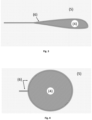
- This design comprises a support band 1 ( Figure 1 ) made by a semi-rigid material, such as a polymer or other (PVC, Nylon, Acrylic, Aluminium), this structural element shall be able to contour the small blade leading edge radius without breaking.
- the support band material, geometry and dimensions are defined to bend and develop a small curvature radius on the longitudinal direction that allows it to easily contour the blade air foil shape while in the transversal direction it will have a minor bending under the vacuum load.
- the flexible sealing element 2 ( Figure 2 , Figure 3 ) is an elastic material that has an extremely high deformability, like a foam or other advanced microscopically sealing elastic material that can again sustain very small radius of curvature without changing significantly the natural cross section shape (EPDM, Neoprene, Rubber, Silicone). It keeps the initial properties and shape after repetitive bend and it can fill and adapt to the rugosity of the surface in which it is being attached to, delivering a much tighter connection, without leaking.
- the system can have one or more vacuum cavities 3 ( Figure 1 ), each cavity is generated by adding one sealing element 2 ( Figure 1 ) between two existing flexible elements.
- the support band 1 can be produced from the same material or be an assembly of elements, built by more than one material, that deliver orthotropy properties. These properties are achieved by adding materials with different properties. For example, a flexible membrane band that allows bending around the longitudinal axis of the sealing system and discrete stiffening elements bonded with some regular spacing that restrict bending displacement around the transversal axis, avoiding loss of function or choke under vacuum forces.
- the same concept of assembly of elements can be used for the complete sealing system, it can result from an extruded foam that has built in stiffeners, in this case the longitudinal flexibility is given by the foam properties and the transversal stiffness is given by a wireframe that is embedded on the foam.
- This frame in particular, can be made by connecting a series of metallic tubes closely spaced in the transversal direction and connected on top and on bottom with two thin wires on the longitudinal direction.
- the sealing is built by one or more suction cavities that create the necessary force to fix the sealing to the blade, acting as a strong interface.
- This interface can sustain large structural loads in any direction, namely roof weight, rain impact forces, water or snow weight and aerodynamic loads that are applied on the roof or floor need to be sustained by the sealing.
- the sealing can sustain thousands of newtons on all directions.
- the interface also avoids any water ingression on the interior part of the chamber.
- the cavities' volume can be expanded making the support band larger in the transverse direction, and the number of cavities can be increased by adding another sealing element.
- the added sealing elements are not necessarily in the same material as the top and bottom end 2 ( Figure 1 ), this difference allows the management of the transversal deformed shape under vacuum 1 ( Figure 1 ) and the adaptation of the friction coefficient of the complete sealing.
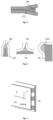
- a skin or membrane 5 , Figure 3 and Figure 4 is then attached to the sealing, creating a roof that will cover the operators on top and make the water slide from the sealing to the outer perimeter of the habitat at an angle.
- the skin or membrane is also attached to the sealing below the suspended platform to create the desired floor enclosure of the complete platform on top and on bottom.
- the vertical attachment position of the membrane 5 ( Figure 1 ) into the support band may vary, as long as it does not compromise the efficiency of the assembly, although the middle position is considered to be, structurally, the more effective.
- the sealing system length 6 is larger than the largest perimeter of the blade cross section to seal, this is the case to allow the sealing adaptation to the different blade shape perimeters.
- the present disclosure can include add-on stoppers made of flexible and impermeable materials (foam, EPDM, silicone, Latex, etc.) with different shapes that have, but are not limited to, the following main functions: manage very low curvature radius and solve small gaps not accommodated by the baseline sealing device; surpass obstacles such as vortex generators, turbulators and others.
- add-on stoppers can be used on the trailing edge gap 7 ( Figure 5 ) , they can be used to close gaps when the two sides of the sealing meet with an angle close to 90°, and to increase locally the radius of curvature to one that is more compatible to the sealing radius limits.
- the Figure 6 show an example of three possible stoppers, one for the mating of the sealing strap around the trailing edge 8 , the other for the mating of the sealing strap when it makes close to 90 degrees angles with the blade surface 9 , and one to increase the bending radius locally 10 .
- These are mere examples of the shapes that can be used but the solution is not limited to them, as other variations can be used to solve any localized limitation of the sealing system.
- the sealing when in contact with the blade immediately creates a delta pressure on the vacuum cavity, starting from the suction pipe connection area and then propagating along the sealing longitudinal length. This is achieved due to a balance between suction system flow rate, pipe diameter and shape and finally, sealing cross section area.
- This disclosure operates in a manner that in the beginning of the sealing installation by the operators the system produces higher flow rates with relatively low delta pressure, this is needed to accommodate some leaks that can happen here and there during the installation process.
- the suction system After having the sealing system fixed (small pressure differential along the full sealing) the suction system is commuted to a lower vacuum suction to increase the load carrying capability of the sealing.
- the delta pressure can be monitored along the full sealing to determine the suction level in different sealing areas and in this way control and monitor the system during the attachment process and operation.
- the ambient pressure and local pressure are also measured near the suction engines and near the connection of the suction pipe and the sealing device, to effectively control the desired pressure along the sealing device and piping.
- This method of using two different vacuum systems allows the system to be easy to operate and have high performance in fixing speed and load carrying capability of the sealing.
Landscapes
- Engineering & Computer Science (AREA)
- Life Sciences & Earth Sciences (AREA)
- Sustainable Development (AREA)
- Sustainable Energy (AREA)
- Chemical & Material Sciences (AREA)
- Combustion & Propulsion (AREA)
- Mechanical Engineering (AREA)
- General Engineering & Computer Science (AREA)
- Wind Motors (AREA)
- Tents Or Canopies (AREA)
Applications Claiming Priority (1)
| Application Number | Priority Date | Filing Date | Title |
|---|---|---|---|
| PT11739321 | 2021-08-11 |
Publications (3)
| Publication Number | Publication Date |
|---|---|
| EP4134544A1 true EP4134544A1 (de) | 2023-02-15 |
| EP4134544C0 EP4134544C0 (de) | 2024-09-18 |
| EP4134544B1 EP4134544B1 (de) | 2024-09-18 |
Family
ID=84840189
Family Applications (1)
| Application Number | Title | Priority Date | Filing Date |
|---|---|---|---|
| EP21191755.4A Active EP4134544B1 (de) | 2021-08-11 | 2021-08-17 | Dichtungsvorrichtung und verfahren zur durchführung der wartung von windflügeln einer windenergieanlage in einer geschlossenen umgebung |
Country Status (2)
| Country | Link |
|---|---|
| EP (1) | EP4134544B1 (de) |
| PL (1) | PL4134544T3 (de) |
Citations (7)
| Publication number | Priority date | Publication date | Assignee | Title |
|---|---|---|---|---|
| DE19909698A1 (de) | 1998-09-22 | 2000-04-13 | Siebert Antonius J | Vorrichtung zur Durchführung von Reparatur- und Serviceleistungen insbesondere an Rotorblättern von Windkraftanlagen |
| DE102010011365A1 (de) * | 2010-03-12 | 2011-09-15 | Andre Duchow | Wetterschutz für Arbeitsbühnen an Propellerblättern von Windkraftanlagen |
| US20150204193A1 (en) * | 2010-01-08 | 2015-07-23 | Sky Climber Wind Solutions Llc | Method of repairing a wind turbine blade |
| EP2957538A1 (de) | 2013-02-12 | 2015-12-23 | Global Energy Services Siemsa S.A. | Vorrichtung zum schutz von hebebühnen zur wartung von windgeneratoren |
| GB2550842A (en) | 2016-05-11 | 2017-12-06 | Rotos 360 Ltd | Apparatus and method for repairing fibre-composite structures |
| US20190257295A1 (en) * | 2016-06-17 | 2019-08-22 | WP Systems GmbH | Rotor blade inspection rig |
| WO2020058099A1 (en) | 2018-09-17 | 2020-03-26 | Pp Energy Aps | Water intrusion prevention system for turbine blades |
-
2021
- 2021-08-17 EP EP21191755.4A patent/EP4134544B1/de active Active
- 2021-08-17 PL PL21191755.4T patent/PL4134544T3/pl unknown
Patent Citations (7)
| Publication number | Priority date | Publication date | Assignee | Title |
|---|---|---|---|---|
| DE19909698A1 (de) | 1998-09-22 | 2000-04-13 | Siebert Antonius J | Vorrichtung zur Durchführung von Reparatur- und Serviceleistungen insbesondere an Rotorblättern von Windkraftanlagen |
| US20150204193A1 (en) * | 2010-01-08 | 2015-07-23 | Sky Climber Wind Solutions Llc | Method of repairing a wind turbine blade |
| DE102010011365A1 (de) * | 2010-03-12 | 2011-09-15 | Andre Duchow | Wetterschutz für Arbeitsbühnen an Propellerblättern von Windkraftanlagen |
| EP2957538A1 (de) | 2013-02-12 | 2015-12-23 | Global Energy Services Siemsa S.A. | Vorrichtung zum schutz von hebebühnen zur wartung von windgeneratoren |
| GB2550842A (en) | 2016-05-11 | 2017-12-06 | Rotos 360 Ltd | Apparatus and method for repairing fibre-composite structures |
| US20190257295A1 (en) * | 2016-06-17 | 2019-08-22 | WP Systems GmbH | Rotor blade inspection rig |
| WO2020058099A1 (en) | 2018-09-17 | 2020-03-26 | Pp Energy Aps | Water intrusion prevention system for turbine blades |
Also Published As
| Publication number | Publication date |
|---|---|
| PL4134544T3 (pl) | 2025-03-24 |
| EP4134544C0 (de) | 2024-09-18 |
| EP4134544B1 (de) | 2024-09-18 |
Similar Documents
| Publication | Publication Date | Title |
|---|---|---|
| CN103270297B (zh) | 风力发电装置的机舱罩连接部结构 | |
| EP3189232A1 (de) | Enteisungssystem für eine windturbinenschaufel | |
| EP3378139B1 (de) | Übergang für den durchgang durch eine wand und modul | |
| CA3216025A1 (en) | Electric junction box mount apparatus | |
| EP4134544B1 (de) | Dichtungsvorrichtung und verfahren zur durchführung der wartung von windflügeln einer windenergieanlage in einer geschlossenen umgebung | |
| DK201870729A1 (en) | A ROOF WINDOW WITH IMPROVED INSULATION AND SEALING PROPERTIES, AND A METHOD OF ASSEMBLING SUCH A ROOF WINDOW | |
| EP3186450A1 (de) | Tragbare flexible dichtungsvorrichtung für gitteröffnungen | |
| CN210133261U (zh) | 一种气密汽笛拉索装置及船舶 | |
| ES2991636T3 (es) | Dispositivo de sellado y método para realizar el mantenimiento de álabes de turbina eólica en un entorno cerrado | |
| US20090066037A1 (en) | sealing device configured to form an air seal around a pipe | |
| AU2019352502B2 (en) | Sealing apparatus | |
| FI128880B (en) | Water drainage system | |
| CN203685491U (zh) | 一种管缆防雨罩 | |
| CN207176741U (zh) | 移动式复合止水系统 | |
| KR20130082092A (ko) | 과압 완화 지붕 패널 | |
| JP6998856B2 (ja) | 止水構造 | |
| CN203640579U (zh) | 一种带风雨密装置的除雾器 | |
| CN113602418A (zh) | 一种水密舱盖及其使用方法 | |
| CN222557830U (zh) | 一种具有落雪引导装置的气膜设备 | |
| CN217537718U (zh) | 一种土建风道的对接结构 | |
| CN221074476U (zh) | 一种用于海底储能系统的半刚性排气设备 | |
| CN211472942U (zh) | 伸缩缝连接装置及保温墙 | |
| CA2504063A1 (en) | Device and a method for drainage of water from rock caves | |
| RU2657374C1 (ru) | Кессон для подводного ремонта трубопровода | |
| CN104032823B (zh) | 防冻型的检查井 |
Legal Events
| Date | Code | Title | Description |
|---|---|---|---|
| PUAI | Public reference made under article 153(3) epc to a published international application that has entered the european phase |
Free format text: ORIGINAL CODE: 0009012 |
|
| STAA | Information on the status of an ep patent application or granted ep patent |
Free format text: STATUS: THE APPLICATION HAS BEEN PUBLISHED |
|
| AK | Designated contracting states |
Kind code of ref document: A1 Designated state(s): AL AT BE BG CH CY CZ DE DK EE ES FI FR GB GR HR HU IE IS IT LI LT LU LV MC MK MT NL NO PL PT RO RS SE SI SK SM TR |
|
| STAA | Information on the status of an ep patent application or granted ep patent |
Free format text: STATUS: REQUEST FOR EXAMINATION WAS MADE |
|
| 17P | Request for examination filed |
Effective date: 20230320 |
|
| RBV | Designated contracting states (corrected) |
Designated state(s): AL AT BE BG CH CY CZ DE DK EE ES FI FR GB GR HR HU IE IS IT LI LT LU LV MC MK MT NL NO PL PT RO RS SE SI SK SM TR |
|
| GRAP | Despatch of communication of intention to grant a patent |
Free format text: ORIGINAL CODE: EPIDOSNIGR1 |
|
| STAA | Information on the status of an ep patent application or granted ep patent |
Free format text: STATUS: GRANT OF PATENT IS INTENDED |
|
| RIC1 | Information provided on ipc code assigned before grant |
Ipc: F03D 80/50 20160101AFI20240320BHEP |
|
| INTG | Intention to grant announced |
Effective date: 20240409 |
|
| RIN1 | Information on inventor provided before grant (corrected) |
Inventor name: CARDOSO CARNEIRO, PEDRO MIGUEL Inventor name: ALVES CARDOSO, CRISTOVAO Inventor name: SOARES LOUREIRO, JOAO PEDRO |
|
| GRAS | Grant fee paid |
Free format text: ORIGINAL CODE: EPIDOSNIGR3 |
|
| GRAA | (expected) grant |
Free format text: ORIGINAL CODE: 0009210 |
|
| STAA | Information on the status of an ep patent application or granted ep patent |
Free format text: STATUS: THE PATENT HAS BEEN GRANTED |
|
| AK | Designated contracting states |
Kind code of ref document: B1 Designated state(s): AL AT BE BG CH CY CZ DE DK EE ES FI FR GB GR HR HU IE IS IT LI LT LU LV MC MK MT NL NO PL PT RO RS SE SI SK SM TR |
|
| REG | Reference to a national code |
Ref country code: GB Ref legal event code: FG4D |
|
| REG | Reference to a national code |
Ref country code: CH Ref legal event code: EP |
|
| REG | Reference to a national code |
Ref country code: IE Ref legal event code: FG4D |
|
| REG | Reference to a national code |
Ref country code: DE Ref legal event code: R096 Ref document number: 602021018885 Country of ref document: DE |
|
| U01 | Request for unitary effect filed |
Effective date: 20241011 |
|
| REG | Reference to a national code |
Ref country code: ES Ref legal event code: FG2A Ref document number: 2991636 Country of ref document: ES Kind code of ref document: T3 Effective date: 20241204 |
|
| U07 | Unitary effect registered |
Designated state(s): AT BE BG DE DK EE FI FR IT LT LU LV MT NL PT RO SE SI Effective date: 20241030 |
|
| PG25 | Lapsed in a contracting state [announced via postgrant information from national office to epo] |
Ref country code: NO Free format text: LAPSE BECAUSE OF FAILURE TO SUBMIT A TRANSLATION OF THE DESCRIPTION OR TO PAY THE FEE WITHIN THE PRESCRIBED TIME-LIMIT Effective date: 20241218 |
|
| PG25 | Lapsed in a contracting state [announced via postgrant information from national office to epo] |
Ref country code: GR Free format text: LAPSE BECAUSE OF FAILURE TO SUBMIT A TRANSLATION OF THE DESCRIPTION OR TO PAY THE FEE WITHIN THE PRESCRIBED TIME-LIMIT Effective date: 20241219 |
|
| PG25 | Lapsed in a contracting state [announced via postgrant information from national office to epo] |
Ref country code: HR Free format text: LAPSE BECAUSE OF FAILURE TO SUBMIT A TRANSLATION OF THE DESCRIPTION OR TO PAY THE FEE WITHIN THE PRESCRIBED TIME-LIMIT Effective date: 20240918 |
|
| PG25 | Lapsed in a contracting state [announced via postgrant information from national office to epo] |
Ref country code: RS Free format text: LAPSE BECAUSE OF FAILURE TO SUBMIT A TRANSLATION OF THE DESCRIPTION OR TO PAY THE FEE WITHIN THE PRESCRIBED TIME-LIMIT Effective date: 20241218 |
|
| PG25 | Lapsed in a contracting state [announced via postgrant information from national office to epo] |
Ref country code: RS Free format text: LAPSE BECAUSE OF FAILURE TO SUBMIT A TRANSLATION OF THE DESCRIPTION OR TO PAY THE FEE WITHIN THE PRESCRIBED TIME-LIMIT Effective date: 20241218 Ref country code: NO Free format text: LAPSE BECAUSE OF FAILURE TO SUBMIT A TRANSLATION OF THE DESCRIPTION OR TO PAY THE FEE WITHIN THE PRESCRIBED TIME-LIMIT Effective date: 20241218 Ref country code: HR Free format text: LAPSE BECAUSE OF FAILURE TO SUBMIT A TRANSLATION OF THE DESCRIPTION OR TO PAY THE FEE WITHIN THE PRESCRIBED TIME-LIMIT Effective date: 20240918 Ref country code: GR Free format text: LAPSE BECAUSE OF FAILURE TO SUBMIT A TRANSLATION OF THE DESCRIPTION OR TO PAY THE FEE WITHIN THE PRESCRIBED TIME-LIMIT Effective date: 20241219 |
|
| PG25 | Lapsed in a contracting state [announced via postgrant information from national office to epo] |
Ref country code: IS Free format text: LAPSE BECAUSE OF FAILURE TO SUBMIT A TRANSLATION OF THE DESCRIPTION OR TO PAY THE FEE WITHIN THE PRESCRIBED TIME-LIMIT Effective date: 20250118 |
|
| PG25 | Lapsed in a contracting state [announced via postgrant information from national office to epo] |
Ref country code: SM Free format text: LAPSE BECAUSE OF FAILURE TO SUBMIT A TRANSLATION OF THE DESCRIPTION OR TO PAY THE FEE WITHIN THE PRESCRIBED TIME-LIMIT Effective date: 20240918 |
|
| PG25 | Lapsed in a contracting state [announced via postgrant information from national office to epo] |
Ref country code: CZ Free format text: LAPSE BECAUSE OF FAILURE TO SUBMIT A TRANSLATION OF THE DESCRIPTION OR TO PAY THE FEE WITHIN THE PRESCRIBED TIME-LIMIT Effective date: 20240918 |
|
| PG25 | Lapsed in a contracting state [announced via postgrant information from national office to epo] |
Ref country code: SK Free format text: LAPSE BECAUSE OF FAILURE TO SUBMIT A TRANSLATION OF THE DESCRIPTION OR TO PAY THE FEE WITHIN THE PRESCRIBED TIME-LIMIT Effective date: 20240918 |
|
| PLBE | No opposition filed within time limit |
Free format text: ORIGINAL CODE: 0009261 |
|
| STAA | Information on the status of an ep patent application or granted ep patent |
Free format text: STATUS: NO OPPOSITION FILED WITHIN TIME LIMIT |
|
| 26N | No opposition filed |
Effective date: 20250619 |
|
| U20 | Renewal fee for the european patent with unitary effect paid |
Year of fee payment: 5 Effective date: 20250808 |
|
| PGFP | Annual fee paid to national office [announced via postgrant information from national office to epo] |
Ref country code: ES Payment date: 20250909 Year of fee payment: 5 |
|
| PGFP | Annual fee paid to national office [announced via postgrant information from national office to epo] |
Ref country code: PL Payment date: 20250812 Year of fee payment: 5 |
|
| PGFP | Annual fee paid to national office [announced via postgrant information from national office to epo] |
Ref country code: GB Payment date: 20250826 Year of fee payment: 5 |
|
| PGFP | Annual fee paid to national office [announced via postgrant information from national office to epo] |
Ref country code: IE Payment date: 20250819 Year of fee payment: 5 |
|
| REG | Reference to a national code |
Ref country code: CH Ref legal event code: H13 Free format text: ST27 STATUS EVENT CODE: U-0-0-H10-H13 (AS PROVIDED BY THE NATIONAL OFFICE) Effective date: 20260324 |
|
| PG25 | Lapsed in a contracting state [announced via postgrant information from national office to epo] |
Ref country code: MC Free format text: LAPSE BECAUSE OF FAILURE TO SUBMIT A TRANSLATION OF THE DESCRIPTION OR TO PAY THE FEE WITHIN THE PRESCRIBED TIME-LIMIT Effective date: 20240918 |
|
| PG25 | Lapsed in a contracting state [announced via postgrant information from national office to epo] |
Ref country code: CH Free format text: LAPSE BECAUSE OF NON-PAYMENT OF DUE FEES Effective date: 20250831 |