EP4134545A1 - Pale d'éolienne, éolienne et procédé de maintien de pale d'éolienne - Google Patents
Pale d'éolienne, éolienne et procédé de maintien de pale d'éolienne Download PDFInfo
- Publication number
- EP4134545A1 EP4134545A1 EP21812228.1A EP21812228A EP4134545A1 EP 4134545 A1 EP4134545 A1 EP 4134545A1 EP 21812228 A EP21812228 A EP 21812228A EP 4134545 A1 EP4134545 A1 EP 4134545A1
- Authority
- EP
- European Patent Office
- Prior art keywords
- leading edge
- wind turbine
- blade
- protector
- edge protector
- Prior art date
- Legal status (The legal status is an assumption and is not a legal conclusion. Google has not performed a legal analysis and makes no representation as to the accuracy of the status listed.)
- Pending
Links
Images




Classifications
-
- F—MECHANICAL ENGINEERING; LIGHTING; HEATING; WEAPONS; BLASTING
- F03—MACHINES OR ENGINES FOR LIQUIDS; WIND, SPRING, OR WEIGHT MOTORS; PRODUCING MECHANICAL POWER OR A REACTIVE PROPULSIVE THRUST, NOT OTHERWISE PROVIDED FOR
- F03D—WIND MOTORS
- F03D1/00—Wind motors with rotation axis substantially parallel to the air flow entering the rotor
- F03D1/06—Rotors
- F03D1/065—Rotors characterised by their construction elements
- F03D1/0675—Rotors characterised by their construction elements of the blades
- F03D1/0688—Rotors characterised by their construction elements of the blades of the leading edge region, e.g. reinforcements
-
- F—MECHANICAL ENGINEERING; LIGHTING; HEATING; WEAPONS; BLASTING
- F03—MACHINES OR ENGINES FOR LIQUIDS; WIND, SPRING, OR WEIGHT MOTORS; PRODUCING MECHANICAL POWER OR A REACTIVE PROPULSIVE THRUST, NOT OTHERWISE PROVIDED FOR
- F03D—WIND MOTORS
- F03D1/00—Wind motors with rotation axis substantially parallel to the air flow entering the rotor
- F03D1/06—Rotors
- F03D1/0608—Rotors characterised by their aerodynamic shape
- F03D1/0633—Rotors characterised by their aerodynamic shape of the blades
- F03D1/0643—Rotors characterised by their aerodynamic shape of the blades of the leading edge region
-
- F—MECHANICAL ENGINEERING; LIGHTING; HEATING; WEAPONS; BLASTING
- F03—MACHINES OR ENGINES FOR LIQUIDS; WIND, SPRING, OR WEIGHT MOTORS; PRODUCING MECHANICAL POWER OR A REACTIVE PROPULSIVE THRUST, NOT OTHERWISE PROVIDED FOR
- F03D—WIND MOTORS
- F03D1/00—Wind motors with rotation axis substantially parallel to the air flow entering the rotor
- F03D1/06—Rotors
- F03D1/065—Rotors characterised by their construction elements
-
- F—MECHANICAL ENGINEERING; LIGHTING; HEATING; WEAPONS; BLASTING
- F03—MACHINES OR ENGINES FOR LIQUIDS; WIND, SPRING, OR WEIGHT MOTORS; PRODUCING MECHANICAL POWER OR A REACTIVE PROPULSIVE THRUST, NOT OTHERWISE PROVIDED FOR
- F03D—WIND MOTORS
- F03D1/00—Wind motors with rotation axis substantially parallel to the air flow entering the rotor
- F03D1/06—Rotors
- F03D1/065—Rotors characterised by their construction elements
- F03D1/0675—Rotors characterised by their construction elements of the blades
-
- F—MECHANICAL ENGINEERING; LIGHTING; HEATING; WEAPONS; BLASTING
- F03—MACHINES OR ENGINES FOR LIQUIDS; WIND, SPRING, OR WEIGHT MOTORS; PRODUCING MECHANICAL POWER OR A REACTIVE PROPULSIVE THRUST, NOT OTHERWISE PROVIDED FOR
- F03D—WIND MOTORS
- F03D80/00—Details, components or accessories not provided for in groups F03D1/00 - F03D17/00
- F03D80/50—Maintenance or repair
-
- F—MECHANICAL ENGINEERING; LIGHTING; HEATING; WEAPONS; BLASTING
- F03—MACHINES OR ENGINES FOR LIQUIDS; WIND, SPRING, OR WEIGHT MOTORS; PRODUCING MECHANICAL POWER OR A REACTIVE PROPULSIVE THRUST, NOT OTHERWISE PROVIDED FOR
- F03D—WIND MOTORS
- F03D80/00—Details, components or accessories not provided for in groups F03D1/00 - F03D17/00
- F03D80/50—Maintenance or repair
- F03D80/502—Maintenance or repair of rotors or blades
-
- F—MECHANICAL ENGINEERING; LIGHTING; HEATING; WEAPONS; BLASTING
- F05—INDEXING SCHEMES RELATING TO ENGINES OR PUMPS IN VARIOUS SUBCLASSES OF CLASSES F01-F04
- F05B—INDEXING SCHEME RELATING TO WIND, SPRING, WEIGHT, INERTIA OR LIKE MOTORS, TO MACHINES OR ENGINES FOR LIQUIDS COVERED BY SUBCLASSES F03B, F03D AND F03G
- F05B2230/00—Manufacture
- F05B2230/80—Repairing, retrofitting or upgrading methods
-
- F—MECHANICAL ENGINEERING; LIGHTING; HEATING; WEAPONS; BLASTING
- F05—INDEXING SCHEMES RELATING TO ENGINES OR PUMPS IN VARIOUS SUBCLASSES OF CLASSES F01-F04
- F05B—INDEXING SCHEME RELATING TO WIND, SPRING, WEIGHT, INERTIA OR LIKE MOTORS, TO MACHINES OR ENGINES FOR LIQUIDS COVERED BY SUBCLASSES F03B, F03D AND F03G
- F05B2230/00—Manufacture
- F05B2230/90—Coating; Surface treatment
-
- F—MECHANICAL ENGINEERING; LIGHTING; HEATING; WEAPONS; BLASTING
- F05—INDEXING SCHEMES RELATING TO ENGINES OR PUMPS IN VARIOUS SUBCLASSES OF CLASSES F01-F04
- F05B—INDEXING SCHEME RELATING TO WIND, SPRING, WEIGHT, INERTIA OR LIKE MOTORS, TO MACHINES OR ENGINES FOR LIQUIDS COVERED BY SUBCLASSES F03B, F03D AND F03G
- F05B2240/00—Components
- F05B2240/20—Rotors
- F05B2240/30—Characteristics of rotor blades, i.e. of any element transforming dynamic fluid energy to or from rotational energy and being attached to a rotor
- F05B2240/303—Details of the leading edge
-
- F—MECHANICAL ENGINEERING; LIGHTING; HEATING; WEAPONS; BLASTING
- F05—INDEXING SCHEMES RELATING TO ENGINES OR PUMPS IN VARIOUS SUBCLASSES OF CLASSES F01-F04
- F05B—INDEXING SCHEME RELATING TO WIND, SPRING, WEIGHT, INERTIA OR LIKE MOTORS, TO MACHINES OR ENGINES FOR LIQUIDS COVERED BY SUBCLASSES F03B, F03D AND F03G
- F05B2280/00—Materials; Properties thereof
- F05B2280/60—Properties or characteristics given to material by treatment or manufacturing
- F05B2280/6011—Coating
-
- Y—GENERAL TAGGING OF NEW TECHNOLOGICAL DEVELOPMENTS; GENERAL TAGGING OF CROSS-SECTIONAL TECHNOLOGIES SPANNING OVER SEVERAL SECTIONS OF THE IPC; TECHNICAL SUBJECTS COVERED BY FORMER USPC CROSS-REFERENCE ART COLLECTIONS [XRACs] AND DIGESTS
- Y02—TECHNOLOGIES OR APPLICATIONS FOR MITIGATION OR ADAPTATION AGAINST CLIMATE CHANGE
- Y02E—REDUCTION OF GREENHOUSE GAS [GHG] EMISSIONS, RELATED TO ENERGY GENERATION, TRANSMISSION OR DISTRIBUTION
- Y02E10/00—Energy generation through renewable energy sources
- Y02E10/70—Wind energy
- Y02E10/72—Wind turbines with rotation axis in wind direction
-
- Y—GENERAL TAGGING OF NEW TECHNOLOGICAL DEVELOPMENTS; GENERAL TAGGING OF CROSS-SECTIONAL TECHNOLOGIES SPANNING OVER SEVERAL SECTIONS OF THE IPC; TECHNICAL SUBJECTS COVERED BY FORMER USPC CROSS-REFERENCE ART COLLECTIONS [XRACs] AND DIGESTS
- Y02—TECHNOLOGIES OR APPLICATIONS FOR MITIGATION OR ADAPTATION AGAINST CLIMATE CHANGE
- Y02P—CLIMATE CHANGE MITIGATION TECHNOLOGIES IN THE PRODUCTION OR PROCESSING OF GOODS
- Y02P70/00—Climate change mitigation technologies in the production process for final industrial or consumer products
- Y02P70/50—Manufacturing or production processes characterised by the final manufactured product
Definitions
- This disclosure relates to a wind turbine blade, a wind turbine, and a repair method for a wind turbine blade.
- a leading edge protector may be attached to the leading edge portion of the wind turbine blade where erosion damage is likely to occur.
- Patent Document 1 discloses a technique for suppressing erosion damage by covering the leading edge portion of the wind turbine blade with a shield member on the blade tip side where the peripheral velocity of the wind turbine blade increases.
- Patent Document 1 WO2018/219524A
- a leading edge protector such as the shield member of Patent Document 1
- the leading edge protector is made of a material having a predetermined thickness, such as a plate material, to have excellent erosion resistance performance, it is necessary to bend the material into a shape corresponding to the leading edge portion. Since the leading edge portion has a curved shape that takes into account the aerodynamic performance of the wind turbine blade, if a hard material with excellent wear resistance is used, it is not easy to process.
- At least one embodiment of the present disclosure was made in view of the above problems, and an object thereof is to provide a wind turbine blade that can be easily manufactured while ensuring good erosion resistance performance, a wind turbine blade including the wind turbine blade, and a repair method for a wind turbine blade.
- a wind turbine blade includes: a blade body; and a leading edge protector covering a leading edge portion of the blade body.
- the leading edge protector includes: a body layer; and a coating layer having higher hardness than the body layer and at least partially covering a surface of the body layer.
- a wind turbine according to at least one embodiment of the present disclosure includes the wind turbine blade according to at least one embodiment of the present disclosure.
- a repair method for a wind turbine blade includes, for repairing a wind turbine blade including a blade body; and a leading edge protector covering a leading edge portion of the blade body, the leading edge protector including: a body layer; and a coating layer having higher hardness than the body layer and at least partially covering a surface of the body layer, a step of inserting a repair material having a longitudinal shape into a damaged portion generated in the leading edge protector; a step of deforming the repair material into a shape corresponding to the damaged portion by compressing the repair material from outside the damaged portion; and a step of removing excess of the repair material that is exposed from the damaged portion.
- At least one embodiment of the present disclosure provides a wind turbine blade that can be easily manufactured while ensuring good erosion resistance performance, a wind turbine blade including the wind turbine blade, and a repair method for a wind turbine blade.
- an expression of relative or absolute arrangement such as “in a direction”, “along a direction”, “parallel”, “orthogonal”, “centered”, “concentric” and “coaxial” shall not be construed as indicating only the arrangement in a strict literal sense, but also includes a state where the arrangement is relatively displaced by a tolerance, or by an angle or a distance whereby it is possible to achieve the same function.
- an expression of an equal state such as “same” “equal” and “uniform” shall not be construed as indicating only the state in which the feature is strictly equal, but also includes a state in which there is a tolerance or a difference that can still achieve the same function.
- an expression of a shape such as a rectangular shape or a cylindrical shape shall not be construed as only the geometrically strict shape, but also includes a shape with unevenness or chamfered corners within the range in which the same effect can be achieved.
- FIG. 1 is a schematic overall configuration diagram of the wind turbine 1 according to an embodiment.
- the wind turbine 1 includes at least one wind turbine blade 2.
- the wind turbine blade 2 is attached to a hub 4 to form a wind turbine rotor 6 that is rotatable around the rotation axis together with the hub 4.
- three wind turbine blades 2 are attached to the hub 4 around the rotation axis at equal intervals.
- Each wind turbine blade 2 has a blade root portion 12 connected to the hub 4 and a blade tip portion 14 opposite to the blade root portion 12 in the blade longitudinal direction.
- the wind turbine rotor 6 is rotatably attached to a nacelle 8 pivotably provided on a tower 10. In the wind turbine 1 having such a configuration, when the wind hits the wind turbine blades 2, the wind turbine rotor 6 including the wind turbine blades 2 and the hub 4 rotates around the rotation axis.
- the wind turbine 1 may be configured as a wind power generating apparatus.
- the nacelle 8 accommodates a generator and a power transmission mechanism for transmitting the rotation of the wind turbine rotor 6 to the generator.
- the rotation energy transmitted from the wind turbine rotor 6 to the generator through the power transmission mechanism is converted into electric energy by the generator.
- FIG. 2 is a schematic diagram showing the blade tip portion 14 side of the wind turbine blade 2 according to an embodiment.
- FIG. 3 is a cross-sectional view taken along line A-A in FIG. 2 according to an embodiment.
- the wind turbine blade 2 has a blade body 18.
- the blade body 18 extends from the blade root portion 12 (see FIG. 1 ) to the blade tip portion 14 along the blade longitudinal direction, and includes a leading edge portion 20 disposed on the front side in the blade chord direction and a trailing edge portion 22 disposed on the rear side in the blade chord direction.
- the blade body 18 has a skin including fiber-reinforced plastic.
- the fiber-reinforced plastic that makes up the skin may be, for example, glass fiber reinforced plastic (GFRP) or carbon fiber reinforced plastic (CFRP).
- the blade body 18 includes a suction-side skin 24 and a pressure-side skin 26 opposite to each other.
- the suction-side skin 24 and the pressure-side skin 26 are connected to each other in the leading edge portion 20 and the trailing edge portion 22 of the blade body 18 to form a hollow space 16 surrounded by the skin inside the blade body 18.
- the suction-side skin 24 and the pressure-side skin 26 are secured together, for example, by being glued with an adhesive or the like.
- the down-conductor 15 includes a conductive material and constitutes at least part of a path for the lightning current generated in the wind turbine blade 2 due to lightning strike to the wind turbine 1.
- the down-conductor 15 extends inside the hollow space 16 along the blade longitudinal direction from a tip receptor 17 provided in the blade tip portion 14 and is electrically connected to a ground wire (not shown) provided at a side of the blade root portion 12.
- the wind turbine blade 2 includes a leading edge protector 30.
- the leading edge protector 30 covers the leading edge portion 20 to protect the leading edge portion 20 from raindrops, dust, etc., during operation of the wind turbine 1, thus protecting the blade body 18 from erosion damage.
- the leading edge protector 30 includes a body layer 30a and a coating layer 30b.
- the body layer 30a is the main component of the leading edge protector 30 and has a curved shape corresponding to the leading edge portion 20.
- the coating layer 30b is disposed on the upper layer side of the body layer 30a so as to at least partially cover the surface of the body layer 30a, and has higher hardness than the body layer 30a.
- the body layer 30a includes a soft material (with lower hardness than the coating layer 30b).
- a soft material is formable due to low hardness and can be easily bent in conformity with the leading edge portion 20.
- the coating layer 30b is formed on the body layer 30a as a layer having higher hardness than the body layer 30a by thermal spraying, PVD, electroplating, or the like using a hard metal material such as TiN, DLC, or NiP.
- a hard metal material such as TiN, DLC, or NiP.
- the material that makes up the body layer 30a may have conductivity.
- a soft and highly conductive metal material such as an aluminum alloy may be used. If the body layer 30a is composed of a conductive member, for example, by electrically connecting the body layer 30a to the down-conductor 15, the leading edge protector 30 serves as at least part of the path for the lightning current generated in the wind turbine blade 2 due to lightning strike to the wind turbine 1, so it is possible to effectively improve the lightning resistance performance of the wind turbine blade 2.
- the coating layer 30b is formed on an outer surface 30a1 of the body layer 30a facing the outside. Thereby, during operation of the wind turbine blade 2, the coating layer 30b receives raindrops, sand dust, etc., flying from the outside, and thus the coating layer 30b protects the soft body layer 30a, resulting in good erosion performance.
- At least one of the outer surface 30a of the body layer 30a or the surface of the blade body 18, which touches the coating layer 30b, may be surface-treated to improve the adhesion of the coating layer 30b.
- the outer surface 30a of the body layer 30a may be anodized to improve the adhesion of the coating layer 30b.
- FIG. 4 is an enlarged perspective view showing the surface state of an aluminum alloy that has been anodized.
- An alumite layer M2 formed by anodizing is formed on the surface of the aluminum alloy M1.
- the alumite layer M2 has a structure in which many fine bores B are formed in a bulk body.
- the diameter of each bore B is, for example, several tens of nm, and billions to hundreds of millions of bores B are included per cm 3 .
- an inner surface 30a2 of the body layer 30a facing the leading edge portion 20 may also be anodized in the same manner as the outer surface 30a1.
- anodizing the outer surface 30a1, which touches the skin of the blade body 18, to improve the adhesion between the skin and the body layer 30a it is possible to effectively prevent the leading edge protector 30 from separating from the skin.
- FIG. 5 is a cross-sectional view taken along line A-A in FIG. 2 according to another embodiment.
- the coating layer 30b is formed on the inner surface 30a2 of the body layer 30a facing the leading edge portion 20. That is, in this embodiment, the coating layer 30b is interposed between the body layer 30a and the skin (suction-side skin 24 and pressure-side skin 26) of the blade body 18 in the leading edge portion 20 of the blade body 18.
- the coating layer 30b may be made of a material that can improve the adhesion of the leading edge protector 30 to the blade body 18.
- the body layer 30a can be well secured to the skin of the blade body 18 via the coating layer 30b, and the wind turbine blade 2 with high reliability can be obtained with little risk of separating or falling off of the leading edge protector 30.
- the leading edge protector 30 having such configuration may be provided over a predetermined region of the leading edge portion 20 of the blade body 18 on the blade tip portion 14 side.
- the blade tip portion 14 side of the leading edge portion 20 is more prone to erosion damage due to the increased peripheral velocity, and it is more likely to be struck by lightning due to the elevated location. Therefore, by providing the leading edge protector 30 over this region, it is possible to effectively suppress erosion damage and improve the lightning resistance performance.
- FIG. 6 is a schematic diagram showing the blade tip portion 14 side of the wind turbine blade 2 according to another embodiment.
- FIGs. 7A to 7C are cross-sectional views taken along line C-C in FIG. 6 according to some embodiments.
- the leading edge protector 30 provided at the leading edge portion 20 includes a plurality of protector members 32a to 32i arranged along the blade longitudinal direction of the blade body 18, as shown in FIG. 6 .
- the leading edge protector 30 is composed of the plurality of protector members 32a to 32i, even in a wind turbine blade 2 that is large along the blade longitudinal direction of the blade body 18, it is possible to protect the leading edge portion 20 from erosion damage over a wide range.
- the plurality of protector members 32a to 32i may be arranged such that a pair of end portions 34, 36 of two adjacent protector members overlap each other. Thereby, it is possible to absorb strain that may occur in the leading edge protector 30 due to deformation or thermal expansion of the wind turbine blade 2 during operation of the wind turbine 1, and to prevent erosion damage caused by a gap between two adjacent protector members.
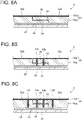
- the pair of end portions 34, 36 may have mutually complementary shapes, as shown in FIGs. 7A to 7C .
- the end portion 34 of the protector member 32d has a cross-sectional shape in which the upper layer side is partially cut off so as to partially reduce the thickness
- the end portion 36 of the protector member 32e has a cross-sectional shape in which the lower layer side is partially cut off so as to partially reduce the thickness, whereby they have mutually complementary shapes.
- the end portion 36 of the protector member 32e covers the upper layer side of the end portion 34 of the protector member 32d.
- FIG. 7A the end portion 34 of the protector member 32d has a cross-sectional shape in which the upper layer side is partially cut off so as to partially reduce the thickness
- the end portion 36 of the protector member 32e covers the upper layer side of the end portion 34 of the protector member 32d.
- the end portion 34 of the protector member 32d is flat on the lower layer side and is tapered toward the distal end
- the end portion 36 of the protector member 32e is flat on the upper layer side and is tapered toward the distal end, whereby they have mutually complementary shapes.
- the shapes of the pair of end portions 34, 36 shown in FIGs. 7A to 7C are merely illustrative, and the end portions may have other shapes.
- Each protector member may be secured to the skin of the blade body 18 via an adhesive layer 29.
- the adhesive layer 29 may be inserted between the pair of end portions 34, 36 as shown in FIG. 7B , or may not be inserted between the pair of end portions 34, 36 as shown in FIGs. 7A and 7C .
- FIGs. 8A to 8C are each an enlarged cross-sectional view showing a variation of the region D in FIG. 7A .
- the pair of end portions 34, 36 may be arranged with a highly elastic layer 38 having higher elastic modulus than the body layer 30a being interposed therebetween.
- the highly elastic layer 38 may be made of, for example, polyurethane resin, polyester resin, fluororesin, acrylic adhesive, or epoxy adhesive. Thereby, the highly elastic layer 38 absorbs thermal expansion or deformation that may occur in the wind turbine blade 2 during operation of the wind turbine 1 to effectively reduce strain of the wind turbine blade 2.
- the pair of end portions 34, 36 may be secured to each other by first bolt members 40a, 40b penetrating the pair of end portions 34, 36.
- the first bolt members 40a, 40b extend across the pair of end portions 34, 36 in the thickness direction of the skin to connect the protector members 32d, 32e having the pair of end portions 34, 36 to each other. This improves the adhesion strength between the pair of end portions 34, 36, and allows the leading edge protector 30 to have higher reliability.
- first bolt members 40a, 40b are made of a conductive material
- the contact resistance between each protector member can be reduced by the first bolt members 40a, 40b, so it is possible to improve the lightning resistance performance, for example, by reducing Joule heat caused by the lightning current generated in the leading edge protector 30 when the wind turbine blade 2 is struck by lightning.
- FIG. 8B shows two first bolt members, but the number of first bolt members may be any number.
- two adjacent protector members 32d, 32e may be connected via a connection plate 42 disposed between the leading edge protector 30 and the skin (suction-side skin 24 or pressure-side skin 26) of the blade body 18.
- the first bolt members 40a, 40b may secure the connection plate 42 together with the pair of end portions 34, 36. This allows the leading edge protector 30 composed of the plurality of protector members 32a to 32i to have high strength, providing the leading edge protector 30 with high reliability.
- connection plate 42 is made of a conductive material, the contact resistance between the plurality of protector members can be reduced by the connection plate 42, so it is possible to improve the lightning resistance performance, for example, by reducing Joule heat caused by the lightning current generated in the leading edge protector 30 when the wind turbine blade 2 is struck by lightning.
- FIG. 9 is a cross-sectional view taken along line A-A in FIG. 2 according to another embodiment.
- the leading edge protector 30 includes a first leading edge protector 30A and a second leading edge protector 30B.
- the first leading edge protector 30A extends from a suction-side secured portion 47a disposed on the suction-side skin 24 of the blade body 18 toward the leading edge side and has a flat plate shape inclined with respect to the blade chord direction of the blade body 18.
- the second leading edge protector 30B extends from a pressure-side secured portion 47b disposed on the pressure-side skin 26 of the blade body 18 toward the leading edge side and has a flat plate shape inclined with respect to the blade chord direction of the blade body 18.
- the first leading edge protector 30A and the second leading edge protector 30B are connected to each other at the leading edge side of the blade body 18.
- the leading edge portion 20 of the blade body 18 receives raindrops, dust, etc., from the front side obliquely.
- the impact caused by raindrops, dust, etc. is reduced, and erosion damage is reduced.
- first leading edge protector 30A and the second leading edge protector 30B are connected to each other via a joint portion 30c having higher hardness than the body layer 30a.
- the joint portion 30c is formed, for example, by joining the first leading edge protector 30A and the second leading edge protector 30B having flat plate shapes by build-up welding with their edges in abutment.
- a welding material with high hardness such as high chromium cast iron is preferably used for the joint portion 30c.
- FIG. 10 is a cross-sectional view taken along line A-A in FIG. 2 according to another embodiment.
- the leading edge protector 30 includes a first magnet 48a built into the body layer 30a and a second magnet 48b built into the skin (suction- side skin 24 and pressure-side skin 26) of the blade body 18.
- the first magnet 48a and the second magnet 48b are placed to face each other when the leading edge protector 30 is attached to the leading edge portion 20 of the blade body 18, and the leading edge protector 30 is attached to the blade body 18 by the magnetic attraction generated between the first magnet 48a and the second magnet 48b.
- the leading edge protector 30 can be well secured to the blade body 18 by the magnetic attraction generated between the first magnet 48a and the second magnet 48b, and the leading edge protector 30 can be effectively prevented from separating from the blade body 18.
- the first magnet 48a and the second magnet 48b may be permanent magnets or electromagnets.
- permanent magnets When permanent magnets are used as the first magnet 48a and the second magnet 48b, magnets with strong magnetic attraction, such as neodymium magnets, may be used.
- FIG. 11 is a perspective view of the leading edge protector 30 provided at the leading edge portion 20 of the blade body 18 according to an embodiment.
- FIG. 12 is a cross-sectional view taken along line E-E in FIG. 11 .
- the leading edge protector 30 according to each embodiment described above may be secured to the blade body 18 by a fastener structure 44.
- the fastener structure 44 includes a bolt hole 43 formed from the skin (suction- side skin 24 and pressure-side skin 26) of the blade body 18 to the leading edge protector 30, and a second bolt member 44a capable of engaging with the bolt hole 43.
- the second bolt member 44a has a head portion 44a1 with large diameter at one end, and a bolt body portion 44a2 passing through the bolt hole 43 at the other end is secured with a nut 44b.
- the fastener structure 44 By securing the leading edge protector 30 to the blade body 18 by such a fastener structure 44, for example, even when the fixing force of the adhesive layer 29 that bonds the leading edge protector 30 to the blade body 18 is reduced, the fastener structure 44 can maintain the fixation to the blade body 18, so that the wind turbine blade 2 with higher reliability can be achieved.
- the fastener structure 44 has a gap 45 between a side surface of the second bolt member 44a and an inner surface of the bolt hole 43.
- the gap 45 is formed in a substantially cylindrical shape so as to surround the second bolt member 44a between the head portion 44a1 and the nut 44b.
- FIG. 13 is a schematic diagram showing the blade tip portion14 side of the wind turbine blade 2 according to another embodiment.
- the plurality of protector members 32a to 32i are configured such that a boundary line 33 between two adjacent protector members intersects the blade chord direction of the blade body 18.
- the boundary line 33 is inclined with respect to the blade chord direction.
- the leading edge protector 30 is subjected to stress in a direction of separating from the skin of the blade body 18. Such stress tends to increase in the vicinity of the boundaries of the protector members 32a to 32i which constitute the leading edge protector 30. Therefore, when the boundary line 33 between two adjacent protector members intersects the blade chord direction, the stress is effectively reduced, so it is possible to effectively prevent the leading edge protector 30 from separating from the blade body 18.
- FIG. 14 is a flowchart showing steps of a repair method for the wind turbine blade 2 according to an embodiment.
- FIGs. 15A to 15C are explanatory diagrams corresponding to each step of FIG. 14 .
- the initial state of the wind turbine blade 2 to be repaired is assumed to be the situation as shown in FIG. 15A , where a damaged portion 50 exists in a portion of the leading edge protector 30 on the skin of the leading edge portion 20 of the blade body 18.
- a portion of the leading edge protector 30 is missing is shown here as the damaged portion 50, the form of the damaged portion 50 is not limited to this case.
- a repair member 52 is inserted into the damaged portion 50 in the leading edge protector 30 (step S1).
- the repair member 52 includes the same or substitutable similar material as the constituent material of the leading edge protector 30.
- the repair member 52 including the same or substitutable similar material as the constituent material of the body layer 30a, which is the main component of the leading edge protector 30, is used.
- the repair member 52 has a longitudinal shape that can be inserted into the damaged portion 50.
- the repair member 52 inserted into the damaged portion 50 is compressed from the outside to be deformed into a shape corresponding to the damaged portion 50 (step S2).
- Such compression can be performed, for example, by using a tool such as a hammer on a portion of the repair member 52 inserted in the damaged portion 50 that is exposed from the damaged portion 50.
- the compressed repair member 52 is deformed in conformity with the shape of the damaged portion 50 and fills a gap generated as the damaged portion 50 in the leading edge protector 30.
- step S3 the excess repair member 52 exposed from the damaged portion 50 is removed.
- step S2 as shown in FIG. 15B , a portion of the repair member 52 is exposed from the damaged portion 50 and thus is excess.
- Such exposed excess repair member 52 is removed in step S3 so that the surface of the leading edge protector 30 is flattened after repair, as shown in FIG. 15C .
- the damaged portion 50 when a damaged portion 50 occurs in the leading edge protector 30 provided at the leading edge portion 20 of the blade body 18, by compressing and deforming the repair member 52 inserted into the damaged portion 50 and then removing the excess portion, the damaged portion 50 can be easily repaired by efficient work.
- the damaged portion when a damaged portion occurs in the leading edge protector provided at the leading edge portion of the blade body, by compressing and deforming the repair material inserted into the damaged portion and then removing the excess portion, the damaged portion can be easily repaired by efficient work.
Landscapes
- Engineering & Computer Science (AREA)
- Life Sciences & Earth Sciences (AREA)
- Sustainable Development (AREA)
- Sustainable Energy (AREA)
- Chemical & Material Sciences (AREA)
- Combustion & Propulsion (AREA)
- Mechanical Engineering (AREA)
- General Engineering & Computer Science (AREA)
- Physics & Mathematics (AREA)
- Fluid Mechanics (AREA)
- Wind Motors (AREA)
Applications Claiming Priority (2)
| Application Number | Priority Date | Filing Date | Title |
|---|---|---|---|
| JP2020090321A JP7519811B2 (ja) | 2020-05-25 | 2020-05-25 | 風車翼、風車、及び、風車翼の補修方法 |
| PCT/JP2021/019121 WO2021241385A1 (fr) | 2020-05-25 | 2021-05-20 | Pale d'éolienne, éolienne et procédé de maintien de pale d'éolienne |
Publications (2)
| Publication Number | Publication Date |
|---|---|
| EP4134545A1 true EP4134545A1 (fr) | 2023-02-15 |
| EP4134545A4 EP4134545A4 (fr) | 2023-10-04 |
Family
ID=78744622
Family Applications (1)
| Application Number | Title | Priority Date | Filing Date |
|---|---|---|---|
| EP21812228.1A Pending EP4134545A4 (fr) | 2020-05-25 | 2021-05-20 | Pale d'éolienne, éolienne et procédé de maintien de pale d'éolienne |
Country Status (6)
| Country | Link |
|---|---|
| US (1) | US20230184226A1 (fr) |
| EP (1) | EP4134545A4 (fr) |
| JP (1) | JP7519811B2 (fr) |
| CN (1) | CN115552117A (fr) |
| TW (1) | TWI774387B (fr) |
| WO (1) | WO2021241385A1 (fr) |
Cited By (2)
| Publication number | Priority date | Publication date | Assignee | Title |
|---|---|---|---|---|
| EP4158185A1 (fr) * | 2020-06-02 | 2023-04-05 | Lm Wind Power R&D (Holland) B.V. | Pale d'éolienne dotée d'un système de protection contre la foudre |
| EP3919736B1 (fr) * | 2020-06-01 | 2024-08-14 | Mitsubishi Heavy Industries, Ltd. | Pale de turbine éolienne et éolienne |
Families Citing this family (2)
| Publication number | Priority date | Publication date | Assignee | Title |
|---|---|---|---|---|
| KR102895786B1 (ko) * | 2024-01-16 | 2025-12-04 | 재단법인한국조선해양기자재연구원 | 블레이드 보호 필름 |
| WO2026012560A1 (fr) * | 2024-07-12 | 2026-01-15 | Vestas Wind Systems A/S | Système de protection contre la foudre |
Family Cites Families (23)
| Publication number | Priority date | Publication date | Assignee | Title |
|---|---|---|---|---|
| CN1867770A (zh) * | 2003-02-28 | 2006-11-22 | 维斯塔斯风力系统有限公司 | 制造风轮机叶片的方法、风轮机叶片、前盖以及前盖的应用 |
| US11523488B1 (en) * | 2006-03-28 | 2022-12-06 | Amazon Technologies, Inc. | Wirelessly controllable communication module |
| WO2010129077A1 (fr) * | 2009-05-07 | 2010-11-11 | Vanderhye Robert A | Elimination de gaz à effet de serre de l'atmosphère |
| US20110142678A1 (en) * | 2010-11-23 | 2011-06-16 | General Electric Company | Erosion protection coating for rotor blade of wind turbine |
| US20130045105A1 (en) * | 2011-08-17 | 2013-02-21 | Howard Daniel Driver | Wind turbine blade and method of protecting the same |
| CN202468173U (zh) * | 2011-12-15 | 2012-10-03 | 保定华翼风电叶片研究开发有限公司 | 一种抗风沙腐蚀的风力发电叶片 |
| JP2013155723A (ja) * | 2012-01-31 | 2013-08-15 | Mitsubishi Heavy Ind Ltd | 風車回転翼及びこれを備えた風力発電装置 |
| WO2014033832A1 (fr) * | 2012-08-28 | 2014-03-06 | 株式会社日立製作所 | Procédé permettant de protéger une aube destinée à la production d'énergie éolienne et aube |
| EP2868920A4 (fr) * | 2012-12-27 | 2015-08-05 | Mitsubishi Heavy Ind Ltd | Pale de rotor de turbine éolienne et générateur à turbine éolienne la comprenant |
| CN103273255A (zh) * | 2013-05-29 | 2013-09-04 | 新兴铸管股份有限公司 | 高炉双钟炉顶大钟拉杆表面破损修复方法 |
| JP6397637B2 (ja) * | 2014-03-04 | 2018-09-26 | イビデン株式会社 | 複層コートアルミニウム基材 |
| GB201508827D0 (en) * | 2015-05-22 | 2015-07-01 | Sanderson Simon | Aerodynamic shroud and method |
| JP6421078B2 (ja) * | 2015-05-28 | 2018-11-07 | エムエイチアイ ヴェスタス オフショア ウィンド エー/エス | 風車翼及び風力発電装置、並びに風車翼の製造又は改造方法 |
| DE102015115190A1 (de) * | 2015-09-09 | 2017-03-09 | Fichtner & Schicht GmbH | Windenergieanlage |
| JP2017078187A (ja) * | 2015-10-19 | 2017-04-27 | 株式会社東芝 | 回転機器の腐食防止方法および回転機器 |
| DK3601784T3 (en) * | 2017-05-30 | 2025-11-10 | Siemens Gamesa Renewable Energy As | Insulation of a heating mat of a wind turbine blade |
| ES2957264T3 (es) | 2017-05-31 | 2024-01-16 | Siemens Gamesa Renewable Energy As | Escudo protector con marca de posicionamiento |
| EP3495124A1 (fr) * | 2017-12-06 | 2019-06-12 | 3M Innovative Properties Company | Solution de réparation et procédé de bande de protection de bord d'attaque d'éolienne |
| CN109268203A (zh) * | 2018-09-26 | 2019-01-25 | 江苏金风科技有限公司 | 用于风力发电机组的叶片、制造其的方法及风力发电机组 |
| JP6730407B2 (ja) * | 2018-11-16 | 2020-07-29 | 三菱重工業株式会社 | 風車翼およびその製造方法 |
| EP3879091B1 (fr) * | 2020-03-13 | 2024-03-27 | Siemens Gamesa Renewable Energy A/S | Ensemble pale d'éolienne et procédé de fabrication d'un ensemble pale d'éolienne |
| EP4071350A1 (fr) * | 2021-04-09 | 2022-10-12 | LM Wind Power A/S | Pale d'éolienne comportant un carénage |
| CN116658355B (zh) * | 2023-04-06 | 2026-04-03 | 株洲时代新材料科技股份有限公司 | 一种风力涡轮机叶片的前缘防护罩的高可靠性安装方法 |
-
2020
- 2020-05-25 JP JP2020090321A patent/JP7519811B2/ja active Active
-
2021
- 2021-05-20 CN CN202180034298.6A patent/CN115552117A/zh active Pending
- 2021-05-20 US US17/925,480 patent/US20230184226A1/en not_active Abandoned
- 2021-05-20 WO PCT/JP2021/019121 patent/WO2021241385A1/fr not_active Ceased
- 2021-05-20 EP EP21812228.1A patent/EP4134545A4/fr active Pending
- 2021-05-21 TW TW110118440A patent/TWI774387B/zh active
Cited By (3)
| Publication number | Priority date | Publication date | Assignee | Title |
|---|---|---|---|---|
| EP3919736B1 (fr) * | 2020-06-01 | 2024-08-14 | Mitsubishi Heavy Industries, Ltd. | Pale de turbine éolienne et éolienne |
| EP4158185A1 (fr) * | 2020-06-02 | 2023-04-05 | Lm Wind Power R&D (Holland) B.V. | Pale d'éolienne dotée d'un système de protection contre la foudre |
| EP4158185B1 (fr) * | 2020-06-02 | 2026-04-22 | Lm Wind Power R&D (Holland) B.V. | Pale d'éolienne dotée d'un système de protection contre la foudre |
Also Published As
| Publication number | Publication date |
|---|---|
| TWI774387B (zh) | 2022-08-11 |
| US20230184226A1 (en) | 2023-06-15 |
| TW202200897A (zh) | 2022-01-01 |
| EP4134545A4 (fr) | 2023-10-04 |
| CN115552117A (zh) | 2022-12-30 |
| WO2021241385A1 (fr) | 2021-12-02 |
| JP2021185309A (ja) | 2021-12-09 |
| JP7519811B2 (ja) | 2024-07-22 |
Similar Documents
| Publication | Publication Date | Title |
|---|---|---|
| US20230184226A1 (en) | Wind turbine blade, wind turbine, and repair method for wind turbine blade | |
| CN101871436B (zh) | 用于组合式叶片的闪电保护系统 | |
| JP4580169B2 (ja) | 風車用分割型ブレード及び風車の耐雷装置 | |
| EP2636897B1 (fr) | Pale de turbine éolienne | |
| US20080193292A1 (en) | Rotor blade with a lightning protection unit, wind energy system having the same and a method for constructing a rotor blade | |
| JP4192744B2 (ja) | 風力発電設備 | |
| EP3098438A1 (fr) | Pale de turbine éolienne et appareil de génération d'énergie éolienne, procédé de fabrication ou de rattrapage d'une pale d'éolienne | |
| EP3054151A1 (fr) | Appareil de production d'énergie éolienne | |
| US20130164141A1 (en) | Blade with semi-rigid trailing edge | |
| JPWO2017033249A1 (ja) | 風力発電装置 | |
| US11519390B2 (en) | Wind turbine blade including leading edge protector and wind turbine including the wind turbine blade | |
| US9458822B2 (en) | Rotor for a wind turbine | |
| WO2013084634A1 (fr) | Éolienne et dispositif de production d'énergie éolienne | |
| US20130272892A1 (en) | Noise reducer for rotor blade in wind turbine | |
| US20210363963A1 (en) | Windmill blade, windmill, and method of manufacturing windmill blade | |
| EP3248867A1 (fr) | Gaine de pales d'hélice | |
| US11795920B2 (en) | Lightning protection for a wind turbine blade | |
| JP2017207001A (ja) | 風車用ブレード、風車、風車用ブレードの製造方法および風車用ブレード接合構造 | |
| US11867155B2 (en) | Method for providing a wind turbine blade with lightning protection and a wind turbine blade | |
| CN111237124A (zh) | 一种集合风电叶片前缘防护和雷击防护的系统 | |
| CA2893720A1 (fr) | Raccord de reduction de pied pour pied de pale d'une pale de rotor d'eolienne, un pied de pale, une pale de rotor d'eolienne et une eolienne | |
| CN111692050A (zh) | 连接组件及包含其的风机叶片 | |
| US20240068438A1 (en) | Protective cap for a leading edge of a wind turbine blade | |
| WO2016057120A1 (fr) | Entretoise pour pale de rotor de turbine éolienne | |
| EP4019772B1 (fr) | Système de protection contre la foudre pour une éolienne |
Legal Events
| Date | Code | Title | Description |
|---|---|---|---|
| STAA | Information on the status of an ep patent application or granted ep patent |
Free format text: STATUS: THE INTERNATIONAL PUBLICATION HAS BEEN MADE |
|
| PUAI | Public reference made under article 153(3) epc to a published international application that has entered the european phase |
Free format text: ORIGINAL CODE: 0009012 |
|
| STAA | Information on the status of an ep patent application or granted ep patent |
Free format text: STATUS: REQUEST FOR EXAMINATION WAS MADE |
|
| 17P | Request for examination filed |
Effective date: 20221108 |
|
| AK | Designated contracting states |
Kind code of ref document: A1 Designated state(s): AL AT BE BG CH CY CZ DE DK EE ES FI FR GB GR HR HU IE IS IT LI LT LU LV MC MK MT NL NO PL PT RO RS SE SI SK SM TR |
|
| DAV | Request for validation of the european patent (deleted) | ||
| DAX | Request for extension of the european patent (deleted) | ||
| A4 | Supplementary search report drawn up and despatched |
Effective date: 20230831 |
|
| RIC1 | Information provided on ipc code assigned before grant |
Ipc: F03D 1/06 20060101ALI20230825BHEP Ipc: F03D 80/50 20160101AFI20230825BHEP |
|
| STAA | Information on the status of an ep patent application or granted ep patent |
Free format text: STATUS: EXAMINATION IS IN PROGRESS |
|
| 17Q | First examination report despatched |
Effective date: 20250513 |