EP4134552B1 - Kochsystem - Google Patents
Kochsystem Download PDFInfo
- Publication number
- EP4134552B1 EP4134552B1 EP22193813.7A EP22193813A EP4134552B1 EP 4134552 B1 EP4134552 B1 EP 4134552B1 EP 22193813 A EP22193813 A EP 22193813A EP 4134552 B1 EP4134552 B1 EP 4134552B1
- Authority
- EP
- European Patent Office
- Prior art keywords
- unit
- fan wheel
- fan
- cooking system
- impeller
- Prior art date
- Legal status (The legal status is an assumption and is not a legal conclusion. Google has not performed a legal analysis and makes no representation as to the accuracy of the status listed.)
- Active
Links
Images


Classifications
-
- F—MECHANICAL ENGINEERING; LIGHTING; HEATING; WEAPONS; BLASTING
- F04—POSITIVE - DISPLACEMENT MACHINES FOR LIQUIDS; PUMPS FOR LIQUIDS OR ELASTIC FLUIDS
- F04D—NON-POSITIVE-DISPLACEMENT PUMPS
- F04D29/00—Details, component parts, or accessories
- F04D29/26—Rotors specially for elastic fluids
- F04D29/28—Rotors specially for elastic fluids for centrifugal or helico-centrifugal pumps for radial-flow or helico-centrifugal pumps
- F04D29/281—Rotors specially for elastic fluids for centrifugal or helico-centrifugal pumps for radial-flow or helico-centrifugal pumps for fans or blowers
- F04D29/282—Rotors specially for elastic fluids for centrifugal or helico-centrifugal pumps for radial-flow or helico-centrifugal pumps for fans or blowers the leading edge of each vane being substantially parallel to the rotation axis
-
- H—ELECTRICITY
- H05—ELECTRIC TECHNIQUES NOT OTHERWISE PROVIDED FOR
- H05B—ELECTRIC HEATING; ELECTRIC LIGHT SOURCES NOT OTHERWISE PROVIDED FOR; CIRCUIT ARRANGEMENTS FOR ELECTRIC LIGHT SOURCES, IN GENERAL
- H05B6/00—Heating by electric, magnetic or electromagnetic fields
- H05B6/02—Induction heating
- H05B6/10—Induction heating apparatus, other than furnaces, for specific applications
- H05B6/12—Cooking devices
- H05B6/1209—Cooking devices induction cooking plates or the like and devices to be used in combination with them
- H05B6/1245—Cooking devices induction cooking plates or the like and devices to be used in combination with them with special coil arrangements
- H05B6/1263—Cooking devices induction cooking plates or the like and devices to be used in combination with them with special coil arrangements using coil cooling arrangements
-
- F—MECHANICAL ENGINEERING; LIGHTING; HEATING; WEAPONS; BLASTING
- F04—POSITIVE - DISPLACEMENT MACHINES FOR LIQUIDS; PUMPS FOR LIQUIDS OR ELASTIC FLUIDS
- F04D—NON-POSITIVE-DISPLACEMENT PUMPS
- F04D25/00—Pumping installations or systems
- F04D25/02—Units comprising pumps and their driving means
-
- F—MECHANICAL ENGINEERING; LIGHTING; HEATING; WEAPONS; BLASTING
- F04—POSITIVE - DISPLACEMENT MACHINES FOR LIQUIDS; PUMPS FOR LIQUIDS OR ELASTIC FLUIDS
- F04D—NON-POSITIVE-DISPLACEMENT PUMPS
- F04D25/00—Pumping installations or systems
- F04D25/02—Units comprising pumps and their driving means
- F04D25/08—Units comprising pumps and their driving means the working fluid being air, e.g. for ventilation
-
- F—MECHANICAL ENGINEERING; LIGHTING; HEATING; WEAPONS; BLASTING
- F04—POSITIVE - DISPLACEMENT MACHINES FOR LIQUIDS; PUMPS FOR LIQUIDS OR ELASTIC FLUIDS
- F04D—NON-POSITIVE-DISPLACEMENT PUMPS
- F04D29/00—Details, component parts, or accessories
- F04D29/70—Suction grids; Strainers; Dust separation; Cleaning
- F04D29/701—Suction grids; Strainers; Dust separation; Cleaning especially adapted for elastic fluid pumps
- F04D29/706—Humidity separation
-
- F—MECHANICAL ENGINEERING; LIGHTING; HEATING; WEAPONS; BLASTING
- F24—HEATING; RANGES; VENTILATING
- F24C—DOMESTIC STOVES OR RANGES ; DETAILS OF DOMESTIC STOVES OR RANGES, OF GENERAL APPLICATION
- F24C15/00—Details
- F24C15/20—Removing cooking fumes
- F24C15/2042—Devices for removing cooking fumes structurally associated with a cooking range e.g. downdraft
-
- H—ELECTRICITY
- H05—ELECTRIC TECHNIQUES NOT OTHERWISE PROVIDED FOR
- H05B—ELECTRIC HEATING; ELECTRIC LIGHT SOURCES NOT OTHERWISE PROVIDED FOR; CIRCUIT ARRANGEMENTS FOR ELECTRIC LIGHT SOURCES, IN GENERAL
- H05B6/00—Heating by electric, magnetic or electromagnetic fields
- H05B6/02—Induction heating
- H05B6/10—Induction heating apparatus, other than furnaces, for specific applications
- H05B6/12—Cooking devices
- H05B6/1209—Cooking devices induction cooking plates or the like and devices to be used in combination with them
Definitions
- the invention relates to a cooking system according to the preamble of claim 1.
- a cooking system with a base plate and an extractor fan unit is already known from the prior art.
- the extractor fan unit is arranged on a side of the base plate facing away from the operator.
- the extractor fan unit has two impellers and a drive unit for driving the impellers.
- the extractor fan unit uses the impeller to partially extract vapors generated during the operating state from a cooking area through an extraction recess in the base plate.
- the impellers are arranged laterally next to the extraction recess when viewed perpendicular to the base plate.
- the drive unit has two drive motors, one of which is assigned to each of the impellers. Each drive motor is arranged within a space partially enclosed by the corresponding impeller.
- the object of the invention is, in particular, to provide a generic system with improved structural properties. This object is achieved according to the invention by the features of claim 1, while advantageous embodiments and further developments of the invention can be found in the subclaims.
- the invention relates to a cooking system, in particular an induction cooking system, with at least one installation plate and with at least one extractor fan unit, which has at least one fan wheel and at least one Drive unit for driving the fan wheel and which, by means of the fan wheel in at least one operating state, at least partially extracts vapors from at least one cooking area through at least one extraction recess in the installation plate.
- the drive unit is arranged outside a space at least partially enclosed by the fan wheel.
- Such a design allows for an optimized construction.
- By arranging the drive unit outside the room significant impairment of the drive unit by the extracted vapors and/or contact of the drive unit with the extracted vapors can be avoided, thereby achieving a particularly long-lasting design.
- an alternative and, in particular, improved design can be provided compared to the known prior art.
- a “cooking system” is understood, in particular, to mean a system that comprises at least one cooktop object and/or at least one cooktop, and which could, in particular, additionally comprise at least one further structural unit, which is designed differently, in particular, from a cooktop object and/or from a cooktop.
- the further structural unit could, for example, comprise at least one cleaning device and/or at least one refrigeration device and/or at least one mobile device and/or at least one contact module and/or at least one installation plate designed as a worktop.
- a "cooktop object” is understood, in particular, to mean at least one part, in particular a subassembly, of a cooktop, in particular an induction cooktop.
- the cooking system could comprise at least one hob object, which could in particular be a subassembly of a hob.
- the hob object could, for example, comprise at least one control unit and/or at least one user interface and/or at least one outer housing unit and/or at least one heating unit and/or at least one inverter and/or at least one installation plate designed as a hob plate and/or at least one extractor fan unit.
- the cooking system could, for example, comprise at least one hob and in particular in addition to the Hob may have at least one further structural unit, such as in particular at least one installation plate designed as a worktop.
- the cooking system comprises at least one support plate, in particular at least the support plate.
- the support plate is intended, in particular, for supporting at least one cooking utensil and/or for placing at least one item of food on it.
- a "support plate” is to be understood, in particular, as at least one, in particular plate-like unit, which is intended for supporting at least one cooking utensil and/or for placing at least one item of food for heating purposes.
- the support plate could, for example, be designed as a partial region of at least one worktop, in particular at least one kitchen worktop, in particular of the cooking system. Alternatively or additionally, the support plate could be designed as a hob plate.
- the support plate designed as a hob plate could, in particular, form at least part of a hob outer housing and, in particular, together with at least one hob housing unit, to which the support plate designed as a hob plate could, in particular, be connected in at least one assembled state, form at least a large part of the hob outer housing.
- the installation plate could, for example, be formed at least to a large extent from glass and/or glass ceramic and/or Neolith and/or Dekton and/or wood and/or marble and/or stone, in particular natural stone, and/or laminate and/or metal and/or plastic and/or ceramic.
- the cooking system advantageously comprises at least one hob.
- the installation plate is part of the hob.
- the hob in particular, comprises the installation plate.
- the hob in particular, comprises at least one outer housing unit, which is designed, in particular, as a hob outer housing unit and/or as a hob electronics housing unit and is provided for accommodating at least one hob electronics unit.
- At least to a large extent is meant in particular a proportion, in particular a mass proportion and/or a volume proportion and/or a proportion of a number, of at least 70%, in particular of at least 80%, advantageously of at least 90% and preferably of at least 95%.
- the mounting plate delimits and/or defines the exhaust recess, particularly at least to a large extent and advantageously completely.
- An “extraction recess” is understood to mean, in particular, a recess through which vapors generated in at least one operating state, which vapors are generated in the operating state, in particular due to heating of at least one cooking utensil and/or at least one cooking item, in particular due to extraction by the exhaust fan unit, pass.
- a "recess” is understood to mean, in particular, a hole and/or an opening.
- the fluid could, for example, comprise vapors generated in the operating state and/or be configured as vapors generated in the operating state.
- the fluid could be present in a gaseous and/or dissolved state and, in particular, penetrate through the recess of the support plate in a gaseous and/or dissolved state.
- the fluid could advantageously comprise at least one liquid emerging from at least one cooking utensil and, in particular, be configured as at least one liquid emerging from at least one cooking utensil.
- the extractor fan unit is arranged, in particular, beneath the support plate and/or on a side of the support plate facing away from the operator.
- An "extractor fan unit” is understood, in particular, to be a unit that, in at least one operating state, at least partially extracts and/or filters vapors generated from at least one cooking area, in particular through the extraction recess of the support plate, and that, in particular, at least transports vapors generated from the cooking area in at least one operating state.
- the extractor fan unit in particular, has at least one grease filter unit, which is designed to at least substantially capture grease particles dissolved in the vapors generated in at least one operating state and/or to at least substantially remove them from the vapors generated in at least one operating state.
- the fan wheel is designed to provide, in at least one operating state, at least one intake stream for vapors generated in at least one operating state and, in particular, to at least transport the extracted vapors away from the cooking area.
- the exhaust fan unit could be designed to extract the fumes generated during operation from the Cooking area and additionally from a cooking chamber and, for example, to feed it to at least one exhaust air duct.
- the extractor fan unit could be designed, in particular, to transport the vapors generated during operation from the cooking area to at least one further sub-area of the cooking chamber.
- the vapors generated in the operating state could be in a gaseous and/or dissolved state and, in particular, could penetrate in a gaseous and/or dissolved state through the exhaust recess of the installation plate and/or reach at least one hob interior.
- a “cooking area” is understood, in particular, to be a subarea of a cooking chamber in which, in at least one operating state, a cooking process takes place and in which, in particular, fluid generated during the cooking process and/or vapors generated during the cooking process escape from a heated cooking vessel. In an installed position, this advantageously extends at least largely above the support plate and/or on a side of the support plate facing an operator.
- a “cooking chamber” is understood, in particular, to be a space, in particular a room, in which a cooking system and/or a cooktop is arranged.
- the impeller has a diameter of at least 210 mm, in particular of at least 220 mm, advantageously of at least 250 mm, particularly advantageously of at least 270 mm, preferably of at least 290 mm, and particularly preferably of at least 300 mm. This makes it possible to achieve a low noise level generated by the impeller in the operating state, which could in particular assume a value of at most 20 dB, in particular of at most 18 dB, advantageously of at most 16 dB, particularly advantageously of at most 14 dB, and preferably of at most 12 dB.
- a "drive unit” is to be understood in particular as a unit which, in particular, has at least one drive motor and, in particular, in at least one operating state, in particular by means of the drive motor, provides at least one drive force for a, in particular mechanical, drive of the impeller.
- the drive unit in particular by means of the drive motor, In particular, in at least one operating state, the impeller moves in at least one rotational motion.
- the drive unit, in particular the drive motor of the drive unit are connected to one another and/or coupled to one another in a rotationally fixed manner, in particular in at least one operating state.
- the drive motor could advantageously be an electric motor.
- the extractor fan unit is arranged, in particular, beneath the installation plate.
- the cooking system comprises at least one outer housing unit, which is designed, in particular, as a cooktop outer housing unit and/or as a cooktop electronics housing unit and, advantageously, together with the installation plate, at least substantially defines a cooktop outer housing.
- the extractor fan unit could be arranged beneath the outer housing unit and, in particular, be attached to at least one underside and/or to at least one housing base of the outer housing unit.
- the extractor fan unit could, in particular, be arranged at least largely within the outer housing unit.
- An "outer housing unit” is to be understood, in particular, as a unit which, in at least one assembled state, at least partially delimits and/or defines at least one receiving space, in particular designed as a cavity, for receiving and/or supporting at least one cooktop component.
- the hob component could, for example, comprise at least one heating unit and/or at least one control unit and/or at least one supply unit and/or at least one user interface and/or at least one supply electronics unit.
- a unit "at least partially" delimits and/or defines a receiving space is to be understood in particular as meaning that the unit delimits and/or defines the receiving space alone or together with at least one other unit, such as the installation plate.
- the outer housing unit and the installation plate, in particular together delimit the receiving space, in particular at least substantially and advantageously completely.
- the outer housing unit absorbs a weight force of at least one cooktop component at least to a large extent and/or transmits the weight force to at least one other unit, such as the installation plate.
- the outer housing unit is designed as a one-piece and/or one-piece housing tray.
- the outer housing unit is designed in particular as a hob outer housing unit and advantageously as a hob electronics housing unit.
- one-piece should be understood in particular as meaning at least materially connected, for example by a welding process, an adhesive process, an injection molding process and/or another process that appears appropriate to the person skilled in the art, and/or advantageously formed in one piece, such as by production from a casting and/or by production in a single-component or multi-component injection molding process and advantageously from a single blank.
- the outer housing unit has, in particular, at least one housing base, which, in at least one operating state, defines and/or forms, in particular, a side of the outer housing unit facing away from an operator.
- a distance between the housing base and the support plate, which is measured in particular perpendicular to the housing base and the support plate, is, for example, a maximum of 500 mm, in particular a maximum of 400 mm, advantageously a maximum of 350 mm, particularly advantageously a maximum of 300 mm, preferably a maximum of 250 mm, and particularly preferably a maximum of 230 mm, whereby a compact design can be achieved, in particular.
- the base plate and/or the cooktop comprising the base plate could, particularly when viewed perpendicularly to a main extension plane of the base plate, have a maximum extension, in particular a width extension and/or a length extension, of a maximum of 100 cm, in particular a maximum of 90 cm, advantageously a maximum of 80 cm, particularly advantageously a maximum of 70 cm, preferably a maximum of 65 cm, and particularly preferably a maximum of 60 cm, whereby even small cooktops can be equipped with an extractor fan unit.
- a maximum extension in particular a width extension and/or a length extension, of a maximum of 100 cm, in particular a maximum of 90 cm, advantageously a maximum of 80 cm, particularly advantageously a maximum of 70 cm, preferably a maximum of 65 cm, and particularly preferably a maximum of 60 cm, whereby even small cooktops can be equipped with an extractor fan unit.
- a “main extension plane” of an object is understood to mean, in particular, a plane that is parallel to a largest side surface of a smallest imaginary geometric cuboid that just completely encloses the object, and in particular runs through the center of the cuboid.
- a space "at least partially” enclosed by the impeller should be understood in particular to mean that the impeller encloses the space in at least one plane and, in particular, could partially enclose it in at least one further plane, in particular exclusively.
- the plane could, for example, be aligned at least substantially parallel to a main extension plane of the mounting plate.
- the plane could, for example, be aligned at least substantially perpendicular to a main extension plane of the mounting plate.
- the impeller encloses the space in particular in at least one plane, which is in particular aligned at least substantially parallel to a main extension plane of the mounting plate, over an angular range of at least 90°, in particular of at least 180°, advantageously of at least 270°, particularly advantageously of at least 300°, preferably of at least 330° and particularly preferably of at least 350°.
- the impeller could completely enclose the space and in particular have a cylindrical shape.
- the impeller partially encloses the space and in particular has a cylindrical jacket-like shape.
- the space is unlimited in particular on a side of the impeller facing the mounting plate and/or on a side of the impeller facing away from the mounting plate, in particular by the impeller.
- substantially parallel is to be understood here as meaning, in particular, an alignment of a direction relative to a reference direction, in particular in a plane, wherein the direction has a deviation from the reference direction, in particular a maximum of 8°, advantageously a maximum of 5°, and particularly advantageously a maximum of 2°.
- the expression “in “Substantially perpendicular” is intended here to define in particular an orientation of a direction relative to a reference direction, wherein the direction and the reference direction, in particular viewed in a plane, enclose an angle of 90° and the angle has a maximum deviation of in particular a maximum of 8°, advantageously a maximum of 5° and particularly advantageously a maximum of 2°.
- the impeller has at least one base element, from which at least a plurality of impeller blade elements protrude, which at least partially enclose and/or delimit the space.
- the impeller has at least a plurality of impeller blade elements, advantageously at least the plurality of impeller blade elements.
- a "plurality” is to be understood in particular as a number of at least four, in particular at least five, advantageously at least six, particularly advantageously at least eight, preferably at least ten, and particularly preferably at least twelve.
- the impeller advantageously has a plurality of impeller blade elements.
- the impeller blade elements are in particular aligned at least substantially parallel to one another.
- the impeller blade elements could be aligned at least substantially parallel to a main extension plane of the mounting plate and in particular at least partially enclose the space in at least one direction, which could in particular be aligned at least substantially perpendicular to a main extension plane of the mounting plate.
- the fan blade elements could, for example, be aligned obliquely relative to a main extension plane of the mounting plate and, in particular, at least partially enclose the space in at least one direction, which could, in particular, be aligned obliquely relative to a main extension plane of the mounting plate.
- the fan blade elements could be aligned at least substantially perpendicularly to a main extension plane of the mounting plate and, in particular, at least partially enclose the space in at least one direction, which could, in particular, could be aligned at least substantially parallel to a main extension plane of the mounting plate.
- the base element When viewing the base element in a direction which is aligned in particular perpendicular to a main extension plane of the mounting plate, the base element could in particular have an oval shape, advantageously an elliptical shape and/or a circular shape.
- the base element preferably has a ring-like shape.
- the base element serves as a base for arranging and/or fastening the fan blade elements.
- the base element could be arranged on a side of the fan blade elements facing the mounting plate.
- the base element could, for example, be arranged on a side of the fan blade elements facing away from the mounting plate. This makes it possible, in particular, to provide a structurally optimized base element.
- the impeller be designed as a radial fan impeller and, in particular, be part of at least one radial fan, in particular of the exhaust fan unit. This makes it possible to achieve, in particular, high efficiency and/or low noise generation, particularly in comparison to an axial fan.
- the impeller have at least one passage opening that allows fluid to pass from a suction side of the impeller to a pressure side of the impeller.
- the fan blade elements at least partially surround and/or delimit the passage opening of the impeller.
- the passage opening of the impeller is designed, in particular, as an impeller passage opening.
- the term "passage opening of the impeller” could, for example, be replaced by the term “impeller passage opening.”
- the passage opening of the impeller allows fluid to pass from a side of the impeller facing the mounting plate to a side of the impeller facing away from the mounting plate in at least one operating state.
- the suction side of the impeller is arranged, in particular, on a side of the impeller facing the mounting plate in at least one operating state.
- the pressure side of the impeller is arranged in at least one operating state, in particular on a side of the impeller facing away from the mounting plate.
- the impeller has, in particular, a cylinder jacket-like This allows, in particular, the shortest possible path for the liquid to reach a fluid collection unit to be achieved, thereby reducing the risk of contamination and/or damage to components of the hob.
- an additional guide unit for guiding the liquid to the fluid collection unit can be dispensed with, thereby achieving a particularly cost-effective design.
- the space is provided, in particular, for the passage of fluid, in particular from a side of the impeller facing the installation plate to a side of the impeller facing away from the installation plate.
- the space is free of components, in particular the extractor fan unit and/or the cooktop, to a proportion, in particular a volume proportion, of at least 60%, in particular of at least 70%, advantageously of at least 80%, particularly advantageously of at least 85%, and preferably of at least 90%. This enables, in particular, an optimized design and/or uninterrupted operation of the impeller.
- the drive unit could be coupled to the impeller at an end region of the impeller facing the mounting plate, particularly in at least one operating state.
- the drive unit is coupled to the impeller at an end region of the impeller facing away from the mounting plate, particularly in at least one operating state. This allows the drive unit to be optimally positioned. In particular, impairment of the drive unit, particularly due to vapors extracted from the impeller through the exhaust recess, can be avoided.
- the drive unit has at least one passage opening, which is provided for the passage of liquid.
- the passage opening of the drive unit is designed, in particular, as a drive unit passage opening.
- the term "passage opening of the drive unit” could, for example, be replaced by the term “drive unit passage opening”.
- the passage opening of the drive unit allows, in at least one operating state, the passage opening of the drive unit from a side of the drive unit facing the mounting plate to a side of the drive unit facing away from the mounting plate.
- the passage opening of the impeller and the passage opening of the drive unit communicate with one another.
- the passage opening of the impeller and the passage opening of the drive unit are arranged at least partially, in particular at least largely and advantageously completely, in alignment.
- the passage opening of the impeller and the passage opening of the drive unit are arranged at least partially, in particular at least largely and advantageously completely, in an overlapping manner when viewed in a direction which is oriented in particular perpendicular to a main extension plane of the mounting plate.
- the drive unit could have at least one drive motor and at least one traction means, which could in particular couple the drive motor and the impeller to one another and in particular at least partially surround and/or define the passage opening of the drive unit.
- the drive unit has at least one drive motor which has a ring-like shape and which has the passage opening of the drive unit.
- the drive motor at least partially encloses and/or defines and/or delimits the passage opening of the drive unit. This makes it possible, in particular, to achieve a structurally optimized and/or compact design.
- the stator could have at least one electromagnet, in particular per stator element, and the rotor, in particular per rotor element, in particular at least one permanent magnet.
- the rotor could have at least one electromagnet, in particular per rotor element, and the stator, in particular per stator element, in particular at least one permanent magnet.
- the rotor and the base element are firmly and/or non-rotatably connected to one another, in particular in at least one operating state.
- the rotor and the base element are arranged in direct contact with one another, at least in sections, in particular in at least one operating state.
- the rotor and the base element could, for example, be firmly and/or non-rotatably connected to one another by means of at least one force-fitting connection and/or by means of at least one form-fitting connection and/or by means of at least one material-to-material connection. This can, in particular, provide high stability and/or optimal coupling between the rotor and the base element, which can, in particular, enable high operating comfort.
- the drive unit has at least one drive motor and at least one traction means, which is provided in particular for drive by the drive motor and which couples the drive motor and the impeller to one another.
- the drive unit is provided in particular for transmitting at least one torque between at least two shafts, in particular between at least one shaft of the drive motor and at least one shaft of the impeller, at least by means of the traction means wrapping around the shafts.
- the traction means could couple the drive motor and the impeller to one another in a force-fitting and/or form-fitting manner.
- the drive unit could, in particular by means of the traction means, for a non-positive and/or positive transmission of the torque between the shafts.
- the drive unit could, for example, have at least one chain drive and/or at least one toothed belt drive and/or at least one flat belt drive and/or at least one V-belt drive and/or at least one round belt drive and in particular be designed as such.
- the drive unit mechanically drives the impeller, in particular by means of the drive motor and the traction means. This makes it possible, in particular, to drive the impeller in a structurally simple and/or easy manner, whereby in particular low costs and/or a reliable design can be achieved.
- the room could, for example, be completely free of components of the hob and/or the extractor fan unit.
- the extractor fan unit preferably has at least one grease filter unit, in particular at least the grease filter unit, which is arranged at least partially within the room.
- the grease filter unit protrudes, in particular starting from a suction side of the fan wheel, in particular starting from the suction side of the fan wheel, at least into the room and advantageously extends through the room.
- at least one section of the grease filter unit is arranged on a suction side of the fan wheel, in particular on the suction side of the fan wheel, and at least one further section of the grease filter unit is arranged on a pressure side of the fan wheel, in particular on the pressure side of the fan wheel.
- the section of the fan wheel and the further section of the fan wheel are connected to one another, in particular by at least one section of the grease filter unit located within the room. This allows grease particles dissolved in the vapors generated during operation to be optimally filtered out, thereby achieving a high standard of hygiene and/or a high level of operating comfort.
- the fan wheel and the extraction recess could, for example, be arranged at a distance from one another in the operating state.
- the extraction fan unit could, in particular in addition to the fan wheel, have at least one further fan wheel, which, when viewed perpendicularly to a main extension plane of the mounting plate, could, in particular, be arranged on a plane opposite the fan wheel. facing away from the exhaust recess.
- the fan wheel and the exhaust recess are arranged at least partially overlapping one another in the operating state when viewed perpendicularly to a main extension plane of the mounting plate.
- the exhaust fan unit has, in particular, precisely one, in particular a single, fan wheel.
- the fan wheel is arranged at least substantially and advantageously completely centrally below the exhaust recess.
- the phrase that the fan wheel and the exhaust recess are arranged "at least partially" overlapping one another in the operating state when viewed perpendicularly to a main extension plane of the mounting plate is to be understood in particular to mean that at least a partial region of the fan wheel and at least a partial region of the exhaust recess are arranged overlapping one another in the operating state when viewed perpendicularly to a main extension plane of the mounting plate.
- the fan wheel could have at least one further subregion, which, in the operating state, when viewed perpendicularly to a main extension plane of the mounting plate, could be arranged at a distance from the exhaust recess and/or outside a surface area spanned by the exhaust recess.
- the exhaust recess could have at least one further subregion, which, in the operating state, when viewed perpendicularly to a main extension plane of the mounting plate, could be arranged at a distance from the fan wheel and/or outside a surface area spanned by the fan wheel.
- the extraction recess in the operating state is arranged in particular to a proportion, in particular to a surface proportion, of at least 50%, in particular of at least 60%, advantageously of at least 70%, particularly advantageously of at least 80%, preferably of at least 90% and particularly preferably of at least 95% overlapping with the fan wheel and in particular within a surface extension spanned by the fan wheel.
- a proportion, in particular to a surface proportion of at least 50%, in particular of at least 60%, advantageously of at least 70%, particularly advantageously of at least 80%, preferably of at least 90% and particularly preferably of at least 95% overlapping with the fan wheel and in particular within a surface extension spanned by the fan wheel.
- the extractor fan unit have at least one fluid collection unit, which is arranged on a side of the fan wheel facing away from the support plate.
- the fluid collection unit and the extraction recess are arranged, in particular, at least partially overlapping one another.
- a "fluid collection unit” is to be understood, in particular, as a unit which at least partially, in particular at least largely and advantageously completely, delimits and/or defines at least one fluid receiving space, and which, in particular in the operating state, collects and/or receives at least a large part of the fluid penetrating through the extraction recess.
- the fluid collection unit could have a cuboid shape.
- the fluid collection unit has, in particular, at least one fluid inlet, through which, in the operating state, the fluid penetrating into at least one cooktop interior space through the extraction recess and/or located in at least one cooktop interior space, enters, in particular, the fluid receiving space.
- the fluid collection unit has at least one fluid outlet through which, in the operating state, the fluid, in particular located in the fluid receiving space, exits, in particular from the fluid receiving space.
- the fluid could, for example, comprise vapors generated in the operating state and/or be designed as vapors generated in the operating state.
- the fluid could be in a gaseous and/or dissolved state and, in particular, penetrate through the outlet recess of the support plate in a gaseous and/or dissolved state.
- the fluid could advantageously comprise at least one liquid exiting from at least one cooking utensil and, in particular, be designed as at least one liquid exiting from at least one cooking utensil.
- the fluid is, in particular, designed as a liquid and/or, in particular, comprises at least one liquid. This makes it possible to achieve a high standard of hygiene and/or prevent damage to components, in particular the hob, due to penetrating fluid, thereby achieving a long-lasting design.
- the cooking system comprise at least one hob, in particular at least the hob, which comprises at least the extractor fan unit.
- the hob is in particular designed as an induction hob.
- the extractor fan unit is, in particular in at least one operating state, at least partially, in particular at least largely and advantageously completely integrated into the hob, in particular into the outer housing unit of the hob. This makes it possible, in particular, to dispense with a separate extractor hood, which in particular allows a low component diversity and/or low inventory levels to be achieved.
- the extractor fan unit can be used, in particular, to cool components of the hob, such as a control unit and/or power electronics, which in particular makes it possible to dispense with an additional cooling unit. This makes it possible, in particular, to achieve a low noise level in the operating state and/or a cost-effective design.
- the cooking system is not intended to be limited to the application and embodiment described above.
- the cooking system may have a number of individual elements, components, and units that differs from the number stated herein to fulfill a functionality described herein.
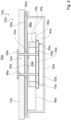
- FIG 1 shows, in particular, a cooking system 10a, which is designed, in particular, as an induction cooking system and which, in particular, has a cooking surface 52a.
- the cooking surface 52a in the present embodiment is designed as an induction cooking surface.
- the cooking system 10a has, in particular, at least one, and advantageously exactly one, support plate 12a.
- the support plate 12a is designed, in particular, as a cooktop plate.
- the support plate 12a is, in particular, part of the cooktop 52a.
- the cooktop 52a has the support plate 12a.
- the support plate 12a is provided, in particular, for supporting cooking utensils (not shown).
- the support plate 12a forms, in particular, part of a cooktop outer housing, specifically of the cooktop 52a.
- the support plate 12a in particular together with at least one outer housing unit 54a, at least substantially and advantageously completely forms the cooktop outer housing, in particular of the cooktop 52a.
- the cooking system 10a has in particular at least one and advantageously exactly one outer housing unit 54a, in particular at least the outer housing unit 54a (cf. Figure 2 ).
- the outer housing unit 54a forms, in particular, part of a hob outer housing, specifically of the hob 52a.
- the cooking system 10a has, in particular, at least one heating unit 60a.
- the cooking system 10a has, in particular, a plurality of heating units 60a. Only one of the heating units 60a is described below.
- the heating unit 60a is in an installed position, in particular, below the The heating unit 60a is arranged on the support plate 12a. In at least one assembled state, the heating unit 60a is particularly integrated into the cooking surface 52a.
- the heating unit 60a is particularly intended to heat cooking utensils placed on the support plate 12a above the heating unit 60a.
- the heating unit 60a is particularly part of the cooking surface 52a.
- the cooking surface 52a has, in particular, the heating unit 60a.
- the heating unit 60a is arranged in particular between the mounting plate 12a and at least one room divider element 80a (cf. Figure 2 ).
- the cooking system 10a has, in particular, at least one, and advantageously exactly one, room divider element 80a, in particular at least the room divider element 80a.
- the room divider element 80a divides, in particular, at least one cooking surface interior 68a into at least two sub-spaces.
- the room divider element 80a is designed as a shielding element and is provided, in particular, for electrically shielding at least one unit against electromagnetic radiation provided by the heating unit 60a.
- the cooking system 10a has in particular at least one and advantageously exactly one user interface 62a (cf. Figure 1 ).
- the user interface 62a is provided in particular for inputting and/or selecting operating parameters, such as a heating power and/or a heating power density and/or a heating zone.
- the user interface 62a is provided in particular for outputting, for example an acoustic output and advantageously an optical output, at least one operating parameter and/or at least one value of an operating parameter, in particular to an operator.
- the user interface 62a is integrated in the cooktop 52a.
- the user interface 62a is in particular part of the cooktop 52a.
- the cooktop 52a has in particular the user interface 62a.
- the cooking system 10a has, in particular, at least one and advantageously exactly one control unit 64a.
- the control unit 64a is, in particular, provided to execute actions and/or change settings depending on operating parameters entered via the user interface 62a.
- the control unit 64a controls and/or regulates, in particular, a power supply to the heating unit 60a in at least one operating state and is, in particular, designed as a heating unit control unit.
- the control unit 64a is, in particular by means of the heating unit 60a, in particular to a Heating of cooking utensils is provided, which in the operating state is arranged in particular on a side of the mounting plate 12a facing away from the control unit 64a and/or facing an operator.
- control unit 64a is particularly integrated into the hob 52a.
- the control unit 64a is particularly part of the hob 52a.
- the hob 52a particularly comprises the control unit 64a.
- the mounting plate 12a has in particular a discharge recess 14a (cf. Figures 1 and 2 ).
- an extractor fan unit 16a extracts vapors generated in the operating state from a cooking area 22a through the extractor recess 14a of the installation plate 12a.
- the cooking system 10a has in particular at least one and advantageously exactly one extractor fan unit 16a, in particular at least the extractor fan unit 16a (cf. Figures 1 to 5 ).
- the extractor fan unit 16a In the operating state, the extractor fan unit 16a is arranged, in particular, at least to a large extent and advantageously entirely below the mounting plate 12a.
- the extractor fan unit 16a In particular, in the operating state, the extractor fan unit 16a is arranged, in particular, at least to a large extent and advantageously entirely on a side of the mounting plate 12a facing away from an operator.
- the extractor fan unit 16a is, in particular, at least largely integrated into the cooktop 52a.
- the extractor fan unit 16a is, in particular, part of the cooktop 52a.
- the cooktop 52a in particular, comprises the extractor fan unit 16a.
- the exhaust fan unit 16a has at least one, and advantageously exactly one, fan wheel 18a.
- the fan wheel 18a is designed as a radial fan wheel.
- the extractor fan unit 16a In the operating state, the extractor fan unit 16a, by means of the fan wheel 18a, at least partially extracts vapors generated, in particular during the operating state, from at least one cooking area 22a through the extractor recess 14a of the support plate 12a.
- the cooking area 22a is, in particular, a spatial area extending on a side of the support plate 12a facing an operator.
- the cooking system 10a has in particular at least one protective element 56a (cf. Figures 1 and 2 ), which, in particular when viewed perpendicular to a main extension plane of the installation plate 12a, is arranged overlapping with the extraction recess 14a of the installation plate 12a.
- the protective element 56a in particular at least partially prevents the penetration of contaminants, such as dust, through the extraction recess 14a of the installation plate 12a.
- the protective element 56a is in particular part of the cooking surface 52a.
- the cooking surface 52a in particular has the protective element 56a.
- the extractor fan unit 16a has in particular at least one and advantageously exactly one drive unit 20a (cf. Figures 2 to 5 ).
- the drive unit 20a drives, in particular, the impeller 18a.
- the drive unit 20a is coupled, in particular, to the impeller 18a.
- the drive unit 20a is arranged in particular outside a space 24a which is at least partially enclosed by the fan wheel 18a (cf. Figure 2 ).
- the space 24a is at least partially delimited, in particular, by at least one base element 26a of the impeller 18a and by at least a plurality of fan blade elements 28a of the impeller 18a.
- only one of the objects present in multiple copies is provided with a reference symbol.
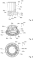
- the impeller 18a has at least one base element 26a, in particular at least the base element 26a (cf. Figure 4 ).
- the impeller 18a has at least a plurality of impeller blade elements 28a, in particular at least the plurality of impeller blade elements 28a.
- the impeller 18a has a plurality of impeller blade elements 28a.
- the impeller blade elements 28a protrude, in particular, from the base element 26a.
- the fan blade elements 28a are oriented at least substantially perpendicular to the base element 26a.
- the fan blade elements 28a protrude from the base element 26a, particularly in the operating state, in a direction facing the mounting plate 12a.
- the fan wheel 18a has at least one further base element 66a.
- the fan blade elements 28a protrude in particular from the further base element 66a.
- the fan blade elements 28a in the present exemplary embodiment are aligned at least substantially perpendicular to the further base element 66a.
- the fan blade elements 28a protrude from the further base element 66a in a direction facing away from the mounting plate 12a.
- the fan blade elements 28a are arranged between the base element 26a and the further base element 66a and, in particular, connect the base element 26a and the further base element 66a to one another.
- the fan blade elements 28a are oriented at least substantially perpendicular to a main extension plane of the mounting plate 12a.
- the fan blade elements 28a delimit the space 24a at least in a direction oriented at least substantially parallel to a main extension plane of the mounting plate 12a.
- the impeller 18a and the exhaust recess 14a are arranged, in particular, at least partially overlapping one another in the operating state.
- the impeller 18a is arranged at least partially below the exhaust recess 14a in the operating state.
- the impeller 18a has in particular at least one passage opening 30a (cf. Figures 2 and 4 ).
- the passage opening 30a of the impeller 18a enables, in particular, a passage of liquid from a suction side 32a of the impeller 18a to a pressure side 34a of the impeller 18a.
- the passage opening 30a of the impeller 18a enables, in particular, a passage of liquid, which enters the cooktop interior 68a, in particular through the exhaust recess 14a, from a side of the impeller 18a facing the installation plate 12a to a side of the impeller 18a facing away from the installation plate 12a.
- the passage opening 30a of the fan wheel 18a and the discharge recess 14a are arranged in the operating state, in particular at least partially overlapping one another.
- the drive unit 20a and the discharge recess 14a are arranged in the operating state, when viewed perpendicularly to a Main extension plane of the mounting plate 12a arranged at least partially overlapping each other.
- the drive unit 20a is arranged outside a fan housing unit 58a of the extractor fan unit 16a in the operating state.
- the extractor fan unit 16a has, in particular, at least one, and advantageously exactly one, fan housing unit 58a.
- the fan housing unit 58a is provided to at least partially accommodate the fan wheel 18a.
- the fan wheel 18a is arranged, in particular, at least partially and advantageously at least for the most part, within the fan housing unit 58a.
- the drive unit 20a is arranged, in particular, below the fan housing unit 58a.
- the drive unit 20a is coupled to the impeller 18a, in particular at an end region 36a of the impeller 18a facing away from the mounting plate 12a.
- the drive unit 20a and the impeller 18a are coupled to one another by means of at least one coupling element 70a.
- the exhaust fan unit 16a has, in particular, at least one coupling element 70a, in particular at least the coupling element 70a. In the operating state, the coupling element 70a couples, in particular, the drive unit 20a and the impeller 18a to one another.
- the coupling element 70a is connected in particular in one piece to the impeller 18a, in particular to the base element 26a of the impeller 18a.
- the impeller 18a, in particular the base element 26a of the impeller 18a, and the coupling element 70a are formed in one piece.
- the impeller 18a is in particular formed in one piece.
- the extraction recess 14a of the support plate 12a particularly enables liquid to penetrate into at least one cooktop interior 68a.
- the liquid could, for example, penetrate through the extraction recess 14a of the support plate 12a into the cooktop interior 68a due to boilover.
- the cooktop interior 68a is, in particular, at least substantially and advantageously completely defined and/or delimited by the support plate 12a and the outer housing unit 54a.
- the drive unit 20a has in particular at least one passage opening 38a (cf. Figures 2 and 5 ).
- the passage opening 38a of the drive unit 20a is provided for the passage of liquid.
- the passage opening 38a of the drive unit 20a enables the passage of liquid, which enters at least one hob interior 68a through the outlet recess 14a, from a side of the drive unit 20a facing the installation plate 12a to a side of the drive unit 20a facing away from the installation plate 12a.
- the passage opening 30a of the impeller 18a and the passage opening 38a of the drive unit 20a are arranged in the operating state, in particular at least partially, advantageously at least largely, and preferably completely overlapping with one another.
- the passage opening 30a of the impeller 18a and the passage opening 38a of the drive unit 20a communicate with one another.
- the passage opening 38a of the drive unit 20a is, in particular, part of at least one drive motor 40a of the drive unit 20a and, in particular, is at least partially enclosed by the drive motor 40a.
- the drive unit 20a has at least one drive motor 40a, in particular at least the drive motor 40a.
- the drive motor 40a has, in particular, a ring-like shape.
- the drive motor 40a in the present exemplary embodiment has the passage opening 38a of the drive unit 20a.
- the drive unit 20a has at least one rotor 42a and at least one stator 44a (cf. Figures 3 to 5 ).
- the rotor 42a is part of the drive motor 40a.
- the drive motor 40a in particular has the rotor 42a.
- the stator 44a is part of the drive motor 40a.
- the drive motor 40a in particular has the stator 44a.
- the rotor 42a has, in particular, at least a plurality of, and advantageously a multiplicity of, rotor elements 72a.
- the rotor 42a has a ring-like shape.
- the stator 44a has, in particular, at least a plurality of, and advantageously a multiplicity of, stator elements 74a.
- the stator 44a has a ring-like shape.
- a number of rotor elements 72a and a number of stator elements 74a are, in particular, different from one another. In particular, in the present embodiment, a number of rotor elements 72a is greater than a number of stator elements 74a.
- the rotor 42a and the stator 44a are arranged concentrically when viewed perpendicularly to a main extension plane of the mounting plate 12a.
- the stator 44a is arranged concentrically around the rotor 42a.
- the drive unit 20a has at least one bearing unit 76a.
- the bearing unit 76a, the rotor 42a, and the stator 44a are arranged concentrically when viewed perpendicularly to a main extension plane of the mounting plate 12a.
- the rotor 42a and the stator 44a are arranged concentrically around the bearing unit 76a.
- the bearing unit 76a comprises, in particular, a ball bearing and is designed, in particular, as a ball bearing unit.
- the bearing unit 76a has a ring-like shape.
- the bearing unit 76a has, in particular, at least one through-opening 78a (cf. Figures 2 and 5 ).
- the passage opening 78a of the bearing unit 76a is provided for the passage of liquid.
- the passage opening 78a of the bearing unit 76a and the passage opening 38a of the drive unit 20a are arranged to overlap.
- the passage opening 38a of the drive unit 20a particularly encompasses the passage opening 78a of the bearing unit 76a.
- the rotor 42a and the stator 44a drive the impeller 18a, in particular jointly.
- the rotor 42a and the stator 44a are provided jointly to drive the impeller 18a.
- the rotor 42a is in particular fixedly connected to the impeller 18a, in particular by means of the coupling element 70a.
- the rotor 42a and the base element 26a of the impeller 18a are fixedly connected to one another in the operating state.
- the extractor fan unit 16a has in particular at least one and advantageously exactly one grease filter unit 48a (cf. Figure 2 ).
- the grease filter unit 48a In the operating state, the grease filter unit 48a at least substantially absorbs grease particles dissolved in the vapors generated in at least one operating state and removes them, in particular from the vapors generated in at least one operating state, at least substantially.
- the grease filter unit 48a In the operating state, the grease filter unit 48a is arranged, in particular, at least partially within the space 24a.
- the cooking system 10a has in particular at least one and advantageously exactly one fluid collection unit 50a (cf. Figure 2 ).
- the fluid collection unit 50a collects, in particular, fluid penetrating through the discharge recess 14a of the mounting plate 12a.
- the fluid collection unit 50a is provided to receive fluid penetrating through the discharge recess 14a of the mounting plate 12a.
- the fluid collection unit 50a is arranged, in particular, on a side of the impeller 18a facing away from the mounting plate 12a.
- the fluid collection unit 50a is arranged at least partially overlapping the discharge recess 14a when viewed perpendicular to a main extension plane of the mounting plate 12a.
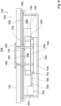
- Figure 6 shows in particular a cooking system 10b not according to the invention with an alternative cooking surface 52b.
- An extractor fan unit 16b of the cooking system 10b of the embodiment of the Figures 6 and 7 differs in particular from an extractor fan unit 16a of the cooking system 10a of the embodiment of the Figures 1 to 5 .
- the cooking system 10b comprises the extractor fan unit 16b, which in particular comprises at least one fan wheel 18b and at least one drive unit 20b for driving the fan wheel 18b.
- the fan wheel 18b is arranged, in particular, at least partially and advantageously at least to a large extent, within at least one fan housing unit 58b of the extractor fan unit 16b (see FIG. Figures 6 and 7 ).
- the drive unit 20b has, in particular, at least one drive motor 40b.
- the drive motor 40b When viewed perpendicularly to a main extension plane of a support plate 12b of the cooking system 10b, the drive motor 40b is arranged, in particular, outside the fan housing unit 58b and, in particular, outside a surface spanned by the fan housing unit 58b.
- the drive unit 20b has, in particular, at least one traction means 46b.
- the traction means 46b couples, in particular, the drive motor 40b and the impeller 18b to one another, in particular by means of at least one coupling element 70b.
- the coupling element 70b is, in particular, integrally connected to the impeller 18b and, in particular, protrudes from the fan housing unit 58b, in particular in a direction facing away from the mounting plate 12b.
- the traction means 46b is arranged, in the operating state, at least in sections below the impeller 18b and, in particular, the fan housing unit 58b.
Landscapes
- Engineering & Computer Science (AREA)
- Mechanical Engineering (AREA)
- General Engineering & Computer Science (AREA)
- Chemical & Material Sciences (AREA)
- Combustion & Propulsion (AREA)
- Physics & Mathematics (AREA)
- Electromagnetism (AREA)
- Structures Of Non-Positive Displacement Pumps (AREA)
- Baking, Grill, Roasting (AREA)
Description
- Die Erfindung betrifft ein Kochsystem nach dem Oberbegriff des Anspruchs 1.
- Aus dem Stand der Technik ist bereits ein Kochsystem mit einer Aufstellplatte und mit einer Abzugsgebläseeinheit bekannt, welche auf einer einem Bediener abgewandten Seite der Aufstellplatte angeordnet ist. Die Abzugsgebläseeinheit weist zwei Gebläseräder und eine Antriebseinheit zu einem Antrieb der Gebläseräder auf. In einem Betriebszustand saugt die Abzugsgebläseeinheit mittels des Gebläserads in dem Betriebszustand entstehende Dämpfe aus einem Kochbereich durch eine Abzugsausnehmung der Aufstellplatte hindurch teilweise ab. Die Gebläseräder sind bei einer senkrechten Betrachtung auf die Aufstellplatte seitlich neben der Abzugsausnehmung angeordnet. Die Antriebseinheit weist zwei Antriebsmotoren auf, von welchen jeweils einer einem der Gebläseräder zugeordnet ist. Der jeweilige Antriebsmotor ist innerhalb eines von dem entsprechenden Gebläserad teilweise umschlossenen Raums angeordnet.
- Aus der europäischen Patentanmeldung
EP 2 581 668 A1 ist bereits ein Kochsystem, mit einer Aufstellplatte und mit einer Abzugsgebläseeinheit, welche ein Gebläserad und eine Antriebseinheit zu einem Antrieb des Gebläserads aufweist und welche mittels des Gebläserads entstehende Dämpfe aus einem Kochbereich durch eine Abzugsausnehmung der Aufstellplatte hindurch absaugt, bekannt. Zudem sind auch aus derJP 2004 179056 A US 2007/062513 A1 und derWO 2019/068421 A1 jeweils Abzugsgebläseeinheiten bekannt. - Die Aufgabe der Erfindung besteht insbesondere darin, ein gattungsgemäßes System mit verbesserten Eigenschaften hinsichtlich einer Konstruktion bereitzustellen. Die Aufgabe wird erfindungsgemäß durch die Merkmale des Anspruchs 1 gelöst, während vorteilhafte Ausgestaltungen und Weiterbildungen der Erfindung den Unteransprüchen entnommen werden können.
- Die Erfindung geht aus von einem Kochsystem, insbesondere von einem Induktionskochsystem, mit zumindest einer Aufstellplatte und mit zumindest einer Abzugsgebläseeinheit, welche zumindest ein Gebläserad und zumindest eine Antriebseinheit zu einem Antrieb des Gebläserads aufweist und welche mittels des Gebläserads in wenigstens einem Betriebszustand entstehende Dämpfe aus zumindest einem Kochbereich durch zumindest eine Abzugsausnehmung der Aufstellplatte hindurch wenigstens teilweise absaugt.
- Es wird vorgeschlagen, dass die Antriebseinheit außerhalb eines von dem Gebläserad wenigstens teilweise umschlossenen Raums angeordnet ist.
- Durch eine derartige Ausgestaltung kann insbesondere eine optimierte Konstruktion erreicht werden. Durch die Anordnung der Antriebseinheit außerhalb des Raums kann insbesondere eine starke Beeinträchtigung der Antriebseinheit durch die abgesaugten Dämpfe und/oder ein Kontakt der Antriebseinheit mit den abgesaugten Dämpfen vermieden werden, wodurch insbesondere eine langlebige Ausgestaltung erzielt werden kann. Es kann insbesondere eine alternative und insbesondere verbesserte Ausgestaltung im Vergleich zum bekannten Stand der Technik bereitgestellt werden.
- Unter einem "Kochsystem" soll insbesondere ein System verstanden werden, welches zumindest ein Kochfeldobjekt und/oder zumindest ein Kochfeld aufweist, und welches insbesondere zusätzlich zumindest eine weitere Baueinheit aufweisen könnte, die insbesondere von einem Kochfeldobjekt und/oder von einem Kochfeld verschieden ausgebildet ist. Die weitere Baueinheit könnte beispielsweise zumindest ein Reinigungsgerät und/oder zumindest ein Kältegerät und/oder zumindest ein Mobilgerät und/oder zumindest ein Kontaktmodul und/oder zumindest eine als Arbeitsplatte ausgebildete Aufstellplatte aufweisen. Unter einem "Kochfeldobjekt" soll insbesondere zumindest ein Teil, insbesondere eine Unterbaugruppe, eines Kochfelds, insbesondere eines Induktionskochfelds, verstanden werden.
- Beispielsweise könnte das Kochsystem zumindest ein Kochfeldobjekt aufweisen, welches insbesondere eine Unterbaugruppe eines Kochfelds sein könnte. Das Kochfeldobjekt könnte beispielsweise zumindest eine Steuereinheit und/oder zumindest eine Bedienerschnittstelle und/oder zumindest eine Außengehäuseeinheit und/oder zumindest eine Heizeinheit und/oder zumindest einen Wechselrichter und/oder zumindest eine als Kochfeldplatte ausgebildete Aufstellplatte und/oder zumindest eine Abzugsgebläseeinheit aufweisen. Alternativ oder zusätzlich, insbesondere zu dem Kochfeldobjekt, könnte das Kochsystem beispielsweise zumindest ein Kochfeld und insbesondere zusätzlich zu dem Kochfeld zumindest eine weitere Baueinheit aufweisen, wie insbesondere zumindest eine als Arbeitsplatte ausgebildete Aufstellplatte.
- Insbesondere weist das Kochsystem zumindest eine Aufstellplatte, insbesondere zumindest die Aufstellplatte, auf. Die Aufstellplatte ist insbesondere zu einem Aufstellen zumindest eines Gargeschirrs und/oder zu einem Auflegen zumindest eines Garguts vorgesehen. Unter einer "Aufstellplatte" soll insbesondere zumindest eine insbesondere plattenartige Einheit verstanden werden, welche zu einem Aufstellen wenigstens eines Gargeschirrs und/oder zu einem Auflegen wenigstens eines Garguts zum Zweck der Beheizung vorgesehen ist. Die Aufstellplatte könnte beispielsweise als ein Teilbereich zumindest einer Arbeitsplatte, insbesondere zumindest einer Küchenarbeitsplatte, insbesondere des Kochsystems, ausgebildet sein. Alternativ oder zusätzlich könnte die Aufstellplatte als eine Kochfeldplatte ausgebildet sein. Die als Kochfeldplatte ausgebildete Aufstellplatte könnte insbesondere zumindest einen Teil eines Kochfeldaußengehäuses ausbilden und insbesondere gemeinsam mit zumindest einer Kochfeldgehäuseeinheit, mit welcher die als Kochfeldplatte ausgebildete Aufstellplatte in wenigstens einem montierten Zustand insbesondere verbunden sein könnte, das Kochfeldaußengehäuse wenigstens zu einem Großteil ausbilden. Die Aufstellplatte könnte beispielsweise wenigstens zu einem Großteil aus Glas und/oder aus Glaskeramik und/oder aus Neolith und/oder aus Dekton und/oder aus Holz und/oder aus Marmor und/oder aus Stein, insbesondere aus Naturstein, und/oder aus Schichtstoff und/oder aus Metall und/oder aus Kunststoff und/oder aus Keramik gebildet sein.
- Vorteilhaft weist das Kochsystem zumindest ein Kochfeld auf. Insbesondere ist die Aufstellplatte Teil des Kochfelds. Das Kochfeld weist insbesondere die Aufstellplatte auf. Das Kochfeld weist insbesondere zumindest eine Außengehäuseeinheit auf, welche insbesondere als eine Kochfeldaußengehäuseeinheit und/oder als eine Kochfeldelektronikgehäuseeinheit ausgebildet und zu einer Aufnahme zumindest einer Kochfeldelektronik vorgesehen ist.
- Unter "wenigstens zu einem Großteil" soll insbesondere zu einem Anteil, insbesondere einem Massenanteil und/oder einem Volumenanteil und/oder einem Anteil einer Anzahl, von mindestens 70 %, insbesondere von mindestens 80 %, vorteilhaft von mindestens 90 % und vorzugsweise von mindestens 95 % verstanden werden.
- Insbesondere begrenzt und/oder definiert die Aufstellplatte die Abzugsausnehmung insbesondere wenigstens zu einem Großteil und vorteilhaft vollständig. Unter einer "Abzugsausnehmung" soll insbesondere eine Ausnehmung verstanden werden, durch welche in wenigstens einem Betriebszustand entstehende Dämpfe, welche in dem Betriebszustand insbesondere aufgrund einer Beheizung zumindest eines Gargeschirrs und/oder zumindest eines Garguts entstehen, insbesondere aufgrund einer Absaugung durch die Abzugsgebläseeinheit, insbesondere hindurchtritt. Unter einer "Ausnehmung" soll insbesondere ein Loch und/oder eine Öffnung verstanden werden.
- Das Fluid könnte beispielsweise in dem Betriebszustand entstehende Dämpfe aufweisen und/oder als in dem Betriebszustand entstehende Dämpfe ausgebildet sein. Insbesondere könnte das Fluid in gasförmigem und/oder in gelöstem Zustand vorliegen und insbesondere in gasförmigem und/oder in gelöstem Zustand durch die Ausnehmung der Aufstellplatte eindringen. Das Fluid könnte vorteilhaft zumindest eine aus zumindest einem Gargeschirr austretende Flüssigkeit aufweisen und insbesondere als zumindest eine aus zumindest einem Gargeschirr austretende Flüssigkeit ausgebildet sein.
- In wenigstens einem Betriebszustand ist die Abzugsgebläseeinheit insbesondere unterhalb der Aufstellplatte und/oder auf einer einem Bediener abgewandten Seite der Aufstellplatte angeordnet. Unter einer "Abzugsgebläseeinheit" soll insbesondere eine Einheit verstanden werden, welche in wenigstens einem Betriebszustand entstehende Dämpfe aus zumindest einem Kochbereich, insbesondere durch die Abzugsausnehmung der Aufstellplatte hindurch, wenigstens teilweise absaugt und/oder filtert und welche insbesondere in wenigstens einem Betriebszustand entstehende Dämpfe aus dem Kochbereich zumindest wegtransportiert. Die Abzugsgebläseeinheit weist insbesondere zumindest eine Fettfiltereinheit auf, welche dazu vorgesehen ist, in den in wenigstens einem Betriebszustand entstehenden Dämpfen gelöste Fettpartikel wenigstens im Wesentlichen aufzunehmen und/oder aus den in wenigstens einem Betriebszustand entstehenden Dämpfen wenigstens im Wesentlichen zu entfernen. Insbesondere ist das Gebläserad dazu vorgesehen, in wenigstens einem Betriebszustand zumindest einen Ansaugstrom für in wenigstens einem Betriebszustand entstehende Dämpfe bereitzustellen und insbesondere die abgesaugten Dämpfe aus dem Kochbereich zumindest wegzutransportieren. Beispielsweise könnte die Abzugsgebläseeinheit dazu vorgesehen sein, die in dem Betriebszustand entstehenden Dämpfe aus dem Kochbereich und zusätzlich aus einem Kochraum abzuleiten und beispielsweise zumindest einer Abluftleitung zuzuführen. Alternativ könnte die Abzugsgebläseeinheit insbesondere dazu vorgesehen sein, die in dem Betriebszustand entstehenden Dämpfe aus dem Kochbereich in zumindest einen weiteren Teilbereich des Kochraums zu transportieren.
- Insbesondere könnten die in dem Betriebszustand entstehenden Dämpfe in gasförmigem und/oder in gelöstem Zustand vorliegen und insbesondere in gasförmigem und/oder in gelöstem Zustand durch die Abzugsausnehmung der Aufstellplatte eindringen und/oder in zumindest einen Kochfeldinnenraum gelangen.
- Unter einem "Kochbereich" soll insbesondere ein Teilbereich eines Kochraums verstanden werden, in welchem in wenigstens einem Betriebszustand ein Garvorgang erfolgt und in welchem insbesondere bei dem Garvorgang entstehendes Fluid und/oder bei dem Garvorgang entstehende Dämpfe aus einem beheizten Gargeschirr entweichen und welcher sich vorteilhaft in einer Einbaulage wenigstens zu einem Großteil oberhalb der Aufstellplatte und/oder auf einer einem Bediener zugewandten Seite der Aufstellplatte erstreckt. Unter einem "Kochraum" soll insbesondere ein Raum, insbesondere ein Zimmer, verstanden werden, in welchem ein Kochsystem und/oder ein Kochfeld angeordnet ist.
- Das Gebläserad weist insbesondere einen Durchmesser von mindestens 210 mm, insbesondere von mindestens 220 mm, vorteilhaft von mindestens 250 mm, besonders vorteilhaft von mindestens 270 mm, vorzugsweise von mindestens 290 mm und besonders bevorzugt von mindestens 300 mm auf. Dadurch kann insbesondere ein geringer von dem Gebläserad in dem Betriebszustand erzeugter Geräuschpegel erreicht werden, welcher insbesondere einen Wert von maximal 20 dB, insbesondere von maximal 18 dB, vorteilhaft von maximal 16 dB, besonders vorteilhaft von maximal 14 dB und vorzugsweise von maximal 12 dB annehmen könnte.
- Unter einer "Antriebseinheit" soll insbesondere eine Einheit verstanden werden, welche insbesondere zumindest einen Antriebsmotor aufweist und insbesondere in wenigstens einem Betriebszustand, insbesondere mittels des Antriebsmotors, zumindest eine Antriebskraft zu einem, insbesondere mechanischen, Antrieb des Gebläserads bereitstellt. Insbesondere versetzt die Antriebseinheit, insbesondere mittels des Antriebsmotors, insbesondere in wenigstens einem Betriebszustand, das Gebläserad in zumindest eine Rotationsbewegung. Die Antriebseinheit, insbesondere der Antriebsmotor der Antriebseinheit, sind, insbesondere in wenigstens einem Betriebszustand, insbesondere drehfest miteinander verbunden und/oder drehfest aneinander gekoppelt. Der Antriebsmotor könnte vorteilhaft ein Elektromotor sein.
- In einer Einbaulage ist die Abzugsgebläseeinheit insbesondere unterhalb der Aufstellplatte angeordnet. Insbesondere weist das Kochsystem zumindest eine Außengehäuseeinheit auf, welche insbesondere als eine Kochfeldaußengehäuseeinheit und/oder als eine Kochfeldelektronikgehäuseeinheit ausgebildet ist und vorteilhaft gemeinsam mit der Aufstellplatte ein Kochfeldaußengehäuse wenigstens im Wesentlichen definiert. Beispielsweise könnte die Abzugsgebläseeinheit in einer Einbaulage unterhalb der Außengehäuseeinheit angeordnet und insbesondere an zumindest einer Unterseite und/oder an zumindest einem Gehäuseboden der Außengehäuseeinheit befestigt sein. Die Abzugsgebläseeinheit könnte in einer Einbaulage insbesondere wenigstens zu einem Großteil innerhalb der Außengehäuseeinheit angeordnet sein. Unter einer "Außengehäuseeinheit" soll insbesondere eine Einheit verstanden werden, welche in wenigstens einem montierten Zustand zumindest einen, insbesondere als Hohlraum ausgebildeten, Aufnahmeraum zu einer Aufnahme und/oder zu einer Lagerung wenigstens eines Kochfeldbauteils wenigstens teilweise begrenzt und/oder definiert. Das Kochfeldbauteil könnte beispielsweise zumindest eine Heizeinheit und/oder zumindest eine Steuereinheit und/oder zumindest eine Versorgungseinheit und/oder zumindest eine Bedienerschnittstelle und/oder zumindest eine Versorgungselektronikeinheit aufweisen.
- Unter der Wendung, dass eine Einheit einen Aufnahmeraum "wenigstens teilweise" begrenzt und/oder definiert, soll insbesondere verstanden werden, dass die Einheit den Aufnahmeraum alleine oder gemeinsam mit zumindest einer weiteren Einheit, wie beispielsweise mit der Aufstellplatte, begrenzt und/oder definiert. Insbesondere begrenzen die Außengehäuseeinheit und die Aufstellplatte insbesondere gemeinsam den Aufnahmeraum insbesondere wenigstens im Wesentlichen und vorteilhaft vollständig. Die Außengehäuseeinheit nimmt in dem montierten Zustand insbesondere eine Gewichtskraft von zumindest einem Kochfeldbauteil wenigstens zu einem Großteil auf und/oder überträgt die Gewichtskraft an zumindest eine weitere Einheit, wie beispielsweise an die Aufstellplatte. Vorteilhaft ist die Außengehäuseeinheit als eine einteilige und/oder einstückige Gehäusewanne ausgebildet. Die Außengehäuseeinheit ist insbesondere als eine Kochfeldaußengehäuseeinheit und vorteilhaft als eine Kochfeldelektronikgehäuseeinheit ausgebildet.
- Unter "einstückig" soll insbesondere zumindest stoffschlüssig verbunden verstanden werden, beispielsweise durch einen Schweißprozess, einen Klebeprozess, einen Anspritzprozess und/oder einen anderen, dem Fachmann als sinnvoll erscheinenden Prozess, und/oder vorteilhaft in einem Stück geformt verstanden werden, wie beispielsweise durch eine Herstellung aus einem Guss und/oder durch eine Herstellung in einem Ein- oder Mehrkomponentenspritzverfahren und vorteilhaft aus einem einzelnen Rohling.
- Die Außengehäuseeinheit weist insbesondere zumindest einen Gehäuseboden auf, welcher in wenigstens einem Betriebszustand insbesondere eine einem Bediener abgewandte Seite der Außengehäuseeinheit definiert und/oder ausbildet. In wenigstens einem Betriebszustand beträgt ein Abstand zwischen dem Gehäuseboden und der Aufstellplatte, welcher insbesondere senkrecht zu dem Gehäuseboden und zu der Aufstellplatte gemessen ist, beispielsweise maximal 500 mm, insbesondere maximal 400 mm, vorteilhaft maximal 350 mm, besonders vorteilhaft maximal 300 mm, vorzugsweise maximal 250 mm und besonders bevorzugt maximal 230 mm, wodurch insbesondere eine kompakte Ausgestaltung erzielt werden kann.
- Beispielsweise könnte die Aufstellplatte und/oder das die Aufstellplatte aufweisende Kochfeld, insbesondere bei einer senkrechten Betrachtung auf eine Haupterstreckungsebene der Aufstellplatte, eine maximale Erstreckung, insbesondere eine Breitenerstreckung und/oder eine Längserstreckung, von maximal 100 cm, insbesondere von maximal 90 cm, vorteilhaft von maximal 80 cm, besonders vorteilhaft von maximal 70 cm, vorzugsweise von maximal 65 cm und besonders bevorzugt von maximal 60 cm aufweisen, wodurch insbesondere selbst kleine Kochfelder mit einer Abzugsgebläseeinheit ausgestattet werden können. Unter einer "Haupterstreckungsebene" eines Objekts soll insbesondere eine Ebene verstanden werden, welche parallel zu einer größten Seitenfläche eines kleinsten gedachten geometrischen Quaders ist, welcher das Objekt gerade noch vollständig umschließt, und insbesondere durch den Mittelpunkt des Quaders verläuft.
- Unter der Wendung, dass die Abzugsgebläseeinheit in wenigstens einem Betriebszustand entstehende Dämpfe aus zumindest einem Kochbereich "wenigstens teilweise" absaugt, soll insbesondere verstanden werden, dass die Abzugsgebläseeinheit in dem Betriebszustand entstehende Dämpfe aus dem Kochbereich, insbesondere durch die Abzugsausnehmung der Aufstellplatte hindurch, zu einem Volumenanteil und/oder Massenanteil, insbesondere der gesamten in dem Betriebszustand entstehenden Dämpfe, von mindestens 20 %, insbesondere von mindestens 40 %, vorteilhaft von mindestens 60 %, besonders vorteilhaft von mindestens 70 %, vorzugsweise von mindestens 80 % und besonders bevorzugt von mindestens 90 % absaugt.
- Unter einem von dem Gebläserad "wenigstens teilweise" umschlossenen Raum, soll insbesondere verstanden werden, dass das Gebläserad den Raum in zumindest einer Ebene umschließt und insbesondere in zumindest einer weiteren Ebene, insbesondere ausschließlich, teilweise umschließen könnte. Die Ebene könnte in dem Betriebszustand beispielsweise wenigstens im Wesentlichen parallel zu einer Haupterstreckungsebene der Aufstellplatte ausgerichtet sein. Die Ebene könnte in dem Betriebszustand beispielsweise wenigstens im Wesentlichen senkrecht zu einer Haupterstreckungsebene der Aufstellplatte ausgerichtet sein.
- Das Gebläserad umschließt den Raum insbesondere in zumindest einer Ebene, welche insbesondere wenigstens im Wesentlichen parallel zu einer Haupterstreckungsebene der Aufstellplatte ausgerichtet ist, über einen Winkelbereich von mindestens 90 °, insbesondere von mindestens 180 °, vorteilhaft von mindestens 270 °, besonders vorteilhaft von mindestens 300 °, vorzugsweise von mindestens 330 ° und besonders bevorzugt von mindestens 350 °. Beispielsweise könnte das Gebläserad den Raum vollständig umschließen und insbesondere eine zylinderartige Gestalt aufweisen. Vorteilhaft umschließt das Gebläserad den Raum teilweise und weist insbesondere eine zylindermantelartige Gestalt auf. Der Raum ist insbesondere an einer der Aufstellplatte zugewandten Seite des Gebläserads und/oder an einer der Aufstellplatte abgewandten Seite des Gebläserads, insbesondere durch das Gebläserad, unbegrenzt.
- Unter "im Wesentlichen parallel" soll hier insbesondere eine Ausrichtung einer Richtung relativ zu einer Bezugsrichtung, insbesondere in einer Ebene, verstanden werden, wobei die Richtung gegenüber der Bezugsrichtung eine Abweichung insbesondere maximal 8 °, vorteilhaft maximal 5 ° und besonders vorteilhaft maximal 2 ° aufweist. Der Ausdruck "im Wesentlichen senkrecht" soll hier insbesondere eine Ausrichtung einer Richtung relativ zu einer Bezugsrichtung definieren, wobei die Richtung und die Bezugsrichtung, insbesondere in einer Ebene betrachtet, einen Winkel von 90 ° einschließen und der Winkel eine maximale Abweichung von insbesondere maximal 8 °, vorteilhaft maximal 5 ° und besonders vorteilhaft maximal 2° aufweist.
- Unter "vorgesehen" soll insbesondere speziell ausgelegt und/oder ausgestattet verstanden werden. Darunter, dass ein Objekt zu einer bestimmten Funktion vorgesehen ist, soll insbesondere verstanden werden, dass das Objekt diese bestimmte Funktion in zumindest einem Anwendungs- und/oder Betriebszustand erfüllt und/oder ausführt.
- Erfindungsgemäß weist das Gebläserad zumindest ein Basiselement auf, von welchem zumindest eine Mehrzahl an Gebläseflügelelementen des Gebläserads absteht, welche den Raum wenigstens teilweise umschließen und/oder begrenzen. Insbesondere weist das Gebläserad zumindest eine Mehrzahl an Gebläseflügelelementen, vorteilhaft zumindest die Mehrzahl an Gebläseflügelelementen, auf. Unter einer "Mehrzahl" soll insbesondere eine Anzahl von mindestens vier, insbesondere von mindestens fünf, vorteilhaft von mindestens sechs, besonders vorteilhaft von mindestens acht, vorzugsweise von mindestens zehn und besonders bevorzugt von mindestens zwölf verstanden werden. Das Gebläserad weist vorteilhaft eine Vielzahl an Gebläseflügelelementen auf. Die Gebläseflügelelemente sind insbesondere wenigstens im Wesentlichen parallel zueinander ausgerichtet. Beispielsweise könnten die Gebläseflügelelemente wenigstens im Wesentlichen parallel zu einer Haupterstreckungsebene der Aufstellplatte ausgerichtet sein und insbesondere den Raum in zumindest einer Richtung wenigstens teilweise umschließen, welche insbesondere wenigstens im Wesentlichen senkrecht zu einer Haupterstreckungsebene der Aufstellplatte ausgerichtet sein könnte. Die Gebläseflügelelemente könnten beispielsweise schräg relativ zu einer Haupterstreckungsebene der Aufstellplatte ausgerichtet sein und insbesondere den Raum in zumindest einer Richtung wenigstens teilweise umschließen, welche insbesondere schräg relativ zu einer Haupterstreckungsebene der Aufstellplatte ausgerichtet sein könnte. Vorteilhaft könnten die Gebläseflügelelemente wenigstens im Wesentlichen senkrecht zu einer Haupterstreckungsebene der Aufstellplatte ausgerichtet sein und insbesondere den Raum in zumindest einer Richtung wenigstens teilweise umschließen, welche insbesondere wenigstens im Wesentlichen parallel zu einer Haupterstreckungsebene der Aufstellplatte ausgerichtet sein könnte. Bei einer Betrachtung des Basiselements in einer Richtung, welche insbesondere senkrecht zu einer Haupterstreckungsebene der Aufstellplatte ausgerichtet ist, könnte das Basiselement insbesondere eine ovalartige Gestalt, vorteilhaft eine ellipsenartige Gestalt und/oder eine kreisartige Gestalt aufweisen. Vorzugsweise weist das Basiselement eine ringartige Gestalt auf. Insbesondere dient das Basiselement als eine Basis zu einer Anordnung und/oder Befestigung der Gebläseflügelelemente. Beispielweise könnte das Basiselement auf einer der Aufstellplatte zugewandten Seite der Gebläseflügelelemente angeordnet sein. Alternativ oder zusätzlich könnte das Basiselement beispielsweise auf einer der Aufstellplatte abgewandten Seite der Gebläseflügelelemente angeordnet sein. Dadurch kann insbesondere ein konstruktiv optimiertes Basiselement bereitgestellt werden.
- Zudem wird vorgeschlagen, dass das Gebläserad als ein Radiallüfterrad ausgebildet und insbesondere Teil von zumindest einem Radiallüfter, insbesondere der Abzugsgebläseeinheit, ist. Dadurch kann insbesondere ein hoher Wirkungsgrad und/oder eine geringe Geräuschentwicklung, insbesondere in einem Vergleich zu einem Axiallüfter, erreicht werden.
- Weiterhin wird vorgeschlagen, dass das Gebläserad zumindest eine Durchtrittsöffnung aufweist, welche ein Passieren von Flüssigkeit von einer Saugseite des Gebläserads zu einer Druckseite des Gebläserads ermöglicht. Insbesondere umschießen und/oder begrenzen die Gebläseflügelelemente die Durchtrittsöffnung des Gebläserads wenigstens teilweise. Die Durchtrittsöffnung des Gebläserads ist insbesondere als eine Gebläseraddurchtrittsöffnung ausgebildet. Der Begriff "Durchtrittsöffnung des Gebläserads" könnte beispielsweise durch den Begriff "Gebläseraddurchtrittsöffnung" ersetzt werden. Insbesondere ermöglicht die Durchtrittsöffnung des Gebläserads in wenigstens einem Betriebszustand ein Passieren von Flüssigkeit von einer der Aufstellplatte zugewandten Seite des Gebläserads zu einer der Aufstellplatte abgewandten Seite des Gebläserads. Die Saugseite des Gebläserads ist in wenigstens einem Betriebszustand insbesondere auf einer der Aufstellplatte zugewandten Seite des Gebläserads angeordnet. Die Druckseite des Gebläserads ist in wenigstens einem Betriebszustand insbesondere auf einer der Aufstellplatte abgewandten Seite des Gebläserads angeordnet. Das Gebläserad weist insbesondere eine zylindermantelartige Gestalt auf. Dadurch kann insbesondere eine möglichst kurze von der Flüssigkeit zurückzulegende Wegstrecke bis zu einem Erreichen einer Fluidsammeleinheit erzielt werden, wodurch insbesondere eine geringe Gefahr einer Verschmutzung und/oder Beschädigung von Komponenten des Kochfelds erreicht werden kann. Es kann insbesondere auf eine zusätzliche Führungseinheit zu einer Führung der Flüssigkeit zu der Fluidsammeleinheit verzichtet werden, wodurch insbesondere eine preisgünstige Ausgestaltung erzielt werden kann.
- Der Raum ist in wenigstens einem Betriebszustand insbesondere zu einer Durchführung von Fluid, insbesondere von einer der Aufstellplatte zugewandten Seite des Gebläserads zu einer der Aufstellplatte abgewandten Seite des Gebläserads, vorgesehen. Insbesondere ist der Raum zu einem Anteil, insbesondere zu einem Volumenanteil, von mindestens 60 %, insbesondere von mindestens 70 %, vorteilhaft von mindestens 80 %, besonders vorteilhaft von mindestens 85 % und vorzugsweise von mindestens 90 % frei von Komponenten, insbesondere der Abzugsgebläseeinheit und/oder des Kochfelds. Dadurch kann insbesondere eine optimierte Konstruktion und/oder ein ungestörter Betrieb des Gebläserads ermöglicht werden.
- Beispielsweise könnte die Antriebseinheit, insbesondere in wenigstens einem Betriebszustand, an einem der Aufstellplatte zugewandten Endbereich des Gebläserads an das Gebläserad gekoppelt sein. Vorzugsweise ist die Antriebseinheit, insbesondere in wenigstens einem Betriebszustand, an einem der Aufstellplatte abgewandten Endbereich des Gebläserads an das Gebläserad gekoppelt. Dadurch kann die Antriebseinheit insbesondere optimal positioniert werden. Es kann insbesondere eine Beeinträchtigung der Antriebseinheit, insbesondere durch von dem Gebläserad durch die Abzugsausnehmung abgesaugte Dämpfe, vermieden werden.
- Zudem wird vorgeschlagen, dass die Antriebseinheit zumindest eine Durchtrittsöffnung aufweist, welche zu einem Passieren von Flüssigkeit vorgesehen ist. Die Durchtrittsöffnung der Antriebseinheit ist insbesondere als eine Antriebseinheitdurchtrittsöffnung ausgebildet. Der Begriff "Durchtrittsöffnung der Antriebseinheit" könnte beispielsweise durch den Begriff "Antriebseinheitdurchtrittsöffnung" ersetzt werden. Insbesondere ermöglicht die Durchtrittsöffnung der Antriebseinheit in wenigstens einem Betriebszustand ein Passieren von Flüssigkeit von einer der Aufstellplatte zugewandten Seite der Antriebseinheit zu einer der Aufstellplatte abgewandten Seite der Antriebseinheit. Dadurch kann insbesondere auf konstruktiv einfache Weise durch die Abzugsausnehmung eindringende Flüssigkeit die Antriebseinheit, insbesondere die Antriebseinheit und das Gebläserad, vorteilhaft die Abzugsgebläseeinheit, passieren, wodurch insbesondere eine Beschädigung der Antriebseinheit durch die Flüssigkeit vermieden und/oder eine langlebige Ausgestaltung erzielt werden kann.
- Weiterhin wird vorgeschlagen, dass die Durchtrittsöffnung des Gebläserads und die Durchtrittsöffnung der Antriebseinheit miteinander kommunizieren. Insbesondere sind die Durchtrittsöffnung des Gebläserads und die Durchtrittsöffnung der Antriebseinheit wenigstens abschnittsweise, insbesondere wenigstens zu einem Großteil und vorteilhaft vollständig fluchtend angeordnet. Die Durchtrittsöffnung des Gebläserads und die Durchtrittsöffnung der Antriebseinheit sind bei einer Betrachtung in einer Richtung, welche insbesondere senkrecht zu einer Haupterstreckungsebene der Aufstellplatte ausgerichtet ist, wenigstens abschnittsweise, insbesondere wenigstens zu einem Großteil und vorteilhaft vollständig überlappend angeordnet. Dadurch kann insbesondere ein ungehindertes Passieren von durch die Abzugsausnehmung eindringender Flüssigkeit in einen der Aufstellplatte abgewandten Bereich des Gebläserads und/oder der Antriebseinheit ermöglicht werden, wodurch insbesondere auf eine zusätzliche Führungseinheit zu einer Führung der Flüssigkeit verzichtet und/oder geringe Kosten erzielt werden können/kann.
- Beispielsweise könnte die Antriebseinheit zumindest einen Antriebsmotor und zumindest ein Zugmittel aufweisen, welches insbesondere den Antriebsmotor und das Gebläserad miteinander koppeln und insbesondere die Durchtrittsöffnung der Antriebseinheit wenigstens teilweise umgeben und/oder definieren könnte. Vorzugsweise weist die Antriebseinheit zumindest einen Antriebsmotor auf, welcher eine ringartige Gestalt aufweist und welcher die Durchtrittsöffnung der Antriebseinheit aufweist. Insbesondere umschließt und/oder definiert und/oder begrenzt der Antriebsmotor die Durchtrittsöffnung der Antriebseinheit wenigstens teilweise. Dadurch kann insbesondere eine konstruktiv optimierte und/oder kompakte Ausgestaltung erreicht werden.
- Zudem weist die Antriebseinheit, insbesondere der Antriebsmotor der Antriebseinheit, erfindungsgemäß zumindest einen Rotor und zumindest einen Stator auf, welche jeweils eine ringartige Gestalt aufweisen und gemeinsam zu einem Antrieb des Gebläserads vorgesehen sind. Insbesondere weist der Stator zumindest eine Mehrzahl an und vorzugsweise eine Vielzahl an Statorelementen auf. Der Rotor weist insbesondere zumindest eine Mehrzahl an und vorzugsweise eine Vielzahl an Rotorelementen auf. Vorteilhaft sind eine Anzahl an Statorelementen und eine Anzahl an Rotorelementen voneinander verschieden. Die Rotorelemente und die Statorelemente sind insbesondere versetzt relativ zueinander angeordnet. Beispielsweise könnte der Stator, insbesondere pro Statorelement, zumindest einen Elektromagneten und der Rotor, insbesondere pro Rotorelement, insbesondere zumindest einen Permanentmagneten aufweisen. Beispielsweise könnte der Rotor, insbesondere pro Rotorelement, zumindest einen Elektromagneten und der Stator, insbesondere pro Statorelement, insbesondere zumindest einen Permanentmagneten aufweisen. Dadurch kann das Gebläserad insbesondere auf zuverlässige Art und Weise angetrieben werden, wodurch insbesondere ein reibungsloser Betrieb und/oder ein hoher Bedienkomfort ermöglicht werden kann.
- Weiterhin sind der Rotor und das Basiselement, insbesondere in wenigstens einem Betriebszustand, erfindungsgemäß fest und/oder drehfest miteinander verbunden. Insbesondere sind der Rotor und das Basiselement, insbesondere in wenigstens einem Betriebszustand, wenigstens abschnittsweise in direktem Kontakt miteinander angeordnet. Der Rotor und das Basiselement könnten beispielsweise mittels zumindest einer kraftschlüssigen und/oder mittels zumindest einer formschlüssigen Verbindung und/oder mittels zumindest einer stoffschlüssigen Verbindung fest und/oder drehfest miteinander verbunden sein. Dadurch kann insbesondere eine hohe Stabilität und/oder eine optimale Kopplung zwischen dem Rotor und dem Basiselement bereitgestellt werden, wodurch insbesondere ein hoher Bedienkomfort ermöglicht werden kann.
- In einer nicht erfindungsgemäßen Ausgestaltung weist die Antriebseinheit zumindest einen Antriebsmotor und zumindest ein Zugmittel auf, welches insbesondere zu einem Antrieb durch den Antriebsmotor vorgesehen ist und welches den Antriebsmotor und das Gebläserad miteinander koppelt. Die Antriebseinheit ist insbesondere dazu vorgesehen, zumindest ein Drehmoment zwischen zumindest zwei Wellen, insbesondere zwischen zumindest einer Welle des Antriebsmotors und zumindest einer Welle des Gebläserads, zumindest mittels des die Wellen umschlingenden Zugmittels zu übertragen. Beispielsweise könnte das Zugmittel den Antriebsmotor und das Gebläserad kraftschlüssig und/oder formschlüssig miteinander koppeln. Die Antriebseinheit könnte, insbesondere mittels des Zugmittels, zu einer kraftschlüssigen und/oder formschlüssigen Übertragung des Drehmoments zwischen den Wellen vorgesehen sein. Die Antriebseinheit könnte beispielsweise zumindest einen Kettentrieb und/oder zumindest einen Zahnriementrieb und/oder zumindest einen Flachriementrieb und/oder zumindest einen Keilriementrieb und/oder zumindest einen Rundriementrieb aufweisen und insbesondere als solcher ausgebildet sein. In wenigstens einem Betriebszustand treibt die Antriebseinheit das Gebläserad, insbesondere mittels des Antriebsmotors und des Zugmittels, mechanisch an. Dadurch kann insbesondere auf konstruktiv simple und/oder einfache Weise ein Antrieb des Gebläserads ermöglicht werden, wodurch insbesondere geringe Kosten und/oder eine zuverlässige Ausgestaltung erzielt werden können/kann.
- Der Raum könnte beispielsweise vollständig frei von Komponenten des Kochfelds und/oder der Abzugsgebläseeinheit sein. Vorzugsweise weist die Abzugsgebläseeinheit zumindest eine Fettfiltereinheit, insbesondere zumindest die Fettfiltereinheit, auf, welche wenigstens abschnittsweise innerhalb des Raums angeordnet ist. Die Fettfiltereinheit ragt insbesondere ausgehend von einer Saugseite des Gebläserads, insbesondere ausgehend von der Saugseite des Gebläserads, zumindest in den Raum hinein und erstreckt sich vorteilhaft durch den Raum hindurch. Insbesondere ist zumindest ein Abschnitt der Fettfiltereinheit auf einer Saugseite des Gebläserads, insbesondere auf der Saugseite des Gebläserads, und zumindest ein weiterer Abschnitt der Fettfiltereinheit auf einer Druckseite des Gebläserads, insbesondere auf der Druckseite des Gebläserads, angeordnet. Der Abschnitt des Gebläserads und der weitere Abschnitt des Gebläserads sind insbesondere durch zumindest einen sich innerhalb des Raums befindlichen Abschnitt der Fettfiltereinheit miteinander verbunden. Dadurch kann insbesondere in den in dem Betriebszustand entstehenden Dämpfen gelöste Fettpartikel optimal ausgefiltert werden, wodurch insbesondere ein hoher Hygienestandard und/oder ein hoher Bedienkomfort erreicht werden kann.
- Bei einer senkrechten Betrachtung auf eine Haupterstreckungsebene der Aufstellplatte könnten das Gebläserad und die Abzugsausnehmung in dem Betriebszustand beispielsweise beabstandet zueinander angeordnet sein. Beispielsweise könnte die Abzugsgebläseeinheit, insbesondere zusätzlich zu dem Gebläserad, zumindest ein weiteres Gebläserad aufweisen, welches bei einer senkrechten Betrachtung auf eine Haupterstreckungsebene der Aufstellplatte insbesondere auf einer dem Gebläserad abgewandten Seite der Abzugsausnehmung angeordnet sein könnte. Vorzugsweise sind das Gebläserad und die Abzugsausnehmung in dem Betriebszustand bei einer senkrechten Betrachtung auf eine Haupterstreckungsebene der Aufstellplatte wenigstens teilweise miteinander überlappend angeordnet. Die Abzugsgebläseeinheit weist, insbesondere genau, ein, insbesondere einziges, Gebläserad auf. Insbesondere ist das Gebläserad wenigstens im Wesentlichen und vorteilhaft vollständig mittig unterhalb der Abzugsausnehmung angeordnet. Unter der Wendung, dass das Gebläserad und die Abzugsausnehmung in dem Betriebszustand bei einer senkrechten Betrachtung auf eine Haupterstreckungsebene der Aufstellplatte "wenigstens teilweise" miteinander überlappend angeordnet sind, soll insbesondere verstanden werden, dass zumindest ein Teilbereich des Gebläserads und zumindest ein Teilbereich der Abzugsausnehmung in dem Betriebszustand bei einer senkrechten Betrachtung auf eine Haupterstreckungsebene der Aufstellplatte miteinander überlappend angeordnet sind. Beispielsweise könnte das Gebläserad zumindest einen weiteren Teilbereich aufweisen, welcher in dem Betriebszustand bei einer senkrechten Betrachtung auf eine Haupterstreckungsebene der Aufstellplatte beabstandet zu der Abzugsausnehmung und/oder außerhalb einer von der Abzugsausnehmung aufgespannten Flächenerstreckung angeordnet sein könnte. Beispielsweise könnte die Abzugsausnehmung zumindest einen weiteren Teilbereich aufweisen, welcher in dem Betriebszustand bei einer senkrechten Betrachtung auf eine Haupterstreckungsebene der Aufstellplatte beabstandet zu dem Gebläserad und/oder außerhalb einer von dem Gebläserad aufgespannten Flächenerstreckung angeordnet sein könnte. Bei einer senkrechten Betrachtung auf eine Haupterstreckungsebene der Aufstellplatte ist die Abzugsausnehmung in dem Betriebszustand insbesondere zu einem Anteil, insbesondere zu einem Flächenanteil, von mindestens 50 %, insbesondere von mindestens 60 %, vorteilhaft von mindestens 70 %, besonders vorteilhaft von mindestens 80 %, vorzugsweise von mindestens 90 % und besonders bevorzugt von mindestens 95 % überlappend mit dem Gebläserad und insbesondere innerhalb einer von dem Gebläserad aufgespannten Flächenerstreckung angeordnet. Dadurch kann insbesondere eine kurze von den abgesaugten, in dem Betriebszustand entstehenden Dämpfen ermöglicht werden, wodurch insbesondere eine kompakte Ausgestaltung erzielt werden kann. Insbesondere kann auf eine komplizierte Ausgestaltung einer zusätzlichen Führungseinheit zu einer Führung der abgesaugten, in dem Betriebszustand entstehenden Dämpfe verzichtet werden, wodurch insbesondere eine geringe Bauteilevielfalt und/oder eine geringe Lagerhaltung erreicht werden kann.
- Ferner wird vorgeschlagen, dass die Abzugsgebläseeinheit zumindest eine Fluidsammeleinheit aufweist, welche auf einer der Aufstellplatte abgewandten Seite des Gebläserads angeordnet ist. Bei einer senkrechten Betrachtung auf eine Haupterstreckungsebene der Aufstellplatte sind die Fluidsammeleinheit und die Abzugsausnehmung insbesondere wenigstens teilweise miteinander überlappend angeordnet. Unter einer "Fluidsammeleinheit" soll insbesondere eine Einheit verstanden werden, welche zumindest einen Fluidaufnahmeraum wenigstens teilweise, insbesondere wenigstens zu einem Großteil und vorteilhaft vollständig begrenzt und/oder definiert und welche insbesondere in dem Betriebszustand durch die Abzugsausnehmung eindringendes Fluid wenigstens zu einem Großteil sammelt und/oder aufnimmt. Beispielsweise könnte die Fluidsammeleinheit eine quaderartige Gestalt aufweisen. Die Fluidsammeleinheit weist insbesondere zumindest einen Fluideingang auf, durch welchen hindurch in dem Betriebszustand insbesondere das, insbesondere durch die Abzugsausnehmung in zumindest einen Kochfeldinnenraum eindringende und/oder sich in zumindest einem Kochfeldinnenraum befindliche, Fluid, insbesondere in den Fluidaufnahmeraum, eintritt. Insbesondere weist die Fluidsammeleinheit zumindest einen Fluidausgang auf, durch welchen hindurch in dem Betriebszustand insbesondere das, sich insbesondere in dem Fluidaufnahmeraum befindliche, Fluid, insbesondere aus dem Fluidaufnahmeraum, austritt. Das Fluid könnte beispielsweise in dem Betriebszustand entstehende Dämpfe aufweisen und/oder als in dem Betriebszustand entstehende Dämpfe ausgebildet sein. Insbesondere könnte das Fluid in gasförmigem und/oder in gelöstem Zustand vorliegen und insbesondere in gasförmigem und/oder in gelöstem Zustand durch die Abzugsausnehmung der Aufstellplatte eindringen. Das Fluid könnte vorteilhaft zumindest eine aus zumindest einem Gargeschirr austretende Flüssigkeit aufweisen und insbesondere als zumindest eine aus zumindest einem Gargeschirr austretende Flüssigkeit ausgebildet sein. Das Fluid ist insbesondere als eine Flüssigkeit ausgebildet und/oder weist insbesondere zumindest eine Flüssigkeit auf. Dadurch kann insbesondere ein hoher Hygienestandard erreicht und/oder eine Beschädigung von Komponenten, insbesondere des Kochfelds, durch eindringendes Fluid vermieden werden, wodurch insbesondere eine langlebige Ausgestaltung erzielt werden kann.
- Zudem wird vorgeschlagen, dass das Kochsystem zumindest ein Kochfeld, insbesondere zumindest das Kochfeld, aufweist, welches zumindest die Abzugsgebläseeinheit aufweist. Das Kochfeld ist insbesondere als ein Induktionskochfeld ausgebildet. Die Abzugsgebläseeinheit ist insbesondere in wenigstens einem Betriebszustand wenigstens teilweise, insbesondere wenigstens zu einem Großteil und vorteilhaft vollständig in dem Kochfeld, insbesondere in der Außengehäuseeinheit des Kochfelds, integriert. Dadurch kann insbesondere auf eine separate Dunstabzugshaube verzichtet werden, wodurch insbesondere eine geringe Bauteilevielfalt und/oder eine geringe Lagerhaltung erzielt werden kann. Durch die Integration der Abzugsgebläseeinheit in dem Kochfeld kann die Abzugsgebläseeinheit insbesondere zu einer Kühlung von Komponenten des Kochfelds, wie beispielsweise einer Steuereinheit und/oder einer Leistungselektronik, verwendet werden, wodurch insbesondere auf eine zusätzliche Kühlungseinheit verzichtet werden kann. Hierdurch kann insbesondere ein geringer Geräuschpegel in dem Betriebszustand und/oder eine preisgünstige Ausgestaltung erzielt werden.
- Das Kochsystem soll hierbei nicht auf die oben beschriebene Anwendung und Ausführungsform beschränkt sein. Insbesondere kann das Kochsystem zu einer Erfüllung einer hierin beschriebenen Funktionsweise eine von einer hierin genannten Anzahl von einzelnen Elementen, Bauteilen und Einheiten abweichende Anzahl aufweisen.
- Weitere Vorteile ergeben sich aus der folgenden Zeichnungsbeschreibung. In der Zeichnung sind Ausführungsbeispiele der Erfindung dargestellt. Die Zeichnung, die Beschreibung und die Ansprüche enthalten zahlreiche Merkmale in Kombination. Der Fachmann wird die Merkmale zweckmäßigerweise auch einzeln betrachten und zu sinnvollen weiteren Kombinationen zusammenfassen.
- Es zeigen:
- Fig. 1
- ein Kochsystem mit einem Kochfeld in einer schematischen Draufsicht,
- Fig. 2
- das Kochsystem mit dem Kochfeld in einer schematischen Schnittdarstellung,
- Fig. 3
- einen Ausschnitt einer Abzugsgebläseeinheit des Kochsystems in einer schematischen Schnittdarstellung,
- Fig. 4
- einen Ausschnitt der Abzugsgebläseeinheit in einer schematischen perspektivischen Darstellung,
- Fig. 5
- einen Ausschnitt der Abzugsgebläseeinheit in einer schematischen Draufsicht,
- Fig. 6
- ein nicht erfindungsgemäßes Kochsystem mit einem alternativen Kochfeld in einer schematischen Schnittdarstellung und
- Fig. 7
- einen Ausschnitt einer Abzugsgebläseeinheit des nicht erfindungsgemäßen Kochsystems aus
Figur 6 in einer schematischen Draufsicht. -
Figur 1 zeigt insbesondere ein Kochsystem 10a, welches insbesondere als ein Induktionskochsystem ausgebildet ist und welches insbesondere ein Kochfeld 52a aufweist. Insbesondere ist das Kochfeld 52a im vorliegenden Ausführungsbeispiel als ein Induktionskochfeld ausgebildet. - Das Kochsystem 10a weist insbesondere zumindest eine und vorteilhaft genau eine Aufstellplatte 12a auf. Im vorliegenden Ausführungsbeispiel ist die Aufstellplatte 12a insbesondere als eine Kochfeldplatte ausgebildet. Die Aufstellplatte 12a ist insbesondere Teil des Kochfelds 52a. Insbesondere weist das Kochfeld 52a die Aufstellplatte 12a auf.
- Die Aufstellplatte 12a ist im vorliegenden Ausführungsbeispiel insbesondere zu einem Aufstellen von Gargeschirr vorgesehen (nicht dargestellt). In wenigstens einem montierten Zustand bildet die Aufstellplatte 12a insbesondere einen Teil eines Kochfeldaußengehäuses, aus, und zwar insbesondere des Kochfelds 52a. Die Aufstellplatte 12a bildet in dem montierten Zustand insbesondere gemeinsam mit zumindest einer Außengehäuseeinheit 54a das Kochfeldaußengehäuse, insbesondere des Kochfelds 52a, wenigstens im Wesentlichen und vorteilhaft vollständig aus.
- Das Kochsystem 10a weist insbesondere zumindest eine und vorteilhaft genau eine Außengehäuseeinheit 54a, insbesondere zumindest die Außengehäuseeinheit 54a, auf (vgl.
Figur 2 ). In wenigstens einem montierten Zustand bildet die Außengehäuseeinheit 54a insbesondere einen Teil eines Kochfeldaußengehäuses, aus, und zwar insbesondere des Kochfelds 52a. - Das Kochsystem 10a weist insbesondere zumindest eine Heizeinheit 60a auf. Im vorliegenden Ausführungsbeispiel weist das Kochsystem 10a insbesondere eine Vielzahl an Heizeinheiten 60a auf. Im Folgenden wird lediglich eine der Heizeinheiten 60a beschrieben. Die Heizeinheit 60a ist in einer Einbaulage insbesondere unterhalb der Aufstellplatte 12a angeordnet. In wenigstens einem montierten Zustand ist die Heizeinheit 60a insbesondere in dem Kochfeld 52a integriert. Die Heizeinheit 60a ist insbesondere dazu vorgesehen, auf der Aufstellplatte 12a oberhalb der Heizeinheit 60a aufgestelltes Gargeschirr zu erhitzen. Die Heizeinheit 60a ist insbesondere Teil des Kochfelds 52a. Das Kochfeld 52a weist insbesondere die Heizeinheit 60a auf.
- Die Heizeinheit 60a ist in dem Betriebszustand insbesondere zwischen der Aufstellplatte 12a und zumindest einem Raumteilerelement 80a angeordnet (vgl.
Figur 2 ). Das Kochsystem 10a weist insbesondere zumindest ein und vorteilhaft genau ein Raumteilerelement 80a, insbesondere zumindest das Raumteilerelement 80a, auf. Das Raumteilerelement 80a teilt in dem Betriebszustand insbesondere zumindest einen Kochfeldinnenraum 68a in zumindest zwei Teilräume auf. Vorteilhaft ist das Raumteilerelement 80a als ein Abschirmelement ausgebildet und insbesondere zu einer elektrischen Abschirmung zumindest einer Einheit gegenüber von der Heizeinheit 60a bereitgestellter elektromagnetischer Strahlung vorgesehen. - Das Kochsystem 10a weist insbesondere zumindest eine und vorteilhaft genau eine Bedienerschnittstelle 62a auf (vgl.
Figur 1 ). Die Bedienerschnittstelle 62a ist insbesondere zu einer Eingabe und/oder Auswahl von Betriebsparametern vorgesehen, wie beispielsweise einer Heizleistung und/oder einer Heizleistungsdichte und/oder einer Heizzone. Die Bedienerschnittstelle 62a ist insbesondere zu einer Ausgabe, beispielsweise zu einer akustischen Ausgabe und vorteilhaft zu einer optischen Ausgabe, zumindest eines Betriebsparameters und/oder zumindest eines Werts eines Betriebsparameters, insbesondere an einen Bediener, vorgesehen. In wenigstens einem montierten Zustand ist die Bedienerschnittstelle 62a insbesondere in dem Kochfeld 52a integriert. Die Bedienerschnittstelle 62a ist insbesondere Teil des Kochfelds 52a. Das Kochfeld 52a weist insbesondere die Bedienerschnittstelle 62a auf. - Das Kochsystem 10a weist insbesondere zumindest eine und vorteilhaft genau eine Steuereinheit 64a auf. Die Steuereinheit 64a ist insbesondere dazu vorgesehen, in Abhängigkeit von mittels der Bedienerschnittstelle 62a eingegebener Betriebsparameter Aktionen auszuführen und/oder Einstellungen zu verändern. Die Steuereinheit 64a steuert und/oder regelt in wenigstens einem Betriebszustand insbesondere eine Energiezufuhr zu der Heizeinheit 60a und ist insbesondere als Heizeinheitensteuereinheit ausgebildet. Die Steuereinheit 64a ist, insbesondere mittels der Heizeinheit 60a, insbesondere zu einer Beheizung von Gargeschirr vorgesehen, welches in dem Betriebszustand insbesondere auf einer der Steuereinheit 64a abgewandten und/oder einem Bediener zugewandten Seite der Aufstellplatte 12a angeordnet ist.
- In wenigstens einem montierten Zustand ist die Steuereinheit 64a insbesondere in dem Kochfeld 52a integriert. Die Steuereinheit 64a ist insbesondere Teil des Kochfelds 52a. Das Kochfeld 52a weist insbesondere die Steuereinheit 64a auf.
- Die Aufstellplatte 12a weist insbesondere eine Abzugsausnehmung 14a auf (vgl.
Figuren 1 und2 ). In dem Betriebszustand saugt eine Abzugsgebläseeinheit 16a durch die Abzugsausnehmung 14a der Aufstellplatte 12a hindurch in dem Betriebszustand entstehende Dämpfe aus einem Kochbereich 22a ab. - Das Kochsystem 10a weist insbesondere zumindest eine und vorteilhaft genau eine Abzugsgebläseeinheit 16a, insbesondere zumindest die Abzugsgebläseeinheit 16a, auf (vgl.
Figuren 1 bis 5 ). Die Abzugsgebläseeinheit 16a ist in dem Betriebszustand insbesondere wenigstens zu einem Großteil und vorteilhaft vollständig unterhalb der Aufstellplatte 12a angeordnet. Insbesondere ist die Abzugsgebläseeinheit 16a in dem Betriebszustand insbesondere wenigstens zu einem Großteil und vorteilhaft vollständig auf einer einem Bediener abgewandten Seite der Aufstellplatte 12a angeordnet. - In wenigstens einem montierten Zustand ist die Abzugsgebläseeinheit 16a insbesondere wenigstens zu einem Großteil in dem Kochfeld 52a integriert. Die Abzugsgebläseeinheit 16a ist insbesondere Teil des Kochfelds 52a. Das Kochfeld 52a weist insbesondere die Abzugsgebläseeinheit 16a auf.
- Insbesondere zu einer Absaugung der in dem Betriebszustand entstehenden Dämpfe, weist die Abzugsgebläseeinheit 16a insbesondere zumindest ein und vorteilhaft genau ein Gebläserad 18a auf. Das Gebläserad 18a ist im vorliegenden Ausführungsbeispiel als ein Radiallüfterrad ausgebildet.
- In dem Betriebszustand saugt die Abzugsgebläseeinheit 16a mittels des Gebläserads 18a insbesondere in dem Betriebszustand entstehende Dämpfe aus zumindest einem Kochbereich 22a durch die Abzugsausnehmung 14a der Aufstellplatte 12a hindurch wenigstens teilweise ab. Der Kochbereich 22a ist insbesondere ein räumlicher Bereich, welcher sich auf einer einem Bediener zugewandten Seite der Aufstellplatte 12a erstreckt.
- Das Kochsystem 10a weist insbesondere zumindest ein Schutzelement 56a auf (vgl.
Figuren 1 und2 ), welches insbesondere bei einer senkrechten Betrachtung auf eine Haupterstreckungsebene der Aufstellplatte 12a überlappend mit der Abzugsausnehmung 14a der Aufstellplatte 12a angeordnet ist. Das Schutzelement 56a verhindert insbesondere wenigstens teilweise ein Eindringen von Verunreinigungen, wie beispielsweise von Staub, durch die Abzugsausnehmung 14a der Aufstellplatte 12a. Das Schutzelement 56a ist insbesondere Teil des Kochfelds 52a. Das Kochfeld 52a weist insbesondere das Schutzelement 56a auf. - Insbesondere zu einem Antrieb des Gebläserads 18a, weist die Abzugsgebläseeinheit 16a insbesondere zumindest eine und vorteilhaft genau eine Antriebseinheit 20a auf (vgl.
Figuren 2 bis 5 ). In dem Betriebszustand treibt die Antriebseinheit 20a insbesondere das Gebläserad 18a an. Die Antriebseinheit 20a ist in dem Betriebszustand insbesondere mit dem Gebläserad 18a gekoppelt. - In dem Betriebszustand ist die Antriebseinheit 20a insbesondere außerhalb eines von dem Gebläserad 18a wenigstens teilweise umschlossenen Raums 24a angeordnet (vgl.
Figur 2 ). Der Raum 24a ist insbesondere durch zumindest ein Basiselement 26a des Gebläserads 18a und durch zumindest eine Mehrzahl an Gebläseflügelelementen 28a des Gebläserads 18a wenigstens teilweise begrenzt. Von mehrfach vorhandenen Objekten ist in den Figuren jeweils lediglich eines mit einem Bezugszeichen versehen. - Das Gebläserad 18a weist zumindest ein Basiselement 26a, insbesondere zumindest das Basiselement 26a, auf (vgl.
Figur 4 ). Das Gebläserad 18a weist zumindest eine Mehrzahl an Gebläseflügelelementen 28a, insbesondere zumindest die Mehrzahl an Gebläseflügelelementen 28a, auf. Im vorliegenden Ausführungsbeispiel weist das Gebläserad 18a eine Vielzahl an Gebläseflügelelementen 28a auf. Die Gebläseflügelelemente 28a stehen insbesondere von dem Basiselement 26a ab. - Insbesondere sind die Gebläseflügelelemente 28a im vorliegenden Ausführungsbeispiel wenigstens im Wesentlichen senkrecht zu dem Basiselement 26a ausgerichtet. Die Gebläseflügelelemente 28a stehen insbesondere in dem Betriebszustand in einer der Aufstellplatte 12a zugewandten Richtung von dem Basiselement 26a ab.
- Insbesondere weist das Gebläserad 18a zumindest ein weiteres Basiselement 66a auf. Die Gebläseflügelelemente 28a stehen insbesondere von dem weiteren Basiselement 66a ab. Insbesondere sind die Gebläseflügelelemente 28a im vorliegenden Ausführungsbeispiel wenigstens im Wesentlichen senkrecht zu dem weiteren Basiselement 66a ausgerichtet. Die Gebläseflügelelemente 28a stehen insbesondere in dem Betriebszustand in einer der Aufstellplatte 12a abgewandten Richtung von dem weiteren Basiselement 66a ab. Insbesondere sind die Gebläseflügelelemente 28a in dem Betriebszustand zwischen dem Basiselement 26a und dem weiteren Basiselement 66a angeordnet und verbinden insbesondere das Basiselement 26a und das weitere Basiselement 66a miteinander.
- Die Gebläseflügelelemente 28a sind in dem Betriebszustand insbesondere wenigstens im Wesentlichen senkrecht zu einer Haupterstreckungsebene der Aufstellplatte 12a ausgerichtet. Insbesondere begrenzen die Gebläseflügelelemente 28a den Raum 24a zumindest in einer wenigstens im Wesentlichen parallel zu einer Haupterstreckungsebene der Aufstellplatte 12a ausgerichteten Richtung.
- Bei einer senkrechten Betrachtung auf eine Haupterstreckungsebene der Aufstellplatte 12a sind das Gebläserad 18a und die Abzugsausnehmung 14a in dem Betriebszustand insbesondere wenigstens teilweise miteinander überlappend angeordnet. Insbesondere ist das Gebläserad 18a in dem Betriebszustand wenigstens abschnittsweise unterhalb der Abzugsausnehmung 14a angeordnet.
- Das Gebläserad 18a weist insbesondere zumindest eine Durchtrittsöffnung 30a auf (vgl.
Figuren 2 und4 ). Die Durchtrittsöffnung 30a des Gebläserads 18a ermöglicht insbesondere ein Passieren von Flüssigkeit von einer Saugseite 32a des Gebläserads 18a zu einer Druckseite 34a des Gebläserads 18a. Insbesondere ermöglicht die Durchtrittsöffnung 30a des Gebläserads 18a insbesondere ein Passieren von Flüssigkeit, welche insbesondere durch die Abzugsausnehmung 14a in den Kochfeldinnenraum 68a eintritt, von einer der Aufstellplatte 12a zugewandten Seite des Gebläserads 18a zu einer der Aufstellplatte 12a abgewandten Seite des Gebläserads 18a. - Bei einer senkrechten Betrachtung auf eine Haupterstreckungsebene der Aufstellplatte 12a sind die Durchtrittsöffnung 30a des Gebläserads 18a und die Abzugsausnehmung 14a in dem Betriebszustand insbesondere wenigstens teilweise miteinander überlappend angeordnet. Insbesondere sind die Antriebseinheit 20a und die Abzugsausnehmung 14a in dem Betriebszustand bei einer senkrechten Betrachtung auf eine Haupterstreckungsebene der Aufstellplatte 12a wenigstens teilweise miteinander überlappend angeordnet.
- Insbesondere ist die Antriebseinheit 20a in dem Betriebszustand außerhalb einer Gebläsegehäuseeinheit 58a der Abzugsgebläseeinheit 16a angeordnet. Die Abzugsgebläseeinheit 16a weist insbesondere zumindest eine und vorteilhaft genau eine Gebläsegehäuseeinheit 58a auf. Insbesondere ist die Gebläsegehäuseeinheit 58a zu einer wenigstens teilweisen Aufnahme des Gebläserads 18a vorgesehen. Das Gebläserad 18a ist in dem Betriebszustand insbesondere wenigstens teilweise und vorteilhaft wenigstens zu einem Großteil innerhalb der Gebläsegehäuseeinheit 58a angeordnet. Die Antriebseinheit 20a ist in dem Betriebszustand insbesondere unterhalb der Gebläsegehäuseeinheit 58a angeordnet.
- Die Antriebseinheit 20a ist insbesondere an einem der Aufstellplatte 12a abgewandten Endbereich 36a des Gebläserads 18a an das Gebläserad 18a gekoppelt. Insbesondere sind die Antriebseinheit 20a und das Gebläserad 18a mittels zumindest eines Kopplungselements 70a miteinander gekoppelt. Die Abzugsgebläseeinheit 16a weist insbesondere zumindest ein Kopplungselement 70a, insbesondere zumindest das Kopplungselement 70a, auf. Das Kopplungselement 70a koppelt in dem Betriebszustand insbesondere die Antriebseinheit 20a und das Gebläserad 18a miteinander.
- Im vorliegenden Ausführungsbeispiel ist das Kopplungselement 70a insbesondere einstückig mit dem Gebläserad 18a, insbesondere mit dem Basiselement 26a des Gebläserads 18a, verbunden. Insbesondere sind das Gebläserad 18a, insbesondere das Basiselement 26a des Gebläserads 18a, und das Kopplungselement 70a einstückig ausgebildet. Das Gebläserad 18a ist insbesondere einstückig ausgebildet.
- Insbesondere zusätzlich zu einer Absaugung von in dem Betriebszustand entstehenden Dämpfen, ermöglicht die Abzugsausnehmung 14a der Aufstellplatte 12a insbesondere ein Eindringen von Flüssigkeit in zumindest einen Kochfeldinnenraum 68a. Die Flüssigkeit könnte beispielsweise aufgrund eines Überkochens durch die Abzugsausnehmung 14a der Aufstellplatte 12a in den Kochfeldinnenraum 68a eindringen. Insbesondere ist der Kochfeldinnenraum 68a durch die Aufstellplatte 12a und die Außengehäuseeinheit 54a insbesondere wenigstens im Wesentlichen und vorteilhaft vollständig definiert und/oder begrenzt.
- Die Antriebseinheit 20a weist insbesondere zumindest eine Durchtrittsöffnung 38a auf (vgl.
Figuren 2 und5 ). Die Durchtrittsöffnung 38a der Antriebseinheit 20a ist zu einem Passieren von Flüssigkeit vorgesehen. Insbesondere ermöglicht die Durchtrittsöffnung 38a der Antriebseinheit 20a insbesondere ein Passieren von Flüssigkeit, welche insbesondere durch die Abzugsausnehmung 14a in zumindest einen Kochfeldinnenraum 68a eintritt, von einer der Aufstellplatte 12a zugewandten Seite der Antriebseinheit 20a zu einer der Aufstellplatte 12a abgewandten Seite der Antriebseinheit 20a. - Bei einer senkrechten Betrachtung auf eine Haupterstreckungsebene der Aufstellplatte 12a sind die Durchtrittsöffnung 30a des Gebläserads 18a und die Durchtrittsöffnung 38a der Antriebseinheit 20a in dem Betriebszustand insbesondere wenigstens teilweise, vorteilhaft wenigstens zu einem Großteil und vorzugsweise vollständig miteinander überlappend angeordnet. Insbesondere kommunizieren die Durchtrittsöffnung 30a des Gebläserads 18a und die Durchtrittsöffnung 38a der Antriebseinheit 20a miteinander.
- Die Durchtrittsöffnung 38a der Antriebseinheit 20a ist insbesondere Teil zumindest eines Antriebsmotors 40a der Antriebseinheit 20a und insbesondere durch den Antriebsmotor 40a wenigstens teilweise umschlossen. Insbesondere weist die Antriebseinheit 20a zumindest einen Antriebsmotor 40a, insbesondere zumindest den Antriebsmotor 40a, auf. Im vorliegenden Ausführungsbeispiel weist der Antriebsmotor 40a insbesondere eine ringartige Gestalt auf. Insbesondere weist der Antriebsmotor 40a im vorliegenden Ausführungsbeispiel die Durchtrittsöffnung 38a der Antriebseinheit 20a auf.
- Die Antriebseinheit 20a weist zumindest einen Rotor 42a und zumindest einen Stator 44a auf (vgl.
Figuren 3 bis 5 ). Insbesondere ist der Rotor 42a Teil des Antriebsmotors 40a. Der Antriebsmotor 40a weist insbesondere den Rotor 42a auf. Insbesondere ist der Stator 44a Teil des Antriebsmotors 40a. Der Antriebsmotor 40a weist insbesondere den Stator 44a auf. - Der Rotor 42a weist insbesondere zumindest eine Mehrzahl an und vorteilhaft eine Vielzahl an Rotorelementen 72a auf. Der Rotor 42a weist eine ringartige Gestalt auf.
- Der Stator 44a weist insbesondere zumindest eine Mehrzahl an und vorteilhaft eine Vielzahl an Statorelementen 74a auf. Der Stator 44a weist eine ringartige Gestalt auf. Eine Anzahl an Rotorelementen 72a und eine Anzahl an Statorelementen 74a sind insbesondere voneinander verschieden. Insbesondere ist im vorliegenden Ausführungsbeispiel eine Anzahl an Rotorelementen 72a größer als eine Anzahl an Statorelementen 74a.
- Der Rotor 42a und der Stator 44a sind bei einer senkrechten Betrachtung auf eine Haupterstreckungsebene der Aufstellplatte 12a konzentrisch angeordnet. Bei einer senkrechten Betrachtung auf eine Haupterstreckungsebene der Aufstellplatte 12a ist der Stator 44a konzentrisch um den Rotor 42a herum angeordnet.
- Die Antriebseinheit 20a weist zumindest eine Lagereinheit 76a auf. Die Lagereinheit 76a,der Rotor 42a und der Stator 44a, sind bei einer senkrechten Betrachtung auf eine Haupterstreckungsebene der Aufstellplatte 12a konzentrisch angeordnet. Bei einer senkrechten Betrachtung auf eine Haupterstreckungsebene der Aufstellplatte 12a ist der Rotor 42a und der Stator 44a konzentrisch um die Lagereinheit 76a herum angeordnet.
- Die Lagereinheit 76a weist im vorliegenden Ausführungsbeispiel insbesondere ein Kugellager auf und ist insbesondere als Kugellagereinheit ausgebildet. Insbesondere weist die Lagereinheit 76a eine ringartige Gestalt auf. Die Lagereinheit 76a weist insbesondere zumindest eine Durchtrittsöffnung 78a auf (vgl.
Figuren 2 und5 ). Die Durchtrittsöffnung 78a der Lagereinheit 76a ist zu einem Passieren von Flüssigkeit vorgesehen. Insbesondere sind die Durchtrittsöffnung 78a der Lagereinheit 76a und die Durchtrittsöffnung 38a der Antriebseinheit 20a überlappend angeordnet. Die Durchtrittsöffnung 38a der Antriebseinheit 20a umfasst insbesondere die Durchtrittsöffnung 78a der Lagereinheit 76a. - In dem Betriebszustand treiben der Rotor 42a und der Stator 44a das Gebläserad 18a insbesondere gemeinsam an. Insbesondere sind der Rotor 42a und der Stator 44a gemeinsam zu einem Antrieb des Gebläserads 18a vorgesehen. In dem Betriebszustand ist der Rotor 42a insbesondere fest mit dem Gebläserad 18a verbunden, und zwar insbesondere mittels des Kopplungselements 70a. Insbesondere sind der Rotor 42a und das Basiselement 26a des Gebläserads 18a in dem Betriebszustand fest miteinander verbunden.
- Die Abzugsgebläseeinheit 16a weist insbesondere zumindest eine und vorteilhaft genau eine Fettfiltereinheit 48a auf (vgl.
Figur 2 ). In dem Betriebszustand nimmt die Fettfiltereinheit 48a in den in wenigstens einem Betriebszustand entstehenden Dämpfen gelöste Fettpartikel wenigstens im Wesentlichen auf und entfernt diese insbesondere aus den in wenigstens einem Betriebszustand entstehenden Dämpfen wenigstens im Wesentlichen. Die Fettfiltereinheit 48a ist in dem Betriebszustand insbesondere wenigstens abschnittsweise innerhalb des Raums 24a angeordnet. - Insbesondere zu einer Aufnahme von durch die Abzugsausnehmung 14a der Aufstellplatte 12a eindringendem Fluid, weist das Kochsystem 10a insbesondere zumindest eine und vorteilhaft genau eine Fluidsammeleinheit 50a auf (vgl.
Figur 2 ). In dem Betriebszustand sammelt die Fluidsammeleinheit 50a insbesondere durch die Abzugsausnehmung 14a der Aufstellplatte 12a eindringendes Fluid. Insbesondere ist die Fluidsammeleinheit 50a zu einer Aufnahme von durch die Abzugsausnehmung 14a der Aufstellplatte 12a eindringendem Fluid vorgesehen. - In dem Betriebszustand ist die Fluidsammeleinheit 50a insbesondere auf einer der Aufstellplatte 12a abgewandten Seite des Gebläserads 18a angeordnet. Insbesondere ist die Fluidsammeleinheit 50a bei einer senkrechten Betrachtung auf eine Haupterstreckungsebene der Aufstellplatte 12a wenigstens teilweise mit der Abzugsausnehmung 14a überlappend angeordnet.
- In
Figuren 6 und7 ist ein nicht erfindungsgemäßes Ausführungsbeispiel gezeigt. Die nachfolgenden Beschreibungen beschränken sich im Wesentlichen auf die Unterschiede zwischen den Ausführungsbeispielen, wobei bezüglich gleich bleibender Bauteile, Merkmale und Funktionen auf die Beschreibung des Ausführungsbeispiels derFiguren 1 bis 5 verwiesen werden kann. Zur Unterscheidung der Ausführungsbeispiele ist der Buchstabe a in den Bezugszeichen des Ausführungsbeispiels in denFiguren 1 bis 5 durch den Buchstaben b in den Bezugszeichen des Ausführungsbeispiels derFiguren 6 und7 ersetzt. Bezüglich gleich bezeichneter Bauteile, insbesondere in Bezug auf Bauteile mit gleichen Bezugszeichen, kann grundsätzlich auch auf die Zeichnungen und/oder die Beschreibung des Ausführungsbeispiels derFiguren 1 bis 5 verwiesen werden. -
Figur 6 zeigt insbesondere ein nicht erfindungsgemäßes Kochsystem 10b mit einem alternativen Kochfeld 52b. Eine Abzugsgebläseeinheit 16b des Kochsystems 10b des Ausführungsbeispiels derFiguren 6 und7 unterscheidet sich insbesondere von einer Abzugsgebläseeinheit 16a des Kochsystems 10a des Ausführungsbeispiels derFiguren 1 bis 5 . - Insbesondere weist das Kochsystem 10b die Abzugsgebläseeinheit 16b auf, welche insbesondere zumindest ein Gebläserad 18b und zumindest eine Antriebseinheit 20b zu einem Antrieb des Gebläserads 18b aufweist. Das Gebläserad 18b ist in dem Betriebszustand insbesondere wenigstens teilweise und vorteilhaft wenigstens zu einem Großteil innerhalb zumindest einer Gebläsegehäuseeinheit 58b der Abzugsgebläseeinheit 16b angeordnet (vgl.
Figuren 6 und7 ). - Die Antriebseinheit 20b weist insbesondere zumindest einen Antriebsmotor 40b auf. Bei einer senkrechten Betrachtung auf eine Haupterstreckungsebene einer Aufstellplatte 12b des Kochsystems 10b ist der Antriebsmotor 40b insbesondere außerhalb der Gebläsegehäuseeinheit 58b und insbesondere außerhalb einer von der Gebläsegehäuseeinheit 58b aufgespannten Fläche angeordnet.
- Die Antriebseinheit 20b weist insbesondere zumindest ein Zugmittel 46b auf. In wenigstens einem Betriebszustand koppelt das Zugmittel 46b insbesondere den Antriebsmotor 40b und das Gebläserad 18b miteinander, und zwar insbesondere mittels zumindest eines Kopplungselements 70b. Das Kopplungselement 70b ist insbesondere einstückig mit dem Gebläserad 18b verbunden und ragt insbesondere aus der Gebläsegehäuseeinheit 58b heraus, und zwar insbesondere in einer der Aufstellplatte 12b abgewandten Richtung. Insbesondere ist das Zugmittel 46b in dem Betriebszustand wenigstens abschnittsweise unterhalb des Gebläserads 18b und insbesondere der Gebläsegehäuseeinheit 58b angeordnet.
-
- 10
- Kochsystem
- 12
- Aufstellplatte
- 14
- Abzugsausnehmung
- 16
- Abzugsgebläseeinheit
- 18
- Gebläserad
- 20
- Antriebseinheit
- 22
- Kochbereich
- 24
- Raum
- 26
- Basiselement
- 28
- Gebläseflügelelement
- 30
- Durchtrittsöffnung
- 32
- Saugseite
- 34
- Druckseite
- 36
- Endbereich
- 38
- Durchtrittsöffnung
- 40
- Antriebsmotor
- 42
- Rotor
- 44
- Stator
- 46
- Zugmittel
- 48
- Fettfiltereinheit
- 50
- Fluidsammeleinheit
- 52
- Kochfeld
- 54
- Außengehäuseeinheit
- 56
- Schutzelement
- 58
- Gebläsegehäuseeinheit
- 60
- Heizeinheit
- 62
- Bedienerschnittstelle
- 64
- Steuereinheit
- 66
- Weiteres Basiselement
- 68
- Kochfeldinnenraum
- 70
- Kopplungselement
- 72
- Rotorelement
- 74
- Statorelement
- 76
- Lagereinheit
- 78
- Durchtrittsöffnung
- 80
- Raumteilerelement
Claims (11)
- Kochsystem, insbesondere Induktionskochsystem, mit zumindest einer Aufstellplatte (12a) und mit zumindest einer Abzugsgebläseeinheit (16a), welche zumindest ein Gebläserad (18a) und zumindest eine Antriebseinheit (20a) zu einem Antrieb des Gebläserads (18a) aufweist und welche mittels des Gebläserads (18a) in wenigstens einem Betriebszustand entstehende Dämpfe aus zumindest einem Kochbereich (22a) durch zumindest eine Abzugsausnehmung (14a) der Aufstellplatte (12a) hindurch wenigstens teilweise absaugt, wobei die Antriebseinheit (20a) außerhalb eines von dem Gebläserad (18a) wenigstens teilweise umschlossenen Raums (24a) angeordnet ist, wobei das Gebläserad (18a) zumindest ein Basiselement (26a) aufweist, von welchem zumindest eine Mehrzahl an Gebläseflügelelementen (28a) des Gebläserads (18a) absteht, welche den Raum (24a) wenigstens teilweise begrenzen, wobei die Antriebseinheit (20a) zumindest einen Rotor (42a) und zumindest einen Stator (44a) aufweist, welche jeweils eine ringartige Gestalt aufweisen und gemeinsam zu einem Antrieb des Gebläserads (18a) vorgesehen sind, wobei der Rotor (42a) und das Basiselement (26a) fest miteinander verbunden sind und wobei die Antriebseinheit (20a) zumindest eine Lagereinheit (76a) aufweist, dadurch gekennzeichnet, dass bei einer senkrechten Betrachtung auf eine Haupterstreckungsebene der Aufstellplatte (12a) der Stator (44a) konzentrisch um den Rotor (42a) herum angeordnet ist und wobei bei einer senkrechten Betrachtung auf eine Haupterstreckungsebene der Aufstellplatte (12a) der Rotor (42a) und der Stator (44a) konzentrisch um die Lagereinheit (76a) herum angeordnet sind.
- Kochsystem nach Anspruch 1, dadurch gekennzeichnet, dass das Gebläserad (18a) als ein Radiallüfterrad ausgebildet ist.
- Kochsystem nach einem der vorhergehenden Ansprüche, dadurch gekennzeichnet, dass das Gebläserad (18a) zumindest eine Durchtrittsöffnung (30a) aufweist, welche ein Passieren von Flüssigkeit von einer Saugseite (32a) des Gebläserads (18a) zu einer Druckseite (34a) des Gebläserads (18a) ermöglicht.
- Kochsystem nach einem der vorhergehenden Ansprüche, dadurch gekennzeichnet, dass die Antriebseinheit (20a) an einem der Aufstellplatte (12a) abgewandten Endbereich (36a) des Gebläserads (18a) an das Gebläserad (18a) gekoppelt ist.
- Kochsystem nach einem der vorhergehenden Ansprüche, dadurch gekennzeichnet, dass die Antriebseinheit (20a) zumindest eine Durchtrittsöffnung (38a) aufweist, welche zu einem Passieren von Flüssigkeit vorgesehen ist.
- Kochsystem zumindest nach Anspruch 3 und 5, dadurch gekennzeichnet, dass die Durchtrittsöffnung (30a) des Gebläserads (18a) und die Durchtrittsöffnung (38a) der Antriebseinheit (20a) miteinander kommunizieren.
- Kochsystem nach Anspruch 5 oder 6, dadurch gekennzeichnet, dass die Antriebseinheit (20a) zumindest einen Antriebsmotor (40a) aufweist, welcher eine ringartige Gestalt aufweist und welcher die Durchtrittsöffnung (38a) aufweist.
- Kochsystem nach einem der vorhergehenden Ansprüche, dadurch gekennzeichnet, dass die Abzugsgebläseeinheit (16a) zumindest eine Fettfiltereinheit (48a) aufweist, welche wenigstens abschnittsweise innerhalb des Raums (24a) angeordnet ist.
- Kochsystem nach einem der vorhergehenden Ansprüche, dadurch gekennzeichnet, dass das Gebläserad (18a) und die Abzugsausnehmung (14a) in dem Betriebszustand bei einer senkrechten Betrachtung auf eine Haupterstreckungsebene der Aufstellplatte (12a) wenigstens teilweise miteinander überlappend angeordnet sind.
- Kochsystem nach einem der vorhergehenden Ansprüche, dadurch gekennzeichnet, dass die Abzugsgebläseeinheit (16a) zumindest eine Fluidsammeleinheit (50a) aufweist, welche auf einer der Aufstellplatte (12a) abgewandten Seite des Gebläserads (18a) angeordnet ist.
- Kochsystem nach einem der vorhergehenden Ansprüche, gekennzeichnet durch zumindest ein Kochfeld (52a), welches zumindest die Abzugsgebläseeinheit (16a) aufweist.
Applications Claiming Priority (2)
| Application Number | Priority Date | Filing Date | Title |
|---|---|---|---|
| ES201831246A ES2768074A1 (es) | 2018-12-19 | 2018-12-19 | Sistema de cocción |
| EP19215967.1A EP3670925B1 (de) | 2018-12-19 | 2019-12-13 | Kochsystem |
Related Parent Applications (2)
| Application Number | Title | Priority Date | Filing Date |
|---|---|---|---|
| EP19215967.1A Division-Into EP3670925B1 (de) | 2018-12-19 | 2019-12-13 | Kochsystem |
| EP19215967.1A Division EP3670925B1 (de) | 2018-12-19 | 2019-12-13 | Kochsystem |
Publications (2)
| Publication Number | Publication Date |
|---|---|
| EP4134552A1 EP4134552A1 (de) | 2023-02-15 |
| EP4134552B1 true EP4134552B1 (de) | 2025-04-30 |
Family
ID=68916365
Family Applications (2)
| Application Number | Title | Priority Date | Filing Date |
|---|---|---|---|
| EP22193813.7A Active EP4134552B1 (de) | 2018-12-19 | 2019-12-13 | Kochsystem |
| EP19215967.1A Active EP3670925B1 (de) | 2018-12-19 | 2019-12-13 | Kochsystem |
Family Applications After (1)
| Application Number | Title | Priority Date | Filing Date |
|---|---|---|---|
| EP19215967.1A Active EP3670925B1 (de) | 2018-12-19 | 2019-12-13 | Kochsystem |
Country Status (2)
| Country | Link |
|---|---|
| EP (2) | EP4134552B1 (de) |
| ES (1) | ES2768074A1 (de) |
Families Citing this family (2)
| Publication number | Priority date | Publication date | Assignee | Title |
|---|---|---|---|---|
| DE102022133876B4 (de) | 2022-12-19 | 2025-09-11 | Berbel Ablufttechnik Gmbh | Kochvorrichtung |
| CN118881586A (zh) * | 2024-08-12 | 2024-11-01 | 宁波方太厨具有限公司 | 风扇、热风单元及烘烤烹饪设备 |
Family Cites Families (8)
| Publication number | Priority date | Publication date | Assignee | Title |
|---|---|---|---|---|
| JPS5897291A (ja) * | 1981-12-02 | 1983-06-09 | ソニー株式会社 | 送風機 |
| JP3860109B2 (ja) * | 2002-11-28 | 2006-12-20 | 株式会社東芝 | 加熱調理器 |
| DE10327221A1 (de) | 2003-06-17 | 2005-01-05 | Imris, Pavel, Dr. | Elektromotor |
| US20070062513A1 (en) * | 2005-09-21 | 2007-03-22 | Gagas John M | Cooking system with ventilator and blower |
| EP2581668A1 (de) * | 2011-10-10 | 2013-04-17 | Gianni Borinato | Kochgerät |
| JP2015041505A (ja) * | 2013-08-22 | 2015-03-02 | 日立アプライアンス株式会社 | 加熱調理器 |
| ES2648673B1 (es) * | 2016-07-04 | 2018-10-22 | Bsh Electrodomésticos España, S.A. | Dispositivo de campo de cocción |
| DE102017217853B4 (de) * | 2017-10-06 | 2022-07-07 | Wilhelm Bruckbauer | Kochfeldsystem mit Dunstabzugsvorrichtung |
-
2018
- 2018-12-19 ES ES201831246A patent/ES2768074A1/es not_active Withdrawn
-
2019
- 2019-12-13 EP EP22193813.7A patent/EP4134552B1/de active Active
- 2019-12-13 EP EP19215967.1A patent/EP3670925B1/de active Active
Also Published As
| Publication number | Publication date |
|---|---|
| ES2768074A1 (es) | 2020-06-19 |
| EP3670925B1 (de) | 2024-04-24 |
| EP4134552A1 (de) | 2023-02-15 |
| EP3670925A1 (de) | 2020-06-24 |
Similar Documents
| Publication | Publication Date | Title |
|---|---|---|
| EP3911895B1 (de) | Kochfeldsystem | |
| EP3827204B1 (de) | Kochfeldsystem | |
| EP3338028B1 (de) | Kombinationsgerät mit kochfeld und dunstabzugsvorrichtung | |
| EP4134552B1 (de) | Kochsystem | |
| DE202018105372U1 (de) | Vorrichtung zur Muldenabsaugung von auf einem Kochfeld erzeugter Abluft | |
| DE10060181A1 (de) | Laubbläser | |
| DE19935835C5 (de) | Induktionskochfeld mit Kühlgebläse | |
| EP3628932B1 (de) | Kochfeld | |
| EP3453974A1 (de) | Kochfeldvorrichtung | |
| EP3620721B1 (de) | Vorrichtung zur muldenabsaugung von auf einem kochfeld erzeugter abluft | |
| DE202020100040U1 (de) | Ansaugvorrichtung für eine Dunstabzugshaube für Privathaushalte | |
| EP3267116B1 (de) | Kochfeldvorrichtung | |
| EP4025836A1 (de) | Gargerätesystem | |
| EP3572673B1 (de) | Kochsystem | |
| WO2019072558A1 (de) | Kochfeldvorrichtung | |
| CH684763A5 (de) | Dunstabzugshaube. | |
| EP3671046B1 (de) | Kochsystem | |
| WO2008148675A2 (de) | Backofen | |
| EP3788306B1 (de) | Verbindungselement | |
| EP3679304B1 (de) | Kochfeldvorrichtung | |
| EP4296518A1 (de) | Lüfter, dunstabzug und kombinationsgerät | |
| EP3806582B1 (de) | Haushaltsgerätevorrichtung | |
| EP1654500A1 (de) | Filtersystem | |
| DE102017012370B4 (de) | Dunstabzugsvorrichtung zum Abzug von Kochdünsten nach unten | |
| DE10336245A1 (de) | Filtersystem |
Legal Events
| Date | Code | Title | Description |
|---|---|---|---|
| PUAI | Public reference made under article 153(3) epc to a published international application that has entered the european phase |
Free format text: ORIGINAL CODE: 0009012 |
|
| STAA | Information on the status of an ep patent application or granted ep patent |
Free format text: STATUS: THE APPLICATION HAS BEEN PUBLISHED |
|
| AC | Divisional application: reference to earlier application |
Ref document number: 3670925 Country of ref document: EP Kind code of ref document: P |
|
| AK | Designated contracting states |
Kind code of ref document: A1 Designated state(s): AL AT BE BG CH CY CZ DE DK EE ES FI FR GB GR HR HU IE IS IT LI LT LU LV MC MK MT NL NO PL PT RO RS SE SI SK SM TR |
|
| STAA | Information on the status of an ep patent application or granted ep patent |
Free format text: STATUS: REQUEST FOR EXAMINATION WAS MADE |
|
| 17P | Request for examination filed |
Effective date: 20230816 |
|
| RBV | Designated contracting states (corrected) |
Designated state(s): AL AT BE BG CH CY CZ DE DK EE ES FI FR GB GR HR HU IE IS IT LI LT LU LV MC MK MT NL NO PL PT RO RS SE SI SK SM TR |
|
| GRAP | Despatch of communication of intention to grant a patent |
Free format text: ORIGINAL CODE: EPIDOSNIGR1 |
|
| STAA | Information on the status of an ep patent application or granted ep patent |
Free format text: STATUS: GRANT OF PATENT IS INTENDED |
|
| TPAC | Observations filed by third parties |
Free format text: ORIGINAL CODE: EPIDOSNTIPA |
|
| TPAC | Observations filed by third parties |
Free format text: ORIGINAL CODE: EPIDOSNTIPA |
|
| INTG | Intention to grant announced |
Effective date: 20241206 |
|
| GRAS | Grant fee paid |
Free format text: ORIGINAL CODE: EPIDOSNIGR3 |
|
| GRAA | (expected) grant |
Free format text: ORIGINAL CODE: 0009210 |
|
| STAA | Information on the status of an ep patent application or granted ep patent |
Free format text: STATUS: THE PATENT HAS BEEN GRANTED |
|
| AC | Divisional application: reference to earlier application |
Ref document number: 3670925 Country of ref document: EP Kind code of ref document: P |
|
| AK | Designated contracting states |
Kind code of ref document: B1 Designated state(s): AL AT BE BG CH CY CZ DE DK EE ES FI FR GB GR HR HU IE IS IT LI LT LU LV MC MK MT NL NO PL PT RO RS SE SI SK SM TR |
|
| REG | Reference to a national code |
Ref country code: CH Ref legal event code: EP Ref country code: GB Ref legal event code: FG4D Free format text: NOT ENGLISH |
|
| REG | Reference to a national code |
Ref country code: DE Ref legal event code: R096 Ref document number: 502019013305 Country of ref document: DE |
|
| REG | Reference to a national code |
Ref country code: IE Ref legal event code: FG4D Free format text: LANGUAGE OF EP DOCUMENT: GERMAN |
|
| REG | Reference to a national code |
Ref country code: NL Ref legal event code: MP Effective date: 20250430 |
|
| PG25 | Lapsed in a contracting state [announced via postgrant information from national office to epo] |
Ref country code: ES Free format text: LAPSE BECAUSE OF FAILURE TO SUBMIT A TRANSLATION OF THE DESCRIPTION OR TO PAY THE FEE WITHIN THE PRESCRIBED TIME-LIMIT Effective date: 20250430 Ref country code: PT Free format text: LAPSE BECAUSE OF FAILURE TO SUBMIT A TRANSLATION OF THE DESCRIPTION OR TO PAY THE FEE WITHIN THE PRESCRIBED TIME-LIMIT Effective date: 20250901 Ref country code: FI Free format text: LAPSE BECAUSE OF FAILURE TO SUBMIT A TRANSLATION OF THE DESCRIPTION OR TO PAY THE FEE WITHIN THE PRESCRIBED TIME-LIMIT Effective date: 20250430 |
|
| REG | Reference to a national code |
Ref country code: LT Ref legal event code: MG9D |
|
| PG25 | Lapsed in a contracting state [announced via postgrant information from national office to epo] |
Ref country code: NO Free format text: LAPSE BECAUSE OF FAILURE TO SUBMIT A TRANSLATION OF THE DESCRIPTION OR TO PAY THE FEE WITHIN THE PRESCRIBED TIME-LIMIT Effective date: 20250730 Ref country code: GR Free format text: LAPSE BECAUSE OF FAILURE TO SUBMIT A TRANSLATION OF THE DESCRIPTION OR TO PAY THE FEE WITHIN THE PRESCRIBED TIME-LIMIT Effective date: 20250731 |
|
| PG25 | Lapsed in a contracting state [announced via postgrant information from national office to epo] |
Ref country code: NL Free format text: LAPSE BECAUSE OF FAILURE TO SUBMIT A TRANSLATION OF THE DESCRIPTION OR TO PAY THE FEE WITHIN THE PRESCRIBED TIME-LIMIT Effective date: 20250430 Ref country code: PL Free format text: LAPSE BECAUSE OF FAILURE TO SUBMIT A TRANSLATION OF THE DESCRIPTION OR TO PAY THE FEE WITHIN THE PRESCRIBED TIME-LIMIT Effective date: 20250430 |
|
| PG25 | Lapsed in a contracting state [announced via postgrant information from national office to epo] |
Ref country code: BG Free format text: LAPSE BECAUSE OF FAILURE TO SUBMIT A TRANSLATION OF THE DESCRIPTION OR TO PAY THE FEE WITHIN THE PRESCRIBED TIME-LIMIT Effective date: 20250430 |
|
| PG25 | Lapsed in a contracting state [announced via postgrant information from national office to epo] |
Ref country code: HR Free format text: LAPSE BECAUSE OF FAILURE TO SUBMIT A TRANSLATION OF THE DESCRIPTION OR TO PAY THE FEE WITHIN THE PRESCRIBED TIME-LIMIT Effective date: 20250430 |
|
| PG25 | Lapsed in a contracting state [announced via postgrant information from national office to epo] |
Ref country code: RS Free format text: LAPSE BECAUSE OF FAILURE TO SUBMIT A TRANSLATION OF THE DESCRIPTION OR TO PAY THE FEE WITHIN THE PRESCRIBED TIME-LIMIT Effective date: 20250731 |
|
| PG25 | Lapsed in a contracting state [announced via postgrant information from national office to epo] |
Ref country code: IS Free format text: LAPSE BECAUSE OF FAILURE TO SUBMIT A TRANSLATION OF THE DESCRIPTION OR TO PAY THE FEE WITHIN THE PRESCRIBED TIME-LIMIT Effective date: 20250830 |
|
| PG25 | Lapsed in a contracting state [announced via postgrant information from national office to epo] |
Ref country code: LV Free format text: LAPSE BECAUSE OF FAILURE TO SUBMIT A TRANSLATION OF THE DESCRIPTION OR TO PAY THE FEE WITHIN THE PRESCRIBED TIME-LIMIT Effective date: 20250430 |
|
| PG25 | Lapsed in a contracting state [announced via postgrant information from national office to epo] |
Ref country code: DK Free format text: LAPSE BECAUSE OF FAILURE TO SUBMIT A TRANSLATION OF THE DESCRIPTION OR TO PAY THE FEE WITHIN THE PRESCRIBED TIME-LIMIT Effective date: 20250430 Ref country code: SM Free format text: LAPSE BECAUSE OF FAILURE TO SUBMIT A TRANSLATION OF THE DESCRIPTION OR TO PAY THE FEE WITHIN THE PRESCRIBED TIME-LIMIT Effective date: 20250430 |
|
| PG25 | Lapsed in a contracting state [announced via postgrant information from national office to epo] |
Ref country code: CZ Free format text: LAPSE BECAUSE OF FAILURE TO SUBMIT A TRANSLATION OF THE DESCRIPTION OR TO PAY THE FEE WITHIN THE PRESCRIBED TIME-LIMIT Effective date: 20250430 |
|
| PG25 | Lapsed in a contracting state [announced via postgrant information from national office to epo] |
Ref country code: EE Free format text: LAPSE BECAUSE OF FAILURE TO SUBMIT A TRANSLATION OF THE DESCRIPTION OR TO PAY THE FEE WITHIN THE PRESCRIBED TIME-LIMIT Effective date: 20250430 |
|
| PG25 | Lapsed in a contracting state [announced via postgrant information from national office to epo] |
Ref country code: SK Free format text: LAPSE BECAUSE OF FAILURE TO SUBMIT A TRANSLATION OF THE DESCRIPTION OR TO PAY THE FEE WITHIN THE PRESCRIBED TIME-LIMIT Effective date: 20250430 |
|
| PG25 | Lapsed in a contracting state [announced via postgrant information from national office to epo] |
Ref country code: IT Free format text: LAPSE BECAUSE OF FAILURE TO SUBMIT A TRANSLATION OF THE DESCRIPTION OR TO PAY THE FEE WITHIN THE PRESCRIBED TIME-LIMIT Effective date: 20250430 |
|
| REG | Reference to a national code |
Ref country code: DE Ref legal event code: R097 Ref document number: 502019013305 Country of ref document: DE |
|
| PG25 | Lapsed in a contracting state [announced via postgrant information from national office to epo] |
Ref country code: RO Free format text: LAPSE BECAUSE OF FAILURE TO SUBMIT A TRANSLATION OF THE DESCRIPTION OR TO PAY THE FEE WITHIN THE PRESCRIBED TIME-LIMIT Effective date: 20250430 |
|
| PLBE | No opposition filed within time limit |
Free format text: ORIGINAL CODE: 0009261 |
|
| STAA | Information on the status of an ep patent application or granted ep patent |
Free format text: STATUS: NO OPPOSITION FILED WITHIN TIME LIMIT |
|
| REG | Reference to a national code |
Ref country code: CH Ref legal event code: L10 Free format text: ST27 STATUS EVENT CODE: U-0-0-L10-L00 (AS PROVIDED BY THE NATIONAL OFFICE) Effective date: 20260311 |
|
| 26N | No opposition filed |
Effective date: 20260202 |
|
| PGFP | Annual fee paid to national office [announced via postgrant information from national office to epo] |
Ref country code: DE Payment date: 20251231 Year of fee payment: 7 |