EP4134553A1 - Geschlossenes laufrad und verfahren zur herstellung eines geschlossenen laufrads - Google Patents
Geschlossenes laufrad und verfahren zur herstellung eines geschlossenen laufrads Download PDFInfo
- Publication number
- EP4134553A1 EP4134553A1 EP21800861.3A EP21800861A EP4134553A1 EP 4134553 A1 EP4134553 A1 EP 4134553A1 EP 21800861 A EP21800861 A EP 21800861A EP 4134553 A1 EP4134553 A1 EP 4134553A1
- Authority
- EP
- European Patent Office
- Prior art keywords
- shroud
- impeller
- impeller body
- protrusions
- brazing material
- Prior art date
- Legal status (The legal status is an assumption and is not a legal conclusion. Google has not performed a legal analysis and makes no representation as to the accuracy of the status listed.)
- Granted
Links
Images




Classifications
-
- F—MECHANICAL ENGINEERING; LIGHTING; HEATING; WEAPONS; BLASTING
- F04—POSITIVE - DISPLACEMENT MACHINES FOR LIQUIDS; PUMPS FOR LIQUIDS OR ELASTIC FLUIDS
- F04D—NON-POSITIVE-DISPLACEMENT PUMPS
- F04D29/00—Details, component parts, or accessories
- F04D29/26—Rotors specially for elastic fluids
- F04D29/28—Rotors specially for elastic fluids for centrifugal or helico-centrifugal pumps for radial-flow or helico-centrifugal pumps
- F04D29/30—Vanes
-
- F—MECHANICAL ENGINEERING; LIGHTING; HEATING; WEAPONS; BLASTING
- F04—POSITIVE - DISPLACEMENT MACHINES FOR LIQUIDS; PUMPS FOR LIQUIDS OR ELASTIC FLUIDS
- F04D—NON-POSITIVE-DISPLACEMENT PUMPS
- F04D29/00—Details, component parts, or accessories
- F04D29/18—Rotors
- F04D29/22—Rotors specially for centrifugal pumps
- F04D29/2205—Conventional flow pattern
- F04D29/2222—Construction and assembly
-
- F—MECHANICAL ENGINEERING; LIGHTING; HEATING; WEAPONS; BLASTING
- F04—POSITIVE - DISPLACEMENT MACHINES FOR LIQUIDS; PUMPS FOR LIQUIDS OR ELASTIC FLUIDS
- F04D—NON-POSITIVE-DISPLACEMENT PUMPS
- F04D29/00—Details, component parts, or accessories
- F04D29/02—Selection of particular materials
- F04D29/023—Selection of particular materials especially adapted for elastic fluid pumps
-
- F—MECHANICAL ENGINEERING; LIGHTING; HEATING; WEAPONS; BLASTING
- F04—POSITIVE - DISPLACEMENT MACHINES FOR LIQUIDS; PUMPS FOR LIQUIDS OR ELASTIC FLUIDS
- F04D—NON-POSITIVE-DISPLACEMENT PUMPS
- F04D29/00—Details, component parts, or accessories
- F04D29/02—Selection of particular materials
- F04D29/026—Selection of particular materials especially adapted for liquid pumps
-
- F—MECHANICAL ENGINEERING; LIGHTING; HEATING; WEAPONS; BLASTING
- F04—POSITIVE - DISPLACEMENT MACHINES FOR LIQUIDS; PUMPS FOR LIQUIDS OR ELASTIC FLUIDS
- F04D—NON-POSITIVE-DISPLACEMENT PUMPS
- F04D29/00—Details, component parts, or accessories
- F04D29/26—Rotors specially for elastic fluids
- F04D29/28—Rotors specially for elastic fluids for centrifugal or helico-centrifugal pumps for radial-flow or helico-centrifugal pumps
- F04D29/281—Rotors specially for elastic fluids for centrifugal or helico-centrifugal pumps for radial-flow or helico-centrifugal pumps for fans or blowers
-
- F—MECHANICAL ENGINEERING; LIGHTING; HEATING; WEAPONS; BLASTING
- F04—POSITIVE - DISPLACEMENT MACHINES FOR LIQUIDS; PUMPS FOR LIQUIDS OR ELASTIC FLUIDS
- F04D—NON-POSITIVE-DISPLACEMENT PUMPS
- F04D29/00—Details, component parts, or accessories
- F04D29/26—Rotors specially for elastic fluids
- F04D29/28—Rotors specially for elastic fluids for centrifugal or helico-centrifugal pumps for radial-flow or helico-centrifugal pumps
- F04D29/284—Rotors specially for elastic fluids for centrifugal or helico-centrifugal pumps for radial-flow or helico-centrifugal pumps for compressors
-
- F—MECHANICAL ENGINEERING; LIGHTING; HEATING; WEAPONS; BLASTING
- F04—POSITIVE - DISPLACEMENT MACHINES FOR LIQUIDS; PUMPS FOR LIQUIDS OR ELASTIC FLUIDS
- F04D—NON-POSITIVE-DISPLACEMENT PUMPS
- F04D29/00—Details, component parts, or accessories
- F04D29/26—Rotors specially for elastic fluids
- F04D29/32—Rotors specially for elastic fluids for axial flow pumps
- F04D29/325—Rotors specially for elastic fluids for axial flow pumps for axial flow fans
- F04D29/326—Rotors specially for elastic fluids for axial flow pumps for axial flow fans comprising a rotating shroud
-
- F—MECHANICAL ENGINEERING; LIGHTING; HEATING; WEAPONS; BLASTING
- F04—POSITIVE - DISPLACEMENT MACHINES FOR LIQUIDS; PUMPS FOR LIQUIDS OR ELASTIC FLUIDS
- F04D—NON-POSITIVE-DISPLACEMENT PUMPS
- F04D29/00—Details, component parts, or accessories
- F04D29/60—Mounting; Assembling; Disassembling
- F04D29/62—Mounting; Assembling; Disassembling of radial or helico-centrifugal pumps
- F04D29/624—Mounting; Assembling; Disassembling of radial or helico-centrifugal pumps especially adapted for elastic fluid pumps
-
- F—MECHANICAL ENGINEERING; LIGHTING; HEATING; WEAPONS; BLASTING
- F04—POSITIVE - DISPLACEMENT MACHINES FOR LIQUIDS; PUMPS FOR LIQUIDS OR ELASTIC FLUIDS
- F04D—NON-POSITIVE-DISPLACEMENT PUMPS
- F04D29/00—Details, component parts, or accessories
- F04D29/60—Mounting; Assembling; Disassembling
- F04D29/62—Mounting; Assembling; Disassembling of radial or helico-centrifugal pumps
- F04D29/628—Mounting; Assembling; Disassembling of radial or helico-centrifugal pumps especially adapted for liquid pumps
-
- F—MECHANICAL ENGINEERING; LIGHTING; HEATING; WEAPONS; BLASTING
- F05—INDEXING SCHEMES RELATING TO ENGINES OR PUMPS IN VARIOUS SUBCLASSES OF CLASSES F01-F04
- F05D—INDEXING SCHEME FOR ASPECTS RELATING TO NON-POSITIVE-DISPLACEMENT MACHINES OR ENGINES, GAS-TURBINES OR JET-PROPULSION PLANTS
- F05D2230/00—Manufacture
- F05D2230/10—Manufacture by removing material
-
- F—MECHANICAL ENGINEERING; LIGHTING; HEATING; WEAPONS; BLASTING
- F05—INDEXING SCHEMES RELATING TO ENGINES OR PUMPS IN VARIOUS SUBCLASSES OF CLASSES F01-F04
- F05D—INDEXING SCHEME FOR ASPECTS RELATING TO NON-POSITIVE-DISPLACEMENT MACHINES OR ENGINES, GAS-TURBINES OR JET-PROPULSION PLANTS
- F05D2230/00—Manufacture
- F05D2230/20—Manufacture essentially without removing material
- F05D2230/23—Manufacture essentially without removing material by permanently joining parts together
- F05D2230/232—Manufacture essentially without removing material by permanently joining parts together by welding
- F05D2230/237—Brazing
Definitions
- the present disclosure relates to a closed impeller and a method for producing a closed impeller.
- Patent Document 1 discloses a method for producing an impeller, in which a disc and blades are cut out as an integral part from a raw material, and a shroud (cover) and the blades are joined together with a brazing material.
- PATENT DOCUMENT 1 Japanese Unexamined Patent Publication No. 2010-174652
- the inventor of the present application tried to form a shroud by press forming a sheet-like material, fit the shroud on blades, and braze the shroud to blades.
- the press-formed shroud is poor in dimensional accuracy, compared with the blades prepared by machining, which may increase a gap between the shroud and the blades and may cause brazing deficiency.
- An object of the present disclosure is to reduce deficiencies in brazing a shroud formed by press forming.
- a first aspect of the present disclose is directed to a closed impeller including: an impeller body (20) including a plurality of blade portions (22); and a shroud (30) fitted on the impeller body (20), wherein the shroud (30) is press formed into a shape along end portions of the blade portions (22), the shroud (30) includes a plurality of protrusions (33) protruding from a surface facing the impeller body (20) and extending along the plurality of blade portions (22), and a brazing material (32) is provided at least on end portions of the protrusions (33).
- the plurality of protrusions (33) is provided on a surface of the press-formed shroud (30) facing the impeller body (20).
- the protrusions (33) extend along the blade portions (22) and are joined to the corresponding blade portions (22) via the brazing material (32).
- This configuration enables brazing between the press-formed shroud (30) and the impeller body (20) fitted together, with a small assembly gap therebetween.
- a second aspect of the present disclosure is directed to the closed impeller of the first aspect, wherein the shroud (30) has no brazing material (32) on a surface facing the impeller body (20), except on the end portions of the protrusions (33).
- the shroud (30) has no brazing material (32) on the surface facing the impeller body (20), except the end portions of the protrusions (33).
- brazing material (32) is removed in advance from the portions not used for the joining the impeller body (20) and the shroud (30), dripping of the brazing material (32) can be reduced.
- a third aspect of the present disclosure is directed to the closed impeller of the first or second aspect, wherein the end portions of the blade portions (22) are formed into a shape corresponding to the end portions of the protrusions (33).
- the shape of the end portions of the blade portions (22) corresponds to the shape of the end portions of the protrusions (33).
- This configuration enables brazing with a small gap between the blade portions (22) and the protrusions (33).
- a fourth aspect of the present disclosure is directed to the closed impeller of any one of the first to third aspects, wherein the shroud (30) includes a first member (37) joined to the impeller body (20) and a second member (38) joined to a surface of the first member (37) opposite to a surface facing the impeller body (20).
- the shroud (30) has a first member (37) and a second member (38).
- the first member (37) is joined to the impeller body (20).
- the second member (38) is joined to the first member (37) on the opposite side to the side where the impeller body (20) is joined.
- a fifth aspect of the present disclosure is directed to the closed impeller of the fourth aspect, wherein the first member (37) includes the brazing material (32) on each of a surface for joining to the impeller body (20) and a surface for joining to the second member (38).
- the first member (37) includes the brazing material (32) on each of the surface for joining to the impeller body (20) and the surface for joining to the second member (38).
- brazing material (32) is provided on both surfaces of the first member (37), it is possible to braze the impeller body (20) and the second member (38) to the first member (37).
- a sixth aspect of the present disclosure is directed to a method for producing a closed impeller including: an impeller body (20) including a plurality of blade portions (22); and a shroud (30) fitted on the impeller body (20), the method including: machining the impeller body (20); press forming the shroud (30); forming a plurality of protrusions (33) extending along the plurality of blade portions (22) by partially removing, by cutting, a surface of the shroud (30) facing the impeller body (20) and making the protrusions (33) protrude relatively; and brazing the blade portions (22) and the protrusions (33) fitted together.
- the impeller body (20) is machined, and the shroud (30) is press formed.
- a surface of the shroud (30) facing the impeller body (20) is partially removed by cutting to form a plurality of protrusions (33).
- the protrusions (33) and the blade portions (22) are brazed while fitted together.
- This configuration enables brazing between the press-formed shroud (30) and the impeller body (20) fitted together, with a small assembly gap therebetween.
- a seventh aspect of the present disclosure is directed to the method of the sixth aspect, wherein the shroud (30) includes a first member (37) including the protrusions (33), and the method further includes: brazing a second member (38) to a surface of the first member (37) opposite to a surface facing the impeller body (20); and partially removing the second member (38) by cutting.
- the second member (38) is brazed to the surface of the first member (37) opposite to the surface facing the impeller body (20). After the brazing, the second member (38) is partially removed by cutting.
- the brazing material (32) between the first member (37) and the portions of the second member (38) to be removed by cutting can flow to the portions where joining is necessary. This can increase the joining strength.
- An eighth aspect of the present disclosure is directed to the method of the sixth or seventh aspect, wherein the shroud (30) is provided with a brazing material (32) on the surface facing the impeller body (20), the brazing material (32) has a thickness that is greater in an outer circumferential portion of the shroud (30) than in a center portion of the shroud (30), and the brazing of the blade portions (22) and the protrusions (33) fitted together is performed with the center portion of the shroud (30) facing downward.
- the brazing material (32) has a thickness that is greater in an outer circumferential portion of the shroud (30) than in a center portion of the shroud (30). In the brazing, the shroud (30) is held with its center portion facing downward.
- brazing it is possible to ensure enough amount of the brazing material (32) between the protrusions (33) and the blade portions (22) in the outer circumferential portion, and increase the joining strength, even if a portion of the brazing material (32) liquefied in the outer circumferential portion of the shroud (30) flows toward the center portion.
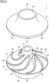
- a closed impeller (1) has a substantially circular truncated cone-shape.
- the closed impeller (1) has a center portion (11) having a smallest outer diameter and an outer circumferential portion (12) having a largest outer diameter.
- the closed impeller (1) has a through hole (13) at a rotation center thereof.
- the through hole (13) of the closed impeller (1) is for insertion of a shaft of a centrifugal compressor (not illustrated).
- the shaft of the centrifugal compressor is connected to a driving device such as a motor, and a driving force of the driving device is transmitted to the closed impeller (1) via the shaft.
- the closed impeller (1) rotates in this manner.
- the center portion (11) has an inlet (15).
- the inlet (15) opens in an axial direction of the closed impeller (1).
- the outer circumferential portion (12) has outlets (16).
- the outlets (16) are open outwardly in the radial direction of the closed impeller (1).
- the closed impeller (1) has an internal channel (17) formed inside of the closed impeller (1) and connecting the inlet (15) to the outlets (16).
- the inlet (15) of the closed impeller (1) is an opening surrounded by an upstream edge portion (25) of a hub portion (21), described later, blade portions (22), and a shroud (30).
- Each outlet (16) of the closed impeller (1) is an opening surrounded by a downstream edge portion (27) of the hub portion (21), described later, the blade portions (22), and the shroud (30).
- the internal channel (17) of the closed impeller (1) is a space surrounded by a curving portion (26) (see FIG. 2 ) of the hub portion (21), described later, the blade portions (22), and the shroud (30).
- the closed impeller (1) is rotated in a centrifugal compressor, thereby sucking a fluid through the inlet (15).
- the fluid thus sucked through the inlet (15) flows through the internal channel (17) and is guided to the outlets (16) while being accelerated due to the rotation of the closed impeller (1).
- the fluid discharged from the outlets (16) is compressed in a diffuser of the centrifugal compressor.
- the closed impeller (1) includes an impeller body (20) and the shroud (30).
- the shroud (30) covers the blade portions (22) of the impeller body (20).
- the impeller body (20) is made of an aluminum alloy.
- the impeller body (20) includes the hub portion (21) and a plurality of blade portions (22).
- the hub portion (21) and the blade portions (22) are formed as an integral part by machining of a block made of the aluminum alloy.
- the hub portion (21) has a substantially circular truncated cone-shape.
- the hub portion (21) has the upstream edge portion (25), the downstream edge portion (27), and the curving portion (26).
- the upstream edge portion (25) is the edge portion where the inlet (15) is formed.
- the downstream edge portion (27) is the edge portion where the outlets (16) are formed.
- the curving portion (26) connects the upstream edge portion (25) and the downstream edge portion (27).
- the curving portion (26) is curved such that a contour of the curving portion (26) in a cross section including the rotation center of the closed impeller (1) is recessed inwardly.
- the circumferential dimension of the curving portion (26) increases gradually from the upstream edge portion (25) to the downstream edge portion (27).
- the hub portion (21) has the through hole (13) penetrating the hub portion (21) in the axial direction.
- the through hole (13) is open at a center portion of the upstream edge portion (25) and a center portion of the downstream edge portion (27).
- the impeller body (20) includes the plurality of blade portions (22).
- the blade portions (22) project from the curving portion (26) toward the shroud (30).
- the blade portions (22) are helically arranged in plan view as viewed from the inlet (15).
- the blade portions (22) extend from the upstream edge portion (25) to the downstream edge portion (27) of the hub portion (21).
- Each of the blade portions (22) has an end portion that is curved along an end portion of a protrusion (33) of the shroud (30) described later.
- the shroud (30) is made of a brazing sheet.
- the shroud (30) includes a core material (31) and a brazing material (32) layered on a one-sided surface of the core material (31) (see FIG. 5 ).
- the shroud (30) is formed into a funnel-like shape by press forming the brazing sheet.
- the shroud (30) is placed so as to cover the end portions of the blade portions (22).
- the shroud (30) has a center opening (35) at its center.
- the upstream edge portion (25) of the hub portion (21) is arranged in the center opening (35) (see FIG. 1 ).
- the shroud (30) has the plurality of protrusions (33).
- the plurality of protrusions (33) extend helically along the blade portions (22) of the impeller body (20).
- the protrusions (33) has end portions where the brazing material (32) is provided.
- the shroud (30) has no brazing material (32) on a surface facing the impeller body (20), except on the protrusions (33).
- the shroud (30) is formed into a funnel-like shape by press forming a brazing sheet having the brazing material (32) on the one-sided surface.
- the brazing material (32) is provided all over the inner surface of the shroud (30).
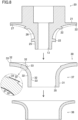
- the inner surface of the shroud (30) is partially removed by cutting with a ball end mill (80), so that the plurality of protrusions (33) protrude relatively.
- the brazing material (32) remains on the end portions of the protrusions (33), whereas the brazing material (32) on the other portions is removed.
- the shroud (30) and the impeller body (20) are joined together by thermally melting the brazing material (32), with the protrusions (33) of the shroud (30) and the blade portions (22) of the impeller body (20) fitted together.
- the brazing sheet forming the shroud (30) includes the brazing material (32) having a thickness of about 100 ⁇ m to about 150 ⁇ m.
- the brazing material (32) at the portions not used for the joining the impeller body (20) and the shroud (30) may be totally removed from the portions, or the brazing material (32) in the vicinities of the protrusions (33), which are joint portions, may be left by cutting about 20 ⁇ m to about 80 ⁇ m with the ball end mill (80).
- the closed impeller (1) may be produced by the following method, for example.
- the impeller body (20) and the shroud (30) are prepared separately.
- the shroud (30) is formed by press forming the brazing sheet including the core material (31) and the brazing material (32).
- the brazing sheet includes the core material (31) made of an aluminum alloy containing Mg by 0.20 mass% or more and less than 1.80 mass%, and the brazing material (32) made of an Al-Si based alloy and having a thickness of from 100 ⁇ m to 150 ⁇ m.
- the press forming may be performed so that the brazing material (32) of the brazing sheet be positioned on the inner side of the closed impeller (1), i.e., on the side facing the blade portions (22).
- the plurality of protrusions (33) is formed on the surface of the shroud (30) facing impeller body (20). Specifically, as illustrated in FIG. 5 , the inner surface of the shroud (30) is partially removed by cutting with a ball end mill (80), so that the plurality of protrusions (33) protrude relatively.
- the brazing material (32) remains on the end portions of the protrusions (33), whereas the brazing material (32) on the other portions is removed.
- the impeller body (20) is obtainable by, for example, machining a block of the aluminum alloy and forming the hub portion (21) and the blade portions (22) as an integral part.
- the end portions of the blade portions (22) of the impeller body (20) are machined into a shape corresponding to the shape of the end portions of the protrusions (33) in the shroud (30).
- the shape of the end portions of the blade portions (22) of the impeller body (20) is formed using data obtained in advance through measurement of the shape of the press-formed shroud (30) by a 3D coordinate measuring machine or the like.
- the shroud (30) may be set on a processing machine and data obtained through measurement of the shape of the shroud (30) may be used in machining the impeller body (20).
- the shroud (30) may be machined as appropriate such that the thickness of the brazing material (32) of the shroud (30) is reduced to the extent that there still remains the brazing material (32), thereby reducing a gap between the shroud (30) and the end portions of the blade portions (22) of the impeller body (20).
- about 20 ⁇ m to about 80 ⁇ m of the brazing material (32) may be cut off because the brazing material (32) has a thickness of about 100 ⁇ m to about 150 ⁇ m.
- the brazing material (32) has a thickness that is greater in an outer circumferential portion of the shroud (30) than in a center portion of the shroud (30).
- the thickness of the brazing material (32) is 100 ⁇ m in the outer circumferential portion of the shroud (30) and 50 ⁇ m in the center portion of the shroud (30).
- the shroud (30) thus prepared is held with the center portion of the shroud (30) facing downward. Then, the blade portions (22) of the impeller body (20) are fitted on the protrusions (33) of the shroud (30). Here, the end portions of the blade portions (22) of the impeller body (20) are brought into contact with the brazing material (32) on the end portions of the protrusions (33) of the shroud (30).
- the impeller body (20) and the shroud (30) are heated in an inert gas so as to melt the brazing material (32), thereby brazing the impeller body (20) and the shroud (30).
- the blade portions (22) of the impeller body (20) and the shroud (30) are joined together via the brazing material (32).
- the closing impeller (1) is produced in this manner.
- the use of the shroud (30) formed from the brazing sheet makes it possible to perform the brazing without using a binder or flux, which has been employed in known dip brazing.
- the plurality of protrusions (33) is provided on a surface of the press-formed shroud (30) facing the impeller body (20).
- the protrusions (33) extend along the blade portions (22) and are joined to the corresponding blade portions (22) via the brazing material (32).
- This configuration enables brazing between the press-formed shroud (30) and the impeller body (20) fitted together, with a small assembly gap therebetween. Moreover, the thickness of the brazing material (32) after the brazing is thin, thereby increasing joining strength.
- the shroud (30) has no brazing material (32) on the surface facing the impeller body (20), except the end portions of the protrusions (33).
- brazing material (32) is removed in advance from the portions not used for the joining the impeller body (20) and the shroud (30), dripping of the brazing material (32) can be reduced.
- the shape of the end portions of the blade portions (22) corresponds to the shape of the end portions of the protrusions (33). This configuration enables brazing with a small gap between the blade portions (22) and the protrusions (33).
- the impeller body (20) is machined, and the shroud (30) is press formed.
- a surface of the shroud (30) facing the impeller body (20) is partially removed by cutting to form a plurality of protrusions (33).
- the protrusions (33) and the blade portions (22) are brazed while fitted together.
- This configuration enables brazing between the press-formed shroud (30) and the impeller body (20) fitted together, with a small assembly gap therebetween.
- the brazing material (32) has a thickness that is greater in the outer circumferential portion of the shroud (30) than in the center portion of the shroud (30). In the brazing, the shroud (30) is held with its center portion facing downward.
- brazing it is possible to ensure enough amount of the brazing material (32) between the protrusions (33) and the blade portions (22) in the outer circumferential portion, and increase the joining strength, even if a portion of the brazing material (32) liquefied in the outer circumferential portion of the shroud (30) flows toward the center portion.
- the closed impeller (1) includes an impeller body (20) and a shroud (30).
- the impeller body (20) includes the hub portion (21) and a plurality of blade portions (22).
- the shroud (30) has a first member (37) and a second member (38).
- the first member (37) includes a core material (31) and a brazing material (32) provided on both surfaces of the core material (31).
- the first member (37) is press formed.
- the first member (37) is placed to cover end portions of the blade portions (22).
- a plurality of protrusions (33) are provided on a surface of the first member (37) facing the impeller body (20).
- the plurality of protrusions (33) extend helically along the blade portions (22) of the impeller body (20).
- the protrusions (33) has end portions where the brazing material (32) is provided.
- the second member (38) is formed into a funnel-like shape by press forming.
- the second member (38) has a hole at its center portion, and the hole has a diameter substantially equal to the outer diameter of a center portion of the first member (37).
- the second member (38) is placed on a surface of the first member (37) opposite to the surface facing the impeller body (20).
- the shroud (30) is held with the center portions of the first member (37) and the second member (38) facing downward. Then, the blade portions (22) of the impeller body (20) are fitted on the protrusions (33) of the shroud (30). Here, the end portions of the blade portions (22) of the impeller body (20) are brought into contact with the brazing material (32) on the end portions of the protrusions (33) of the shroud (30).
- the impeller body (20), the first member (37), and the second member (38) are heated in an inert gas so as to melt the brazing material (32), thereby brazing the impeller body (20) and the shroud (30).
- the blade portions (22) of the impeller body (20) and the first member (37) of the shroud (30) are joined to each other via the brazing material (32) provided on the protrusions (33).
- the first member (37) and the second member (38) are joined to each other via the brazing material (32) provided on the outer surface of the first member (37).
- a part of the second member (38) is removed by cutting with a ball end mill (80) after the impeller body (20) and the shroud (30) are brazed together.
- the thickness of the shroud (30) is restricted to a press-formable thickness.
- a situation may occur where the outer diameter of the center portion of the shroud (30) does not agree with a dimension of a part (e.g., a seal ring) to be attached to the shroud (30).
- the second member (38) is brazed to the first member (37) to increase the thickness, and a part of the second member (38) is removed by cutting, thereby adjusting the outer diameter of the closed impeller (1) to a desired dimension.
- the closing impeller (1) is produced in this manner.
- the shroud (30) includes the first member (37) and the second member (38).
- the first member (37) is joined to the impeller body (20).
- the second member (38) is joined to the first member (37) on the opposite side to the side where the impeller body (20) is joined.
- the first member (37) includes the brazing material (32) on each of the surface for joining to the impeller body (20) and the surface for joining to the second member (38).
- brazing material (32) is provided on both surfaces of the first member (37), it is possible to braze the impeller body (20) and the second member (38) to the first member (37).
- the second member (38) is brazed to the surface of the first member (37) opposite to the surface facing the impeller body (20). After the brazing, the second member (38) is partially removed by cutting.
- the brazing material (32) between the first member (37) and the portions of the second member (38) to be removed by cutting can flow to the portions where joining is necessary. This can increase the joining strength.
- the shroud (30) having the brazing material (32) on a one-sided surface is formed by press forming a brazing sheet and is brazed to the impeller body (20), but is not limited thereto.
- the shroud (30) may be formed by press forming a core material (31) made of an aluminum alloy, and the shroud (30) and the impeller body (20) may be brazed to each other via a brazing material pasted therebetween.
- the protrusions (33) of the shroud (30) may be machined more than they are designed in the axial direction. Specifically, in brazing the impeller body (20) and the shroud (30), the brazing material (32) on the protrusions (33) of the shroud (30) melts, which may cause a relative movement of the shroud (30) in the axial direction and narrow the gap between the shroud (30) and the impeller body (20). As a result, the channel area of the internal channel (17) may be reduced.
- the brazing material (32) may include a plurality of layers having different colors so that the state of removal in machining the shroud (30) can be easily determined.
- the core material (31) of the shroud (30) may include a plurality of layers having different colors.
- the present disclosure is useful as a closed impeller and a method for producing a closed impeller.
Landscapes
- Engineering & Computer Science (AREA)
- Mechanical Engineering (AREA)
- General Engineering & Computer Science (AREA)
- Structures Of Non-Positive Displacement Pumps (AREA)
Applications Claiming Priority (2)
| Application Number | Priority Date | Filing Date | Title |
|---|---|---|---|
| JP2020082754A JP6982267B2 (ja) | 2020-05-08 | 2020-05-08 | クローズドインペラ及びクローズドインペラの製造方法 |
| PCT/JP2021/007762 WO2021225024A1 (ja) | 2020-05-08 | 2021-03-01 | クローズドインペラ及びクローズドインペラの製造方法 |
Publications (3)
| Publication Number | Publication Date |
|---|---|
| EP4134553A1 true EP4134553A1 (de) | 2023-02-15 |
| EP4134553A4 EP4134553A4 (de) | 2024-05-01 |
| EP4134553B1 EP4134553B1 (de) | 2025-12-31 |
Family
ID=78409368
Family Applications (1)
| Application Number | Title | Priority Date | Filing Date |
|---|---|---|---|
| EP21800861.3A Active EP4134553B1 (de) | 2020-05-08 | 2021-03-01 | Geschlossenes laufrad und verfahren zur herstellung eines geschlossenen laufrads |
Country Status (5)
| Country | Link |
|---|---|
| US (1) | US11879476B2 (de) |
| EP (1) | EP4134553B1 (de) |
| JP (1) | JP6982267B2 (de) |
| CN (1) | CN115485479B (de) |
| WO (1) | WO2021225024A1 (de) |
Families Citing this family (7)
| Publication number | Priority date | Publication date | Assignee | Title |
|---|---|---|---|---|
| US11473592B2 (en) * | 2019-08-13 | 2022-10-18 | Emerson Climate Technologies, Inc. | Systems and methods for manufacturing a shrouded impeller |
| US12370615B2 (en) * | 2021-03-05 | 2025-07-29 | Danfoss A/S | Techniques for applying brazing material to form a shrouded impeller |
| CN116006506A (zh) * | 2022-12-28 | 2023-04-25 | 珠海格力电器股份有限公司 | 叶轮及风机 |
| DE102023116229B4 (de) * | 2023-06-21 | 2026-02-26 | Ebm-Papst Mulfingen Gmbh & Co. Kg | Laufrad für Radiallüfter |
| CN117206828A (zh) * | 2023-08-23 | 2023-12-12 | 中科航星科技有限公司西安分公司 | 一种提高闭式离心叶轮真空钎焊成型强度的方法 |
| CN117128187B (zh) * | 2023-10-17 | 2024-05-24 | 上海交通大学 | 一种应用闭式叶轮的离心压缩机扩稳增效的端壁处理方法 |
| JP2025162324A (ja) * | 2024-04-15 | 2025-10-27 | 川崎重工業株式会社 | クローズドインペラの製造方法 |
Family Cites Families (22)
| Publication number | Priority date | Publication date | Assignee | Title |
|---|---|---|---|---|
| DE1059610B (de) * | 1953-09-19 | 1959-06-18 | Maschf Augsburg Nuernberg Ag | Aus Einzelteilen durch Schmelzverbindung hergestelltes Laufrad fuer Stroemungsmaschinen |
| JPS4890008A (de) * | 1972-03-04 | 1973-11-24 | ||
| JPS5173607A (ja) * | 1974-12-24 | 1976-06-25 | Mitsui Shipbuilding Eng | Enshinatsushukukinohaneguruma |
| JPS54145005A (en) * | 1978-05-04 | 1979-11-12 | Hitachi Ltd | Manufacturing method of pump runner |
| JPS6272696U (de) * | 1985-10-28 | 1987-05-09 | ||
| JP3291827B2 (ja) * | 1993-03-18 | 2002-06-17 | 株式会社日立製作所 | 羽根車及びディフューザ、並びにその製作方法 |
| JP2000145690A (ja) * | 1998-11-09 | 2000-05-26 | Hitachi Ltd | 電動送風機及びそれを備えた電気掃除機 |
| US6419450B1 (en) * | 2001-05-21 | 2002-07-16 | Grundfos Pumps Manufacturing Corporation | Variable width pump impeller |
| JP2003328989A (ja) * | 2002-05-16 | 2003-11-19 | Hitachi Industries Co Ltd | 羽根車の製作方法 |
| JP2010121612A (ja) * | 2008-10-23 | 2010-06-03 | Mitsubishi Heavy Ind Ltd | インペラ、圧縮機およびインペラの製造方法 |
| WO2010090062A1 (ja) * | 2009-02-06 | 2010-08-12 | 三菱重工業株式会社 | インペラ、圧縮機およびインペラの製造方法 |
| JP4699531B2 (ja) | 2009-01-27 | 2011-06-15 | 三菱重工業株式会社 | インペラの製造方法およびインペラ |
| JP2010180721A (ja) * | 2009-02-03 | 2010-08-19 | Mitsubishi Heavy Ind Ltd | インペラの製造方法および圧縮機 |
| IT1394295B1 (it) * | 2009-05-08 | 2012-06-06 | Nuovo Pignone Spa | Girante centrifuga del tipo chiuso per turbomacchine, componente per tale girante, turbomacchina provvista di tale girante e metodo di realizzazione di tale girante |
| CN102817869A (zh) * | 2012-08-13 | 2012-12-12 | 势加透博(北京)科技有限公司 | 大型离心压缩机叶轮及其加工成形方法 |
| KR101909708B1 (ko) * | 2013-07-22 | 2018-10-18 | 한화파워시스템 주식회사 | 유체 회전 기계의 일체형 임펠러 조립체 및 일체형 임펠러 조립체의 제조 방법 |
| KR102126866B1 (ko) * | 2013-08-07 | 2020-06-25 | 한화파워시스템 주식회사 | 유체 회전 기계의 임펠러 조립체 및 임펠러 조립체의 제조 방법 |
| JP6202731B2 (ja) * | 2013-08-29 | 2017-09-27 | 三菱重工業株式会社 | インペラの組立方法 |
| JP5920422B2 (ja) * | 2014-08-25 | 2016-05-18 | 株式会社ノーリツ | 羽根車、羽根車の製造方法および給湯装置 |
| JP5920378B2 (ja) * | 2014-02-24 | 2016-05-18 | 株式会社ノーリツ | ファンおよびそれを備える給湯装置 |
| WO2018148789A1 (en) * | 2017-02-14 | 2018-08-23 | Resmed Limited | An impeller for a respiratory device |
| US11473592B2 (en) * | 2019-08-13 | 2022-10-18 | Emerson Climate Technologies, Inc. | Systems and methods for manufacturing a shrouded impeller |
-
2020
- 2020-05-08 JP JP2020082754A patent/JP6982267B2/ja active Active
-
2021
- 2021-03-01 WO PCT/JP2021/007762 patent/WO2021225024A1/ja not_active Ceased
- 2021-03-01 CN CN202180032783.XA patent/CN115485479B/zh active Active
- 2021-03-01 EP EP21800861.3A patent/EP4134553B1/de active Active
-
2022
- 2022-11-04 US US17/981,062 patent/US11879476B2/en active Active
Also Published As
| Publication number | Publication date |
|---|---|
| EP4134553B1 (de) | 2025-12-31 |
| CN115485479B (zh) | 2023-10-24 |
| US11879476B2 (en) | 2024-01-23 |
| JP6982267B2 (ja) | 2021-12-17 |
| US20230058821A1 (en) | 2023-02-23 |
| WO2021225024A1 (ja) | 2021-11-11 |
| CN115485479A (zh) | 2022-12-16 |
| EP4134553A4 (de) | 2024-05-01 |
| JP2021177075A (ja) | 2021-11-11 |
Similar Documents
| Publication | Publication Date | Title |
|---|---|---|
| EP4134553A1 (de) | Geschlossenes laufrad und verfahren zur herstellung eines geschlossenen laufrads | |
| CN103097739B (zh) | 叶轮、具备该叶轮的旋转机械以及叶轮的制造方法 | |
| CN104903561B (zh) | 涡轮转子及装入有该涡轮转子的涡轮增压机 | |
| EP2093380B1 (de) | Einkanaliger Innenring mit leichtem Innenkern in einer Gasturbine | |
| EP2216119B1 (de) | Herstellungsverfahren für Laufrad | |
| EP1971782B1 (de) | Laufrad | |
| US20110318183A1 (en) | Method for Producing a Shrouded Impeller from Two or More Components | |
| CN102625881B (zh) | 叶轮的制造方法 | |
| EP2727681A1 (de) | Herstellungsverfahren einer leichter gemachten Turbomaschinenschaufel | |
| WO2011132509A1 (ja) | 過給機用のコンプレッサハウジング及びその製造方法 | |
| EP2213881A2 (de) | Verdichterrad und Verfahren zu ihrer Herstellung | |
| EP2123916A2 (de) | Verdichtergehäuse | |
| US9664055B2 (en) | Impeller and rotary machine provided with the same | |
| CA2448465A1 (en) | Fabricated repair of cast nozzle | |
| CA2598260A1 (en) | Repairable labyrinth seal | |
| EP3059454B1 (de) | Laufrad, rotationsmaschine und laufradherstellungsverfahren | |
| KR20150145185A (ko) | 압축기 및 압축기의 제조 방법 | |
| EP1424465A1 (de) | Hybridrotor; verfahren zur herstellung eines hybridrotors; und gasturbine | |
| US20090067996A1 (en) | Blade bearing ring assembly of a turbocharger with a variable turbine geometry | |
| KR102488574B1 (ko) | 임펠러 및 이의 제조방법 | |
| JPH08303389A (ja) | 遠心羽根車及び該遠心羽根車の製造方法 | |
| US20260125985A1 (en) | Turbine and manufacturing method of turbine | |
| JP3464753B2 (ja) | 組立て一体型翼車及びその製造方法 | |
| WO2025079293A1 (ja) | タービン、および、タービンの製造方法 | |
| JP2006038043A (ja) | トルクコンバータ |
Legal Events
| Date | Code | Title | Description |
|---|---|---|---|
| STAA | Information on the status of an ep patent application or granted ep patent |
Free format text: STATUS: THE INTERNATIONAL PUBLICATION HAS BEEN MADE |
|
| PUAI | Public reference made under article 153(3) epc to a published international application that has entered the european phase |
Free format text: ORIGINAL CODE: 0009012 |
|
| STAA | Information on the status of an ep patent application or granted ep patent |
Free format text: STATUS: REQUEST FOR EXAMINATION WAS MADE |
|
| 17P | Request for examination filed |
Effective date: 20221108 |
|
| AK | Designated contracting states |
Kind code of ref document: A1 Designated state(s): AL AT BE BG CH CY CZ DE DK EE ES FI FR GB GR HR HU IE IS IT LI LT LU LV MC MK MT NL NO PL PT RO RS SE SI SK SM TR |
|
| P01 | Opt-out of the competence of the unified patent court (upc) registered |
Effective date: 20230525 |
|
| DAV | Request for validation of the european patent (deleted) | ||
| DAX | Request for extension of the european patent (deleted) | ||
| A4 | Supplementary search report drawn up and despatched |
Effective date: 20240402 |
|
| RIC1 | Information provided on ipc code assigned before grant |
Ipc: F04D 29/22 20060101ALN20240325BHEP Ipc: F04D 29/62 20060101ALI20240325BHEP Ipc: F04D 29/02 20060101ALI20240325BHEP Ipc: F04D 29/28 20060101AFI20240325BHEP |
|
| STAA | Information on the status of an ep patent application or granted ep patent |
Free format text: STATUS: EXAMINATION IS IN PROGRESS |
|
| 17Q | First examination report despatched |
Effective date: 20241206 |
|
| GRAP | Despatch of communication of intention to grant a patent |
Free format text: ORIGINAL CODE: EPIDOSNIGR1 |
|
| STAA | Information on the status of an ep patent application or granted ep patent |
Free format text: STATUS: GRANT OF PATENT IS INTENDED |
|
| RIC1 | Information provided on ipc code assigned before grant |
Ipc: F04D 29/28 20060101AFI20250814BHEP Ipc: F04D 29/02 20060101ALI20250814BHEP Ipc: F04D 29/62 20060101ALI20250814BHEP Ipc: F04D 29/22 20060101ALN20250814BHEP |
|
| INTG | Intention to grant announced |
Effective date: 20250903 |
|
| GRAS | Grant fee paid |
Free format text: ORIGINAL CODE: EPIDOSNIGR3 |
|
| GRAA | (expected) grant |
Free format text: ORIGINAL CODE: 0009210 |
|
| STAA | Information on the status of an ep patent application or granted ep patent |
Free format text: STATUS: THE PATENT HAS BEEN GRANTED |
|
| AK | Designated contracting states |
Kind code of ref document: B1 Designated state(s): AL AT BE BG CH CY CZ DE DK EE ES FI FR GB GR HR HU IE IS IT LI LT LU LV MC MK MT NL NO PL PT RO RS SE SI SK SM TR |
|
| REG | Reference to a national code |
Ref country code: CH Ref legal event code: F10 Free format text: ST27 STATUS EVENT CODE: U-0-0-F10-F00 (AS PROVIDED BY THE NATIONAL OFFICE) Effective date: 20251231 Ref country code: GB Ref legal event code: FG4D |
|
| REG | Reference to a national code |
Ref country code: DE Ref legal event code: R096 Ref document number: 602021045545 Country of ref document: DE |
|
| REG | Reference to a national code |
Ref country code: IE Ref legal event code: FG4D |
|
| PGFP | Annual fee paid to national office [announced via postgrant information from national office to epo] |
Ref country code: GB Payment date: 20260324 Year of fee payment: 6 |
|
| REG | Reference to a national code |
Ref country code: LT Ref legal event code: MG9D |
|
| PG25 | Lapsed in a contracting state [announced via postgrant information from national office to epo] |
Ref country code: NO Free format text: LAPSE BECAUSE OF FAILURE TO SUBMIT A TRANSLATION OF THE DESCRIPTION OR TO PAY THE FEE WITHIN THE PRESCRIBED TIME-LIMIT Effective date: 20260331 |
|
| PGFP | Annual fee paid to national office [announced via postgrant information from national office to epo] |
Ref country code: DE Payment date: 20260319 Year of fee payment: 6 |
|
| PG25 | Lapsed in a contracting state [announced via postgrant information from national office to epo] |
Ref country code: HR Free format text: LAPSE BECAUSE OF FAILURE TO SUBMIT A TRANSLATION OF THE DESCRIPTION OR TO PAY THE FEE WITHIN THE PRESCRIBED TIME-LIMIT Effective date: 20251231 Ref country code: FI Free format text: LAPSE BECAUSE OF FAILURE TO SUBMIT A TRANSLATION OF THE DESCRIPTION OR TO PAY THE FEE WITHIN THE PRESCRIBED TIME-LIMIT Effective date: 20251231 |
|
| PG25 | Lapsed in a contracting state [announced via postgrant information from national office to epo] |
Ref country code: RS Free format text: LAPSE BECAUSE OF FAILURE TO SUBMIT A TRANSLATION OF THE DESCRIPTION OR TO PAY THE FEE WITHIN THE PRESCRIBED TIME-LIMIT Effective date: 20260331 |
|
| PGFP | Annual fee paid to national office [announced via postgrant information from national office to epo] |
Ref country code: FR Payment date: 20260323 Year of fee payment: 6 |
|
| PG25 | Lapsed in a contracting state [announced via postgrant information from national office to epo] |
Ref country code: LV Free format text: LAPSE BECAUSE OF FAILURE TO SUBMIT A TRANSLATION OF THE DESCRIPTION OR TO PAY THE FEE WITHIN THE PRESCRIBED TIME-LIMIT Effective date: 20251231 |