EP4134556A1 - Ensemble de fixation - Google Patents
Ensemble de fixation Download PDFInfo
- Publication number
- EP4134556A1 EP4134556A1 EP22158234.9A EP22158234A EP4134556A1 EP 4134556 A1 EP4134556 A1 EP 4134556A1 EP 22158234 A EP22158234 A EP 22158234A EP 4134556 A1 EP4134556 A1 EP 4134556A1
- Authority
- EP
- European Patent Office
- Prior art keywords
- vertical beam
- movable part
- turnover
- transmission rod
- fastening assembly
- Prior art date
- Legal status (The legal status is an assumption and is not a legal conclusion. Google has not performed a legal analysis and makes no representation as to the accuracy of the status listed.)
- Granted
Links
Images


Classifications
-
- F—MECHANICAL ENGINEERING; LIGHTING; HEATING; WEAPONS; BLASTING
- F16—ENGINEERING ELEMENTS AND UNITS; GENERAL MEASURES FOR PRODUCING AND MAINTAINING EFFECTIVE FUNCTIONING OF MACHINES OR INSTALLATIONS; THERMAL INSULATION IN GENERAL
- F16B—DEVICES FOR FASTENING OR SECURING CONSTRUCTIONAL ELEMENTS OR MACHINE PARTS TOGETHER, e.g. NAILS, BOLTS, CIRCLIPS, CLAMPS, CLIPS OR WEDGES; JOINTS OR JOINTING
- F16B13/00—Dowels or other devices fastened in walls or the like by inserting them in holes made therein for that purpose
- F16B13/04—Dowels or other devices fastened in walls or the like by inserting them in holes made therein for that purpose with parts gripping in the hole or behind the reverse side of the wall after inserting from the front
- F16B13/08—Dowels or other devices fastened in walls or the like by inserting them in holes made therein for that purpose with parts gripping in the hole or behind the reverse side of the wall after inserting from the front with separate or non-separate gripping parts moved into their final position in relation to the body of the device without further manual operation
- F16B13/0808—Dowels or other devices fastened in walls or the like by inserting them in holes made therein for that purpose with parts gripping in the hole or behind the reverse side of the wall after inserting from the front with separate or non-separate gripping parts moved into their final position in relation to the body of the device without further manual operation by a toggle-mechanism
-
- F—MECHANICAL ENGINEERING; LIGHTING; HEATING; WEAPONS; BLASTING
- F16—ENGINEERING ELEMENTS AND UNITS; GENERAL MEASURES FOR PRODUCING AND MAINTAINING EFFECTIVE FUNCTIONING OF MACHINES OR INSTALLATIONS; THERMAL INSULATION IN GENERAL
- F16B—DEVICES FOR FASTENING OR SECURING CONSTRUCTIONAL ELEMENTS OR MACHINE PARTS TOGETHER, e.g. NAILS, BOLTS, CIRCLIPS, CLAMPS, CLIPS OR WEDGES; JOINTS OR JOINTING
- F16B13/00—Dowels or other devices fastened in walls or the like by inserting them in holes made therein for that purpose
- F16B13/12—Separate metal or non-separate or non-metal dowel sleeves fastened by inserting the screw, nail or the like
- F16B13/124—Separate metal or non-separate or non-metal dowel sleeves fastened by inserting the screw, nail or the like fastened by inserting a threaded element, e.g. screw or bolt
-
- F—MECHANICAL ENGINEERING; LIGHTING; HEATING; WEAPONS; BLASTING
- F16—ENGINEERING ELEMENTS AND UNITS; GENERAL MEASURES FOR PRODUCING AND MAINTAINING EFFECTIVE FUNCTIONING OF MACHINES OR INSTALLATIONS; THERMAL INSULATION IN GENERAL
- F16B—DEVICES FOR FASTENING OR SECURING CONSTRUCTIONAL ELEMENTS OR MACHINE PARTS TOGETHER, e.g. NAILS, BOLTS, CIRCLIPS, CLAMPS, CLIPS OR WEDGES; JOINTS OR JOINTING
- F16B13/00—Dowels or other devices fastened in walls or the like by inserting them in holes made therein for that purpose
- F16B13/001—Dowels or other devices fastened in walls or the like by inserting them in holes made therein for that purpose with means for preventing rotation of the dowel
-
- F—MECHANICAL ENGINEERING; LIGHTING; HEATING; WEAPONS; BLASTING
- F16—ENGINEERING ELEMENTS AND UNITS; GENERAL MEASURES FOR PRODUCING AND MAINTAINING EFFECTIVE FUNCTIONING OF MACHINES OR INSTALLATIONS; THERMAL INSULATION IN GENERAL
- F16B—DEVICES FOR FASTENING OR SECURING CONSTRUCTIONAL ELEMENTS OR MACHINE PARTS TOGETHER, e.g. NAILS, BOLTS, CIRCLIPS, CLAMPS, CLIPS OR WEDGES; JOINTS OR JOINTING
- F16B13/00—Dowels or other devices fastened in walls or the like by inserting them in holes made therein for that purpose
- F16B13/002—Dowels or other devices fastened in walls or the like by inserting them in holes made therein for that purpose self-cutting
-
- F—MECHANICAL ENGINEERING; LIGHTING; HEATING; WEAPONS; BLASTING
- F16—ENGINEERING ELEMENTS AND UNITS; GENERAL MEASURES FOR PRODUCING AND MAINTAINING EFFECTIVE FUNCTIONING OF MACHINES OR INSTALLATIONS; THERMAL INSULATION IN GENERAL
- F16B—DEVICES FOR FASTENING OR SECURING CONSTRUCTIONAL ELEMENTS OR MACHINE PARTS TOGETHER, e.g. NAILS, BOLTS, CIRCLIPS, CLAMPS, CLIPS OR WEDGES; JOINTS OR JOINTING
- F16B5/00—Joining sheets or plates, e.g. panels, to one another or to strips or bars parallel to them
- F16B5/06—Joining sheets or plates, e.g. panels, to one another or to strips or bars parallel to them by means of clamps or clips
- F16B5/0607—Joining sheets or plates, e.g. panels, to one another or to strips or bars parallel to them by means of clamps or clips joining sheets or plates to each other
- F16B5/0621—Joining sheets or plates, e.g. panels, to one another or to strips or bars parallel to them by means of clamps or clips joining sheets or plates to each other in parallel relationship
- F16B5/0642—Joining sheets or plates, e.g. panels, to one another or to strips or bars parallel to them by means of clamps or clips joining sheets or plates to each other in parallel relationship the plates being arranged one on top of the other and in full close contact with each other
-
- F—MECHANICAL ENGINEERING; LIGHTING; HEATING; WEAPONS; BLASTING
- F16—ENGINEERING ELEMENTS AND UNITS; GENERAL MEASURES FOR PRODUCING AND MAINTAINING EFFECTIVE FUNCTIONING OF MACHINES OR INSTALLATIONS; THERMAL INSULATION IN GENERAL
- F16B—DEVICES FOR FASTENING OR SECURING CONSTRUCTIONAL ELEMENTS OR MACHINE PARTS TOGETHER, e.g. NAILS, BOLTS, CIRCLIPS, CLAMPS, CLIPS OR WEDGES; JOINTS OR JOINTING
- F16B13/00—Dowels or other devices fastened in walls or the like by inserting them in holes made therein for that purpose
- F16B13/04—Dowels or other devices fastened in walls or the like by inserting them in holes made therein for that purpose with parts gripping in the hole or behind the reverse side of the wall after inserting from the front
- F16B13/06—Dowels or other devices fastened in walls or the like by inserting them in holes made therein for that purpose with parts gripping in the hole or behind the reverse side of the wall after inserting from the front combined with expanding sleeve
- F16B13/061—Dowels or other devices fastened in walls or the like by inserting them in holes made therein for that purpose with parts gripping in the hole or behind the reverse side of the wall after inserting from the front combined with expanding sleeve of the buckling type
-
- F—MECHANICAL ENGINEERING; LIGHTING; HEATING; WEAPONS; BLASTING
- F16—ENGINEERING ELEMENTS AND UNITS; GENERAL MEASURES FOR PRODUCING AND MAINTAINING EFFECTIVE FUNCTIONING OF MACHINES OR INSTALLATIONS; THERMAL INSULATION IN GENERAL
- F16B—DEVICES FOR FASTENING OR SECURING CONSTRUCTIONAL ELEMENTS OR MACHINE PARTS TOGETHER, e.g. NAILS, BOLTS, CIRCLIPS, CLAMPS, CLIPS OR WEDGES; JOINTS OR JOINTING
- F16B37/00—Nuts or like thread-engaging members
- F16B37/04—Devices for fastening nuts to surfaces, e.g. sheets, plates
- F16B37/041—Releasable devices
- F16B37/043—Releasable devices with snap action
Definitions
- the disclosure relates to the technical field of connection, in particular to a fastening assembly.
- connection of two objects is usually realized by bolts and nuts.
- the bolts are threaded through the mounting holes of the two objects, and the user correspondingly sets the nuts on the bolts to complete the connection of the two objects.
- artificially aligning the set nuts will increase the labor intensity and affect the use experience of users.
- the disclosure aims to solve at least one of the technical problems existing in the prior art, and the disclosure provides a fastening assembly, which can reduce the labor intensity of users and optimize the use experience of users.
- a fastening assembly including a mounting cylinder frame, a movable part, and a turnover part.
- the mounting cylinder frame is provided with a first vertical beam and a transmission rod
- the mounting cylinder frame is provided with a butting block at a top of the first vertical beam
- the transmission rod passes through the butting block
- a side wall of the first vertical beam is provided with a bulge.
- the movable part is connected with the transmission rod.
- the turnover part is arranged on the first vertical beam and is rotatably connected with the movable part, the turnover part is butted with the bulge, the turnover part is located between the butting block and the movable part, and the turnover part has a vertical state and a horizontal state, wherein, the transmission rod is configured to drive the movable part to move along an axial direction of the first vertical beam, so as to drive the turnover part to switch between the horizontal state or the vertical state under an action of the bulge.
- the turnover part can be switched from the vertical state to the horizontal state only through the transmission rod, wherein the turnover part in the horizontal state and the butting block together clamp the two objects, so as to complete the connection of the two objects.
- the above connection does not require the user to manually align the set nut. Therefore, the labor intensity of the user can be reduced to optimize the use experience.
- the movable part includes the movable part body and a connecting block.
- the movable part body is slidably connected with the first vertical beam, the movable part body is rotationally connected with the turnover part, and the movable part body is provided with a mounting cavity.
- the connecting block is embedded in the mounting cavity, and the connecting block is sleeved on the transmission rod and threaded with the transmission rod.
- the movable part body is provided with a connecting shaft
- the turnover part is provided with a guide slot
- the connecting shaft passes through the guide slot
- the connecting block partially extends out of the mounting cavity, and the turnover part is provided with a snap notch matched with the extending portion of the connecting block; and the extending portion of the connecting block is embedded in the snap notch when the turnover part is in a horizontal state.
- the movable part body is provided with an anti-falling block, and the anti-falling block is butted with the connecting block.
- the mounting cylinder frame is provided with a second vertical beam, the second vertical beam, the first vertical beam and the transmission rod are arranged side by side, and the second vertical beam is slidably connected with the movable part body.
- the first vertical beam is provided with a platform, and the turnover part in the vertical state is butted with the platform.
- the first vertical beam is provided with an avoidance hole, and the avoidance hole is arranged corresponding to the bulge.
- the first vertical beam is provided with a positioning block, the positioning block butts against a top of the movable part (200) when the turnover part (300) is in a vertical state.
- the turnover part is provided with anti-skid teeth; and the anti-skid teeth are facing the butting block when the turnover part is in a horizontal state.
- orientation or position relationship related to the orientation description is based on the orientation or position relationship shown in the attached drawings, only for the convenience of describing the disclosure and simplifying the description, rather than indicating or implying that the device or element must have a specific orientation, or being constructed and operated in a specific orientation. Therefore, it cannot be understood as a limitation of the present disclosure.
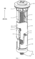
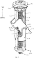
- an embodiment of the present disclosure relates to a fastening assembly, including a mounting cylinder frame 100, a movable part 200 and a turnover part 300.
- the mounting cylinder frame 100 is provided with a first vertical beam 111 and a transmission rod 121 which are arranged side by side.
- the mounting cylinder frame 100 is provided with a butting block 112 at the top of the first vertical beam 111, the transmission rod 121 passes through the butting block 112, and the side wall of the first vertical beam 111 is provided with a bulge 111A.
- the movable part 200 is connected with the transmission rod 121.
- the turnover part 300 is rotationally connected with the movable part 200.
- the turnover part 300 is butted with the bulge 111A, the turnover part 300 is located between the butting block 112 and the movable part 200, and the turnover part 300 has a vertical state and a horizontal state.
- the transmission rod 121 can drive the movable part 200 to move along the axial direction of the first vertical beam 111 to come close or move away from the butting block 112, so as to drive the turnover part 300 to turnover under the force of the bulge 111A, so as to switch between the horizontal state or the vertical state.
- the top projection of the turnover part 300 is in a U shape.
- the turnover part 300 includes a connecting arm 310 and two opposite turnover arms 320. Both ends of the connecting arm 310 are respectively connected with the two turnover arms 320. Both sides of the first vertical beam 111 are provided with bulges 111A, and the two bulges 111A are butted with the inner walls of the two turnover arms 320 one by one.
- the turnover arm 320 is rotatably connected with the movable part 200, wherein the connecting arm 310 and the two turnover arms 320 are an integrated structure.
- the transmission rod 121 can drive the movable part 200 to move in the direction close to the butting block 112.
- the movable part 200 moving close to the butting block 112 pushes the rotating arm 320 to overturn, so that the turnover arm 320 switches to the horizontal state under the friction force of the bulge 111A.
- the turnover arm 320 switches to the horizontal state, the turnover arm 320 butts with the movable part 200, the turnover arm 320 remains horizontal, and the movable part 200 can continue to push the turnover arm 320 in the horizontal state so that the turnover arm 320 continues to move in the direction close to the butting block 112.
- the transmission rod 121 can drive the movable part 200 to move away from the butting block 112, and the movable part 200 moving away from the butting block 112 pulls the turnover arm 320 to move, so that the turnover arm 320 is turnover to the vertical state under the friction force of the bulge 111A.
- the two bulges 111A are butted with the inner walls of the two turnover arms 320 one by one, which shows that the turnover part 300 is arranged on the first vertical beam 111.
- the turnover part 300 can be switched from the vertical state to the horizontal state only through the transmission rod 121.
- the turnover part 300 in the horizontal state and the butting block 112 together clamp the two objects to complete the connection of the two objects.
- the above connection does not require the user to manually align the set nut. Therefore, it can reduce the labor intensity of users and optimize the user experience.
- fastening assembly can also connect three, four or more objects.
- the horizontal length of the turnover part 300 in the horizontal state is greater than the aperture of the mounting hole.
- the turnover arm 320 is provided with anti-skid teeth 323.
- the anti-skid teeth 323 are facing the butting block 112.
- the anti-skid teeth 323 and the butting block 112 together clamp the two objects, so as to increase the clamping effect of the two objects and optimize the connection stability of the two objects.
- the first vertical beam 111 is provided with an avoidance section
- the avoidance section is provided with an avoidance hole 111C
- the side wall of the avoidance section is provided with a bulge 111A.
- the arrangement of the avoidance hole 111C can make the two bulges 111A suitable for coping with the force when the turnover part 300 moves and overturn, so as to avoid the damage of the two bulges 111A due to too rigid.
- the first vertical beam 111 is provided with a positioning block 111D.
- the positioning block 111D butts against the top of the movable part 200.
- the mounting cylinder frame 100 includes a cylinder frame body 100 and a bolt 120.
- the cylinder frame body 100 is provided with the first vertical beam 111 and the butting block 112, the bolt 120 is threaded through the cylinder frame body 110, the head of the bolt 120 is located above the butting block 112, and the rod portion of the bolt 120 is the transmission rod 121.
- the mounting cylinder frame 100 includes a cylinder frame body 100 and a push rod member, the cylinder frame body 100 is provided with the first vertical beam 111 and the butting block 112, the push rod member is arranged on the mounting cylinder frame 100, and the rod part of the push rod member is the transmission rod 121.
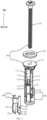
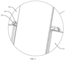
- the bolt 120 In order to reduce the friction between the bolt 120 and the cylinder frame body 110, referring to FIG. 1 and FIG. 2 , it also includes a gasket 400.
- the gasket 400 is sleeved on the transmission rod 121, and the gasket 400 is located between the butting block 112 and the head of the bolt 120.
- the first vertical beam 111 is provided with a platform 111B, and the connecting arm 310 of the turnover part 300 in the vertical state is butted with the platform 111B.
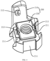
- the movable part 200 includes a movable part body 210 and a connecting block 220.
- the movable part body 210 is slidably connected with the first vertical beam 111, the movable part body 210 is rotationally connected with the turnover arm 320, the movable part body 210 is provided with a mounting cavity, the connecting block 220 is embedded in the mounting cavity, and the connecting block 220 is sleeved on the transmission rod 121 and threaded with the transmission rod 121.
- the connecting block 220 is provided with a polygonal nut, and the mounting cavity is matched with the connecting block 220.
- the bottom of the mounting cavity is provided with an avoidance hole for the transmission rod 121 to pass through.
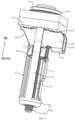
- the movable part body 210 is slidably connected with the first vertical beam 111. Specifically, referring to FIG. 2 , FIG. 3 and FIG. 4 , the movable part body 210 is provided with a first sliding slot 211, and the first vertical beam 111 is slidably arranged in the first sliding slot 211.
- the cylinder frame body 110 is further provided with a second vertical beam 113, the second vertical beam 113, the first vertical beam 111 and the transmission rod 121 are arranged side by side.
- the movable part body 210 is provided with a second sliding slot 214 corresponding to the second vertical beam 113, and the second vertical beam 113 is slidably arranged in the second sliding slot 214.
- a limit space is formed between the first vertical beam 111 and part of the second vertical beam 113, wherein one turnover arm 320 is located in the limit space.
- the number of the second vertical beam 113 and the second sliding slot 214 is set to two.
- the number of the second vertical beam 113 and the second sliding slot 214 is set to three, four, etc.
- the movable part body 210 is rotationally connected with the turnover arm 320. Specifically, referring to FIGS. 3 to 4 , the movable part body 210 is provided with a connecting shaft 212, the turnover arm 320 is provided with a guide slot 321, and the connecting shaft 212 passes through the guide slot 321.
- the connecting shaft 212 slides in the guide slot 321 and rotates relative to the turnover arm 320.
- the movable part body 210 is provided with an anti-falling block 213, wherein the anti-falling block 213 is butted against the connecting block 220.
- the connecting block 220 partially extends out of the mounting cavity, and the turnover arm 320 is provided with a snap notch 322 matched with the extending portion of the connecting block 220.
- the turnover arm 320 is in a horizontal state, the extending portion of the connecting block 220 is embedded in the snap notch 322.
- the extending portion of the connecting block 220 is embedded in the snap notch 322 to increase the stability of butting between the turnover part 300 and the movable part 200, and can be further limited to the connecting block 220 in the mounting cavity.
Landscapes
- Engineering & Computer Science (AREA)
- General Engineering & Computer Science (AREA)
- Mechanical Engineering (AREA)
- Mutual Connection Of Rods And Tubes (AREA)
- Polarising Elements (AREA)
- Non-Silver Salt Photosensitive Materials And Non-Silver Salt Photography (AREA)
- Massaging Devices (AREA)
Applications Claiming Priority (1)
| Application Number | Priority Date | Filing Date | Title |
|---|---|---|---|
| CN202121876730.XU CN216044797U (zh) | 2021-08-11 | 2021-08-11 | 一种紧固组件 |
Publications (3)
| Publication Number | Publication Date |
|---|---|
| EP4134556A1 true EP4134556A1 (fr) | 2023-02-15 |
| EP4134556B1 EP4134556B1 (fr) | 2023-07-05 |
| EP4134556C0 EP4134556C0 (fr) | 2023-07-05 |
Family
ID=80558129
Family Applications (1)
| Application Number | Title | Priority Date | Filing Date |
|---|---|---|---|
| EP22158234.9A Active EP4134556B1 (fr) | 2021-08-11 | 2022-02-23 | Ensemble de fixation |
Country Status (4)
| Country | Link |
|---|---|
| US (1) | US12031562B2 (fr) |
| EP (1) | EP4134556B1 (fr) |
| CN (1) | CN216044797U (fr) |
| ES (1) | ES2952322T3 (fr) |
Families Citing this family (3)
| Publication number | Priority date | Publication date | Assignee | Title |
|---|---|---|---|---|
| CN113623296B (zh) * | 2021-08-11 | 2024-12-10 | 中山市美图塑料工业有限公司 | 一种紧固组件 |
| US12049911B2 (en) * | 2021-08-18 | 2024-07-30 | Delta Cycle Corporation | Anchor assembly |
| USD1088851S1 (en) * | 2023-10-18 | 2025-08-19 | Junrui Cai | Bolt |
Citations (5)
| Publication number | Priority date | Publication date | Assignee | Title |
|---|---|---|---|---|
| FR1385043A (fr) * | 1963-02-26 | 1965-01-08 | Dispositif de fixation | |
| US3532024A (en) * | 1968-12-26 | 1970-10-06 | Tool Works Inc | Toggle fastener |
| US4502826A (en) * | 1983-05-16 | 1985-03-05 | Centre De Recherche Industrielle Du Quebec | Toggle fastener |
| CA2592203A1 (fr) * | 2006-06-21 | 2007-12-21 | John D. Davis | Dispositif pre-positionnable d'ancrage a barrette articulee |
| US20090169331A1 (en) * | 2007-12-31 | 2009-07-02 | Jean Pilon | Wall anchor |
Family Cites Families (11)
| Publication number | Priority date | Publication date | Assignee | Title |
|---|---|---|---|---|
| US1386202A (en) * | 1918-07-24 | 1921-08-02 | U S Expansion Bolt Co | Attaching device |
| US2024871A (en) * | 1935-06-13 | 1935-12-17 | Edwin R Parsons | Toggle bolt and sleeve |
| US2950141A (en) * | 1957-05-28 | 1960-08-23 | Bell Telephone Labor Inc | Panel latch |
| US3127807A (en) * | 1961-10-13 | 1964-04-07 | Henry J Modrey | Hollow wall anchor with pivoted anchor member |
| DK105081C (da) * | 1964-02-24 | 1966-08-15 | Aackersberg Mortensen | Fastgørelsesorgan. |
| US4530630A (en) * | 1982-07-14 | 1985-07-23 | Brown Russell L | Expanding anchor fastener |
| JP4472167B2 (ja) * | 2000-12-12 | 2010-06-02 | 若井産業株式会社 | 回転ナット |
| US6764261B1 (en) * | 2001-11-13 | 2004-07-20 | David Stadler | Locking device and method for catch basin and manhole covers, and the like |
| US6884012B2 (en) * | 2003-09-04 | 2005-04-26 | Illinois Tool Works Inc. | Heavy duty toggle bolt fastener assembly, and method of installing and removing the same |
| US11486432B2 (en) * | 2018-11-29 | 2022-11-01 | The Hillman Group, Inc. | Anchor assembly with toggle |
| EP4012198B1 (fr) * | 2020-12-08 | 2025-04-23 | Xiamen Beewill Sanitary Co., Ltd. | Ensemble de verrouillage |
-
2021
- 2021-08-11 CN CN202121876730.XU patent/CN216044797U/zh active Active
-
2022
- 2022-02-23 EP EP22158234.9A patent/EP4134556B1/fr active Active
- 2022-02-23 ES ES22158234T patent/ES2952322T3/es active Active
- 2022-02-23 US US17/678,989 patent/US12031562B2/en active Active
Patent Citations (5)
| Publication number | Priority date | Publication date | Assignee | Title |
|---|---|---|---|---|
| FR1385043A (fr) * | 1963-02-26 | 1965-01-08 | Dispositif de fixation | |
| US3532024A (en) * | 1968-12-26 | 1970-10-06 | Tool Works Inc | Toggle fastener |
| US4502826A (en) * | 1983-05-16 | 1985-03-05 | Centre De Recherche Industrielle Du Quebec | Toggle fastener |
| CA2592203A1 (fr) * | 2006-06-21 | 2007-12-21 | John D. Davis | Dispositif pre-positionnable d'ancrage a barrette articulee |
| US20090169331A1 (en) * | 2007-12-31 | 2009-07-02 | Jean Pilon | Wall anchor |
Also Published As
| Publication number | Publication date |
|---|---|
| EP4134556B1 (fr) | 2023-07-05 |
| US20230047591A1 (en) | 2023-02-16 |
| EP4134556C0 (fr) | 2023-07-05 |
| ES2952322T3 (es) | 2023-10-30 |
| CN216044797U (zh) | 2022-03-15 |
| US12031562B2 (en) | 2024-07-09 |
Similar Documents
| Publication | Publication Date | Title |
|---|---|---|
| EP4134556A1 (fr) | Ensemble de fixation | |
| TW200905098A (en) | Pivot structure of universal joint | |
| EP3398481A1 (fr) | Ensemble de rails de glissement | |
| US20200180146A1 (en) | Assembly for driving waist of robot and robot having the same | |
| CN112498673B (zh) | 驱动机构和无人机 | |
| JP2019034111A (ja) | スライドレールアセンブリ及びそのレールキット | |
| CN113623296B (zh) | 一种紧固组件 | |
| CN215479350U (zh) | 一种伸缩臂及工程机械 | |
| US5762303A (en) | Tilting angle adjusting device for use in a projector | |
| JP2002194784A (ja) | スライド式シャワーフック取付装置 | |
| CN210577739U (zh) | 一种便于安装的电源智能保护器 | |
| CN212129113U (zh) | 塑料排水板倒带装置 | |
| JP2947088B2 (ja) | 射出成形機 | |
| CN210858465U (zh) | 一种铝合金门窗转角结构 | |
| US20220355614A1 (en) | Folding Wheel and Portable Appliance | |
| JP2001106128A (ja) | 建設機械の下部走行体 | |
| CN224068961U (zh) | 显示设备 | |
| JP2018003402A (ja) | 可動間仕切壁 | |
| WO2014061720A1 (fr) | Meuble ayant un rabat de dessus de table | |
| US11808255B2 (en) | Floor pump | |
| JP2020082338A (ja) | 多機能トルクレンチ | |
| CN110454659A (zh) | 一种监控装置 | |
| CN220815491U (zh) | 一种顶棚帘 | |
| CN216374084U (zh) | 一种轮胎便携拆装设备 | |
| JP2755016B2 (ja) | 引出形遮断器 |
Legal Events
| Date | Code | Title | Description |
|---|---|---|---|
| PUAI | Public reference made under article 153(3) epc to a published international application that has entered the european phase |
Free format text: ORIGINAL CODE: 0009012 |
|
| STAA | Information on the status of an ep patent application or granted ep patent |
Free format text: STATUS: REQUEST FOR EXAMINATION WAS MADE |
|
| 17P | Request for examination filed |
Effective date: 20220223 |
|
| AK | Designated contracting states |
Kind code of ref document: A1 Designated state(s): AL AT BE BG CH CY CZ DE DK EE ES FI FR GB GR HR HU IE IS IT LI LT LU LV MC MK MT NL NO PL PT RO RS SE SI SK SM TR |
|
| GRAP | Despatch of communication of intention to grant a patent |
Free format text: ORIGINAL CODE: EPIDOSNIGR1 |
|
| STAA | Information on the status of an ep patent application or granted ep patent |
Free format text: STATUS: GRANT OF PATENT IS INTENDED |
|
| INTG | Intention to grant announced |
Effective date: 20230310 |
|
| GRAS | Grant fee paid |
Free format text: ORIGINAL CODE: EPIDOSNIGR3 |
|
| GRAA | (expected) grant |
Free format text: ORIGINAL CODE: 0009210 |
|
| STAA | Information on the status of an ep patent application or granted ep patent |
Free format text: STATUS: THE PATENT HAS BEEN GRANTED |
|
| AK | Designated contracting states |
Kind code of ref document: B1 Designated state(s): AL AT BE BG CH CY CZ DE DK EE ES FI FR GB GR HR HU IE IS IT LI LT LU LV MC MK MT NL NO PL PT RO RS SE SI SK SM TR |
|
| REG | Reference to a national code |
Ref country code: CH Ref legal event code: EP |
|
| REG | Reference to a national code |
Ref country code: AT Ref legal event code: REF Ref document number: 1585096 Country of ref document: AT Kind code of ref document: T Effective date: 20230715 |
|
| REG | Reference to a national code |
Ref country code: DE Ref legal event code: R096 Ref document number: 602022000166 Country of ref document: DE |
|
| REG | Reference to a national code |
Ref country code: IE Ref legal event code: FG4D |
|
| U01 | Request for unitary effect filed |
Effective date: 20230717 |
|
| U07 | Unitary effect registered |
Designated state(s): AT BE BG DE DK EE FI FR IT LT LU LV MT NL PT SE SI Effective date: 20230725 |
|
| REG | Reference to a national code |
Ref country code: LT Ref legal event code: MG9D |
|
| REG | Reference to a national code |
Ref country code: ES Ref legal event code: FG2A Ref document number: 2952322 Country of ref document: ES Kind code of ref document: T3 Effective date: 20231030 |
|
| PG25 | Lapsed in a contracting state [announced via postgrant information from national office to epo] |
Ref country code: GR Free format text: LAPSE BECAUSE OF FAILURE TO SUBMIT A TRANSLATION OF THE DESCRIPTION OR TO PAY THE FEE WITHIN THE PRESCRIBED TIME-LIMIT Effective date: 20231006 |
|
| PG25 | Lapsed in a contracting state [announced via postgrant information from national office to epo] |
Ref country code: IS Free format text: LAPSE BECAUSE OF FAILURE TO SUBMIT A TRANSLATION OF THE DESCRIPTION OR TO PAY THE FEE WITHIN THE PRESCRIBED TIME-LIMIT Effective date: 20231105 |
|
| PG25 | Lapsed in a contracting state [announced via postgrant information from national office to epo] |
Ref country code: RS Free format text: LAPSE BECAUSE OF FAILURE TO SUBMIT A TRANSLATION OF THE DESCRIPTION OR TO PAY THE FEE WITHIN THE PRESCRIBED TIME-LIMIT Effective date: 20230705 Ref country code: NO Free format text: LAPSE BECAUSE OF FAILURE TO SUBMIT A TRANSLATION OF THE DESCRIPTION OR TO PAY THE FEE WITHIN THE PRESCRIBED TIME-LIMIT Effective date: 20231005 Ref country code: IS Free format text: LAPSE BECAUSE OF FAILURE TO SUBMIT A TRANSLATION OF THE DESCRIPTION OR TO PAY THE FEE WITHIN THE PRESCRIBED TIME-LIMIT Effective date: 20231105 Ref country code: HR Free format text: LAPSE BECAUSE OF FAILURE TO SUBMIT A TRANSLATION OF THE DESCRIPTION OR TO PAY THE FEE WITHIN THE PRESCRIBED TIME-LIMIT Effective date: 20230705 Ref country code: GR Free format text: LAPSE BECAUSE OF FAILURE TO SUBMIT A TRANSLATION OF THE DESCRIPTION OR TO PAY THE FEE WITHIN THE PRESCRIBED TIME-LIMIT Effective date: 20231006 |
|
| U20 | Renewal fee for the european patent with unitary effect paid |
Year of fee payment: 3 Effective date: 20240108 |
|
| PG25 | Lapsed in a contracting state [announced via postgrant information from national office to epo] |
Ref country code: PL Free format text: LAPSE BECAUSE OF FAILURE TO SUBMIT A TRANSLATION OF THE DESCRIPTION OR TO PAY THE FEE WITHIN THE PRESCRIBED TIME-LIMIT Effective date: 20230705 |
|
| REG | Reference to a national code |
Ref country code: DE Ref legal event code: R097 Ref document number: 602022000166 Country of ref document: DE |
|
| PG25 | Lapsed in a contracting state [announced via postgrant information from national office to epo] |
Ref country code: SM Free format text: LAPSE BECAUSE OF FAILURE TO SUBMIT A TRANSLATION OF THE DESCRIPTION OR TO PAY THE FEE WITHIN THE PRESCRIBED TIME-LIMIT Effective date: 20230705 Ref country code: RO Free format text: LAPSE BECAUSE OF FAILURE TO SUBMIT A TRANSLATION OF THE DESCRIPTION OR TO PAY THE FEE WITHIN THE PRESCRIBED TIME-LIMIT Effective date: 20230705 Ref country code: CZ Free format text: LAPSE BECAUSE OF FAILURE TO SUBMIT A TRANSLATION OF THE DESCRIPTION OR TO PAY THE FEE WITHIN THE PRESCRIBED TIME-LIMIT Effective date: 20230705 Ref country code: SK Free format text: LAPSE BECAUSE OF FAILURE TO SUBMIT A TRANSLATION OF THE DESCRIPTION OR TO PAY THE FEE WITHIN THE PRESCRIBED TIME-LIMIT Effective date: 20230705 |
|
| PLBE | No opposition filed within time limit |
Free format text: ORIGINAL CODE: 0009261 |
|
| STAA | Information on the status of an ep patent application or granted ep patent |
Free format text: STATUS: NO OPPOSITION FILED WITHIN TIME LIMIT |
|
| 26N | No opposition filed |
Effective date: 20240408 |
|
| PG25 | Lapsed in a contracting state [announced via postgrant information from national office to epo] |
Ref country code: MC Free format text: LAPSE BECAUSE OF FAILURE TO SUBMIT A TRANSLATION OF THE DESCRIPTION OR TO PAY THE FEE WITHIN THE PRESCRIBED TIME-LIMIT Effective date: 20230705 |
|
| PG25 | Lapsed in a contracting state [announced via postgrant information from national office to epo] |
Ref country code: IE Free format text: LAPSE BECAUSE OF NON-PAYMENT OF DUE FEES Effective date: 20240223 |
|
| U20 | Renewal fee for the european patent with unitary effect paid |
Year of fee payment: 4 Effective date: 20241226 |
|
| PG25 | Lapsed in a contracting state [announced via postgrant information from national office to epo] |
Ref country code: IE Free format text: LAPSE BECAUSE OF NON-PAYMENT OF DUE FEES Effective date: 20240223 |
|
| PGFP | Annual fee paid to national office [announced via postgrant information from national office to epo] |
Ref country code: ES Payment date: 20250317 Year of fee payment: 4 |
|
| PG25 | Lapsed in a contracting state [announced via postgrant information from national office to epo] |
Ref country code: CY Free format text: LAPSE BECAUSE OF FAILURE TO SUBMIT A TRANSLATION OF THE DESCRIPTION OR TO PAY THE FEE WITHIN THE PRESCRIBED TIME-LIMIT; INVALID AB INITIO Effective date: 20220223 |
|
| REG | Reference to a national code |
Ref country code: CH Ref legal event code: PL |
|
| PG25 | Lapsed in a contracting state [announced via postgrant information from national office to epo] |
Ref country code: CH Free format text: LAPSE BECAUSE OF NON-PAYMENT OF DUE FEES Effective date: 20250228 |
|
| PG25 | Lapsed in a contracting state [announced via postgrant information from national office to epo] |
Ref country code: TR Free format text: LAPSE BECAUSE OF FAILURE TO SUBMIT A TRANSLATION OF THE DESCRIPTION OR TO PAY THE FEE WITHIN THE PRESCRIBED TIME-LIMIT Effective date: 20230705 |
|
| U20 | Renewal fee for the european patent with unitary effect paid |
Year of fee payment: 5 Effective date: 20260128 |