EP4134575A1 - Entraînement de soupape, agencement de soupape et procédé - Google Patents
Entraînement de soupape, agencement de soupape et procédé Download PDFInfo
- Publication number
- EP4134575A1 EP4134575A1 EP22185432.6A EP22185432A EP4134575A1 EP 4134575 A1 EP4134575 A1 EP 4134575A1 EP 22185432 A EP22185432 A EP 22185432A EP 4134575 A1 EP4134575 A1 EP 4134575A1
- Authority
- EP
- European Patent Office
- Prior art keywords
- drive
- valve
- contour
- housing
- drive element
- Prior art date
- Legal status (The legal status is an assumption and is not a legal conclusion. Google has not performed a legal analysis and makes no representation as to the accuracy of the status listed.)
- Granted
Links
Images



Classifications
-
- F—MECHANICAL ENGINEERING; LIGHTING; HEATING; WEAPONS; BLASTING
- F16—ENGINEERING ELEMENTS AND UNITS; GENERAL MEASURES FOR PRODUCING AND MAINTAINING EFFECTIVE FUNCTIONING OF MACHINES OR INSTALLATIONS; THERMAL INSULATION IN GENERAL
- F16K—VALVES; TAPS; COCKS; ACTUATING-FLOATS; DEVICES FOR VENTING OR AERATING
- F16K31/00—Actuating devices; Operating means; Releasing devices
- F16K31/12—Actuating devices; Operating means; Releasing devices actuated by fluid
- F16K31/122—Actuating devices; Operating means; Releasing devices actuated by fluid the fluid acting on a piston
- F16K31/1221—Actuating devices; Operating means; Releasing devices actuated by fluid the fluid acting on a piston one side of the piston being spring-loaded
-
- F—MECHANICAL ENGINEERING; LIGHTING; HEATING; WEAPONS; BLASTING
- F16—ENGINEERING ELEMENTS AND UNITS; GENERAL MEASURES FOR PRODUCING AND MAINTAINING EFFECTIVE FUNCTIONING OF MACHINES OR INSTALLATIONS; THERMAL INSULATION IN GENERAL
- F16K—VALVES; TAPS; COCKS; ACTUATING-FLOATS; DEVICES FOR VENTING OR AERATING
- F16K1/00—Lift valves or globe valves, i.e. cut-off apparatus with closure members having at least a component of their opening and closing motion perpendicular to the closing faces
- F16K1/12—Lift valves or globe valves, i.e. cut-off apparatus with closure members having at least a component of their opening and closing motion perpendicular to the closing faces with streamlined valve member around which the fluid flows when the valve is opened
-
- F—MECHANICAL ENGINEERING; LIGHTING; HEATING; WEAPONS; BLASTING
- F16—ENGINEERING ELEMENTS AND UNITS; GENERAL MEASURES FOR PRODUCING AND MAINTAINING EFFECTIVE FUNCTIONING OF MACHINES OR INSTALLATIONS; THERMAL INSULATION IN GENERAL
- F16K—VALVES; TAPS; COCKS; ACTUATING-FLOATS; DEVICES FOR VENTING OR AERATING
- F16K31/00—Actuating devices; Operating means; Releasing devices
- F16K31/12—Actuating devices; Operating means; Releasing devices actuated by fluid
- F16K31/122—Actuating devices; Operating means; Releasing devices actuated by fluid the fluid acting on a piston
- F16K31/1226—Actuating devices; Operating means; Releasing devices actuated by fluid the fluid acting on a piston the fluid circulating through the piston
-
- F—MECHANICAL ENGINEERING; LIGHTING; HEATING; WEAPONS; BLASTING
- F16—ENGINEERING ELEMENTS AND UNITS; GENERAL MEASURES FOR PRODUCING AND MAINTAINING EFFECTIVE FUNCTIONING OF MACHINES OR INSTALLATIONS; THERMAL INSULATION IN GENERAL
- F16K—VALVES; TAPS; COCKS; ACTUATING-FLOATS; DEVICES FOR VENTING OR AERATING
- F16K7/00—Diaphragm valves or cut-off apparatus, e.g. with a member deformed, but not moved bodily, to close the passage ; Pinch valves
- F16K7/12—Diaphragm valves or cut-off apparatus, e.g. with a member deformed, but not moved bodily, to close the passage ; Pinch valves with flat, dished, or bowl-shaped diaphragm
- F16K7/126—Diaphragm valves or cut-off apparatus, e.g. with a member deformed, but not moved bodily, to close the passage ; Pinch valves with flat, dished, or bowl-shaped diaphragm the seat being formed on a rib perpendicular to the fluid line
Definitions
- the invention relates to advances in the field of valve technology.
- a first aspect of the description relates to a valve drive comprising a drive housing and a drive element, in particular a pneumatic piston, which is movably mounted within the drive housing in an assembled state of the valve drive, at least a first contour of the drive element engages in at least a second contour fixed to the drive housing in such a way that axial gearing blocks rotation of the drive element about an actuating axis in at least one direction of rotation.
- a valve drive which enables an element to be driven, for example a valve rod for valves, to be assembled or disassembled in the assembled state on the drive element, without it being necessary to counteract an assembly or disassembly torque introduced into the drive element.
- the valve rod is quickly and easily connected to the drive element without the need for additional tools.
- An advantageous example is characterized in that the drive element can be moved in a translatory manner along the adjusting axis and in a rotating manner about the adjusting axis in an operating state that differs from the assembled state.
- An advantageous example is characterized in that a compression spring, which is supported on the drive housing, presses the drive element in the direction of the contour that is fixed relative to the drive housing.
- valve drive is in the assembled state without being driven or controlled separately, and the drive element can be connected to the valve rod in this assembled state.
- An advantageous example is characterized in that, in the assembled state, a valve rod and the drive element can be connected to one another via interlocking threads.
- An advantageous example is characterized in that an intermediate body can be connected to an interface arranged on the valve housing via interlocking threads.
- valve devices can be configured in a modular manner, which have a large number of identical parts in the form of the valve drive. Accordingly, there are cost and production advantages, since the valve drive can be produced in larger quantities.
- An advantageous example is characterized in that the at least one second contour fixed to the drive housing is arranged on a second section running in particular perpendicular to the actuating axis within the drive housing, and the at least one first contour on a first section of the drive element running in particular perpendicular to the actuating axis , which faces the second section of the drive housing.
- the contours can thus be moved towards one another by an axial movement from an operating position and can engage in one another by rotating the drive element in the assembly position.
- first section of the drive element or the second section of the drive housing comprises surfaces running perpendicularly to the actuating axis, which are located between two adjacent ones of the first contours or two adjacent ones of the second contours, and wherein the second contour or the first contour includes a respective distal surface that is perpendicular to the actuating axis.
- the surfaces arranged between the respective contours ensure that the impacting contours of the opposite section allow the drive element to rotate until it snaps into the assembly position.
- an advantageous example is characterized in that one of the contours, the first contour of the drive element or the second contour fixed to the drive housing, is designed as a latching depression and the other of the contours is designed as a raised latching lug.
- the toothing can also be arranged radially instead of an axial toothing, that is to say mesh in the axial direction.
- valve drive enables the assembly state through a form-fitting engagement of space-saving, resilient contours in the form of axial teeth that withstand high shearing loads.
- An advantageous example is characterized in that in the assembled state at least one, better more Contours are engaged, which are arranged symmetrically, 3 contours are advantageous.
- the assembly or disassembly moment is introduced better and evenly distributed due to the arrangement or the symmetrical distribution at the engagement points.
- a second aspect of the description relates to a valve arrangement comprising the valve drive according to the first aspect, the valve drive being connected to a valve.
- a third aspect of the description relates to a method for assembling the valve drive according to the first aspect on a valve, comprising: arranging a valve rod of the valve on the drive element of the valve drive in the assembled state; attaching an intermediate body of the valve to the drive housing of the valve drive; and arranging a valve body of the valve on the intermediate body.
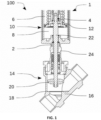
- the figure 1 shows a valve assembly 100 in a sectional view.
- the valve assembly 100 includes a valve drive 1, which includes an interface 2, a receiving device 4, the chambers 6 and 8, a drive housing housing 10 and a drive element 12, in particular a pneumatic piston.
- the receiving device 4 is arranged on the drive element 12 .
- the valve drive 1 is designed as a fluid-based drive, which is driven by the chambers 6 and 8 being filled and emptied. Appropriate design of the drive element 12 ensures that the chamber 8 facing away from the spring has a reduced volume of control air, which has the advantage of low compressed air consumption and thus increases efficiency.
- the outer area of the drive element 12 facing away from a spring is arranged offset from the inner connection area, pointing away from a spring, in order to reduce the volume of control air and to reach the latching position more easily.
- the piston 12 has a stepped design and includes a bearing point in the area of a closing element, which is identified below with the reference number 304 .
- the drive element 12 is moved within the drive housing 10.
- Other drive concepts such as electromagnetic drive technologies are of course also conceivable.
- the drive element 12 can also be designed differently than in figure 1 shown.
- the drive element 12 can also include a control diaphragm that is part of a diaphragm drive.
- the drive element 12 is mirrored in the area of the closing element on a perpendicular plane of an adjustment axis 310 .
- the gradation of the drive element 12 tapers in the direction of the valve body.
- the spring is supported on a section of the chamber 8 facing the valve body and pushes the drive element 12 away from the valve body.
- the valve arrangement 100 includes a seat valve 14 which includes a valve housing 16 , a valve seat 18 and a closing element 20 .
- a valve rod 22 arranged on the receiving device 4 creates a rigid connection between the valve drive 1 and the closing element 20 of the seat valve 14 .
- the valve housing 16 of the seat valve 14 is arranged at the interface 2 by means of an intermediate body 24 with the Valve drive 1 connected. Due to the rigid connection of the drive element 12 to the closing element 20 by means of the valve rod 22, the movement of the drive element 12 is transmitted to the closing element 20. As a result, the valve seat 18 is opened or closed and a flow through the valve housing 16 is controlled.
- the receiving device 4 and the interface 2 of the valve drive 1 can in particular be designed as a thread. Accordingly, the valve rod 22 and the intermediate body 24 also have a thread on the drive side.
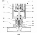
- the figure 2 shows another valve assembly 200 in a sectional view.
- the valve assembly 200 includes the valve drive 1 of figure 1 .
- the valve assembly 200 includes a membrane valve 26 which includes a valve body, an intermediate piece 28, a membrane 30 and a pressure piece 32.
- the membrane valve 26 is connected to the interface 2 of the valve drive 1 by means of the intermediate body 24 .
- the valve rod 22 forms a rigid connection between the drive element 12 and the membrane 30.
- valve rods of figures 1 and 2 are of identical design on the drive side in order to be attached to the receiving device 4 of the Drive element 12 to be arranged.
- the valve rods 22 differ only in a valve-side section. This valve-side section is designed to be arranged on a corresponding valve on a sealing element of the valve that is to be moved. For example, as in the figures 1 and 2 shown to be attached to the closing element 20 or to the membrane 30 can.
- the intermediate body 24 of figures 1 and 2 are identical at least on the drive side, so that the intermediate body 24 can be arranged at the interface 2 of the valve drive 1, and differ in a valve-side section.
- This valve-side section is designed to accommodate corresponding valves or valve bodies, such as the valve body 16 and the intermediate body 28 , and thus to connect them to the interface 2 of the valve drive 1 .
- valve rods 22 and intermediate bodies 24 of identical design on the drive side By using valve rods 22 and intermediate bodies 24 of identical design on the drive side, a large number of valve devices, such as the valve arrangement 100 and 200, can be constructed modularly with an identical or similarly designed drive, the valve drive 1 .
- the valve rod 22 and the intermediate body 24 are required, which are each adapted to the valve on the valve side.
- the large number of modularly constructed valve devices contains a large number of identical parts in the form of the uniform valve drive 1. Accordingly, there are cost and production advantages, since the valve drive 1 can be produced in larger quantities.
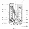
- the figure 3 shows the valve drive 1 in the assembled state as a sectional view.
- the valve drive 1 comprises the drive housing 10, which comprises a distal closing element 300, a wall 302 and a closing element 304 on the valve body side.
- the valve drive 1 comprises the drive element 12, which is mounted movably along an actuating axis 310 and is arranged between the closing elements 300 and 304, and a compression spring 308, which is arranged between the drive element 12 and the distal closing element 300.
- the closing elements 300 and 304, the wall 302 and the drive element 12 are designed in particular to be rotationally symmetrical.
- the axes of symmetry of these elements are arranged along the adjustment axis 310 .
- the drive element 12 In an operating state in which the valve drive 1 is operated with compressed air, the drive element 12 can be moved along the adjustment axis 310 in rotation and in translation relative to the fixed closing elements 300 and 304 and to the wall 302, i.e. to the drive housing 10. In the operating state, the drive element 12 can assume a plurality of operating positions.
- the compression spring 308 holds the drive element 12 in a possible extended position by a spring force if the valve drive 1 is not actuated accordingly. It is also conceivable that the compression spring 308 is arranged between the drive element 12 and the closing element 304 on the valve body side and holds the drive element 12 in a possible retracted position if the valve drive 1 is not actuated accordingly.
- the position of the valve drive 1 shown blocks a fixing device 312 the rotational degree of freedom of the drive element 12 about the actuating axis 310.
- This extended position is referred to as the assembly position.
- the fixing device 312 comprises first contours 314 arranged on a side of the drive element 12 facing towards the closing element 304 on the valve body side, in the present case designed as latching depressions.
- second contours 316 are fixed to the drive housing 10 and engage with the first contours 314 in a form-fitting manner in the assembly position.
- the compression spring 308 is designed to hold the drive element 12 in a position in which the valve body side of the piston can slide on surfaces which are arranged between the second contours 316 fixed to the drive housing 10 .
- the drive element 12 With this occurring rotation of the drive element 12 about the adjustment axis 310, for example during assembly or disassembly of a valve rod 22, the drive element 12 is moved into the assembly position.
- This has the effect that the first contours 314 are positively engaged with the second contours 316 fixed to the drive housing 10 and block the rotation of the drive element 12 about the adjustment axis 310 in both directions of rotation.
- the first contours 314 and the second contours 316 form the fixing device 312.
- the compression spring 308 is also designed to hold the drive element 12 in the assembly position it has reached. In addition, when the fixing device 312 engages, there is a tactile feedback to the user.
- the interlocking contours 314, 316 are designed in such a way that it is no longer possible to release the drive element via the latching mechanism, for example the contours 314, 316 are chamfered on one side for the latching mechanism.
- valve rod 22 of the valve to be driven can be easily and quickly connected to the valve drive 1 in the assembly position without the need for additional tools.
- the drive element 12 comprises a further receptacle 318 which is arranged in a region of the drive element 12 which faces the distal closing element 300 .
- the receptacle 318 is designed to accommodate, for example, an element of a signal transmitter that serves as a position indicator for the current position of the drive element 12 .
- the receptacle 318 is represented by a thread, for example.
- other connection techniques such as clip connections, bayonet locks, adhesive connections or material connections are also conceivable.
- the figure 4 shows the drive element 12 of the valve drive 1 in a perspective view.
- the drive element 12 includes a guide section 400 mounted in a sealing section 320 of the distal closing element and translationally along the actuating axis 310.
- the drive element 12 includes the first contour 314 in the form of latching depressions 314 a - f or an alternative contour, not shown, which forms part of the fixing device 312 of the valve drive 1 .
- fixation device 312 by two contours intermeshing outside of the chambers 6 and 8, for example by a first contour arranged on the guide section 400 of the drive element 12 and a second contour arranged on the distal closing element 302 in the area of the sealing section 320 or outside of the sealing section 320.
- the drive element 12 includes a sealing section 402 arranged on the circumference, which is in contact with the wall profile 302 and thereby separates the chambers 6 and 8 .
- the sealing section 402 in conjunction with the wall profile 302, also serves to mount the drive element 12.
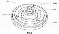
- the figure 5 shows the closing element 304 of the valve drive 1 on the valve body side in a perspective representation.
- the closing element 304 on the valve body side comprises the second contour 316 fixed to the drive housing 10 in the form of latching lugs 316 a - c, or alternative contours which depict part of the fixing device 312 of the valve drive 1 .
- the closing element 304 on the valve body side has an odd number of latching lugs 316 a - c. As a result, an assembly or disassembly moment is better initiated in the assembly position. Of course, an even number of latching lugs can also be provided.
- the closing element 304 on the valve body side also includes a passage opening 500 for the valve rod 22, for example for the coupling element for seat valves or Diaphragm valves 14 and 26. This passage opening 500 is also used for mounting the coupling element 22. As a result, the valve rod 22 is also mounted in addition to the receiving device 4. This results in a more stable construction of the valve arrangement 100 and 200, which has an increased service life and withstands higher loads.
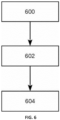
- FIG. 12 shows schematically a method for assembling the valve drive 1 on a valve 14 or 26 in order to obtain the valve arrangement 100 and 200.
- the valve rod 22 of the valve 14 and 26 is arranged on the drive element 12 of the valve drive 1 in a first step 600 by means of the receiving device 4 .
- the intermediate body 24 is attached to the interface 2 of the closing element 304 on the valve side.
- the valve body 16 or the intermediate body 28 of the valve 14 or 26 is arranged on the intermediate body 24 .
- the method steps 600, 602 and 604 can also be used for the assembly of a large number of valve arrangements with different valve types and valve sizes.
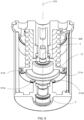
- FIGS 7 and 8th show an example of the drive 1 from the Figures 1 to 3 , with the drive member 12 in the operative position.
- the drive element 12 comprises the guide section 400 and a piston section 700 which is materially connected to the guide section 400.
- the guide section 400 and the piston section 700 are welded to one another.
- a resting position Drive element 12 is characterized in that the compression spring 308 has a maximum longitudinal extent when the drive 1 is in the mounted state. In the example shown, the rest position of the drive element 12 is oriented in the direction of the valve body (not shown) or in the direction of the interface 2 . The compression spring 308 therefore presses the drive element 12 in the direction of the interface 2.
- the guide section 400 is movably mounted to the drive housing 10 along the adjustment axis 310 .
- the piston section 700 connects radially outwards to the guide section 400 and provides the seal towards the cylinder inner surface.
- a counter bearing section 702 provides a contact surface for the compression spring 308 which is supported on the housing 10 .
- a cylindrical portion 704 of piston portion 700 extends parallel to actuator axis 310 and provides a radially outer surface to receive compression spring 308 .
- a first collar 706 of the piston section 700 protrudes from the cylindrical section 704 in the direction of the guide section 400 and is materially connected to it.
- a second collar 708 of piston portion 700 protrudes outward from cylindrical portion 704 .
- a first actuating fluid interface 710 carries fluid via a lateral channel 712 of the drive housing 10 a first chamber 716 connected.
- the channel 712 leads past a second chamber 714 in which the compression spring 308 is arranged.
- the chambers 714 and 716 are separated from one another in a pressure-tight manner by the drive element 12 .
- a second actuating fluid interface 718 is connected to the second chamber 714 in a fluid-carrying manner.
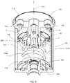
- FIG figures 9 and 10 show another example of the drive 1. Deviating from the example of FIG figures 7 and 8th is the rest position of the drive element 12 facing away from the valve body, not shown, or from the interface 2 .
- the compression spring 308 therefore presses the drive element 12 away from the interface 2 .
- the piston section 700 is rigidly, in particular materially connected, to the guide section 400 in a position mirrored in relation to a perpendicular of the actuating axis 310 .
- the guide section 400 and the piston section 700 are of the same design as in the example of FIG figures 7 and 8th .
- the effective contours for blocking the rotation of the drive element 12 are arranged at a different point.
- the figures 9 and 10 shown in an intermediate position of the drive element 12 along the adjustment axis 310 .
- the at least one first contour 314 arranged on the collar 706 of the piston section 700 engages Drive element 12 into the at least one second contour 316 fixed to the drive housing 10 in such a way that rotation of the drive element 12 about the actuating axis 310 is blocked in at least one direction of rotation.
- the fixed contours 316a, 316b are arranged at the distal end of a section 902 which extends cylindrically from the bottom of the interior space in the direction of the drive element 12.
- An annular groove 904 in the closure element 304 on the valve body side serves as a counter bearing for the compression spring 308, which is stationary relative to the drive housing 10.
- the drive element 12 is put together differently.
- the effective contours 314, 316 are arranged radially outside of the compression spring 308 or an imaginary cylindrical extension of the compression spring 308.
- the effective contours 316, 314 are arranged radially inside the compression spring 308.
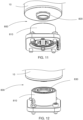
- the Figures 11 and 12 show a perspective view of an example of an interface 800 between the drive housing 10 and an intermediate body 810.
- the intermediate body 810 is arranged between the drive housing 10 and the valve body 16.
- the interface 800 comprises a coded section 820 on the drive body side and a coded mating section 830 on the intermediate body side.
- the section 820 and the mating section 830 can be fixed in several rotational positions relative to one another by the sections 820 and 830 engaging in a form-fitting manner, which, for example, offers advantages for the arrangement of laterally from the drive housing 10 wrangled connections result. This results in degrees of freedom during assembly.
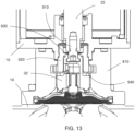
- FIG 13 shows a schematic longitudinal section of the drive housing 10, the intermediate body 810 and the valve body 16.
- An adapter 910 is introduced into the valve rod 22.
- a stroke limiter 920 extends from the interior of the intermediate body 810 into a recess in the drive housing 10.
- a stop region 930 of the stroke limiter 920 oriented in the direction of the drive body 10 limits a movement of the valve rod 22 in the direction of the valve body 16.
- a stop region 930 oriented in the direction of the valve body 16 Stop area 940 limits a movement of the pressure piece 32 in the direction of the drive body 10.
Landscapes
- Engineering & Computer Science (AREA)
- General Engineering & Computer Science (AREA)
- Mechanical Engineering (AREA)
- Physics & Mathematics (AREA)
- Fluid Mechanics (AREA)
- Fluid-Driven Valves (AREA)
- Valve Device For Special Equipments (AREA)
Priority Applications (1)
| Application Number | Priority Date | Filing Date | Title |
|---|---|---|---|
| EP24156655.3A EP4343191A3 (fr) | 2021-08-11 | 2022-07-18 | Agencement de soupape |
Applications Claiming Priority (1)
| Application Number | Priority Date | Filing Date | Title |
|---|---|---|---|
| DE102021120895.5A DE102021120895A1 (de) | 2021-08-11 | 2021-08-11 | Ventilantrieb, Ventilanordnung und Verfahren |
Related Child Applications (2)
| Application Number | Title | Priority Date | Filing Date |
|---|---|---|---|
| EP24156655.3A Division-Into EP4343191A3 (fr) | 2021-08-11 | 2022-07-18 | Agencement de soupape |
| EP24156655.3A Division EP4343191A3 (fr) | 2021-08-11 | 2022-07-18 | Agencement de soupape |
Publications (3)
| Publication Number | Publication Date |
|---|---|
| EP4134575A1 true EP4134575A1 (fr) | 2023-02-15 |
| EP4134575B1 EP4134575B1 (fr) | 2025-10-22 |
| EP4134575C0 EP4134575C0 (fr) | 2025-10-22 |
Family
ID=82655040
Family Applications (2)
| Application Number | Title | Priority Date | Filing Date |
|---|---|---|---|
| EP24156655.3A Pending EP4343191A3 (fr) | 2021-08-11 | 2022-07-18 | Agencement de soupape |
| EP22185432.6A Active EP4134575B1 (fr) | 2021-08-11 | 2022-07-18 | Entraînement de soupape, agencement de soupape et procédé |
Family Applications Before (1)
| Application Number | Title | Priority Date | Filing Date |
|---|---|---|---|
| EP24156655.3A Pending EP4343191A3 (fr) | 2021-08-11 | 2022-07-18 | Agencement de soupape |
Country Status (4)
| Country | Link |
|---|---|
| US (1) | US12338912B2 (fr) |
| EP (2) | EP4343191A3 (fr) |
| CN (1) | CN115704504A (fr) |
| DE (1) | DE102021120895A1 (fr) |
Citations (5)
| Publication number | Priority date | Publication date | Assignee | Title |
|---|---|---|---|---|
| DE202014102658U1 (de) * | 2014-06-06 | 2014-06-23 | Bürkert Werke GmbH | Membranventil |
| KR101424423B1 (ko) * | 2014-02-19 | 2014-08-01 | 아신하이밸주식회사 | 밸브 개폐용 유압식 로터리 액츄에이터 |
| EP2792918A1 (fr) * | 2013-04-18 | 2014-10-22 | Samson Aktiengesellschaft | Appareil de réglage pour une installation technologique |
| DE102018213712A1 (de) * | 2018-08-15 | 2020-02-20 | Festo Ag & Co. Kg | Ventilanordnung |
| JP2021046866A (ja) * | 2019-09-17 | 2021-03-25 | 株式会社コガネイ | 流量調整装置 |
Family Cites Families (21)
| Publication number | Priority date | Publication date | Assignee | Title |
|---|---|---|---|---|
| US3327992A (en) * | 1965-01-06 | 1967-06-27 | Sloan Valve Co | Control valves |
| US3310282A (en) * | 1965-11-15 | 1967-03-21 | Grinnell Corp | Diaphragm control valves |
| US3521674A (en) * | 1968-06-24 | 1970-07-28 | Beckman Instruments Inc | Sampling valve |
| US3874629A (en) * | 1971-11-23 | 1975-04-01 | Fail Safe Brake Corp | Fluid operated needle valve |
| JPS6051364U (ja) * | 1983-09-19 | 1985-04-11 | 旭有機材工業株式会社 | ゲ−トバルブ |
| US4834133A (en) * | 1988-09-28 | 1989-05-30 | Westinghouse Electric Corp. | Control valve |
| DE502007001900D1 (de) | 2006-09-20 | 2009-12-17 | Sauter Ag | Ventilantrieb |
| DE102007031957A1 (de) * | 2007-07-10 | 2009-01-22 | Pierburg Gmbh | Kombiniertes Rückschlag- und Steuerventil |
| DE102009023002B4 (de) | 2009-05-28 | 2012-02-09 | G.S. Anderson Gmbh | Membranventil-Antrieb |
| US8960224B2 (en) * | 2011-08-18 | 2015-02-24 | Cameron International Corporation | Valve position translator |
| US10132422B2 (en) | 2012-12-31 | 2018-11-20 | Ge Oil & Gas Pressure Control Lp | Compound express actuator connection |
| US9500294B2 (en) * | 2013-09-06 | 2016-11-22 | Ge Oil & Gas Pressure Control Lp | Hybrid manual and hydraulic actuator override |
| US9458947B2 (en) * | 2014-02-25 | 2016-10-04 | Fisher Controls International Lc | Actuator apparatus with internal tubing and anti-rotation mechanism |
| DE102014209186B4 (de) * | 2014-05-15 | 2026-04-23 | Robert Bosch Gmbh | Verfahren und Steuerung zum Betrieb eines Dosiermoduls |
| DE102015105489A1 (de) * | 2015-04-10 | 2016-10-13 | Bürkert Werke GmbH | Aktor |
| FR3042586B1 (fr) * | 2015-10-15 | 2018-03-09 | L'air Liquide, Societe Anonyme Pour L'etude Et L'exploitation Des Procedes Georges Claude | Bouteille de fluide sous pression |
| DE102016115638A1 (de) * | 2016-08-23 | 2018-03-01 | Gemü Gebr. Müller Apparatebau Gmbh & Co. Kommanditgesellschaft | Membranventil |
| DE102016123606A1 (de) | 2016-12-06 | 2018-06-07 | Gemü Gebr. Müller Apparatebau Gmbh & Co. Kommanditgesellschaft | Antriebsbaugruppe eines Membranventils und Verfahren zur Montage einer Antriebsbaugruppe |
| JP7015111B2 (ja) * | 2017-01-31 | 2022-02-08 | 株式会社キッツエスシーティー | バルブ用アクチュエータとこれを備えたダイヤフラムバルブ |
| US10337639B2 (en) * | 2017-08-16 | 2019-07-02 | Fisher Controls International Llc | Apparatus to bias a moveable tube towards a seal |
| DE102017123396A1 (de) * | 2017-10-09 | 2019-04-11 | Samson Aktiengesellschaft | Hubventil und Anordnung für ein Hubventil |
-
2021
- 2021-08-11 DE DE102021120895.5A patent/DE102021120895A1/de active Pending
-
2022
- 2022-07-18 EP EP24156655.3A patent/EP4343191A3/fr active Pending
- 2022-07-18 EP EP22185432.6A patent/EP4134575B1/fr active Active
- 2022-08-08 CN CN202210945654.6A patent/CN115704504A/zh active Pending
- 2022-08-08 US US17/882,955 patent/US12338912B2/en active Active
Patent Citations (5)
| Publication number | Priority date | Publication date | Assignee | Title |
|---|---|---|---|---|
| EP2792918A1 (fr) * | 2013-04-18 | 2014-10-22 | Samson Aktiengesellschaft | Appareil de réglage pour une installation technologique |
| KR101424423B1 (ko) * | 2014-02-19 | 2014-08-01 | 아신하이밸주식회사 | 밸브 개폐용 유압식 로터리 액츄에이터 |
| DE202014102658U1 (de) * | 2014-06-06 | 2014-06-23 | Bürkert Werke GmbH | Membranventil |
| DE102018213712A1 (de) * | 2018-08-15 | 2020-02-20 | Festo Ag & Co. Kg | Ventilanordnung |
| JP2021046866A (ja) * | 2019-09-17 | 2021-03-25 | 株式会社コガネイ | 流量調整装置 |
Also Published As
| Publication number | Publication date |
|---|---|
| EP4134575B1 (fr) | 2025-10-22 |
| CN115704504A (zh) | 2023-02-17 |
| US12338912B2 (en) | 2025-06-24 |
| DE102021120895A1 (de) | 2023-02-16 |
| EP4343191A3 (fr) | 2024-05-22 |
| EP4343191A2 (fr) | 2024-03-27 |
| EP4134575C0 (fr) | 2025-10-22 |
| US20230053312A1 (en) | 2023-02-16 |
| EP4343191A8 (fr) | 2024-05-08 |
Similar Documents
| Publication | Publication Date | Title |
|---|---|---|
| DE102007030006B4 (de) | Vakuumventil | |
| DE102006048573B4 (de) | Quetschventil | |
| DE102008061315B4 (de) | Aufhängung einer Ventilplatte an einer Ventilstange | |
| DE4101114C1 (fr) | ||
| DE102011015646A1 (de) | Fluidbetätigter Membranantrieb | |
| DE102007025974A1 (de) | Vakuumventil | |
| DE102016125134B3 (de) | Quetschventil | |
| DE102011100218A1 (de) | Ventil | |
| DE102016115638A1 (de) | Membranventil | |
| EP1423614A2 (fr) | Transmetteur de pression | |
| DE68917629T2 (de) | Ventil für Fluide. | |
| EP3425248A1 (fr) | Servomoteur pour soupapes de processus | |
| EP2113698A2 (fr) | Fil dentaire et emballage le contenant | |
| EP2728226B1 (fr) | Vanne à vide | |
| EP4134575B1 (fr) | Entraînement de soupape, agencement de soupape et procédé | |
| DE102007061188A1 (de) | Flanscheinrichtung | |
| DE102017109003A1 (de) | Zweidruckventil | |
| DE29711131U1 (de) | Mehrwegeventil | |
| WO2021073838A1 (fr) | Agencement avec une vanne | |
| DE69812907T2 (de) | Fluidbetätigtes ventil | |
| CH625023A5 (en) | Rotary drive arrangement for a fitting | |
| EP0141106A2 (fr) | Cylindre de travail à trois positions | |
| DE102022201230B4 (de) | Sicherheitsvorrichtung für ein linear betätigtes Prozessventil und System umfassend die Sicherheitsvorrichtung | |
| CH662869A5 (de) | Mehrwegventil. | |
| DE10153336A1 (de) | Druckmittelzylinder mit einer Einrichtung zur Verstellung des Kolbenhubs |
Legal Events
| Date | Code | Title | Description |
|---|---|---|---|
| PUAI | Public reference made under article 153(3) epc to a published international application that has entered the european phase |
Free format text: ORIGINAL CODE: 0009012 |
|
| STAA | Information on the status of an ep patent application or granted ep patent |
Free format text: STATUS: THE APPLICATION HAS BEEN PUBLISHED |
|
| AK | Designated contracting states |
Kind code of ref document: A1 Designated state(s): AL AT BE BG CH CY CZ DE DK EE ES FI FR GB GR HR HU IE IS IT LI LT LU LV MC MK MT NL NO PL PT RO RS SE SI SK SM TR |
|
| STAA | Information on the status of an ep patent application or granted ep patent |
Free format text: STATUS: REQUEST FOR EXAMINATION WAS MADE |
|
| 17P | Request for examination filed |
Effective date: 20230802 |
|
| RBV | Designated contracting states (corrected) |
Designated state(s): AL AT BE BG CH CY CZ DE DK EE ES FI FR GB GR HR HU IE IS IT LI LT LU LV MC MK MT NL NO PL PT RO RS SE SI SK SM TR |
|
| STAA | Information on the status of an ep patent application or granted ep patent |
Free format text: STATUS: EXAMINATION IS IN PROGRESS |
|
| 17Q | First examination report despatched |
Effective date: 20240726 |
|
| GRAP | Despatch of communication of intention to grant a patent |
Free format text: ORIGINAL CODE: EPIDOSNIGR1 |
|
| STAA | Information on the status of an ep patent application or granted ep patent |
Free format text: STATUS: GRANT OF PATENT IS INTENDED |
|
| RIC1 | Information provided on ipc code assigned before grant |
Ipc: F16K 7/12 20060101ALI20250603BHEP Ipc: F16K 1/12 20060101ALI20250603BHEP Ipc: F16K 31/122 20060101AFI20250603BHEP |
|
| INTG | Intention to grant announced |
Effective date: 20250613 |
|
| GRAS | Grant fee paid |
Free format text: ORIGINAL CODE: EPIDOSNIGR3 |
|
| GRAA | (expected) grant |
Free format text: ORIGINAL CODE: 0009210 |
|
| STAA | Information on the status of an ep patent application or granted ep patent |
Free format text: STATUS: THE PATENT HAS BEEN GRANTED |
|
| AK | Designated contracting states |
Kind code of ref document: B1 Designated state(s): AL AT BE BG CH CY CZ DE DK EE ES FI FR GB GR HR HU IE IS IT LI LT LU LV MC MK MT NL NO PL PT RO RS SE SI SK SM TR |
|
| RAP3 | Party data changed (applicant data changed or rights of an application transferred) |
Owner name: GEMUE GEBR. MUELLER APPARATEBAUGMBH & CO. KOMMANDITGESELLSCHAFT |
|
| REG | Reference to a national code |
Ref country code: CH Ref legal event code: F10 Free format text: ST27 STATUS EVENT CODE: U-0-0-F10-F00 (AS PROVIDED BY THE NATIONAL OFFICE) Effective date: 20251022 Ref country code: GB Ref legal event code: FG4D Free format text: NOT ENGLISH |
|
| REG | Reference to a national code |
Ref country code: CH Ref legal event code: R17 Free format text: ST27 STATUS EVENT CODE: U-0-0-R10-R17 (AS PROVIDED BY THE NATIONAL OFFICE) Effective date: 20251023 |
|
| REG | Reference to a national code |
Ref country code: DE Ref legal event code: R096 Ref document number: 502022005827 Country of ref document: DE |
|
| REG | Reference to a national code |
Ref country code: IE Ref legal event code: FG4D Free format text: LANGUAGE OF EP DOCUMENT: GERMAN |
|
| U01 | Request for unitary effect filed |
Effective date: 20251112 |
|
| U07 | Unitary effect registered |
Designated state(s): AT BE BG DE DK EE FI FR IT LT LU LV MT NL PT RO SE SI Effective date: 20251119 |
|
| PG25 | Lapsed in a contracting state [announced via postgrant information from national office to epo] |
Ref country code: ES Free format text: LAPSE BECAUSE OF FAILURE TO SUBMIT A TRANSLATION OF THE DESCRIPTION OR TO PAY THE FEE WITHIN THE PRESCRIBED TIME-LIMIT Effective date: 20251022 |
|
| PG25 | Lapsed in a contracting state [announced via postgrant information from national office to epo] |
Ref country code: NO Free format text: LAPSE BECAUSE OF FAILURE TO SUBMIT A TRANSLATION OF THE DESCRIPTION OR TO PAY THE FEE WITHIN THE PRESCRIBED TIME-LIMIT Effective date: 20260122 |
|
| PG25 | Lapsed in a contracting state [announced via postgrant information from national office to epo] |
Ref country code: HR Free format text: LAPSE BECAUSE OF FAILURE TO SUBMIT A TRANSLATION OF THE DESCRIPTION OR TO PAY THE FEE WITHIN THE PRESCRIBED TIME-LIMIT Effective date: 20251022 |
|
| PG25 | Lapsed in a contracting state [announced via postgrant information from national office to epo] |
Ref country code: RS Free format text: LAPSE BECAUSE OF FAILURE TO SUBMIT A TRANSLATION OF THE DESCRIPTION OR TO PAY THE FEE WITHIN THE PRESCRIBED TIME-LIMIT Effective date: 20260122 |
|
| PG25 | Lapsed in a contracting state [announced via postgrant information from national office to epo] |
Ref country code: IS Free format text: LAPSE BECAUSE OF FAILURE TO SUBMIT A TRANSLATION OF THE DESCRIPTION OR TO PAY THE FEE WITHIN THE PRESCRIBED TIME-LIMIT Effective date: 20260222 |
|
| PG25 | Lapsed in a contracting state [announced via postgrant information from national office to epo] |
Ref country code: PL Free format text: LAPSE BECAUSE OF FAILURE TO SUBMIT A TRANSLATION OF THE DESCRIPTION OR TO PAY THE FEE WITHIN THE PRESCRIBED TIME-LIMIT Effective date: 20251022 |