EP4134579A1 - Rohrverbindungssystem - Google Patents
Rohrverbindungssystem Download PDFInfo
- Publication number
- EP4134579A1 EP4134579A1 EP22020371.5A EP22020371A EP4134579A1 EP 4134579 A1 EP4134579 A1 EP 4134579A1 EP 22020371 A EP22020371 A EP 22020371A EP 4134579 A1 EP4134579 A1 EP 4134579A1
- Authority
- EP
- European Patent Office
- Prior art keywords
- pipe
- cable bushing
- medium
- connector
- bushing element
- Prior art date
- Legal status (The legal status is an assumption and is not a legal conclusion. Google has not performed a legal analysis and makes no representation as to the accuracy of the status listed.)
- Granted
Links
Images

Classifications
-
- F—MECHANICAL ENGINEERING; LIGHTING; HEATING; WEAPONS; BLASTING
- F16—ENGINEERING ELEMENTS AND UNITS; GENERAL MEASURES FOR PRODUCING AND MAINTAINING EFFECTIVE FUNCTIONING OF MACHINES OR INSTALLATIONS; THERMAL INSULATION IN GENERAL
- F16L—PIPES; JOINTS OR FITTINGS FOR PIPES; SUPPORTS FOR PIPES, CABLES OR PROTECTIVE TUBING; MEANS FOR THERMAL INSULATION IN GENERAL
- F16L25/00—Construction or details of pipe joints not provided for in, or of interest apart from, groups F16L13/00 - F16L23/00
- F16L25/14—Joints for pipes of different diameters or cross-section
-
- F—MECHANICAL ENGINEERING; LIGHTING; HEATING; WEAPONS; BLASTING
- F16—ENGINEERING ELEMENTS AND UNITS; GENERAL MEASURES FOR PRODUCING AND MAINTAINING EFFECTIVE FUNCTIONING OF MACHINES OR INSTALLATIONS; THERMAL INSULATION IN GENERAL
- F16L—PIPES; JOINTS OR FITTINGS FOR PIPES; SUPPORTS FOR PIPES, CABLES OR PROTECTIVE TUBING; MEANS FOR THERMAL INSULATION IN GENERAL
- F16L27/00—Adjustable joints; Joints allowing movement
- F16L27/10—Adjustable joints; Joints allowing movement comprising a flexible connection only
- F16L27/1021—Adjustable joints; Joints allowing movement comprising a flexible connection only comprising an intermediate resilient element, e.g. a ring
-
- H—ELECTRICITY
- H02—GENERATION; CONVERSION OR DISTRIBUTION OF ELECTRIC POWER
- H02G—INSTALLATION OF ELECTRIC CABLES OR LINES, OR OF COMBINED OPTICAL AND ELECTRIC CABLES OR LINES
- H02G3/00—Installations of electric cables or lines or protective tubing therefor in or on buildings, equivalent structures or vehicles
- H02G3/02—Details
- H02G3/06—Joints for connecting lengths of protective tubing or channels, to each other or to casings, e.g. to distribution boxes; Ensuring electrical continuity in the joint
- H02G3/0616—Joints for connecting tubing to casing
- H02G3/0625—Joints for connecting tubing to casing with means for preventing disengagement of conductors
- H02G3/0641—Joints for connecting tubing to casing with means for preventing disengagement of conductors with means distorted around the conductors
-
- H—ELECTRICITY
- H02—GENERATION; CONVERSION OR DISTRIBUTION OF ELECTRIC POWER
- H02G—INSTALLATION OF ELECTRIC CABLES OR LINES, OR OF COMBINED OPTICAL AND ELECTRIC CABLES OR LINES
- H02G3/00—Installations of electric cables or lines or protective tubing therefor in or on buildings, equivalent structures or vehicles
- H02G3/02—Details
- H02G3/04—Protective tubing or conduits, e.g. cable ladders or cable troughs
- H02G3/0406—Details thereof
- H02G3/0418—Covers or lids; Their fastenings
-
- H—ELECTRICITY
- H02—GENERATION; CONVERSION OR DISTRIBUTION OF ELECTRIC POWER
- H02G—INSTALLATION OF ELECTRIC CABLES OR LINES, OR OF COMBINED OPTICAL AND ELECTRIC CABLES OR LINES
- H02G3/00—Installations of electric cables or lines or protective tubing therefor in or on buildings, equivalent structures or vehicles
- H02G3/02—Details
- H02G3/04—Protective tubing or conduits, e.g. cable ladders or cable troughs
- H02G3/0462—Tubings, i.e. having a closed section
- H02G3/0481—Tubings, i.e. having a closed section with a circular cross-section
-
- H—ELECTRICITY
- H02—GENERATION; CONVERSION OR DISTRIBUTION OF ELECTRIC POWER
- H02G—INSTALLATION OF ELECTRIC CABLES OR LINES, OR OF COMBINED OPTICAL AND ELECTRIC CABLES OR LINES
- H02G3/00—Installations of electric cables or lines or protective tubing therefor in or on buildings, equivalent structures or vehicles
- H02G3/22—Installations of cables or lines through walls, floors or ceilings, e.g. into buildings
Definitions
- the invention relates to a pipe connection system with a cable bushing and a method for sealing a pipe connection.
- a medium pipe is the supply pipe of a long-distance or local heating line, which is designed in particular to transport hot media.
- the medium pipe is a flexible composite pipe with a plastic medium pipe and a polyethylene jacket pipe.
- Such composite pipes are also referred to by the abbreviation PMR (polymer medium pipe). Since the carrier pipe is typically laid in a bed of sand, the transition between the carrier pipe and the empty pipe must be sealed at least sand-tight.
- connection systems which ensure sealing, such as sealing flanges, are mostly structurally complex and expensive. This applies in particular to such connection systems which at the same time also provide a sealed passage for cables which are to be routed into the building together with the service pipe.
- An object of the present invention is to enable a particularly simple and inexpensive technical solution for inserting cables together with a medium pipe of a local or district heating line in an empty pipe without sealing of the connection between medium pipe and empty pipe has to be dispensed with.
- the pipe connection system comprises a pipe connector for connecting a medium pipe of a local or district heating line to an empty pipe, into which a section of the medium pipe is inserted, the pipe connector being able to be placed on the one hand on the medium pipe and on the other hand on the empty pipe in the manner of a sleeve.
- the pipe connection system further comprises a cable bushing element which can be used optionally with the pipe connector and which has a number of cable bushing openings, the cable bushing element being able to be placed between the pipe connector and the medium pipe, sealing the pipe connection and preferably accommodating a number of cables, in such a way that it can be placed simultaneously on an outer wall of the Medium pipe and rests against an inner wall of the pipe connector.
- the cable bushing element according to the invention is designed for use with a pipe connector in such a pipe connection system and consists of a compressible, preferably elastic material.
- the cable bushing element comprises a first contact surface, designed to contact the medium pipe and a second contact surface, designed to contact the pipe connector. It also includes a number of cable entry openings.
- a cable bushing element which cable bushing element consists of a compressible, preferably elastic material and has a first contact surface, which is designed for contact with a medium pipe, and which has a second contact surface, which is designed for contact with a pipe connector, and the one Includes a number of cable entry openings refers to use with a pipe connector in a pipe connection system such that the cable entry element, accommodating a number of cables, can be placed between the pipe connector and the service pipe, sealing the pipe connection, such that it is simultaneously on an outer wall of the service pipe and abuts an inner wall of the pipe connector.
- the method according to the invention for sealing a pipe connection using a pipe connection system has the following steps: connecting a medium pipe of a local or district heating line to an empty pipe, into which a section of the medium pipe is inserted, the pipe connector being Kind of a cuff is applied on the one hand to the medium pipe and on the other hand to the empty pipe; Placing the grommet, which has a number of grommet openings, between the pipe connector and the service pipe, sealing the pipe joint such that it simultaneously rests against the outer wall of the service pipe and the inner wall of the pipe connector, wherein prior to placing the grommet between the pipe connector and the Medium pipe in at least one of the cable bushing openings of the cable bushing element, a cable is inserted.
- the pipe connector which is preferably designed in the manner of a collar or socket, a tight connection between the medium pipe and the empty pipe can be established.
- the pipe connector which is preferably designed in the manner of a collar or socket, a tight connection between the medium pipe and the empty pipe can be established.
- the additionally used cable bushing element lying on the outside of the medium pipe, it is possible to insert cables together with the medium pipe into the empty pipe without having to forgo sealing the connection between the medium pipe and the empty pipe.
- the cable bushing element provides a tight cable bushing along a partial section of the pipe circumference.
- the insertion of a cable bushing element that is only applied to a peripheral section of the carrier pipe means that - assuming a minimum degree of flexibility or compressibility of the carrier pipe - a standard pipe connector is used for the tight cable bushing according to the invention can be, the inner diameter of which is matched to the outer diameter of the medium pipe without having to take into account an increased outer diameter of a medium pipe sheathed with a sealing element.
- a further advantage is that the pipe connection system can be used both with and without the cable entry element, depending on whether a cable entry is desired or not.
- a combined use of cable entry element and pipe connector is not absolutely necessary.
- the cable bushing element since the cable bushing element is designed as a separate component, it can optionally be used with the pipe connector if cables are to be laid in a sealed manner together with the medium pipe.
- the grommet it is also possible to embody the grommet as an integral part of the pipe connector, particularly in one piece or in one piece with the pipe connector, so that the grommet is permanently located on the inner wall of the pipe connector (not part of the claimed invention).
- the pipe connection system comprises a number of clamping devices, with at least one first clamping device being designed to apply preferably radially directed compressive forces to a first section of the pipe connector, for connecting the pipe connector to the carrier pipe, with the cable bushing element in this first section between the pipe connector and the carrier pipe can be placed, whereby the cable bushing element is pressed simultaneously against the outer wall of the carrier pipe and the inner wall of the pipe connector when the pressing forces are applied.
- the cable bushing element is clamped between the pipe connector and the carrier pipe by applying the pressure mechanically using the clamping device.
- the this way The seal created is permanently maintained. Since the pressing forces are preferably directed radially with the aid of the clamping device, there is uniform pressing on the surface of the medium pipe without any undesirable deformation of the medium pipe occurring or the properties of the medium pipe being adversely changed.
- a pinch seal is preferably formed by applying the pressing forces.
- the seal that can be achieved with the help of the cable bushing element ensures at least a sand-tight seal, so that an undesired transport of material from the surface of the medium pipe into the empty pipe cast with the base plate, for example, is avoided.
- a watertight seal can also be achieved.
- the pipe connection system comprises a second clamping device, different from the first clamping device, designed to apply preferably radially directed compressive forces to a second section of the pipe connector, for connecting the pipe connector to the empty pipe.
- the pipe connection system can also have only a single clamping device assigned to the pipe connector, which then clamps both sections of the pipe connector.
- the first and/or second clamping devices are preferably conventional clamps, such as those used as hose or pipe clamps come.
- the required clamping or pressing force is applied by tightening the clamps on the pipe connector.
- other types of clamping devices can also be used, preferably those which can also generate radially directed compressive forces.
- the cable bushing openings of the cable bushing element can be closed with optionally removable closures.
- a seal can also be ensured when the cable bushing element has a plurality of cable bushing openings, not all of which are used for the passage of cables.
- the closures are preferably designed in the manner of plugs that can be pressed out of the cable bushing openings.
- the cable bushing element has the shape of a flat truncated pyramid with rectangular base and top surfaces of the same width that are preferably parallel to one another, the longer base surface of the truncated pyramid being the first contact surface of the cable bushing element and the shorter top surface of the truncated pyramid being the second contact surface of the Cable bushing element forms.
- a particularly good sealing function is ensured with the aid of such a geometric design of the cable bushing element, without the use of the cable bushing element as an additional component within the connection between the medium pipe and the empty pipe having a disadvantageous effect on the mechanical connection between these two pipes.
- the pipe connector at least in its case, is supported by the clamping devices sections that can be acted upon, designed in such a way that the required pressing forces can be transmitted via the pipe connector to the cable bushing element with the aid of the clamping devices.
- the pipe connector can be deformed in these areas in such a way that the clamping forces applied by the clamping devices to the outside of the pipe connector can be transmitted to a sufficient extent to the cable bushing element located between the pipe connector and the medium pipe.
- the pipe connector can have a constant inner diameter. However, it can also be used in the manner of a reducing sleeve to tightly connect a medium pipe, which has a smaller outside diameter than the inside diameter of the empty pipe, to such an empty pipe.
- the invention can be used not only in connection with the connection of a housing to a local or district heating network.
- the pipe connection system according to the invention or the cable bushing element according to the invention can be used for any connection to be made between a medium pipe of a local or district heating line and an empty pipe.
- a cable is understood to mean an electrical cable in the sense of an electrical line, for example an electrical connection cable or a data cable.
- a cable within the meaning of the invention can be any, ie also non-electrical, supply line to be laid with the medium pipe with a comparatively small cross section, ie the cross section of the supply line provided for implementation is significantly smaller than the cross section of the medium pipe.
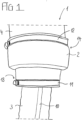
- the pipe connection system 1 described below as an example comprises a pipe connector 2 for connecting a medium pipe 3 of a local or district heating line to an empty pipe 4, into which a section of the medium pipe 3 is inserted, with the pipe connector 2 being connected to the outside of the medium pipe 3 on the one hand and on the other hand, is applied to the empty tube 4 on the outside.
- the pipe connection system 1 further comprises a cable bushing element 5 which can be used optionally with the pipe connector 2 and which has a number of cable bushing openings 6 .
- the cable bushing element 5 is between the pipe connector 2 and the carrier pipe 3, sealing the pipe connection, placed in such a way that it bears against the outer wall 7 of the carrier pipe 3 and the inner wall 8 of the pipe connector 2 at the same time.
- the medium pipe 3 can have an outside diameter of 111 mm or 126 mm, for example.
- the empty pipe 4 can be the straight end of a pipe or the bent end of a pipe act pipe bends.
- the empty pipe 4 can have a diameter of 200 mm, for example.
- the pipe connector 2 is therefore designed in the manner of a reducing sleeve.
- the longitudinal axes of the medium pipe 3 and the empty pipe 4 are slightly inclined to one another. This is possible because the medium pipe 3 used is a flexible medium pipe 3 , in particular designed to be bendable.
- the medium pipe 3 is preferably a flexible composite pipe (PMR), with the inner, media-carrying medium pipe being made of plastic and the outer jacket pipe being made of polyethylene.
- PMR flexible composite pipe
- the pipe connection system 1 comprises a first clamping device 11 in the form of a clamp for applying radially directed pressing forces to a first end section 13 of the pipe connector 2, the first end section 13 being arranged at one end of the pipe connector 2.
- This first clamping device 11 is used to connect the pipe connector 2 to the medium pipe 3.
- the cable bushing element 5 is placed in this first end section 13 between the pipe connector 2 and the medium pipe 3, whereby it is simultaneously pressed against the outer wall 7 of the medium pipe 3 and the inner wall 8 of the pipe connector 2 when the pressing forces are applied, forming a pinch seal.
- the pipe connection system 1 comprises a second clamping device 12, which is different from the first clamping device 11, also in the form of a clamp, which is designed to apply radially directed pressing forces to a second end section 14 of the pipe connector 2, the second end section 14 being attached to the opposite other end of the Pipe connector 2 is arranged.
- This second clamping device 12 is used to connect the pipe connector 2 to the empty pipe 4.
- the carrier pipe 3 used is designed for high mechanical loads, so that clamping only in sections, as described below, has no negative effects on the functionality of the carrier pipe 3.
- the cable bushing element 5 consists of a compressible, preferably elastic material.
- the material of the cable bushing element 5 is preferably a rubber or caoutchouc material, such as an ethylene-propylene-diene rubber (EPDM). It is particularly advantageous if the Shore hardness is between 45 and 55.
- the cable bushing element 5 is preferably designed as a molded part. The material used for the cable bushing element is selected in such a way that it ensures sufficient deformability or compressibility.
- the cable bushing element 5 has a first bearing surface 16 which is designed to bear against the medium pipe 3 .
- it has a second bearing surface 17 which is designed to bear against the pipe connector 2 .
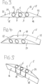
- the number of cable bushing openings 6 in the cable bushing element 5 can vary depending on the length of the cable bushing element 5 .
- the cable bushing element 5 has three cable bushing openings 6 .
- the cable bushing openings 6 are arranged next to one another along the contact surfaces 16 , 17 .
- the cable bushing openings 6 are closed with closures 9 in the form of plugs, which can optionally be removed. Because of the elasticity of the Depending on the material of the cable bushing element 5 , the cable bushing openings 6 can accommodate cables 10 with different external diameters, while at the same time sealing the cable bushing in the region of the cable bushing opening 6 .
- cables 10 with an outer diameter of 10 to 14 mm can be accommodated in cable bushing openings 6 with an inner diameter of 11 mm without the sealing of the pipe connector 2 being impaired as a result.
- a single cable 10 is passed through the cable grommet by passing through the central cable grommet opening 6.
- the cable bushing element 5 has the shape of a flat truncated pyramid with mutually parallel, rectangular base and top surfaces 18, 19 of the same width.
- the longer base surface 18 of the truncated pyramid forms the first contact surface 16 of the cable bushing element 5 and the shorter top surface 19 of the truncated pyramid forms part of the second contact surface 17 of the cable bushing element 5.
- the outer surface of the truncated pyramid consists of two parallel, trapezoidal first side surfaces 21, which connect the longitudinal edges of the base and top surface 18, 19 and through which the cable bushing openings 6 run. as well as two rectangular second side surfaces 22 lying obliquely to one another, connecting the transverse edges of the base and cover surfaces 18, 19 to one another and forming the lateral flanks of the cable bushing element 5. Together with the top surface 19, the side surfaces 22 form the second contact surface 17.
- the base surface 18 of the cable bushing element 5 then lies over the entire surface on the outer wall 7 of the Medium pipe 3, while the top surface 19 and the second side surfaces 22 of the cable bushing element 5 bear against the inner wall 8 of the empty pipe 4 over the entire surface.
- a pinch seal is produced with which the desired tight pipe connection with a cable bushing is realized, with the deformation of the cable bushing element 5 being a compression on both sides, namely perpendicular to the base and top surface 18, 19, and a bend along the longitudinal axis of the cable bushing element 5 comprises.
- the cable bushing openings 6 are slotted.
- the cable bushing openings 6, which are circular in cross-section, are connected to the first contact surface 16 of the cable bushing element 5 via slots 15 running in the axial direction, so that the cable bushing element 5 can be bent open at these points without being damaged to such an extent that a cable 10 to be inserted can be pushed through a widened slot 15 can be inserted into a cable bushing opening 6.
- the assembly of the pipe connector 2 according to the invention, designed as a sealing sleeve, with an additional cable bushing element 5 is particularly simple.
- Empty pipe 4 and pipe connector 2 are already loosely pre-assembled.
- the medium pipe 3 with the number of cables running along it 10 is through the pipe connector 2 is pushed into the empty pipe 4 and the second clamping device 12 on the empty pipe 4 is actuated. This prepares everything for the final assembly step, making the seal.
- the corresponding number of cables 10 to be laid with the medium pipe 3 are inserted into the cable bushing openings 6 of the cable bushing element 5 that has not yet been installed after the closures 9 have been removed from the cable bushing openings 6 of the cable bushing element 5 .
- the slots 15 are opened or bent.
- the cable bushing element 5 is then pushed under the pipe connector 2, namely between the medium pipe 3 and the pipe connector 2, and fixed there with the aid of the first clamping device 11.
- the cable bushing element 5 is arranged between the two components 2, 3 by being pushed along the cable 10 running in the axial direction, parallel to the carrier pipe 3, which lies in the cable bushing openings 6, which are formed by the first side surfaces 21 of the cable bushing element, which are parallel to one another 5 pass through.
- the cable bushing element 5 is placed in such a way that its longitudinal direction is arranged transversely to the axial direction of the medium pipe 3 .
- the cables 10 then run parallel to the medium pipe 3 in the axial direction.
Landscapes
- Engineering & Computer Science (AREA)
- General Engineering & Computer Science (AREA)
- Mechanical Engineering (AREA)
- Architecture (AREA)
- Civil Engineering (AREA)
- Structural Engineering (AREA)
- Installation Of Indoor Wiring (AREA)
Abstract
Description
- Die Erfindung betrifft ein Rohrverbindungssystem mit einer Kabeldurchführung sowie ein Verfahren zum Abdichten einer Rohrverbindung.
- Bei der Anbindung eines Gehäuses an ein Nah- oder Fernwärmenetz wird ein Mediumrohr im Bereich der Bodenplatte in ein Leerrohr geführt. Bei einem Mediumrohr handelt es sich um das Versorgungsrohr einer Fern- oder Nahwärmeleitung, das insbesondere zum Transport warmgehender Medien ausgebildet ist. Beispielsweise ist das Mediumrohr ein flexibles Verbundrohr mit einem Medienrohr aus Kunststoff und einem Mantelrohr aus Polyethylen. Derartige Verbundrohre werden auch mit dem Kürzel PMR (polymeres Mediumrohr) bezeichnet. Da das Mediumrohr typischerweise in einem Sandbett verlegt ist, muß der Übergang zwischen Mediumrohr und Leerrohr zumindest sanddicht abgedichtet werden.
- Herkömmliche Verbindungssysteme, welche eine Abdichtung gewährleisten, wie beispielsweise Dichtflansche, sind zumeist konstruktiv aufwendig und teuer. Dies trifft insbesondere für solche Verbindungssysteme zu, die gleichzeitig auch eine abgedichtete Durchführung von Kabeln bereitstellen, die zusammen mit dem Mediumrohr in das Gebäude hineingeführt werden sollen.
- Eine Aufgabe der vorliegenden Erfindung ist es, eine besonders einfache und preiswerte technische Lösung zum Einführen von Kabeln zusammen mit einem Mediumrohr einer Nah- oder Fernwärmeleitung in ein Leerrohr zu ermöglichen, ohne daß auf eine Abdichtung der Verbindung von Mediumrohr und Leerrohr verzichtet werden muß.
- Diese Aufgabe wird durch ein Rohrverbindungssystem nach Anspruch 1 bzw. durch ein Kabeldurchführungselement nach Anspruch 4 bzw. durch eine Verwendung nach Anspruch 7 bzw. durch ein Verfahren nach Anspruch 8 gelöst.
- Das erfindungsgemäße Rohrverbindungssystem umfaßt einen Rohrverbinder zum Verbinden eines Mediumrohres einer Nah- oder Fernwärmeleitung mit einem Leerrohr, in das ein Abschnitt des Mediumrohres eingeführt ist, wobei der Rohrverbinder nach Art einer Manschette einerseits an das Mediumrohr und andererseits an das Leerrohr anlegbar ist. Das Rohrverbindungssystem umfaßt weiter ein wahlweise mit dem Rohrverbinder verwendbares Kabeldurchführungselement, das eine Anzahl Kabeldurchführungsöffnungen aufweist, wobei das Kabeldurchführungselement zwischen dem Rohrverbinder und dem Mediumrohr, die Rohrverbindung abdichtend, vorzugsweise dabei eine Anzahl Kabel aufnehmend, plazierbar ist derart, daß es gleichzeitig an einer Außenwand des Mediumrohres und an einer Innenwand des Rohrverbinders anliegt.
- Das erfindungsgemäße Kabeldurchführungselement ist zur Verwendung mit einem Rohrverbinder in einem solchen Rohrverbindungssystem ausgebildet und besteht aus einem komprimierbaren, vorzugsweise elastischen Material. Das Kabeldurchführungselement umfaßt eine erste Anlagefläche, ausgebildet zur Anlage an dem Mediumrohr und eine zweite Anlagefläche, ausgebildet zur Anlage an dem Rohrverbinder. Es umfaßt außerdem eine Anzahl Kabeldurchführungsöffnungen.
- Die erfindungsgemäße Verwendung eines Kabeldurchführungselements, welches Kabeldurchführungselement aus einem komprimierbaren, vorzugsweise elastischen Material besteht und eine erste Anlagefläche aufweist, die zur Anlage an einem Mediumrohr ausgebildet ist, und die eine zweite Anlagefläche aufweist, die zur Anlage an einem Rohrverbinder ausgebildet ist, und das eine Anzahl Kabeldurchführungsöffnungenen umfaßt, bezieht sich auf die Verwendung mit einem Rohrverbinder in einem Rohrverbindungssystem derart, daß das Kabeldurchführungselement, eine Anzahl Kabel aufnehmend, zwischen dem Rohrverbinder und dem Mediumrohr, die Rohrverbindung abdichtend, plazierbar ist derart, daß es gleichzeitig an einer Außenwand des Mediumrohres und an einer Innenwand des Rohrverbinders anliegt.
- Das erfindungsgemäße Verfahren zum Abdichten einer Rohrverbindung mit Hilfe eines Rohrverbindungssystems, das einen Rohrverbinder und ein Kabeldurchführungselement umfaßt, weist folgende Schritten auf: Verbinden eines Mediumrohres einer Nah- oder Fernwärmeleitung mit einem Leerrohr, in das ein Abschnitt des Mediumrohres eingeführt ist, wobei der Rohrverbinder nach Art einer Manschette einerseits an das Mediumrohr und andererseits an das Leerrohr angelegt wird; Plazieren des Kabeldurchführungselements, das eine Anzahl Kabeldurchführungsöffnungen aufweist, zwischen dem Rohrverbinder und dem Mediumrohr, die Rohrverbindung abdichtend, derart, daß es gleichzeitig an der Außenwand des Mediumrohres und an der Innenwand des Rohrverbinders anliegt, wobei vor dem Plazieren des Kabeldurchführungselements zwischen dem Rohrverbinder und dem Mediumrohr in wenigstens eine der Kabeldurchführungsöffnungen des Kabeldurchführungselements ein Kabel eingelegt wird.
- Die im Folgenden im Zusammenhang mit dem Rohrverbindungssystem bzw. dem Kabeldurchführungselement erläuterten Vorteile und Ausgestaltungen gelten sinngemäß auch für das erfindungsgemäße Verfahren bzw. die erfindungsgemäße Verwendung und umgekehrt.
- Vorteilhafte Ausführungen der Erfindung sind in den Unteransprüchen angegeben.
- Mit Hilfe des Rohrverbinders, der vorzugsweise nach Art einer Manschette oder Muffe ausgeführt ist, kann eine dichte Verbindung von Mediumrohr und Leerrohr hergestellt werden. Mit Hilfe des zusätzlich verwendeten, außenseitig an dem Mediumrohr anliegenden Kabeldurchführungselements wird ein Einführen von Kabeln zusammen mit dem Mediumrohr in das Leerrohr ermöglicht, ohne daß auf eine Abdichtung der Verbindung von Mediumrohr und Leerrohr verzichtet werden muß.
- Das Kabeldurchführungselement stellt dabei eine dichte Kabeldurchführung entlang eines Teilabschnitts des Rohrumfangs bereit. Im Unterschied zu Dichtungselementen, die das Mediumrohr mantelförmig vollständig umgreifen, wird durch das Einlegen eines lediglich an einem Umfangsabschnitt des Mediumrohres anliegenden Kabeldurchführungselements erreicht, daß - ein Mindestmaß an Flexibilität bzw. Kompressibilität des Mediumrohres vorausgesetzt - ein Standard-Rohrverbinder für die erfindungsgemäße dichte Kabeldurchführung verwendet werden kann, dessen Innendurchmesser auf den Außendurchmesser des Mediumrohres abgestimmt ist, ohne daß ein vergrößerter Außendurchmesser eines mit einem Dichtelement ummantelten Mediumrohres berücksichtigt werden muß.
- Ein weiterer Vorteil besteht darin, daß das Rohrverbindungssystem sowohl mit als auch ohne das Kabeldurchführungselement verwendbar ist, je nachdem, ob eine Kabeldurchführung gewünscht ist oder nicht. Eine kombinierte Anwendung von Kabeldurchführungselement und Rohrverbinder ist nicht zwingend erforderlich.
- Mit anderen Worten kann das Kabeldurchführungselement, da es als separates Bauteil ausgeführt ist, wahlweise mit dem Rohrverbinder verwendet werden, wenn eine abgedichtete Verlegung von Kabeln zusammen mit dem Mediumrohr erfolgen soll. Es ist jedoch ebenfalls möglich, das Kabeldurchführungselement als integralen Teil des Rohrverbinders auszuführen, insbesondere einteilig oder einstückig mit dem Rohrverbinder, so daß das Kabeldurchführungselement dauerhaft an der Innenwand des Rohrverbinders angeordnet ist (kein Teil der beanspruchten Erfindung).
- Gemäß einer vorteilhaften Ausführungsform der Erfindung umfaßt das Rohrverbindungssystem eine Anzahl Klemmvorrichtungen, wobei wenigstens eine erste Klemmvorrichtung zum Aufbringen von vorzugsweise radial gerichteten Preßkräften auf einen ersten Abschnitt des Rohrverbinders ausgebildet ist, zum Verbinden des Rohrverbinders mit dem Mediumrohr, wobei das Kabeldurchführungselement in diesem ersten Abschnitt zwischen dem Rohrverbinder und dem Mediumrohr plazierbar ist, wodurch das Kabeldurchführungselement bei einem Aufbringen der Preßkräfte gleichzeitig gegen die Außenwand des Mediumrohres und die Innenwand des Rohrverbinders gepreßt wird.
- Durch ein mechanisches Aufbringen des Preßdruckes mit Hilfe der Klemmvorrichtung wird das Kabeldurchführungselement zwischen Rohrverbinder und Mediumrohr verklemmt. Die auf diese Weise hergestellte Abdichtung bleibt dauerhaft aufrecht erhalten. Da mit Hilfe der Klemmvorrichtung die Preßkräfte vorzugsweise radial gerichtet sind, erfolgt, bezogen auf die Oberfläche des Mediumrohres, ein gleichmäßiges Anpressen, ohne daß eine unerwünschte Deformation des Mediumrohres auftritt oder die Eigenschaften des Mediumrohres nachteilig verändert werden. Vorzugsweise wird durch das Aufbringen der Preßkräfte eine Quetschdichtung ausgebildet.
- Die mit Hilfe des Kabeldurchführungselements erzielbare Abdichtung gewährleistet zumindest eine sanddichte Abdichtung, so daß ein unerwünschter Materialtransport von der Oberfläche des Mediumrohres in das beispielsweise mit der Bodenplatte vergossene Leerrohr vermieden wird. Je nach Ausführung der beteiligten Komponenten kann auch eine wasserdichte Abdichtung erreicht werden.
- Gemäß einer vorteilhaften Ausführungsform der Erfindung umfaßt das Rohrverbindungssystem eine von der ersten Klemmvorrichtung verschiedene zweite Klemmvorrichtung, ausgebildet zum Aufbringen von vorzugsweise radial gerichteten Preßkräften auf einen zweiten Abschnitt des Rohrverbinders, zum Verbinden des Rohrverbinders mit dem Leerrohr.
- Diese Ausführung ist insbesondere dann vorteilhaft anwendbar, wenn der Rohrverbinder als Reduziermuffe ausgeführt ist. Alternativ kann das Rohrverbindungssystem auch nur eine einzige, dem Rohrverbinder zugeordnete Klemmvorrichtung aufweisen, die dann beide Abschnitte des Rohrverbinders klemmt.
- Bei den ersten und/oder zweiten Klemmvorrichtungen handelt es sich vorzugsweise um herkömmliche Klemmschellen, wie sie beispielsweise als Schlauch- oder Rohrschellen zum Einsatz kommen. Die benötigte Klemm- bzw. Preßkraft wird durch das Anziehen der Klemmschellen auf den Rohrverbinder aufgebracht. Es sind jedoch auch andere Arten von Klemmvorrichtungen verwendbar, vorzugsweise solche, die ebenfalls radial gerichtete Preßkräfte erzeugen können.
- Gemäß einer vorteilhaften Ausführungsform der Erfindung sind die Kabeldurchführungsöffnungen des Kabeldurchführungselements mit wahlweise entfernbaren Verschlüssen verschließbar. Auf diese Weise kann auch dann eine Abdichtung gewährleistet werden, wenn das Kabeldurchführungselement mehrere Kabeldurchführungsöffnungen aufweist, von denen nicht alle für die Durchführung von Kabeln genutzt werden. Die Verschlüsse sind dabei vorzugsweise nach Art von Stopfen ausgeführt, die aus den Kabeldurchführungsöffnungen herausgedrückt werden können.
- Gemäß einer vorteilhaften Ausführungsform der Erfindung weist das Kabeldurchführungselement die Form eines flachen Pyramidenstumpfes auf mit vorzugsweise parallel zueinander liegenden, rechteckigen Grund- und Deckflächen gleicher Breite, wobei die längere Grundfläche des Pyramidenstumpfes die erste Anlagefläche des Kabeldurchführungselements und die kürzere Deckfläche des Pyramidenstumpfes die zweite Anlagefläche des Kabeldurchführungselements bildet. Mit Hilfe einer derartigen geometrischen Ausgestaltung des Kabeldurchführungselements ist eine besonders gute Abdichtungsfunktion gewährleistet, ohne daß die Verwendung des Kabeldurchführungselements als zusätzliches Bauteil innerhalb der Verbindung zwischen Mediumrohr und Leerrohr einen nachteiligen Einfluß auf die mechanische Verbindung zwischen diesen beiden Rohren hat.
- Gemäß einer vorteilhaften Ausführungsform der Erfindung ist der Rohrverbinder, zumindest in seinen von den Klemmvorrichtungen beaufschlagbaren Abschnitten, derart ausgeführt, daß mit Hilfe der Klemmvorrichtungen die benötigten Preßkräfte über den Rohrverbinder auf das Kabeldurchführungselement übertragen werden können. Mit anderen Worten ist der Rohrverbinder in diesen Bereichen derart verformbar, daß die von den Klemmvorrichtungen auf die Außenseite des Rohrverbinders aufgebrachten Klemmkräfte in ausreichendem Maße auf das zwischen Rohrverbinder und Mediumrohr liegende Kabeldurchführungselement übertragen werden können.
- Der Rohrverbinder kann einen gleichbleibenden Innendurchmesser aufweisen. Er kann jedoch auch nach Art einer Reduziermuffe dazu dienen, ein Mediumrohr, das einen geringeren Außendurchmesser aufweist als der Innendurchmesser des Leerrohres, mit einem solchen Leerrohr dicht zu verbinden.
- Die Erfindung ist nicht nur im Zusammenhang mit der Anbindung eines Gehäuses an ein Nah- oder Fernwärmenetz nutzbar. Das erfindungsgemäße Rohrverbindungssystem bzw. das erfindungsgemäße Kabeldurchführungselement kann bei jeder herzustellenden Verbindung zwischen einem Mediumrohr einer Nah- oder Fernwärmeleitung und einem Leerrohr verwendet werden.
- Unter einem Kabel wird ein elektrisches Kabel im Sinne einer elektrischen Leitung verstanden, beispielsweise ein elektrisches Anschlußkabel oder ein Datenkabel. Ein Kabel im Sinne der Erfindung kann jedoch eine beliebige, d.h. auch nichtelektrische, mit dem Mediumrohr zu verlegende Versorgungsleitung vergleichsweise geringen Querschnitts sein, d.h. daß der Querschnitt der zur Durchführung vorgesehenen Versorgungsleitung deutlich geringer ist als der Querschnitt des Mediumrohres.
- Ein Ausführungsbeispiel der Erfindung wird nachfolgend anhand der Zeichnungen näher erläutert. Hierbei zeigen:
- Fig. 1
- eine erste Ansicht eines Rohrverbindungssystems,
- Fig. 2
- eine zweite Ansicht des Rohrverbindungssystems aus
Fig. 1 , - Fig. 3-5
- verschiedene Ansichten eines Kabeldurchführungselements.
- Sämtliche Figuren zeigen die Erfindung nicht maßstabsgerecht, dabei lediglich schematisch und nur mit ihren wesentlichen Bestandteilen. Gleiche Bezugszeichen entsprechen dabei Elementen gleicher oder vergleichbarer Funktion.
- Das nachfolgend beispielhaft beschriebene Rohrverbindungssystem 1 umfaßt eine Rohrverbinder 2 zum Verbinden eines Mediumrohres 3 einer Nah- oder Fernwärmeleitung mit einem Leerrohr 4, in das ein Abschnitt des Mediumrohres 3 eingeführt ist, wobei der Rohrverbinder 2 nach Art einer Manschette einerseits außen an das Mediumrohr 3 und andererseits außen an das Leerrohr 4 angelegt ist. Das Rohrverbindungssystem 1 umfaßt weiterhin ein wahlweise mit dem Rohrverbinder 2 verwendbares Kabeldurchführungselement 5, das eine Anzahl Kabeldurchführungsöffnungen 6 aufweist. Das Kabeldurchführungselement 5 ist zwischen dem Rohrverbinder 2 und dem Mediumrohr 3, die Rohrverbindung abdichtend, plaziert derart, daß es gleichzeitig an der Außenwand 7 des Mediumrohres 3 und an der Innenwand 8 des Rohrverbinders 2 anliegt.
- Das Mediumrohr 3 kann beispielsweise einen Außendurchmesser von 111 mm oder 126 mm haben. Bei dem Leerrohr 4 kann es sich um das gerade Ende eines Rohres oder aber auch das gebogene Ende eines Rohrbogens handeln. Das Leerrohr 4 kann beispielsweise einen Durchmesser von 200 mm haben. Der Rohrverbinder 2 ist daher nach Art einer Reduziermuffe ausgeführt. In dem illustrierten Beispiel liegen die Längsachsen des Mediumrohres 3 und des Leerrohres 4 leicht schräg zueinander. Dies ist möglich, da es sich bei dem verwendeten Mediumrohr 3 um ein flexibles, insbesondere biegbar ausgeführtes Mediumrohr 3 handelt. Vorzugsweise handelt es sich bei dem Mediumrohr 3 um ein flexibles Verbundrohr (PMR), wobei das innere, medienführende Medienrohr aus Kunststoff und das äußere Mantelrohr aus Polyethylen besteht.
- Das Rohrverbindungssystem 1 umfaßt eine erste Klemmvorrichtung 11 in Form einer Klemmschelle zum Aufbringen von radial gerichteten Preßkräften auf einen ersten Endabschnitt 13 des Rohrverbinders 2, wobei der erste Endabschnitt 13 an dem einen Ende des Rohrverbinders 2 angeordnet ist. Diese erste Klemmvorrichtung 11 dient zum Verbinden des Rohrverbinders 2 mit dem Mediumrohr 3.
- Das Kabeldurchführungselement 5 ist in diesem ersten Endabschnitt 13 zwischen dem Rohrverbinder 2 und dem Mediumrohr 3 plaziert, wodurch es bei einem Aufbringen der Preßkräfte unter Ausbildung einer Quetschdichtung gleichzeitig gegen die Außenwand 7 des Mediumrohres 3 und die Innenwand 8 des Rohrverbinders 2 gepreßt wird.
- Das Rohrverbindungssystem 1 umfaßt eine von der ersten Klemmvorrichtung 11 verschiedene zweite Klemmvorrichtung 12, ebenfalls in Form einer Klemmschelle, die zum Aufbringen von radial gerichteten Preßkräften auf einen zweiten Endabschnitt 14 des Rohrverbinders 2 ausgebildet ist, wobei der zweite Endabschnitt 14 an dem gegenüberliegenden anderen Ende des Rohrverbinders 2 angeordnet ist. Diese zweite Klemmvorrichtung 12 dient zum Verbinden des Rohrverbinders 2 mit dem Leerrohr 4.
- Das verwendete Mediumrohr 3 ist für hohe mechanische Belastungen ausgelegt, so daß eine nur abschnittsweise Klemmung, wie nachfolgend beschrieben, keine negativen Auswirkungen auf die Funktionstüchtigkeit des Mediumrohres 3 hat.
- Das Kabeldurchführungselement 5 besteht aus einem komprimierbaren, vorzugsweise elastischen Material. Bei dem Material des Kabeldurchführungselements 5 handelt es sich vorzugsweise um ein Gummi- oder Kautschukmaterial, wie einem Ethylen-Propylen-Dien-Kautschuk (EPDM). Besonders vorteilhaft ist es, wenn die Shore-Härte zwischen 45 und 55 liegt. Vorzugsweise ist das Kabeldurchführungselement 5 als Formteil ausgeführt. Das für das Kabeldurchführungselement verwendete Material ist so gewählt, daß es eine ausreichende Verformbarkeit bzw. Kompressibilität gewährleistet.
- Das Kabeldurchführungselement 5 weist eine erste Anlagefläche 16 auf, die zur Anlage an dem Mediumrohr 3 ausgebildet ist. Außerdem weist es eine zweite Anlagefläche 17 auf, die zur Anlage an dem Rohrverbinder 2 ausgebildet ist.
- Die Anzahl der Kabeldurchführungsöffnungen 6 in dem Kabeldurchführungselement 5 kann in Abhängigkeit von der Länge des Kabeldurchführungselements 5 variieren. Im Beispiel weist das Kabeldurchführungselement 5 drei Kabeldurchführungsöffnungen 6 auf. Die Kabeldurchführungsöffnungen 6 sind entlang der Anlageflächen 16, 17 nebeneinander angeordnet. Die Kabeldurchführungsöffnungen 6 sind mit Verschlüssen 9 in Form von Stopfen verschlossen, die wahlweise entfernt werden können. Aufgrund der Elastizität des Materials des Kabeldurchführungselements 5 können die Kabeldurchführungsöffnungen 6 Kabel 10 mit unterschiedlichen Außendurchmessern, dabei zugleich die Kabeldurchführung im Bereich der Kabeldurchführungsöffnung 6 abdichtend, aufnehmen. So können beispielsweise in Kabeldurchführungsöffnungen 6 mit einem Innendurchmesser von 11 mm Kabel 10 mit einem Außendurchmesser von 10 bis 14 mm aufgenommen werden, ohne hierdurch die Abdichtung des Rohrverbinders 2 beeinträchtigt wird. In den
Fig. 1 und2 ist wird ein einzelnes Kabel 10 durch die Kabeldurchführung hindurchgeführt, indem es durch die mittlere Kabeldurchführungsöffnung 6 hindurchreicht. - Das Kabeldurchführungselement 5 weist die Form eines flachen Pyramidenstumpfes auf mit parallel zueinander liegenden, rechteckigen Grund- und Deckflächen 18, 19 gleicher Breite. Dabei bildet die längere Grundfläche 18 des Pyramidenstumpfes die erste Anlagefläche 16 des Kabeldurchführungselements 5 und die kürzere Deckfläche 19 des Pyramidenstumpfes bildet einen Teil der zweiten Anlagefläche 17 des Kabeldurchführungselements 5.
- Die Mantelfläche des Pyramidenstumpfes setzt sich aufgrund der gleich breiten Grund- und Deckflächen 18, 19 zusammen aus zwei parallel zueinander liegenden, trapezförmigen, die Längskanten der Grund- und Deckfläche 18, 19 miteinander verbindenden ersten Seitenflächen 21, durch die hindurch die Kabeldurchführungsöffnungen 6 verlaufen, sowie aus zwei rechteckigen, schräg zueinander liegenden, die Querkanten der Grund- und Deckfläche 18, 19 miteinander verbindenden zweiten Seitenflächen 22, welche die seitlichen Flanken des Kabeldurchführungselements 5 bilden. Zusammen mit der Deckfläche 19 bilden die Seitenflächen 22 die zweite Anlagefläche 17. Im montierten Zustand liegt dann die Grundfläche 18 des Kabeldurchführungselements 5 vollflächig an der Außenwand 7 des Mediumrohres 3 an, während die Deckfläche 19 und die zweiten Seitenflächen 22 des Kabeldurchführungselements 5 vollflächig an der Innenwand 8 des Leerrohres 4 anliegen. Dabei ist unter Verformung des Kalbedurchführungselements 5 eine Quetschdichtung hergestellt, mit der die gewünschte, eine Kabeldurchführung aufweisende, dichte Rohrverbindung realisiert wird, wobei die Verformung des Kabeldurchführungselements 5 sowohl eine beidseitige, nämlich senkrecht zu der Grund- und Deckfläche 18, 19 verlaufende Kompression als auch eine Biegung entlang der Längsachse des Kabeldurchführungselements 5 umfaßt.
- Das hier beispielhaft beschriebene Kabeldurchführungselement 5 weist folgende Abmessungen auf: Länge der Grundfläche 18 = 130 mm; Länge der Deckfläche 19 = 50 mm; Breite des Kabeldurchführungselements 5 = 30 mm; Höhe des Kabeldurchführungselements 5 = 15 mm.
- Zum einfachen Plazieren der Kabel 10 in dem Kabeldurchführungselement 5 sind die Kabeldurchführungsöffnungen 6 geschlitzt ausgeführt. Die im Querschnitt kreisrunden Kabeldurchführungsöffnungen 6 sind über in Axialrichtung verlaufende Schlitze 15 mit der ersten Anlagefläche 16 des Kabeldurchführungselements 5 verbunden, so daß das Kabeldurchführungselement 5 an diesen Stellen beschädigungslos so weit aufgebogen werden kann, daß sich jeweils ein einzulegendes Kabel 10 durch einen aufgeweiteten Schlitz 15 in eine Kabeldurchführungsöffnung 6 einlegen läßt.
- Die Montage des als Dichtmanschette ausgeführten, erfindungsgemäßen Rohrverbinders 2 mit zusätzlichem Kabeldurchführungselement 5 ist besonders einfach. Leerrohr 4 und Rohrverbinder 2 sind bereits lose vormontiert. Das Mediumrohr 3 mit der Anzahl der daran entlang laufenden Kabel 10 wird durch den Rohrverbinder 2 in das Leerrohr 4 durchgeschoben und die zweite Klemmvorrichtung 12 am Leerrohr 4 wird betätigt. Damit ist alles für den letzten Montageschritt, die Herstellung der Abdichtung, vorbereitet. Die entsprechende, mit dem Mediumrohr 3 zu verlegende Anzahl von Kabeln 10 werden, nachdem die Verschlüsse 9 aus den Kabeldurchführungsöffnungen 6 des Kabeldurchführungselements 5 entfernt wurden, in die Kabeldurchführungsöffnungen 6 des noch nicht montierten Kabeldurchführungselements 5 eingelegt. Zu diesem Zweck werden die Schlitze 15 aufgeklappt bzw. aufgebogen. Anschließend wird das Kabeldurchführungselement 5 unter den Rohrverbinder 2 geschoben, nämlich zwischen Mediumrohr 3 und Rohrverbinder 2, und dort mit Hilfe der ersten Klemmvorrichtung 11 fixiert. Dabei wird das Kabeldurchführungselement 5 zwischen den beiden Bauteilen 2, 3 angeordnet, indem es entlang der in Axialrichtung, parallel zu dem Mediumrohr 3 verlaufenden Kabel 10 verschoben wird, die in den Kabeldurchführungsöffnungen 6 einliegen, welche durch die parallel zueinander liegenden ersten Seitenflächen 21 des Kabeldurchführungselements 5 hindurch verlaufen. Anders ausgedrückt wird das Kabeldurchführungselement 5 derart plaziert, daß seine Längsrichtung quer zu der axialen Richtung des Mediumrohres 3 angeordnet ist. Die Kabel 10 verlaufen dann parallel mit dem Mediumrohr 3 in axialer Richtung.
- Erfolgt das Einlegen der Kabel 10 in die Kabeldurchführungsöffnungen 6 bei noch nicht montiertem Kabeldurchführungselement 5, wird die Montage der Abdichtung wesentlich erleichtert. Es entfällt ein "Einfädeln" der Kabel in ein bereits montiertes Kabeldurchführungselement. Selbstverständlich ist es aber auch möglich, die Kabel 10 nachträglich in ein bereits zwischen Mediumrohr 3 und Rohrverbinder 2 plaziertes Kabeldurchführungselement 5 einzuführen; in diesem Fall werden keine Schlitze 15 benötigt.
- Alle in der Beschreibung, den nachfolgenden Ansprüchen und der Zeichnung dargestellten Merkmale können sowohl einzeln als auch in beliebiger Kombination miteinander erfindungswesentlich sein. Diese Merkmale bzw. Merkmalskombinationen können jeweils eine selbständige Erfindung begründen, deren Inanspruchnahme ausdrücklich vorbehalten ist.
- Bei der Angabe einer eine Erfindung definierenden Merkmalskombination müssen einzelne Merkmale aus der Beschreibung eines Ausführungsbeispiels nicht zwingend mit einem oder mehreren oder allen anderen in der Beschreibung dieses Ausführungsbeispiels angegebenen Merkmalen kombiniert werden; diesbezüglich ist jede Unterkombination von Merkmalen eines oder mehrerer Ausführungsbeispiele ausdrücklich mitoffenbart.
- Außerdem können gegenständliche Merkmale der Vorrichtung umformuliert als Verfahrensmerkmale Verwendung finden und Verfahrensmerkmale können umformuliert als gegenständliche Merkmale der Vorrichtung Verwendung finden. Auf diese Weise umformulierte Merkmale sind implizit mitoffenbart.
-
- 1
- Rohrverbindungssystem
- 2
- Rohrverbinder
- 3
- Mediumrohr
- 4
- Leerrohr
- 5
- Kabeldurchführungselement
- 6
- Kabeldurchführungsöffnung
- 7
- Außenwand des Mediumrohres
- 8
- Innenwand des Rohrverbinders
- 9
- Verschlußstopfen
- 10
- Kabel
- 11
- erste Klemmvorrichtung
- 12
- zweite Klemmvorrichtung
- 13
- erster Endabschnitt
- 14
- zweiter Endabschnitt
- 15
- Schlitz
- 16
- erste Anlagefläche
- 17
- zweite Anlagefläche
- 18
- Grundfläche
- 19
- Deckfläche
- 20
- (frei)
- 21
- erste Seitenfläche
- 22
- zweite Seitenfläche
Claims (9)
- Rohrverbindungssystem (1), mit einem Rohrverbinder (2) zum Verbinden eines Mediumrohres (3) einer Nah- oder Fernwärmeleitung mit einem Leerrohr (4), in das ein Abschnitt des Mediumrohres (3) eingeführt ist, wobei der Rohrverbinder (2) nach Art einer Manschette einerseits an das Mediumrohr (3) und andererseits an das Leerrohr (4) anlegbar ist, und mit einem Kabeldurchführungselement (5), das eine Anzahl Kabeldurchführungsöffnungen (6) aufweist, welches Kabeldurchführungselement (5) zwischen dem Rohrverbinder (2) und dem Mediumrohr (3), die Rohrverbindung abdichtend, plazierbar ist derart, daß es gleichzeitig an der Außenwand (7) des Mediumrohres (3) und an der Innenwand (8) des Rohrverbinders (2) anliegt.
- Rohrverbindungssystem (1) nach Anspruch 1, mit einer Anzahl Klemmvorrichtungen (11, 12), wobei wenigstens eine erste Klemmvorrichtung (11) zum Aufbringen von vorzugsweise radial gerichteten Preßkräften auf einen ersten Abschnitt (13) des Rohrverbinders (2) ausgebildet ist, zum Verbinden des Rohrverbinders (2) mit dem Mediumrohr (3), wobei das Kabeldurchführungselement (5) in diesem ersten Abschnitt (13) zwischen dem Rohrverbinder (2) und dem Mediumrohr (3) plazierbar ist, wodurch es bei einem Aufbringen der Preßkräfte gleichzeitig gegen die Außenwand (7) des Mediumrohres (3) und die Innenwand (8) des Rohrverbinders (2) gepreßt wird.
- Rohrverbindungssystem (1) nach Anspruch 2, mit einer von der ersten Klemmvorrichtung (11) verschiedenen zweiten Klemmvorrichtung (12), ausgebildet zum Aufbringen von Preßkräften auf einen zweiten Abschnitt (14) des Rohrverbinders (2), zum Verbinden des Rohrverbinders (2) mit dem Leerrohr (4).
- Kabeldurchführungselement (5), ausgebildet zur Verwendung mit einem Rohrverbinder (2) in einem Rohrverbindungssystem (1) nach einem der Ansprüche 1 bis 3, bestehend aus einem komprimierbaren, vorzugsweise elastischen Material, mit einer ersten Anlagefläche (16), ausgebildet zur Anlage an dem Mediumrohr (3) und mit einer zweiten Anlagefläche (17), ausgebildet zur Anlage an dem Rohrverbinder (2), und mit einer Anzahl Kabeldurchführungsöffnungen (6).
- Kabeldurchführungselement (5) nach Anspruch 4, wobei die Kabeldurchführungsöffnungen (6) mit wahlweise entfernbaren Verschlüssen (9) verschließbar sind.
- Kabeldurchführungselement (5) nach Anspruch 4 oder 5, wobei es die Form eines flachen Pyramidenstumpfes aufweist mit vorzugsweise parallel zueinander liegenden, rechteckigen Grund- und Deckflächen (18, 19) gleicher Breite, wobei die längere Grundfläche (18) des Pyramidenstumpfes die erste Anlagefläche (16) des Kabeldurchführungselements (5) und die kürzere Deckfläche (19) des Pyramidenstumpfes die zweite Anlagefläche (17) des Kabeldurchführungselements (5) bildet.
- Verwendung eines Kabeldurchführungselements (5) mit einem Rohrverbinder (2) in einem Rohrverbindungssystem (1) derart, daß das Kabeldurchführungselement (5), eine Anzahl Kabel (10) aufnehmend, zwischen dem Rohrverbinder (2) und einem Mediumrohr (3) einer Nah- oder Fernwärmeleitung, die Rohrverbindung abdichtend, plazierbar ist derart, daß es gleichzeitig an einer Außenwand (7) des Mediumrohres (3) und an einer Innenwand (8) des Rohrverbinders (2) anliegt, wobei das Kabeldurchführungselement (5) aus einem komprimierbaren, vorzugsweise elastischen Material besteht und eine erste Anlagefläche (16) aufweist, die zur Anlage an dem Mediumrohr (3) ausgebildet ist, und die eine zweite Anlagefläche (17) aufweist, die zur Anlage an dem Rohrverbinder (2) ausgebildet ist, und das eine Anzahl Kabeldurchführungsöffnungen (6) umfaßt.
- Verfahren zum Abdichten einer Rohrverbindung mit Hilfe eines Rohrverbindungssystems (1), das einen Rohrverbinder (2) und ein Kabeldurchführungselement (5) umfaßt, mit den Schritten:Verbinden eines Mediumrohres (3) einer Nah- oder Fernwärmeleitung mit einem Leerrohr (4), in das ein Abschnitt des Mediumrohres (3) eingeführt ist, wobei der Rohrverbinder (2) nach Art einer Manschette einerseits an das Mediumrohr (3) und andererseits an das Leerrohr (4) angelegt wird,Plazieren des Kabeldurchführungselements (5), das eine Anzahl Kabeldurchführungsöffnungen (6) aufweist, zwischen dem Rohrverbinder (2) und dem Mediumrohr (3), die Rohrverbindung abdichtend, derart, daß es gleichzeitig an der Außenwand (7) des Mediumrohres (3) und an der Innenwand (8) des Rohrverbinders (2) anliegt,wobei vor dem Plazieren des Kabeldurchführungselements (5) zwischen dem Rohrverbinder (2) und dem Mediumrohr (3) in wenigstens eine der Kabeldurchführungsöffnungen (6) des Kabeldurchführungselements (5) ein Kabel (10) eingelegt wird.
- Verfahren nach Anspruch 8, wobei das Kabel (10) durch einen Schlitz (15) in dem Kabeldurchführungselement (5) in die Kabeldurchführungsöffnung (6) eingelegt wird.
Applications Claiming Priority (1)
| Application Number | Priority Date | Filing Date | Title |
|---|---|---|---|
| DE102021120824.6A DE102021120824A1 (de) | 2021-08-10 | 2021-08-10 | Rohrverbindungssystem |
Publications (2)
| Publication Number | Publication Date |
|---|---|
| EP4134579A1 true EP4134579A1 (de) | 2023-02-15 |
| EP4134579B1 EP4134579B1 (de) | 2024-07-10 |
Family
ID=82786747
Family Applications (1)
| Application Number | Title | Priority Date | Filing Date |
|---|---|---|---|
| EP22020371.5A Active EP4134579B1 (de) | 2021-08-10 | 2022-08-03 | Rohrverbindungssystem, verwendung und verfahren |
Country Status (2)
| Country | Link |
|---|---|
| EP (1) | EP4134579B1 (de) |
| DE (1) | DE102021120824A1 (de) |
Citations (6)
| Publication number | Priority date | Publication date | Assignee | Title |
|---|---|---|---|---|
| GB1220515A (en) * | 1967-06-23 | 1971-01-27 | Pneumatiques Caoutchouc Mfg | Closure members for pipe sections |
| US4109097A (en) * | 1977-03-01 | 1978-08-22 | Crouse-Hinds Company | Expansion-deflection coupling |
| US5193859A (en) * | 1989-09-28 | 1993-03-16 | Mckinnon Robert M | Reinforced pipe coupling member |
| FR3021385A1 (fr) * | 2014-05-23 | 2015-11-27 | Itp Sa | Troncon pour un conduit double enveloppe monte par vissage thermiquement isole et chauffe et son procede de mise en oeuvre |
| DE202016101248U1 (de) * | 2016-03-08 | 2017-06-09 | Angela Haas | Reduzierstück |
| US20210108744A1 (en) * | 2019-10-14 | 2021-04-15 | Fernco, Inc. | Pipe coupling apparatus |
-
2021
- 2021-08-10 DE DE102021120824.6A patent/DE102021120824A1/de active Pending
-
2022
- 2022-08-03 EP EP22020371.5A patent/EP4134579B1/de active Active
Patent Citations (6)
| Publication number | Priority date | Publication date | Assignee | Title |
|---|---|---|---|---|
| GB1220515A (en) * | 1967-06-23 | 1971-01-27 | Pneumatiques Caoutchouc Mfg | Closure members for pipe sections |
| US4109097A (en) * | 1977-03-01 | 1978-08-22 | Crouse-Hinds Company | Expansion-deflection coupling |
| US5193859A (en) * | 1989-09-28 | 1993-03-16 | Mckinnon Robert M | Reinforced pipe coupling member |
| FR3021385A1 (fr) * | 2014-05-23 | 2015-11-27 | Itp Sa | Troncon pour un conduit double enveloppe monte par vissage thermiquement isole et chauffe et son procede de mise en oeuvre |
| DE202016101248U1 (de) * | 2016-03-08 | 2017-06-09 | Angela Haas | Reduzierstück |
| US20210108744A1 (en) * | 2019-10-14 | 2021-04-15 | Fernco, Inc. | Pipe coupling apparatus |
Also Published As
| Publication number | Publication date |
|---|---|
| DE102021120824A1 (de) | 2023-02-16 |
| EP4134579B1 (de) | 2024-07-10 |
Similar Documents
| Publication | Publication Date | Title |
|---|---|---|
| DE69714737T2 (de) | Modulare dichtungsanordnung für eine wandöffnung | |
| DE3512175C2 (de) | ||
| DE69514934T2 (de) | Verbindung | |
| DE3003040A1 (de) | Rohrkupplung | |
| DE19654435A1 (de) | Anordnung zur steckbaren Verbindung von Rohren mit Armaturen oder Fittings | |
| EP3329567A1 (de) | Explosionsgeschützte anordnung und verfahren zu deren herstellung | |
| EP0655817B1 (de) | Schraubbare Einführungsvorrichtung für Muffen oder Gehäuse | |
| DE69836553T2 (de) | Kuppelstück für rohre | |
| DE3782514T2 (de) | Methode und vorrichtung zum abdichten von kabeln. | |
| EP3940281B1 (de) | Rohrmuffe | |
| DE102013224027B4 (de) | Durchführungsvorrichtung für Leitungen, insbesondere Hauseinführung | |
| EP4134579B1 (de) | Rohrverbindungssystem, verwendung und verfahren | |
| DE10349440B4 (de) | Dichte Wanddurchführung mit Zugentlastung | |
| DE102018118763A1 (de) | Dichtungsmodul und Dichtungsanordnung mit einem oder mehreren Dichtungsmodulen | |
| DE69402062T2 (de) | Kabeldichtung und sicherungsvorrichtung | |
| EP1313981B1 (de) | Verbindungseinrichtung für schutzrohre | |
| EP3544132B1 (de) | Axial fixierbare dichtungsanordnung für eine kabeldurchführung | |
| EP1201014B1 (de) | Universale kabelgarnitur | |
| DE69121548T2 (de) | Verbesserte Bandschelle mit keilförmigen, geschlitzten Nocken | |
| DE102010009618A1 (de) | Anschlussvorrichtung für ein modulares Installationssystem | |
| DE19743185A1 (de) | Vorrichtung zum Anschließen von Rohrleitungen | |
| DE102015220685A1 (de) | Zugentlastungselement für eine Leitung, Aufnahmeeinrichtung, Zugentlastungsvorrichtung und Gehäuse | |
| DE102023210818B4 (de) | Verfahren zur Anbringung einer Tülle an einem Leitungsstrang, Gießform, Set und Anordnung aus Tülle und Leitungsstrang | |
| DE29508725U1 (de) | Anordnung zur Abdichtung des Einführungsbereiches eines langgestreckten Substrates | |
| EP0584616A2 (de) | Anordnung für Mehrfachkabeleinführungen bei Kabelmuffen |
Legal Events
| Date | Code | Title | Description |
|---|---|---|---|
| PUAI | Public reference made under article 153(3) epc to a published international application that has entered the european phase |
Free format text: ORIGINAL CODE: 0009012 |
|
| STAA | Information on the status of an ep patent application or granted ep patent |
Free format text: STATUS: THE APPLICATION HAS BEEN PUBLISHED |
|
| AK | Designated contracting states |
Kind code of ref document: A1 Designated state(s): AL AT BE BG CH CY CZ DE DK EE ES FI FR GB GR HR HU IE IS IT LI LT LU LV MC MK MT NL NO PL PT RO RS SE SI SK SM TR |
|
| PUAJ | Public notification under rule 129 epc |
Free format text: ORIGINAL CODE: 0009425 |
|
| 32PN | Public notification |
Free format text: MITTEILUNG GEMAESS REGEL 69 EPU- ERINERUNG AN DIE ZAHLUNG DER BENENNUNGSGEBUEHR SOWIE PRUEFUENGSGEBUEHR UND AUFFORDERUNG NACH REGEL 70A(1) EPUE |
|
| P01 | Opt-out of the competence of the unified patent court (upc) registered |
Effective date: 20230528 |
|
| STAA | Information on the status of an ep patent application or granted ep patent |
Free format text: STATUS: REQUEST FOR EXAMINATION WAS MADE |
|
| 17P | Request for examination filed |
Effective date: 20230720 |
|
| RBV | Designated contracting states (corrected) |
Designated state(s): AL AT BE BG CH CY CZ DE DK EE ES FI FR GB GR HR HU IE IS IT LI LT LU LV MC MK MT NL NO PL PT RO RS SE SI SK SM TR |
|
| GRAJ | Information related to disapproval of communication of intention to grant by the applicant or resumption of examination proceedings by the epo deleted |
Free format text: ORIGINAL CODE: EPIDOSDIGR1 |
|
| GRAP | Despatch of communication of intention to grant a patent |
Free format text: ORIGINAL CODE: EPIDOSNIGR1 |
|
| GRAP | Despatch of communication of intention to grant a patent |
Free format text: ORIGINAL CODE: EPIDOSNIGR1 |
|
| STAA | Information on the status of an ep patent application or granted ep patent |
Free format text: STATUS: GRANT OF PATENT IS INTENDED |
|
| RIC1 | Information provided on ipc code assigned before grant |
Ipc: H02G 3/22 20060101ALN20240129BHEP Ipc: H02G 3/04 20060101ALN20240129BHEP Ipc: H02G 3/06 20060101ALI20240129BHEP Ipc: F16L 27/10 20060101ALI20240129BHEP Ipc: F16L 25/14 20060101AFI20240129BHEP |
|
| RIC1 | Information provided on ipc code assigned before grant |
Ipc: H02G 3/22 20060101ALN20240205BHEP Ipc: H02G 3/04 20060101ALN20240205BHEP Ipc: H02G 3/06 20060101ALI20240205BHEP Ipc: F16L 27/10 20060101ALI20240205BHEP Ipc: F16L 25/14 20060101AFI20240205BHEP |
|
| INTG | Intention to grant announced |
Effective date: 20240220 |
|
| RIC1 | Information provided on ipc code assigned before grant |
Ipc: H02G 3/22 20060101ALN20240212BHEP Ipc: H02G 3/04 20060101ALN20240212BHEP Ipc: H02G 3/06 20060101ALI20240212BHEP Ipc: F16L 27/10 20060101ALI20240212BHEP Ipc: F16L 25/14 20060101AFI20240212BHEP |
|
| GRAS | Grant fee paid |
Free format text: ORIGINAL CODE: EPIDOSNIGR3 |
|
| GRAA | (expected) grant |
Free format text: ORIGINAL CODE: 0009210 |
|
| STAA | Information on the status of an ep patent application or granted ep patent |
Free format text: STATUS: THE PATENT HAS BEEN GRANTED |
|
| AK | Designated contracting states |
Kind code of ref document: B1 Designated state(s): AL AT BE BG CH CY CZ DE DK EE ES FI FR GB GR HR HU IE IS IT LI LT LU LV MC MK MT NL NO PL PT RO RS SE SI SK SM TR |
|
| REG | Reference to a national code |
Ref country code: CH Ref legal event code: EP |
|
| REG | Reference to a national code |
Ref country code: DE Ref legal event code: R096 Ref document number: 502022001182 Country of ref document: DE |
|
| REG | Reference to a national code |
Ref country code: LT Ref legal event code: MG9D |
|
| REG | Reference to a national code |
Ref country code: NL Ref legal event code: MP Effective date: 20240710 |
|
| PG25 | Lapsed in a contracting state [announced via postgrant information from national office to epo] |
Ref country code: PT Free format text: LAPSE BECAUSE OF FAILURE TO SUBMIT A TRANSLATION OF THE DESCRIPTION OR TO PAY THE FEE WITHIN THE PRESCRIBED TIME-LIMIT Effective date: 20241111 |
|
| PG25 | Lapsed in a contracting state [announced via postgrant information from national office to epo] |
Ref country code: NL Free format text: LAPSE BECAUSE OF FAILURE TO SUBMIT A TRANSLATION OF THE DESCRIPTION OR TO PAY THE FEE WITHIN THE PRESCRIBED TIME-LIMIT Effective date: 20240710 |
|
| PG25 | Lapsed in a contracting state [announced via postgrant information from national office to epo] |
Ref country code: PT Free format text: LAPSE BECAUSE OF FAILURE TO SUBMIT A TRANSLATION OF THE DESCRIPTION OR TO PAY THE FEE WITHIN THE PRESCRIBED TIME-LIMIT Effective date: 20241111 Ref country code: NL Free format text: LAPSE BECAUSE OF FAILURE TO SUBMIT A TRANSLATION OF THE DESCRIPTION OR TO PAY THE FEE WITHIN THE PRESCRIBED TIME-LIMIT Effective date: 20240710 |
|
| PG25 | Lapsed in a contracting state [announced via postgrant information from national office to epo] |
Ref country code: NO Free format text: LAPSE BECAUSE OF FAILURE TO SUBMIT A TRANSLATION OF THE DESCRIPTION OR TO PAY THE FEE WITHIN THE PRESCRIBED TIME-LIMIT Effective date: 20241010 |
|
| PG25 | Lapsed in a contracting state [announced via postgrant information from national office to epo] |
Ref country code: GR Free format text: LAPSE BECAUSE OF FAILURE TO SUBMIT A TRANSLATION OF THE DESCRIPTION OR TO PAY THE FEE WITHIN THE PRESCRIBED TIME-LIMIT Effective date: 20241011 Ref country code: FI Free format text: LAPSE BECAUSE OF FAILURE TO SUBMIT A TRANSLATION OF THE DESCRIPTION OR TO PAY THE FEE WITHIN THE PRESCRIBED TIME-LIMIT Effective date: 20240710 Ref country code: PL Free format text: LAPSE BECAUSE OF FAILURE TO SUBMIT A TRANSLATION OF THE DESCRIPTION OR TO PAY THE FEE WITHIN THE PRESCRIBED TIME-LIMIT Effective date: 20240710 |
|
| PG25 | Lapsed in a contracting state [announced via postgrant information from national office to epo] |
Ref country code: BG Free format text: LAPSE BECAUSE OF FAILURE TO SUBMIT A TRANSLATION OF THE DESCRIPTION OR TO PAY THE FEE WITHIN THE PRESCRIBED TIME-LIMIT Effective date: 20240710 |
|
| PG25 | Lapsed in a contracting state [announced via postgrant information from national office to epo] |
Ref country code: LV Free format text: LAPSE BECAUSE OF FAILURE TO SUBMIT A TRANSLATION OF THE DESCRIPTION OR TO PAY THE FEE WITHIN THE PRESCRIBED TIME-LIMIT Effective date: 20240710 |
|
| PG25 | Lapsed in a contracting state [announced via postgrant information from national office to epo] |
Ref country code: IS Free format text: LAPSE BECAUSE OF FAILURE TO SUBMIT A TRANSLATION OF THE DESCRIPTION OR TO PAY THE FEE WITHIN THE PRESCRIBED TIME-LIMIT Effective date: 20241110 |
|
| PG25 | Lapsed in a contracting state [announced via postgrant information from national office to epo] |
Ref country code: HR Free format text: LAPSE BECAUSE OF FAILURE TO SUBMIT A TRANSLATION OF THE DESCRIPTION OR TO PAY THE FEE WITHIN THE PRESCRIBED TIME-LIMIT Effective date: 20240710 |
|
| PG25 | Lapsed in a contracting state [announced via postgrant information from national office to epo] |
Ref country code: ES Free format text: LAPSE BECAUSE OF FAILURE TO SUBMIT A TRANSLATION OF THE DESCRIPTION OR TO PAY THE FEE WITHIN THE PRESCRIBED TIME-LIMIT Effective date: 20240710 Ref country code: RS Free format text: LAPSE BECAUSE OF FAILURE TO SUBMIT A TRANSLATION OF THE DESCRIPTION OR TO PAY THE FEE WITHIN THE PRESCRIBED TIME-LIMIT Effective date: 20241010 |
|
| PG25 | Lapsed in a contracting state [announced via postgrant information from national office to epo] |
Ref country code: RS Free format text: LAPSE BECAUSE OF FAILURE TO SUBMIT A TRANSLATION OF THE DESCRIPTION OR TO PAY THE FEE WITHIN THE PRESCRIBED TIME-LIMIT Effective date: 20241010 Ref country code: PL Free format text: LAPSE BECAUSE OF FAILURE TO SUBMIT A TRANSLATION OF THE DESCRIPTION OR TO PAY THE FEE WITHIN THE PRESCRIBED TIME-LIMIT Effective date: 20240710 Ref country code: NO Free format text: LAPSE BECAUSE OF FAILURE TO SUBMIT A TRANSLATION OF THE DESCRIPTION OR TO PAY THE FEE WITHIN THE PRESCRIBED TIME-LIMIT Effective date: 20241010 Ref country code: LV Free format text: LAPSE BECAUSE OF FAILURE TO SUBMIT A TRANSLATION OF THE DESCRIPTION OR TO PAY THE FEE WITHIN THE PRESCRIBED TIME-LIMIT Effective date: 20240710 Ref country code: IS Free format text: LAPSE BECAUSE OF FAILURE TO SUBMIT A TRANSLATION OF THE DESCRIPTION OR TO PAY THE FEE WITHIN THE PRESCRIBED TIME-LIMIT Effective date: 20241110 Ref country code: HR Free format text: LAPSE BECAUSE OF FAILURE TO SUBMIT A TRANSLATION OF THE DESCRIPTION OR TO PAY THE FEE WITHIN THE PRESCRIBED TIME-LIMIT Effective date: 20240710 Ref country code: GR Free format text: LAPSE BECAUSE OF FAILURE TO SUBMIT A TRANSLATION OF THE DESCRIPTION OR TO PAY THE FEE WITHIN THE PRESCRIBED TIME-LIMIT Effective date: 20241011 Ref country code: FI Free format text: LAPSE BECAUSE OF FAILURE TO SUBMIT A TRANSLATION OF THE DESCRIPTION OR TO PAY THE FEE WITHIN THE PRESCRIBED TIME-LIMIT Effective date: 20240710 Ref country code: ES Free format text: LAPSE BECAUSE OF FAILURE TO SUBMIT A TRANSLATION OF THE DESCRIPTION OR TO PAY THE FEE WITHIN THE PRESCRIBED TIME-LIMIT Effective date: 20240710 Ref country code: BG Free format text: LAPSE BECAUSE OF FAILURE TO SUBMIT A TRANSLATION OF THE DESCRIPTION OR TO PAY THE FEE WITHIN THE PRESCRIBED TIME-LIMIT Effective date: 20240710 |
|
| REG | Reference to a national code |
Ref country code: DE Ref legal event code: R097 Ref document number: 502022001182 Country of ref document: DE |
|
| PG25 | Lapsed in a contracting state [announced via postgrant information from national office to epo] |
Ref country code: SM Free format text: LAPSE BECAUSE OF FAILURE TO SUBMIT A TRANSLATION OF THE DESCRIPTION OR TO PAY THE FEE WITHIN THE PRESCRIBED TIME-LIMIT Effective date: 20240710 Ref country code: DK Free format text: LAPSE BECAUSE OF FAILURE TO SUBMIT A TRANSLATION OF THE DESCRIPTION OR TO PAY THE FEE WITHIN THE PRESCRIBED TIME-LIMIT Effective date: 20240710 Ref country code: RO Free format text: LAPSE BECAUSE OF FAILURE TO SUBMIT A TRANSLATION OF THE DESCRIPTION OR TO PAY THE FEE WITHIN THE PRESCRIBED TIME-LIMIT Effective date: 20240710 |
|
| PG25 | Lapsed in a contracting state [announced via postgrant information from national office to epo] |
Ref country code: LU Free format text: LAPSE BECAUSE OF NON-PAYMENT OF DUE FEES Effective date: 20240803 |
|
| PG25 | Lapsed in a contracting state [announced via postgrant information from national office to epo] |
Ref country code: MC Free format text: LAPSE BECAUSE OF FAILURE TO SUBMIT A TRANSLATION OF THE DESCRIPTION OR TO PAY THE FEE WITHIN THE PRESCRIBED TIME-LIMIT Effective date: 20240710 Ref country code: EE Free format text: LAPSE BECAUSE OF FAILURE TO SUBMIT A TRANSLATION OF THE DESCRIPTION OR TO PAY THE FEE WITHIN THE PRESCRIBED TIME-LIMIT Effective date: 20240710 |
|
| PG25 | Lapsed in a contracting state [announced via postgrant information from national office to epo] |
Ref country code: CZ Free format text: LAPSE BECAUSE OF FAILURE TO SUBMIT A TRANSLATION OF THE DESCRIPTION OR TO PAY THE FEE WITHIN THE PRESCRIBED TIME-LIMIT Effective date: 20240710 |
|
| PG25 | Lapsed in a contracting state [announced via postgrant information from national office to epo] |
Ref country code: SK Free format text: LAPSE BECAUSE OF FAILURE TO SUBMIT A TRANSLATION OF THE DESCRIPTION OR TO PAY THE FEE WITHIN THE PRESCRIBED TIME-LIMIT Effective date: 20240710 Ref country code: IT Free format text: LAPSE BECAUSE OF FAILURE TO SUBMIT A TRANSLATION OF THE DESCRIPTION OR TO PAY THE FEE WITHIN THE PRESCRIBED TIME-LIMIT Effective date: 20240710 |
|
| PLBE | No opposition filed within time limit |
Free format text: ORIGINAL CODE: 0009261 |
|
| STAA | Information on the status of an ep patent application or granted ep patent |
Free format text: STATUS: NO OPPOSITION FILED WITHIN TIME LIMIT |
|
| 26N | No opposition filed |
Effective date: 20250411 |
|
| REG | Reference to a national code |
Ref country code: BE Ref legal event code: MM Effective date: 20240831 |
|
| PG25 | Lapsed in a contracting state [announced via postgrant information from national office to epo] |
Ref country code: BE Free format text: LAPSE BECAUSE OF NON-PAYMENT OF DUE FEES Effective date: 20240831 |
|
| PG25 | Lapsed in a contracting state [announced via postgrant information from national office to epo] |
Ref country code: FR Free format text: LAPSE BECAUSE OF NON-PAYMENT OF DUE FEES Effective date: 20240910 |
|
| PG25 | Lapsed in a contracting state [announced via postgrant information from national office to epo] |
Ref country code: IE Free format text: LAPSE BECAUSE OF NON-PAYMENT OF DUE FEES Effective date: 20240803 |
|
| PG25 | Lapsed in a contracting state [announced via postgrant information from national office to epo] |
Ref country code: SE Free format text: LAPSE BECAUSE OF FAILURE TO SUBMIT A TRANSLATION OF THE DESCRIPTION OR TO PAY THE FEE WITHIN THE PRESCRIBED TIME-LIMIT Effective date: 20240710 |
|
| PGFP | Annual fee paid to national office [announced via postgrant information from national office to epo] |
Ref country code: DE Payment date: 20250804 Year of fee payment: 4 |
|
| PGFP | Annual fee paid to national office [announced via postgrant information from national office to epo] |
Ref country code: AT Payment date: 20251020 Year of fee payment: 4 |
|
| PGFP | Annual fee paid to national office [announced via postgrant information from national office to epo] |
Ref country code: CH Payment date: 20250901 Year of fee payment: 4 |
|
| PG25 | Lapsed in a contracting state [announced via postgrant information from national office to epo] |
Ref country code: CY Free format text: LAPSE BECAUSE OF FAILURE TO SUBMIT A TRANSLATION OF THE DESCRIPTION OR TO PAY THE FEE WITHIN THE PRESCRIBED TIME-LIMIT; INVALID AB INITIO Effective date: 20220803 |
|
| PG25 | Lapsed in a contracting state [announced via postgrant information from national office to epo] |
Ref country code: HU Free format text: LAPSE BECAUSE OF FAILURE TO SUBMIT A TRANSLATION OF THE DESCRIPTION OR TO PAY THE FEE WITHIN THE PRESCRIBED TIME-LIMIT; INVALID AB INITIO Effective date: 20220803 |