EP4134581A1 - Conduite flexible isolé et procédé de fabrication d'une telle conduite - Google Patents
Conduite flexible isolé et procédé de fabrication d'une telle conduite Download PDFInfo
- Publication number
- EP4134581A1 EP4134581A1 EP21190596.3A EP21190596A EP4134581A1 EP 4134581 A1 EP4134581 A1 EP 4134581A1 EP 21190596 A EP21190596 A EP 21190596A EP 4134581 A1 EP4134581 A1 EP 4134581A1
- Authority
- EP
- European Patent Office
- Prior art keywords
- pipe
- thermal insulation
- film
- casing
- medium pipe
- Prior art date
- Legal status (The legal status is an assumption and is not a legal conclusion. Google has not performed a legal analysis and makes no representation as to the accuracy of the status listed.)
- Granted
Links
Images

Classifications
-
- F—MECHANICAL ENGINEERING; LIGHTING; HEATING; WEAPONS; BLASTING
- F16—ENGINEERING ELEMENTS AND UNITS; GENERAL MEASURES FOR PRODUCING AND MAINTAINING EFFECTIVE FUNCTIONING OF MACHINES OR INSTALLATIONS; THERMAL INSULATION IN GENERAL
- F16L—PIPES; JOINTS OR FITTINGS FOR PIPES; SUPPORTS FOR PIPES, CABLES OR PROTECTIVE TUBING; MEANS FOR THERMAL INSULATION IN GENERAL
- F16L59/00—Thermal insulation in general
- F16L59/14—Arrangements for the insulation of pipes or pipe systems
- F16L59/153—Arrangements for the insulation of pipes or pipe systems for flexible pipes
-
- B—PERFORMING OPERATIONS; TRANSPORTING
- B29—WORKING OF PLASTICS; WORKING OF SUBSTANCES IN A PLASTIC STATE IN GENERAL
- B29C—SHAPING OR JOINING OF PLASTICS; SHAPING OF MATERIAL IN A PLASTIC STATE, NOT OTHERWISE PROVIDED FOR; AFTER-TREATMENT OF THE SHAPED PRODUCTS, e.g. REPAIRING
- B29C48/00—Extrusion moulding, i.e. expressing the moulding material through a die or nozzle which imparts the desired form; Apparatus therefor
- B29C48/03—Extrusion moulding, i.e. expressing the moulding material through a die or nozzle which imparts the desired form; Apparatus therefor characterised by the shape of the extruded material at extrusion
- B29C48/09—Articles with cross-sections having partially or fully enclosed cavities, e.g. pipes or channels
-
- B—PERFORMING OPERATIONS; TRANSPORTING
- B29—WORKING OF PLASTICS; WORKING OF SUBSTANCES IN A PLASTIC STATE IN GENERAL
- B29C—SHAPING OR JOINING OF PLASTICS; SHAPING OF MATERIAL IN A PLASTIC STATE, NOT OTHERWISE PROVIDED FOR; AFTER-TREATMENT OF THE SHAPED PRODUCTS, e.g. REPAIRING
- B29C48/00—Extrusion moulding, i.e. expressing the moulding material through a die or nozzle which imparts the desired form; Apparatus therefor
- B29C48/15—Extrusion moulding, i.e. expressing the moulding material through a die or nozzle which imparts the desired form; Apparatus therefor incorporating preformed parts or layers, e.g. extrusion moulding around inserts
- B29C48/151—Coating hollow articles
-
- B—PERFORMING OPERATIONS; TRANSPORTING
- B29—WORKING OF PLASTICS; WORKING OF SUBSTANCES IN A PLASTIC STATE IN GENERAL
- B29C—SHAPING OR JOINING OF PLASTICS; SHAPING OF MATERIAL IN A PLASTIC STATE, NOT OTHERWISE PROVIDED FOR; AFTER-TREATMENT OF THE SHAPED PRODUCTS, e.g. REPAIRING
- B29C48/00—Extrusion moulding, i.e. expressing the moulding material through a die or nozzle which imparts the desired form; Apparatus therefor
- B29C48/16—Articles comprising two or more components, e.g. co-extruded layers
- B29C48/18—Articles comprising two or more components, e.g. co-extruded layers the components being layers
- B29C48/21—Articles comprising two or more components, e.g. co-extruded layers the components being layers the layers being joined at their surfaces
-
- F—MECHANICAL ENGINEERING; LIGHTING; HEATING; WEAPONS; BLASTING
- F16—ENGINEERING ELEMENTS AND UNITS; GENERAL MEASURES FOR PRODUCING AND MAINTAINING EFFECTIVE FUNCTIONING OF MACHINES OR INSTALLATIONS; THERMAL INSULATION IN GENERAL
- F16L—PIPES; JOINTS OR FITTINGS FOR PIPES; SUPPORTS FOR PIPES, CABLES OR PROTECTIVE TUBING; MEANS FOR THERMAL INSULATION IN GENERAL
- F16L11/00—Hoses, i.e. flexible pipes
- F16L11/04—Hoses, i.e. flexible pipes made of rubber or flexible plastics
- F16L11/10—Hoses, i.e. flexible pipes made of rubber or flexible plastics with reinforcements not embedded in the wall
-
- F—MECHANICAL ENGINEERING; LIGHTING; HEATING; WEAPONS; BLASTING
- F16—ENGINEERING ELEMENTS AND UNITS; GENERAL MEASURES FOR PRODUCING AND MAINTAINING EFFECTIVE FUNCTIONING OF MACHINES OR INSTALLATIONS; THERMAL INSULATION IN GENERAL
- F16L—PIPES; JOINTS OR FITTINGS FOR PIPES; SUPPORTS FOR PIPES, CABLES OR PROTECTIVE TUBING; MEANS FOR THERMAL INSULATION IN GENERAL
- F16L59/00—Thermal insulation in general
- F16L59/02—Shape or form of insulating materials, with or without coverings integral with the insulating materials
- F16L59/021—Shape or form of insulating materials, with or without coverings integral with the insulating materials comprising a single piece or sleeve, e.g. split sleeves; consisting of two half sleeves; comprising more than two segments
-
- F—MECHANICAL ENGINEERING; LIGHTING; HEATING; WEAPONS; BLASTING
- F16—ENGINEERING ELEMENTS AND UNITS; GENERAL MEASURES FOR PRODUCING AND MAINTAINING EFFECTIVE FUNCTIONING OF MACHINES OR INSTALLATIONS; THERMAL INSULATION IN GENERAL
- F16L—PIPES; JOINTS OR FITTINGS FOR PIPES; SUPPORTS FOR PIPES, CABLES OR PROTECTIVE TUBING; MEANS FOR THERMAL INSULATION IN GENERAL
- F16L59/00—Thermal insulation in general
- F16L59/14—Arrangements for the insulation of pipes or pipe systems
- F16L59/147—Arrangements for the insulation of pipes or pipe systems the insulation being located inwardly of the outer surface of the pipe
Definitions
- the invention relates to a thermally insulated, flexible conduit.
- the invention also relates to a method for producing a thermally insulated, flexible conduit.
- Fiber-reinforced plastic pipes are often used as flexible line pipes, which are used to transport different media such as water, oil or gas, for example in onshore or offshore production for transport on land or above the sea floor.
- Flexible pipelines are also used in district heating pipeline construction to transport media for water and heating supply systems.
- fiber-reinforced plastic pipes such as thermoplastic composite pipes ("Thermoplastic Composite Pipes", TCP)
- TCP thermoplastic Composite Pipes
- TCP thermoplastic Composite Pipes
- Thermoplastic composite pipes usually have an inner layer made of one or more layers of inner liner made of thermoplastic material. A composite layer is applied to this, for example by winding fiber-reinforced tapes.
- Such composite tubes are for example from the document WO 95/07428 A1 or WO 2017/048117 A1 known.
- heat losses can occur when a medium, particularly a warm or hot medium, is transported over long distances using thermoplastic composite pipes.
- the heat losses can lead to a change in the flowability of the transported medium or to a temperature level no longer being able to be provided for a subsequent application. In such cases, a complex and energy-intensive reheating of the medium is then necessary. I the same way it can be used when transporting cold media at high Ambient temperatures become necessary to cool the medium again, which is costly.
- the object of the invention is to structurally and/or functionally improve a line pipe as mentioned at the outset.
- the invention is based on the object of functionally improving a method for the production of a conduit mentioned at the outset.
- the object is achieved with a line pipe having the features of claim 1.
- the object is also achieved with a method for producing a line pipe having the features of claim 12.
- Advantageous designs and/or developments are the subject matter of the dependent claims.
- a duct can be a thermally insulated and/or flexible duct.
- the line pipe can comprise at least one medium pipe.
- the line pipe can include, for example, two, three, four or more medium pipes.
- the medium pipe can have an inner pipe, for example made of plastic, such as thermoplastic material.
- the carrier pipe may have a reinforcement layer arranged around the inner pipe.
- the carrier pipe may have a protective jacket arranged around the reinforcement layer.
- the line pipe and/or its medium pipe can be used and/or designed to transport different media, such as liquid or gaseous media such as water, oil or gas.
- the inner pipe of the medium pipe can serve and/or be designed to transport different media, such as liquid or gaseous media, such as water, oil, such as crude oil, or gas, such as crude gas.
- the line pipe can serve and/or be designed for use in water, oil or gas networks or water, oil or gas lines.
- the line pipe can be used and/or designed for use in onshore or offshore production or onshore or offshore transport for transporting a medium on land or above the seabed.
- the pipe can serve and/or be designed for use in local or district heating networks or local or district heating lines.
- the pipe can be used in geothermal networks or geothermal lines and/or be trained.
- the pipe can be designed, for example, to transport media for water and heating supply systems.
- the line pipe can be used and/or designed for use in drinking water or waste water lines.
- the line pipe and/or its medium pipe can be, for example, a flexible and/or coilable and/or non-metallic pipe, in particular a composite pipe.
- the composite pipe can be a thermoplastic composite pipe.
- the line pipe and/or its medium pipe can be designed to be bendable.
- the line pipe and/or its medium pipe can be designed in such a way that it can be wound into rings and/or onto drums.
- the conduit and/or its carrier pipe can be adaptable to terrain conditions.
- the conduit can have an inside diameter of about 30 to 200 mm.
- the conduit can have an outside diameter of about 76 to 355 mm.
- the terms “axial”, “radial” and “in the circumferential direction” refer to a direction of extension of the longitudinal axis and/or axis of symmetry of the conduit and/or medium pipe.
- the line pipe and/or its medium pipe can be concentric to the longitudinal axis and/or the axis of symmetry.
- “Axial” then corresponds to an extension direction of the longitudinal axis and/or axis of symmetry.
- “Radial” is then a direction perpendicular to the direction of extent of the longitudinal axis and/or axis of symmetry and intersecting with the longitudinal axis and/or axis of symmetry.
- “In the circumferential direction” then corresponds to a circular arc direction around the longitudinal axis and/or axis of symmetry.
- the medium pipe can be a fiber-reinforced, for example thermoplastic, plastic pipe.
- the medium pipe can be a multi-layer pipe.
- the medium pipe can be a composite pipe, for example a thermoplastic pipe.
- the service pipe can be a reinforced, such as fiber-reinforced, composite pipe.
- the service pipe can be a composite pipe.
- the carrier pipe can be a thermoplastic composite pipe such as Thermoplastic Composite Pipe (TCP).
- TCP The medium pipe can be arranged radially on the inside of the line pipe.
- the carrier pipe can be a base pipe or carrier pipe.
- the service pipe can be extruded or pultruded or become.
- the medium pipe can be produced by means of an extrusion process, for example a coextrusion process, or a pultrusion process.
- the medium pipe can be produced or extruded by means of an extruder or a plurality of extruders and/or a pipe head.
- the inner pipe of the carrier pipe can be an inner liner.
- the inner pipe or the inner liner can have one or more layers.
- the inner tube can be a multi-layer tube.
- the inner tube can be a base tube or carrier tube.
- the inner pipe of the medium pipe can be arranged radially on the inside of the medium pipe.
- the inner tube can be a plastic tube, such as a thermoplastic plastic tube.
- the inner pipe of the medium pipe can be made of, for example, thermoplastic plastic.
- the plastic can be or include, for example, polyolefin, polyethylene, high-density polyethylene (HDPE), polypropylene or polyamide.
- the inner tube can be extruded or pultruded.
- the inner tube can be produced by means of an extrusion process or a pultrusion process.
- the inner tube can be produced or extruded by means of an extruder and/or a tube head.
- the reinforcement layer of the carrier pipe can have at least one layer of reinforcing fibers.
- the fibers can be glass fibers and/or plastic fibers and/or carbon fibers and/or aramid fibers and/or basalt fibers and/or ceramic fibers.
- the cross-section of the fibers can be circular, rectangular, oval, elliptical, or cocoon-shaped.
- the fibers can be designed as short fibers, long fibers or endless fibers.
- the fibers can be constructed as a woven fabric or with a unidirectional fiber layer.
- the reinforcing layer of the service pipe may comprise a matrix material made from fibers impregnated with plastic.
- the plastic can be a thermoplastic material.
- the plastic can be or include, for example, polyolefin, polyethylene, high-density polyethylene (HDPE), polypropylene or polyamide.
- the matrix material can be produced, for example, by means of an impregnation process, melt application process, melt impregnation process, powder impregnation process or pultrusion process.
- the reinforcement layer of the medium pipe can be arranged in the radial direction between the inner pipe and the protective jacket of the medium pipe.
- the reinforcing layer of the carrier pipe may include at least a first layer of reinforcing tape.
- the first layer of reinforcing tape may be substantially helically wrapped around the inner tube in a first helical direction.
- the reinforcement layer may include at least a second layer of reinforcing tape.
- the second layer of reinforcing tape may be substantially helically wrapped around the inner tube and/or the first layer of reinforcing tape in a second helical direction, for example counter to the first helical direction.
- reinforcing tape There may be several, such as three, four or more layers of reinforcing tape, each of which is or will be wrapped around the inner tube in a helical direction, particularly in different helical directions.
- the multiple layers of reinforcing tape may be configured like the first and/or second layers of reinforcing tape.
- the first layer of reinforcing tape may comprise a reinforcing tape having fibers impregnated with plastic.
- the second layer of reinforcing tape may comprise a reinforcing tape having fibers impregnated with plastic.
- the plastic can be a thermoplastic material.
- the plastic can be or include, for example, polyolefin, polyethylene, high-density polyethylene (HDPE), polypropylene or polyamide.
- the fibers of the first and/or second layers of reinforcing tape may be or will be arranged and/or aligned unidirectionally.
- the first and/or second layer of reinforcing tape may comprise a plastics impregnated fibrous tape such as continuous filaments, woven or knitted fabrics.
- the plastic can be a thermoplastic material.
- the plastic can be or include, for example, polyolefin, polyethylene, high-density polyethylene (HDPE), polypropylene or polyamide.
- the fibers of the first and/or second layer of reinforcing tape can be reinforcing fibers, for example glass fibers and/or plastic fibers and/or carbon fibers and/or aramid fibers and/or basalt fibers and/or ceramic fibers.
- the cross-section of the fibers can be circular, rectangular, oval, elliptical, or cocoon-shaped be.
- the fibers can be designed as short fibers, long fibers or endless fibers.
- the fibers can be designed and/or arranged as a woven or knitted fabric or with a unidirectional fiber layer.
- the first and/or second layer of reinforcing tape may also be referred to as tape, such as fiber reinforced tape.
- the first and/or second layer of reinforcing tape can be produced, for example, by means of an impregnation process, melt application process, melt impregnation process, powder impregnation process or pultrusion process.
- the reinforcing layer can be or will be permanently connected to the inner pipe of the medium pipe.
- the reinforcing layer can be or will be firmly connected to the radially outer surface, such as the outer surface or surface, of the inner pipe of the medium pipe.
- the first and/or second layer of reinforcing tape or multiple layers of reinforcing tape may be or will be fixedly connected to the inner pipe of the carrier pipe.
- the reinforcing layer and/or its first and/or second layer of reinforcing tape can be or will be firmly connected to the outer surface or radially outer surface, such as the outer surface or surface, of the inner pipe of the carrier pipe.
- the connection can be materially bonded, such as glued, welded or fused, and/or non-positive.
- the first and/or second layer of reinforcing tape can be connected to the inner pipe of the carrier pipe, in particular to the outer surface of the inner pipe, in a fusion-bonded manner, such as glued, welded or fused, and/or by means of a non-positive bonding method or become.
- a connection can also be referred to as a “firm compound” and/or “bonded”.
- the reinforcing layer can be or will be permanently connected to the protective jacket of the carrier pipe.
- the reinforcing layer can be or will be firmly connected to the radially inner surface, such as the inner surface or surface, of the protective jacket of the carrier pipe.
- the first and/or second layer of reinforcing tape or multiple layers of reinforcing tape may be or will be permanently bonded to the protective casing of the carrier pipe.
- the reinforcing layer and / or its first and / or second layer of reinforcing Tape can be or will be firmly connected to the inner surface or radially inner surface, such as the inner surface or surface, of the protective jacket of the carrier pipe.
- the connection can be materially bonded, such as glued, welded or fused, and/or non-positive.
- the first and/or second layer of reinforcing tape can be connected to the protective casing of the medium pipe, in particular to the inner surface of the protective casing, in a fusion-bonded manner, such as glued, welded or fused, and/or by means of a non-positive bonding method or become.
- a connection can also be referred to as a “firm compound” and/or “bonded”.
- the protective jacket of the carrier pipe can be an outer jacket of the carrier pipe.
- the protective jacket of the medium pipe can be arranged radially on the outside of the medium pipe.
- the protective jacket of the medium pipe can be a pipe, such as a plastic pipe, or a film, such as a plastic film.
- the protective jacket can be a film tube, such as a plastic film tube.
- the protective jacket of the medium pipe can be made of, for example, thermoplastic, plastic.
- the plastic can be or include, for example, polyolefin, polyethylene, high-density polyethylene (HDPE), polypropylene or polyamide.
- the protective jacket can be or will be extruded.
- the protective jacket can be or will be produced by means of an extrusion process.
- the protective jacket can be produced or extruded by means of an extruder and/or a pipe head.
- the medium pipe can have an inner diameter of about 30 to 200 mm.
- the medium pipe can have an outside diameter of about 40 to 265 mm.
- the medium pipe can have a wall thickness of about 5.0 to 32.5 mm.
- the pipe can have thermal insulation.
- the thermal insulation can be arranged around the medium pipe.
- the conduit can have a jacket.
- the casing can be arranged around the thermal insulation.
- the thermal insulation can be arranged in the radial direction between the medium pipe and the casing of the line pipe.
- the thermal insulation can be or will be permanently connected to the medium pipe.
- the thermal insulation can be or will be permanently connected to the protective jacket of the medium pipe.
- the thermal insulation can be or will be permanently connected to the outer surface of the carrier pipe and/or its protective jacket.
- the thermal insulation can be or will be firmly connected to a radially outside surface, such as an outer surface or surface, of the medium pipe and/or its protective jacket.
- the connection can be materially bonded, such as glued, welded or fused, and/or non-positive. Such a connection can also be referred to as a “firm compound” and/or “bonded”.
- the connection can be caused by the thermal insulation itself.
- the thermal insulation can have adhesive properties.
- the thermal insulation can be or will be permanently connected to the casing of the pipe.
- the thermal insulation can be or will be firmly connected to the inner surface of the casing.
- the thermal insulation can be firmly connected to a radially inner surface, such as an inner surface or surface, of the casing of the pipe.
- the connection can be materially bonded, such as glued, welded or fused, and/or non-positive. Such a connection can also be referred to as a “firm compound” and/or “bonded”.
- the connection can be caused by the thermal insulation itself.
- the thermal insulation can be used for thermal insulation, in particular of a medium present in the medium pipe or in the inner pipe of the medium pipe.
- the thermal insulation can comprise and/or be made from a foam.
- the foam can be an open cell or closed cell foam.
- the foam can be a heat-insulating foam and/or can be made from a heat-insulating material.
- the thermal insulation and/or the foam can include and/or be or will be made from a plastic foam, for example a foamed plastic foam.
- the plastic foam can be produced, for example, on the basis of polyurethane (PUR), polyisocyanurate (PIR), thermoplastic polyester or thermoplastic polyolefin.
- the plastic foam can be, for example, polyurethane foam (PUR), such as rigid polyurethane foam, or polyisocyanurate foam, such as rigid polyiso foam (PIR).
- PUR polyurethane foam
- PIR polyisocyanurate foam
- the thermal insulation and/or its foam or plastic foam can have a density of about 40 to 80 kg/m 3 and/or a compressive strength of 0.1 to 0.5 MPa.
- the thermal insulation can be covered with a layer.
- the layer can be arranged, for example in the radial direction, between the thermal insulation and the casing of the pipe.
- the thermal insulation can be covered with a film, such as a release film.
- the layer and/or film can be a film tube, such as a plastic film tube.
- the layer and/or foil can be made of, for example, thermoplastic plastic.
- the plastic can be or include, for example, polyolefin, polyethylene, high-density polyethylene (HDPE), polypropylene or polyamide.
- the layer and/or film can be or will be extruded.
- the layer and/or foil can be produced by means of an extrusion process.
- the layer and/or film can be produced or extruded by means of an extruder and/or a pipe head or a film extruder.
- the thermal insulation can be designed as a single or multi-layer thermal insulation.
- the thermal insulation can have one or more, for example two, three, four or more layers, such as thermal insulation layers.
- Each layer of thermal insulation can be made of a thermally insulating material such as foam and/or plastic foam.
- the foam or plastic foam can be configured and/or produced as described above and/or below.
- the layers of thermal insulation can be designed differently, for example, be or will be designed with different foams or plastic foams.
- the layers of thermal insulation can each be formed separately from one another by an intermediate layer, such as a film.
- the intermediate layer and/or film can be a film tube, such as a plastic film tube.
- the intermediate layer and/or foil can be made of, for example, thermoplastic plastic.
- the plastic can, for example be or comprise polyolefin, polyethylene, high density polyethylene (HDPE), polypropylene or polyamide.
- the intermediate layer and/or film can be or will be extruded.
- the intermediate layer and/or foil can be produced by means of an extrusion process.
- the intermediate layer and/or film can be produced or extruded by means of an extruder and/or a pipe head.
- the thermal insulation can have an inner diameter of about 40 to 265 mm.
- the thermal insulation may have an outside diameter of about 72 to 348 mm.
- the thermal insulation can have a wall thickness of about 16 to 50 mm.
- One or each layer, such as a thermal insulation layer, of the thermal insulation can have a wall thickness of about 16 to 50 mm.
- the casing of the conduit can be or will be arranged radially on the outside of the conduit.
- the sheathing of the pipe can be an outer pipe, for example a flexible and/or bendable outer pipe, or a film, for example a flexible film tube.
- the casing can be made of, for example, thermoplastic plastic, for example extruded.
- the plastic may be or include polyolefin, polyethylene, high density polyethylene (HDPE), polypropylene, or polyamide.
- the casing can be a plastic film, for example a plastic film tube.
- the casing of the conduit can have a wall thickness of about 1.0 to 5.0 mm, for example about 2 mm.
- the casing can be produced or extruded by means of an extruder and/or a pipe head.
- the pipe can have a film, such as a separating film and/or plastic film.
- the foil can be arranged between the thermal insulation and the casing.
- the film for example the inner surface of the film, can be firmly connected to the thermal insulation, for example with a material connection, such as glued, welded or fused, and/or with a non-positive connection.
- the film for example the outer surface of the film, can be firmly connected to the sheathing, for example cohesively, such as glued, welded or fused, and/or connected in a non-positive manner.
- the foil can be a tube, like foil tube.
- the foil can be made of, for example, thermoplastic plastic, for example extruded.
- the plastic may be or include polyolefin, polyethylene, low-density polyethylene (LD-PE), linear low/low-density polyethylene (LLD-PE), high-density polyethylene (HDPE), polypropylene, or polyamide.
- LD-PE low-density polyethylene
- LLD-PE linear low/low-density polyethylene
- HDPE high-density polyethylene
- the film can be produced or extruded by means of an extruder, such as a film extruder.
- the thermal insulation or at least one surface area of the thermal insulation and/or the foil and/or the casing of the pipe can be smooth and/or corrugated.
- the radially outer surface, such as the outer surface or surface, of the thermal insulation and/or the film and/or the casing can be smooth and/or corrugated.
- the thermal insulation and/or the foil and/or the casing of the pipe and/or its radially outer surface can be corrugated uniformly and/or non-uniformly.
- the thermal insulation and/or the foil and/or the casing of the conduit and/or its radially outer surface can have a corrugated profile.
- the wave profile can have wave troughs and wave crests.
- the wave troughs can be larger, for example wider, such as wider in the longitudinal direction of the line pipe, than the wave crests.
- the wave crests can be larger, for example wider, such as wider in the longitudinal direction of the line pipe, than the wave troughs.
- the wave profile can have wave flanks.
- the wave flanks can have, for example, steeper/steeper, rising and/or, for example, flat/flatter, falling wave flanks.
- the thermal insulation and/or the film and/or the casing of the conduit and/or its radially outer surface can be corrugated.
- the heat insulation and/or the foil and/or the casing of the pipe can be or become flexible and/or bendable.
- the film and/or sheathing of the conduit can be a protective layer.
- the line pipe can be produced by means of an extrusion process, for example a coextrusion process, or an extrusion plant.
- the conduit by means of an extruder or more Extruders and / or a pipe head made or extruded or be.
- the pipe can be or will be produced by means of a back conveyor method or a back conveyor system.
- a line pipe described above and/or below can be used for the transport of oil, such as crude oil, gas, such as crude gas, water, an oil-water mixture, an oil-gas mixture or other mixtures combined from the substances mentioned and/or serve.
- oil such as crude oil
- gas such as crude gas, water, an oil-water mixture, an oil-gas mixture or other mixtures combined from the substances mentioned and/or serve.
- the thermal insulation may be placed between the service pipe and the cladding in a batch or continuous mode.
- the thermal insulation can be applied to the medium pipe in a continuous operation.
- the conduit can be designed as described above and/or below.
- the line pipe can be manufactured in such a way that the line pipe comprises at least one medium pipe, thermal insulation and a casing, the at least one medium pipe having an inner pipe made of thermoplastic material, a reinforcement layer and a protective jacket.
- the thermal insulation can be arranged or attached and/or fastened around the at least one medium pipe.
- the casing can be arranged or attached and/or fastened around the thermal insulation.
- the at least one medium pipe and/or its inner pipe can be extruded, for example coextruded.
- the inner pipe of the carrier pipe can be wound up and/or stored on a drum and/or unwound from the drum.
- the reinforcement layer can be applied to the inner pipe of the carrier pipe, for example by winding it up or around the inner pipe.
- the reinforcing layer can be firmly connected to the inner pipe of the medium pipe, for example materially, such as glued, welded or fused, and/or non-positively and/or "bonded".
- the protective jacket can be applied to the inner pipe of the carrier pipe that is provided with the reinforcement layer, for example extruded, as if extruded on, or wound up or to be wrapped around.
- the inner pipe of the medium pipe provided with the reinforcing layer can be inserted and/or pushed into the protective jacket.
- the protective jacket can be firmly connected to the reinforcement layer of the carrier pipe, for example materially, such as glued, welded or fused, and/or non-positively and/or "bonded".
- the carrier pipe can be wound and/or stored on a drum and/or unwound from the drum.
- the medium pipe can be provided, for example continuously or discontinuously.
- part of a service pipe can be provided.
- the part of the service pipe can be provided essentially straight or as a moulding.
- the molded part can be or become curved and/or be or become I-, T- or U-shaped at least in sections.
- the medium pipe can be provided as a T-piece or as a pipe rod.
- the cladding may be provided, for example, continuously or discontinuously.
- the casing can be or will be prefabricated.
- the medium pipe and/or part of the medium pipe can be inserted and/or pushed into the casing.
- Spacers may be provided between the service pipe or part of the service pipe and the casing.
- a space such as a cavity, gap or annular gap, can be formed between the carrier pipe and the casing by means of the spacers.
- a liquid and/or foaming composition such as a plastic composition, can be introduced, for example filled and/or injected and/or sprayed, into the space between the carrier pipe and the casing as thermal insulation.
- the thermal insulation can be designed as described above and/or below.
- a liquid and/or foaming composition such as a plastic composition
- a liquid and/or foaming composition, such as a plastic composition can be applied to a film, such as a plastic film, as thermal insulation.
- the film can be a release film be.
- the film can be provided, for example, continuously or discontinuously.
- the casing and/or film provided with the liquid and/or foaming composition or plastic composition can then be introduced together with the medium pipe in a mold, such as a jaw belt.
- the carrier tube and a film tube continuously formed from a film may be provided in a mold such as a jaw belt.
- the medium pipe can be arranged inside the film tube, for example in such a way that a space, such as a cavity, gap or annular gap, is formed between the medium pipe and the film tube.
- spacers can be provided or provided between the medium pipe and the film tube.
- a liquid and/or foaming composition such as a plastic composition, can be introduced into the room as heat insulation, for example filled and/or injected and/or sprayed.
- the shape of the jaw band in particular its inner surface, can specify and/or form the shape, such as the radially outer surface or outer layer, of the casing and/or the foil and/or the thermal insulation.
- the inner surface of the jaw band can have a corrugated profile.
- the corrugated profile of the cheek band can be designed in such a way that the corrugated profile of the casing and/or foil and/or thermal insulation described above and/or below can be configured.
- the jaw band can be a molding tool.
- the molding tool can have mold halves, for example two mold halves.
- the mold halves can be or will be arranged opposite one another. Two mold halves can form a mold pair. Several pairs of molds can be provided.
- the mold and/or its mold halves can be designed to run along.
- the mold and/or its mold halves can be designed to be heatable or coolable.
- the mold halves or their inner surfaces can have the corrugated profile.
- the Jaw band and/or mold may be configured to produce or manufacture the conduit, such as thermally insulated, flexible conduit.
- the carrier pipe can be cut out and/or prefabricated and/or provided in parts, such as rods/tube rods, or as prefabricated shaped parts, such as bends or T-pieces.
- the rods / tube rods can have different lengths, for example up to about 16 m per part.
- the parts of the medium pipe can be inserted into the casing and/or a film, such as a film tube, for example by means of spacers.
- the film can be a plastic film and/or release film.
- the parts of the carrier pipe can be provided with the sheathing and/or foil.
- the casing and/or film can be or will be prefabricated.
- the cavity between the part of the service pipe and the casing and/or foil can be filled, as filled, with a liquid and/or foaming composition, such as plastic composition, as thermal insulation.
- the medium pipe can be stored on drums and/or brought to the production plant with the drums.
- a liquid and/or foaming composition such as a plastic composition
- the liquid and/or foaming composition can be applied to the casing and/or a film, such as a tubular film and/or separating film and/or plastic film.
- the carrier pipe and the casing and/or foil can then be inserted into a jaw belt.
- the thermal insulation can be applied and/or applied to the at least one medium pipe, for example applied and/or applied continuously.
- a liquid and/or foaming plastic composition can be applied and/or applied as thermal insulation to the medium pipe, for example to the outer surface of the medium pipe and/or its protective jacket.
- the shroud can, for example seamlessly, be applied to the thermal insulation, for example directly or indirectly, for example extruded, such as being extruded on.
- the at least one medium pipe can be unwound from a drum.
- the at least one medium pipe can be provided and/or transported and/or pulled off the drum in the longitudinal direction of the medium pipe.
- the at least one medium pipe can be preheated or preheated, for example by means of a heating device, such as an infrared heating device or an electric resistance heating device.
- a foil such as plastic foil and/or release liner, may be formed, such as laid and/or wrapped, around the service pipe.
- a liquid and/or foaming plastic composition can be introduced as thermal insulation, for example by means of a pistol or a mixing head, into a space, such as a gap, between the film and the at least one medium pipe, such as injected, sprayed or let in.
- Letting in can also be understood as letting the liquid and/or foaming plastic composition flow in or out into the space between the film and the at least one medium pipe.
- the space may be an insulation molding area.
- the insulation molding area can be defined and/or formed by the film, in particular the inside of the film, and the at least one carrier pipe, in particular the outside of the at least one carrier pipe.
- the liquid and/or foaming plastic composition can be introduced continuously.
- the film can be formed into a tube, such as film tubing. Longitudinal edges of the film can be welded and/or glued.
- the film can be formed into a tube continuously.
- the film can be formed into a tube immediately after the film has been folded around the at least one carrier pipe and/or immediately after the liquid and/or foaming plastic composition has been introduced into the space defined and/or formed by the film and the at least one carrier pipe .
- the thermal insulation can be shaped at least in its surface area and/or the film/film tube can be shaped, for example smooth or wavy, by a shaping tool such as a jaw band.
- the thermal insulation and/or the foil/foil tube can be formed by the forming tool in a first partial step and in a first sub-area and in a further sub-step in a further sub-area.
- the partial areas and/or partial steps can be, for example, directly one after the other.
- the thermal insulation and/or the foil/foil tube can be formed continuously.
- the film/film tube can be designed and/or used to prevent sticking, such as sticking, for example of the plastic composition or thermal insulation, to the mold.
- the mold can be heated or cooled.
- the curing of the plastic composition can be influenced, for example delayed or accelerated, and/or a curing time can be set.
- the liquid and/or foaming plastic composition can foam and/or harden, for example before and/or during shaping by the mold.
- the liquid and/or foaming plastic composition can be hardened after being shaped by the mold to form or as thermal insulation.
- the sheathing can be applied, for example seamlessly, to the shaped and/or hardened thermal insulation and/or to the film/film tube, in particular shaped, for example extruded or extruded on.
- the extrusion can be done by means of an extruder, such as a single-screw extruder, and/or by means of a barrel head.
- the coating can be applied continuously.
- the casing can assume and/or have the shape of the outer surface of the formed and/or hardened thermal insulation and/or the particularly formed film/film tube.
- the conduit can then be cooled by means of cooling means, such as cooling bath means, and/or wound on a drum.
- the cooling device and/or the cooling bath device can be a water cooling device and/or a cooling water device.
- the cooling device can have nozzles, such as spray nozzles, by means of which cooling water can be sprayed onto the pipe.
- the at least one medium pipe can be designed as above and/or below.
- the film can be designed as above and/or below.
- the casing can be designed as above and/or below.
- the mold can be designed as above and/or below.
- the composition or Plastic composition can be designed as above and/or below.
- the composition or plastic composition can be the foaming foam and/or plastic foam described above and/or below.
- the thermal insulation can be formed by foaming and/or curing of the liquid and/or foaming composition or plastic composition.
- the composition or plastic composition can be a reacting or reactive plastic system, for example a polyurethane system or polyisocyanate system.
- the composition or plastic composition can be a reactive and/or foaming foam and/or plastic foam.
- At least one isocyanate component and at least one polyol can be brought together to form the reactive plastic system.
- the plastic system can be foamed and/or cured.
- the composition/plastic composition or the plastic system can be mixed and/or produced and/or made available by means of a mixing head.
- a device for producing a thermally insulated, flexible pipe can have at least one storage drum for storing a medium pipe, a roller system, a heating device for preheating the medium pipe, a storage spool for storing a film, a feed device for feeding the film, a gun and/or mixing head for Introduction of a liquid and/or foaming plastic composition as thermal insulation, a film welding device for forming a film tube, a forming tool, such as a jaw band, for forming the thermal insulation and/or film, a coating application unit, such as an extruder and/or pipe head, for applying a coating and/or a cooling means, such as cooling bath means, for cooling the duct.
- the cooling device and/or cooling bath device can be a water cooling device and/or cooling water device.
- the cooling device can have nozzles, such as spray nozzles, which are designed to spray cooling water onto the pipe.
- the device can also have a take-off, such as a strip take-off, and/or a further storage drum for winding up and/or storing the pipe that has been produced.
- the device for producing the conduit can be used to carry out at least one of the above and/or be designed and/or set up in the methods described below.
- the device for producing the conduit can be designed and/or set up to produce the conduit described above and/or below.
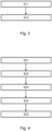
- the thermal insulation 104 is arranged around the medium pipe 102 and firmly connected to the medium pipe 102, for example welded or glued.
- the thermal insulation 104 is a foamed and hardened polyurethane foam and is used for thermal insulation of the medium to be transported in the medium pipe 102 .
- the shroud 106 is made of plastic and is placed around the thermal insulation 104 .
- the casing 106 is also firmly connected to the thermal insulation 104, for example welded or glued. The casing 106 serves to protect the thermal insulation 104.
- the medium pipe 102 is designed as a flexible, coilable and non-metallic, thermoplastic composite pipe ("thermoplastic composite pipe", TCP).
- the medium pipe 102 has an inner pipe 108, such as an inner liner, in which the medium to be transported can be guided or transported.
- the inner tube 108 is made, for example extruded, from a thermoplastic material, such as high-density polyethylene (HDPE).
- the medium pipe 102 also has a reinforcement layer 110 arranged around the inner pipe 108 .
- the reinforcement layer can comprise, for example, one or more, such as two, layers of reinforcing tape having fibers impregnated with plastic, in particular arranged unidirectionally, for example glass fibers and/or plastic fibers and/or carbon fibers and/or aramid fibers.
- the layers of reinforcing tape are spiraled in different directions around the inner tube 108 and fixedly connected thereto, such as welded or glued.
- the medium pipe 102 also has a protective jacket 112 made of plastic.
- the protective jacket 112 is arranged around the reinforcement layer 110 of the carrier pipe 102 and is firmly connected to it, such as welded or glued.
- the thermal insulation 104 is arranged around the protective jacket 112 of the medium pipe 102 and is firmly connected to the protective jacket 112, for example welded or glued.
- the conduit 100 is concentric to an axis 114, such as a longitudinal axis and/or an axis of symmetry.
- FIG. 1 schematically shows a flow chart of a method for producing the line pipe 100.
- the line pipe 100 can be configured or produced as described above and/or below.
- the medium pipe 102 is inserted into the casing 106 and/or provided with the casing 106.
- the thermal insulation is arranged in a discontinuous or continuous mode between the medium pipe 102 and the casing 106, wherein in the space between the medium pipe 102 and the casing 106 a liquid and / or foaming composition, such as Plastic composition introduced as thermal insulation, for example filled and / or injected and / or sprayed.
- the liquid or foaming composition such as a plastic composition
- the liquid or foaming composition can be designed as described above and/or below.
- at least one isocyanate component and at least one polyol can be brought together in a mixing head, which are then filled and/or injected and/or sprayed into the space between the medium pipe 102 and the casing 106 as a mixed, reactive, foaming polyurethane system.
- the then hardened plastic foam then forms the thermal insulation, which can be configured as described above and/or below.
- the medium pipe 102 can be introduced together with the casing 106 into a back conveyor and the annular gap between the medium pipe 102 and the casing 106 can be introduced with the liquid and/or foaming composition, such as a plastic composition, as thermal insulation.
- the casing 106 can be provided with the liquid and/or foaming composition, such as a plastic composition, and then inserted into the jaw belt along with the carrier tube 102 .
- FIG. 12 schematically shows a flow chart of a method for manufacturing the conduit 100 by means of a continuous process.
- the conduit 100 can be configured or manufactured as described above and/or below.
- a film such as a separating film, is formed around the at least one medium pipe 102, such as being laid and/or wrapped.
- a step S22 the thermal insulation 104 is applied and/or applied to the medium pipe 102 .
- a liquid and / or foaming Composition such as plastic composition
- the liquid and/or foaming composition such as plastic composition
- the liquid or foaming composition can be designed as described above and/or below.
- At least one isocyanate component and at least one polyol can be combined in a mixing head, which is then applied and/or applied as a mixed, reactive, foaming polyurethane system to the medium pipe 102, in particular to the outer surface of the medium pipe 102 or its protective jacket 112 is introduced into the space between the foil and the at least one medium pipe 102 .
- a step S23 the film is formed into a film tube, longitudinal edges of the film being welded and/or glued.
- the thermal insulation 104 is formed smooth or wavy, at least in its surface region, and/or the film is formed using a forming tool, such as a jaw band.
- a step S25 the casing 106 is then applied to the shaped thermal insulation 104 or to the shaped film, for example extruded, such as extruded on.
- the then hardened plastic foam then forms the thermal insulation, which can be configured as described above and/or below.
- isolated features can also be selected from the combinations of features disclosed here and used in combination with other features to delimit the subject matter of the claim, eliminating any structural and/or functional relationship that may exist between the features.
- the order and/or number of all steps of the method or methods can be varied and/or combined. The methods can be combined with one another.
Landscapes
- Engineering & Computer Science (AREA)
- General Engineering & Computer Science (AREA)
- Mechanical Engineering (AREA)
- Thermal Insulation (AREA)
- Rigid Pipes And Flexible Pipes (AREA)
Priority Applications (2)
| Application Number | Priority Date | Filing Date | Title |
|---|---|---|---|
| EP21190596.3A EP4134581B1 (fr) | 2021-08-10 | 2021-08-10 | Conduite flexible isolé et procédé de fabrication d'une telle conduite et son utilisation |
| PCT/EP2022/066983 WO2023016687A1 (fr) | 2021-08-10 | 2022-06-22 | Conduit flexible isolé thermiquement et son procédé de production |
Applications Claiming Priority (1)
| Application Number | Priority Date | Filing Date | Title |
|---|---|---|---|
| EP21190596.3A EP4134581B1 (fr) | 2021-08-10 | 2021-08-10 | Conduite flexible isolé et procédé de fabrication d'une telle conduite et son utilisation |
Publications (3)
| Publication Number | Publication Date |
|---|---|
| EP4134581A1 true EP4134581A1 (fr) | 2023-02-15 |
| EP4134581B1 EP4134581B1 (fr) | 2024-12-04 |
| EP4134581C0 EP4134581C0 (fr) | 2024-12-04 |
Family
ID=77274748
Family Applications (1)
| Application Number | Title | Priority Date | Filing Date |
|---|---|---|---|
| EP21190596.3A Active EP4134581B1 (fr) | 2021-08-10 | 2021-08-10 | Conduite flexible isolé et procédé de fabrication d'une telle conduite et son utilisation |
Country Status (2)
| Country | Link |
|---|---|
| EP (1) | EP4134581B1 (fr) |
| WO (1) | WO2023016687A1 (fr) |
Citations (4)
| Publication number | Priority date | Publication date | Assignee | Title |
|---|---|---|---|---|
| WO1995007428A1 (fr) | 1993-09-06 | 1995-03-16 | Neste Oy | Tuyau composite thermoplastique |
| WO2013079455A1 (fr) * | 2011-11-28 | 2013-06-06 | Basf Se | Procédé de fabrication de tubes extérieurs isolés dans un processus de fabrication en continu |
| WO2017048117A1 (fr) | 2015-09-14 | 2017-03-23 | Pipelife Nederland B.V. | Tuyau à haute pression et procédé de fabrication d'un tel tuyau |
| RU2630810C2 (ru) * | 2014-09-26 | 2017-09-13 | Общество с ограниченной ответственностью Научное инновационное предприятие "Дельта-Т" | Теплоизолированная гибкая полимерная труба, армированная лентами (варианты) |
Family Cites Families (9)
| Publication number | Priority date | Publication date | Assignee | Title |
|---|---|---|---|---|
| BE757688R (fr) | 1970-07-17 | 1971-04-19 | Uniroyal Inc | Tuyau integralement en matiere plastique renforce par des textiles, et procede pour sa |
| EP0375608A1 (fr) | 1988-12-11 | 1990-06-27 | "Brugg"-Kabel Ag | Conduite flexible de transport de fluides |
| CH680815A5 (en) * | 1989-06-15 | 1992-11-13 | Brugg Rohrsystem Ag | Low cost flexible conveyor pipe - has fatigue-resistant expandable metal permeation barrier fully covering inner tube |
| US20110197987A1 (en) | 2008-05-01 | 2011-08-18 | Cabot Corporation | Manufacturing and Installation of Insulated Pipes or Elements Thereof |
| US20140238977A1 (en) | 2013-02-22 | 2014-08-28 | Thercom Holdings, Llc | Composite article with induction layer and methods of forming and use thereof |
| FR3028913B1 (fr) | 2014-11-24 | 2016-12-09 | Technip France | Couche d'isolation thermique pour conduite tubulaire flexible sous-marine |
| WO2020068408A1 (fr) | 2018-09-24 | 2020-04-02 | Exxonmobil Chemical Patents Inc. | Mélanges thermoplastiques et composites pour tuyaux flexibles |
| DE202019004158U1 (de) | 2019-02-22 | 2020-02-11 | Uponor Innovation Ab | Isoliertes Rohr |
| PL3904092T3 (pl) | 2020-04-29 | 2024-10-07 | Rk Infra Gesmbh | Elastyczna wzmocniona wielowarstwowa rura polimerowa |
-
2021
- 2021-08-10 EP EP21190596.3A patent/EP4134581B1/fr active Active
-
2022
- 2022-06-22 WO PCT/EP2022/066983 patent/WO2023016687A1/fr not_active Ceased
Patent Citations (4)
| Publication number | Priority date | Publication date | Assignee | Title |
|---|---|---|---|---|
| WO1995007428A1 (fr) | 1993-09-06 | 1995-03-16 | Neste Oy | Tuyau composite thermoplastique |
| WO2013079455A1 (fr) * | 2011-11-28 | 2013-06-06 | Basf Se | Procédé de fabrication de tubes extérieurs isolés dans un processus de fabrication en continu |
| RU2630810C2 (ru) * | 2014-09-26 | 2017-09-13 | Общество с ограниченной ответственностью Научное инновационное предприятие "Дельта-Т" | Теплоизолированная гибкая полимерная труба, армированная лентами (варианты) |
| WO2017048117A1 (fr) | 2015-09-14 | 2017-03-23 | Pipelife Nederland B.V. | Tuyau à haute pression et procédé de fabrication d'un tel tuyau |
Also Published As
| Publication number | Publication date |
|---|---|
| EP4134581B1 (fr) | 2024-12-04 |
| WO2023016687A1 (fr) | 2023-02-16 |
| EP4134581C0 (fr) | 2024-12-04 |
Similar Documents
| Publication | Publication Date | Title |
|---|---|---|
| EP3112124B1 (fr) | Procede destiné a revêtir une conduite | |
| DE19629678A1 (de) | Verfahren zur Herstellung eines wärmeisolierten Leitungsrohres | |
| EP1840444B1 (fr) | Procédé pour la production d'un manteau pour conduite isolée thermiquement | |
| DE69622723T2 (de) | Rohrformiges Produkt, Extrusionsvorrichtung und Verfahren | |
| DE3018194A1 (de) | Verfahren zum herstellen von rohren, platten oder behaeltern aus kunststoff | |
| DE4128654C2 (de) | Mehrschichtiges Leitungsrohr aus Kunststoff und Verfahren zu dessen Herstellung | |
| DE3307865A1 (de) | Waermeisoliertes leitungsrohr und verfahren zu seiner herstellung | |
| EP2060843B1 (fr) | Tuyau isolé thermiquement et son procédé de fabrication | |
| AT398053B (de) | Verfahren und rohrverbindungsstück zur kontinuierlichen herstellung umschäumter, thermisch isolierter leitungsrohre | |
| EP2964996A1 (fr) | Tuyau ondulé à isolation thermique | |
| WO2021180842A1 (fr) | Tuyau souple thermoplastique, et dispositif et procédé pour produire un tel tuyau souple | |
| CH710709A1 (de) | Leitungsrohr mit thermischer Dämmung. | |
| DE4323838B4 (de) | Verfahren zur Herstellung eines mehrschichtigen Leitungsrohres | |
| DE29615423U1 (de) | Wärmeisoliertes Leitungsrohr | |
| EP4134581B1 (fr) | Conduite flexible isolé et procédé de fabrication d'une telle conduite et son utilisation | |
| DE3307120A1 (de) | Fernwaermeleitungsrohr | |
| DE3216463A1 (de) | Verfahren zum herstellen eines flexiblen fernwaermeleitungsrohres | |
| EP1628059B1 (fr) | Procédé pour fabriquer des tubes plastiques renforcés par des fibres de verre, de toutes sections et de construction sandwich | |
| EP4261012B1 (fr) | Procédé de fabrication d'un tube composite thermoplastique souple, ainsi que tube composite thermoplastique | |
| EP1055783A1 (fr) | Structure de mur à multicouche | |
| EP1640652B1 (fr) | Tuyau souple thermiquement isolé, procédé et outillage de fabrication d'un tel tuyau | |
| DE102012211651A1 (de) | Verfahren zur Herstellung eines Wickelrohrs | |
| EP0691193B1 (fr) | Procédé pour la fabrication continue d'un tube composite constitué d'un tube métallique et d'une tube intérieur en matière plastique | |
| EP2431158A1 (fr) | Procédé de fabrication de tuyaux à isolation thermique, notamment de tuyaux en cuivre | |
| DE3445282A1 (de) | Isoliertes, geschuetztes, faserverstaerktes kunststoffrohr |
Legal Events
| Date | Code | Title | Description |
|---|---|---|---|
| PUAI | Public reference made under article 153(3) epc to a published international application that has entered the european phase |
Free format text: ORIGINAL CODE: 0009012 |
|
| STAA | Information on the status of an ep patent application or granted ep patent |
Free format text: STATUS: THE APPLICATION HAS BEEN PUBLISHED |
|
| AK | Designated contracting states |
Kind code of ref document: A1 Designated state(s): AL AT BE BG CH CY CZ DE DK EE ES FI FR GB GR HR HU IE IS IT LI LT LU LV MC MK MT NL NO PL PT RO RS SE SI SK SM TR |
|
| STAA | Information on the status of an ep patent application or granted ep patent |
Free format text: STATUS: REQUEST FOR EXAMINATION WAS MADE |
|
| 17P | Request for examination filed |
Effective date: 20230801 |
|
| RBV | Designated contracting states (corrected) |
Designated state(s): AL AT BE BG CH CY CZ DE DK EE ES FI FR GB GR HR HU IE IS IT LI LT LU LV MC MK MT NL NO PL PT RO RS SE SI SK SM TR |
|
| STAA | Information on the status of an ep patent application or granted ep patent |
Free format text: STATUS: EXAMINATION IS IN PROGRESS |
|
| 17Q | First examination report despatched |
Effective date: 20240208 |
|
| RAP3 | Party data changed (applicant data changed or rights of an application transferred) |
Owner name: RK INFRA GESMBH Owner name: FIBRON PIPE GESMBH |
|
| GRAP | Despatch of communication of intention to grant a patent |
Free format text: ORIGINAL CODE: EPIDOSNIGR1 |
|
| STAA | Information on the status of an ep patent application or granted ep patent |
Free format text: STATUS: GRANT OF PATENT IS INTENDED |
|
| RIC1 | Information provided on ipc code assigned before grant |
Ipc: B29C 48/21 20190101ALI20240830BHEP Ipc: B29C 48/151 20190101ALI20240830BHEP Ipc: B29C 48/09 20190101ALI20240830BHEP Ipc: F16L 11/10 20060101ALI20240830BHEP Ipc: F16L 59/02 20060101ALI20240830BHEP Ipc: F16L 59/153 20060101ALI20240830BHEP Ipc: B29C 48/00 20190101ALI20240830BHEP Ipc: F16L 59/147 20060101AFI20240830BHEP |
|
| INTG | Intention to grant announced |
Effective date: 20240912 |
|
| GRAS | Grant fee paid |
Free format text: ORIGINAL CODE: EPIDOSNIGR3 |
|
| GRAA | (expected) grant |
Free format text: ORIGINAL CODE: 0009210 |
|
| STAA | Information on the status of an ep patent application or granted ep patent |
Free format text: STATUS: THE PATENT HAS BEEN GRANTED |
|
| AK | Designated contracting states |
Kind code of ref document: B1 Designated state(s): AL AT BE BG CH CY CZ DE DK EE ES FI FR GB GR HR HU IE IS IT LI LT LU LV MC MK MT NL NO PL PT RO RS SE SI SK SM TR |
|
| REG | Reference to a national code |
Ref country code: CH Ref legal event code: EP |
|
| REG | Reference to a national code |
Ref country code: DE Ref legal event code: R096 Ref document number: 502021005988 Country of ref document: DE |
|
| REG | Reference to a national code |
Ref country code: IE Ref legal event code: FG4D Free format text: LANGUAGE OF EP DOCUMENT: GERMAN |
|
| U01 | Request for unitary effect filed |
Effective date: 20241222 |
|
| U07 | Unitary effect registered |
Designated state(s): AT BE BG DE DK EE FI FR IT LT LU LV MT NL PT RO SE SI Effective date: 20250114 |
|
| PG25 | Lapsed in a contracting state [announced via postgrant information from national office to epo] |
Ref country code: HR Free format text: LAPSE BECAUSE OF FAILURE TO SUBMIT A TRANSLATION OF THE DESCRIPTION OR TO PAY THE FEE WITHIN THE PRESCRIBED TIME-LIMIT Effective date: 20241204 |
|
| PG25 | Lapsed in a contracting state [announced via postgrant information from national office to epo] |
Ref country code: ES Free format text: LAPSE BECAUSE OF FAILURE TO SUBMIT A TRANSLATION OF THE DESCRIPTION OR TO PAY THE FEE WITHIN THE PRESCRIBED TIME-LIMIT Effective date: 20241204 |
|
| PG25 | Lapsed in a contracting state [announced via postgrant information from national office to epo] |
Ref country code: NO Free format text: LAPSE BECAUSE OF FAILURE TO SUBMIT A TRANSLATION OF THE DESCRIPTION OR TO PAY THE FEE WITHIN THE PRESCRIBED TIME-LIMIT Effective date: 20250304 |
|
| PG25 | Lapsed in a contracting state [announced via postgrant information from national office to epo] |
Ref country code: GR Free format text: LAPSE BECAUSE OF FAILURE TO SUBMIT A TRANSLATION OF THE DESCRIPTION OR TO PAY THE FEE WITHIN THE PRESCRIBED TIME-LIMIT Effective date: 20250305 |
|
| PG25 | Lapsed in a contracting state [announced via postgrant information from national office to epo] |
Ref country code: RS Free format text: LAPSE BECAUSE OF FAILURE TO SUBMIT A TRANSLATION OF THE DESCRIPTION OR TO PAY THE FEE WITHIN THE PRESCRIBED TIME-LIMIT Effective date: 20250304 |
|
| PG25 | Lapsed in a contracting state [announced via postgrant information from national office to epo] |
Ref country code: SM Free format text: LAPSE BECAUSE OF FAILURE TO SUBMIT A TRANSLATION OF THE DESCRIPTION OR TO PAY THE FEE WITHIN THE PRESCRIBED TIME-LIMIT Effective date: 20241204 |
|
| PG25 | Lapsed in a contracting state [announced via postgrant information from national office to epo] |
Ref country code: PL Free format text: LAPSE BECAUSE OF FAILURE TO SUBMIT A TRANSLATION OF THE DESCRIPTION OR TO PAY THE FEE WITHIN THE PRESCRIBED TIME-LIMIT Effective date: 20241204 |
|
| PG25 | Lapsed in a contracting state [announced via postgrant information from national office to epo] |
Ref country code: IS Free format text: LAPSE BECAUSE OF FAILURE TO SUBMIT A TRANSLATION OF THE DESCRIPTION OR TO PAY THE FEE WITHIN THE PRESCRIBED TIME-LIMIT Effective date: 20250404 |
|
| PG25 | Lapsed in a contracting state [announced via postgrant information from national office to epo] |
Ref country code: SK Free format text: LAPSE BECAUSE OF FAILURE TO SUBMIT A TRANSLATION OF THE DESCRIPTION OR TO PAY THE FEE WITHIN THE PRESCRIBED TIME-LIMIT Effective date: 20241204 |
|
| PG25 | Lapsed in a contracting state [announced via postgrant information from national office to epo] |
Ref country code: CZ Free format text: LAPSE BECAUSE OF FAILURE TO SUBMIT A TRANSLATION OF THE DESCRIPTION OR TO PAY THE FEE WITHIN THE PRESCRIBED TIME-LIMIT Effective date: 20241204 |
|
| PLBI | Opposition filed |
Free format text: ORIGINAL CODE: 0009260 |
|
| PLAX | Notice of opposition and request to file observation + time limit sent |
Free format text: ORIGINAL CODE: EPIDOSNOBS2 |
|
| U20 | Renewal fee for the european patent with unitary effect paid |
Year of fee payment: 5 Effective date: 20250826 |
|
| 26 | Opposition filed |
Opponent name: MASTERFLEX SE Effective date: 20250904 |
|
| PLBB | Reply of patent proprietor to notice(s) of opposition received |
Free format text: ORIGINAL CODE: EPIDOSNOBS3 |
|
| REG | Reference to a national code |
Ref country code: CH Ref legal event code: H13 Free format text: ST27 STATUS EVENT CODE: U-0-0-H10-H13 (AS PROVIDED BY THE NATIONAL OFFICE) Effective date: 20260324 |
|
| PG25 | Lapsed in a contracting state [announced via postgrant information from national office to epo] |
Ref country code: MC Free format text: LAPSE BECAUSE OF FAILURE TO SUBMIT A TRANSLATION OF THE DESCRIPTION OR TO PAY THE FEE WITHIN THE PRESCRIBED TIME-LIMIT Effective date: 20241204 |
|
| PG25 | Lapsed in a contracting state [announced via postgrant information from national office to epo] |
Ref country code: CH Free format text: LAPSE BECAUSE OF NON-PAYMENT OF DUE FEES Effective date: 20250831 |
|
| PLAB | Opposition data, opponent's data or that of the opponent's representative modified |
Free format text: ORIGINAL CODE: 0009299OPPO |
|
| REG | Reference to a national code |
Ref country code: CH Ref legal event code: L10 Free format text: ST27 STATUS EVENT CODE: U-0-0-L10-L00 (AS PROVIDED BY THE NATIONAL OFFICE) Effective date: 20260430 |