EP4134589B1 - Zündbrenner für brennkammer - Google Patents
Zündbrenner für brennkammer Download PDFInfo
- Publication number
- EP4134589B1 EP4134589B1 EP22187447.2A EP22187447A EP4134589B1 EP 4134589 B1 EP4134589 B1 EP 4134589B1 EP 22187447 A EP22187447 A EP 22187447A EP 4134589 B1 EP4134589 B1 EP 4134589B1
- Authority
- EP
- European Patent Office
- Prior art keywords
- burner
- plenum
- conduit
- fuel
- pilot
- Prior art date
- Legal status (The legal status is an assumption and is not a legal conclusion. Google has not performed a legal analysis and makes no representation as to the accuracy of the status listed.)
- Active
Links
Images


Classifications
-
- F—MECHANICAL ENGINEERING; LIGHTING; HEATING; WEAPONS; BLASTING
- F23—COMBUSTION APPARATUS; COMBUSTION PROCESSES
- F23R—GENERATING COMBUSTION PRODUCTS OF HIGH PRESSURE OR HIGH VELOCITY, e.g. GAS-TURBINE COMBUSTION CHAMBERS
- F23R3/00—Continuous combustion chambers using liquid or gaseous fuel
- F23R3/02—Continuous combustion chambers using liquid or gaseous fuel characterised by the air-flow or gas-flow configuration
- F23R3/04—Air inlet arrangements
- F23R3/10—Air inlet arrangements for primary air
- F23R3/12—Air inlet arrangements for primary air inducing a vortex
- F23R3/14—Air inlet arrangements for primary air inducing a vortex by using swirl vanes
-
- F—MECHANICAL ENGINEERING; LIGHTING; HEATING; WEAPONS; BLASTING
- F23—COMBUSTION APPARATUS; COMBUSTION PROCESSES
- F23R—GENERATING COMBUSTION PRODUCTS OF HIGH PRESSURE OR HIGH VELOCITY, e.g. GAS-TURBINE COMBUSTION CHAMBERS
- F23R3/00—Continuous combustion chambers using liquid or gaseous fuel
- F23R3/28—Continuous combustion chambers using liquid or gaseous fuel characterised by the fuel supply
- F23R3/283—Attaching or cooling of fuel injecting means including supports for fuel injectors, stems, or lances
-
- F—MECHANICAL ENGINEERING; LIGHTING; HEATING; WEAPONS; BLASTING
- F23—COMBUSTION APPARATUS; COMBUSTION PROCESSES
- F23R—GENERATING COMBUSTION PRODUCTS OF HIGH PRESSURE OR HIGH VELOCITY, e.g. GAS-TURBINE COMBUSTION CHAMBERS
- F23R3/00—Continuous combustion chambers using liquid or gaseous fuel
- F23R3/28—Continuous combustion chambers using liquid or gaseous fuel characterised by the fuel supply
- F23R3/286—Continuous combustion chambers using liquid or gaseous fuel characterised by the fuel supply having fuel-air premixing devices
-
- F—MECHANICAL ENGINEERING; LIGHTING; HEATING; WEAPONS; BLASTING
- F23—COMBUSTION APPARATUS; COMBUSTION PROCESSES
- F23R—GENERATING COMBUSTION PRODUCTS OF HIGH PRESSURE OR HIGH VELOCITY, e.g. GAS-TURBINE COMBUSTION CHAMBERS
- F23R3/00—Continuous combustion chambers using liquid or gaseous fuel
- F23R3/28—Continuous combustion chambers using liquid or gaseous fuel characterised by the fuel supply
- F23R3/34—Feeding into different combustion zones
- F23R3/343—Pilot flames, i.e. fuel nozzles or injectors using only a very small proportion of the total fuel to insure continuous combustion
-
- F—MECHANICAL ENGINEERING; LIGHTING; HEATING; WEAPONS; BLASTING
- F23—COMBUSTION APPARATUS; COMBUSTION PROCESSES
- F23C—METHODS OR APPARATUS FOR COMBUSTION USING FLUID FUEL OR SOLID FUEL SUSPENDED IN A CARRIER GAS OR AIR
- F23C2900/00—Special features of, or arrangements for combustion apparatus using fluid fuels or solid fuels suspended in air; Combustion processes therefor
- F23C2900/07002—Premix burners with air inlet slots obtained between offset curved wall surfaces, e.g. double cone burners
-
- F—MECHANICAL ENGINEERING; LIGHTING; HEATING; WEAPONS; BLASTING
- F23—COMBUSTION APPARATUS; COMBUSTION PROCESSES
- F23C—METHODS OR APPARATUS FOR COMBUSTION USING FLUID FUEL OR SOLID FUEL SUSPENDED IN A CARRIER GAS OR AIR
- F23C2900/00—Special features of, or arrangements for combustion apparatus using fluid fuels or solid fuels suspended in air; Combustion processes therefor
- F23C2900/07021—Details of lances
-
- F—MECHANICAL ENGINEERING; LIGHTING; HEATING; WEAPONS; BLASTING
- F23—COMBUSTION APPARATUS; COMBUSTION PROCESSES
- F23R—GENERATING COMBUSTION PRODUCTS OF HIGH PRESSURE OR HIGH VELOCITY, e.g. GAS-TURBINE COMBUSTION CHAMBERS
- F23R2900/00—Special features of, or arrangements for continuous combustion chambers; Combustion processes therefor
- F23R2900/03343—Pilot burners operating in premixed mode
Definitions
- the disclosure relates generally to combustors and, more particularly, to a pilot burner for a combustor having a single fuel conduit and an air conduit.
- Gas turbine systems are used in a wide variety of applications to generate power.
- gas turbine system air flows through a compressor, and the compressed air is supplied to a combustion section.
- the compressed air is supplied to one or more combustors each having a number of fuel nozzles, i.e., burners, which use the air in a combustion process with a fuel.
- the compressor includes an array of inlet guide vanes (IGVs), the angle of which can be controlled to control an air flow to the combustion section, and thus a combustion temperature.
- the combustion section is in flow communication with a turbine section in which the combustion gas stream's kinetic and thermal energy is converted to mechanical rotational energy.
- the turbine section includes a turbine that rotatably couples to and drives a rotor.
- the compressor may also rotatably couple to the rotor.
- the rotor may drive a load, like an electric generator.
- the combustion section includes a number of combustors that can be used to control the load of the GT system, e.g., a plurality of circumferentially spaced combustor 'cans.
- a header (or end cover) combustion stage may be positioned at an upstream end of the combustion region of each combustor.
- the header combustion stage includes a number of fuel nozzles or burners that act to introduce fuel for combustion in a combustion chamber defined by a respective liner.
- a plurality of burners is circumferentially arranged along a combustor dome upstream of a shared combustion chamber.
- Each burner includes a premix burner and a pilot burner.
- the premix burner includes a swirler that premixes fuel and air.
- the swirler includes a plurality of swirl vanes that impart rotation to the entering air and a plurality of fuel spokes that distribute fuel in the rotating air stream. The fuel and air then mix in an annular passage, referred to as a mixing tube, within the burner before reacting within a combustion zone in the combustion chamber.
- pilot burners are used to provide better control of the combustion process, for example, to provide improved combustion stability. For example, at low operating loads, the pilot burner may be operated to create fuel-rich zones ensuring the combustion flame does not extinguish. At higher operating loads, the pilot burner's fuel-air injection may be lowered to reduce pollutants. Pilot burners may be used in a variety of alternative settings to control the combustion process, also. In some instances, a pilot burner includes a lance extending longitudinally upstream of the mixing tube to inject a mixture including two fuels and air into the mixing tube.
- the structure to provide two fuels and air in a lance is complicated by the need to cool the pilot burner to address thermal expansion and contraction.
- the pilot burner may introduce fuel and air radially near an end of the mixing tube, but this arrangement is not ideal for operational control of the combustion process.
- US2018/231254 describes a pilot burner for a combustor of a gas turbine engine.
- An aspect of the disclosure provides a burner for a combustion chamber of a combustor, the burner comprising: a swirl generator defining a first portion of a burner interior; a mixing tube downstream of the swirl generator and defining a second portion of the burner interior, the mixing tube having an outlet opening in fluid communication with the combustion chamber; and a pilot lance extending along a longitudinal axis and extending into the burner interior, the pilot lance including a pilot burner having a single fuel conduit for supplying a fuel, and an air conduit for supplying air.
- Another aspect of the disclosure includes any of the preceding aspects, and a longitudinal position of the pilot lance and the pilot burner downstream of a combustor end of the swirl generator is adjustable.
- the single fuel conduit includes an inner conduit for supplying the fuel, and the air conduit as an outer conduit concentric with the inner conduit for supplying air
- the pilot burner further includes: an inner wall defining an inner plenum; a partition wall radially outward of the inner wall and defining an intermediate plenum with at least a portion of the inner wall, the inner wall including a plurality of exit passages for fluidly coupling the inner plenum to the intermediate plenum; an outer wall defining an outer plenum with at least a portion of the partition wall; a crossover section including a first plurality of passages fluidly coupling the inner conduit to the outer plenum and a second plurality of passages fluidly coupling the outer conduit to the inner plenum; and an end plate including a plurality of openings in fluid communication with the burner interior, the plurality of openings including a set of fuel exit openings in fluid communication with the outer plenum, a set of air exit openings adjacent the set of
- Another aspect of the disclosure includes any of the preceding aspects, and further comprising a throat section in the outer plenum, the throat section constricting flow of fuel through the outer plenum.
- the throat section includes a radially outward protrusion on the partition wall and an opposing, radially inward protrusion on the outer wall, the radially outward protrusion and the radially inward protrusion defining a throat passage having a first cross-sectional area, and wherein the partition wall and the outer wall define a plenum passage upstream and downstream of the protrusions having a second cross-sectional area that is greater than the first cross-sectional area.
- Another aspect of the disclosure includes any of the preceding aspects, and the outer wall is radially flexible, and the crossover section and the end plate are less flexible than the outer wall.
- a pilot burner for a combustor comprising: an inner conduit configured to deliver a fuel; an outer conduit concentric with the inner conduit and configured to deliver air; an inner wall defining an inner plenum; a partition wall radially outward of the inner wall and defining an intermediate plenum with at least a portion of the inner wall, the inner wall including a plurality of exit passages for fluidly coupling the inner plenum to the intermedia plenum; an outer wall defining an outer plenum with at least a portion of the partition wall; a crossover section in fluid communication with the inner and outer conduit, the crossover section including a first plurality of passages fluidly coupling the inner conduit to the outer plenum and a second plurality of passages fluidly coupling the outer conduit to the inner plenum; and an end plate including a plurality of openings in fluid communication with a burner interior, the plurality of openings including a set of fuel exit openings in fluid communication with the outer
- Another aspect of the disclosure includes any of the preceding aspects, and further comprising a throat section in the outer plenum, the throat section constricting flow of fuel through the outer plenum.
- the throat section includes a radially outward protrusion on the partition wall and an opposing, radially inward protrusion on the outer wall, the radially outward protrusion and the radially inward protrusion defining a throat passage having a first cross-sectional area, and wherein the partition wall and the outer wall define a plenum passage upstream and downstream of the protrusions having a second cross-sectional area that is greater than the first cross-sectional area.
- Another aspect of the disclosure includes any of the preceding aspects, and the outer wall is radially flexible, and the crossover section and the end plate are less flexible than the outer wall.
- Another aspect of the disclosure includes any of the preceding aspects, and the inner conduit is coupled to an elongated fuel conduit of a pilot lance, and the outer conduit is coupled to elongated air conduit of the pilot lance.
- An aspect of the disclosure provides a gas turbine (GT) system, comprising: a compressor; a combustion section operatively coupled to the compressor and including an annular combustor, the annular combustor including a burner for a combustion chamber of the annular combustor, the burner including: a hood; a swirl generator operatively coupled to the hood and defining a first portion of a burner interior; a mixing tube downstream of the swirl generator and defining a second portion of the burner interior, the mixing tube having an outlet opening in fluid communication with the combustion chamber; and a pilot lance extending along a longitudinal axis and extending from the hood into the burner interior, the pilot lance including a pilot burner having a single fuel conduit for supplying a fuel, and an air conduit for supplying air; and a turbine operatively coupled to the combustion section.
- GT gas turbine
- Another aspect of the disclosure includes any of the preceding aspects, and a longitudinal position of the pilot lance and the pilot burner downstream of a combustor end of the swirl generator is adjustable.
- the single fuel conduit includes an inner conduit for supplying the fuel, and the air conduit as an outer conduit concentric with the inner conduit for supplying air
- the pilot burner further includes: an inner wall defining an inner plenum; a partition wall radially outward of the inner wall and defining an intermediate plenum with at least a portion of the inner wall, the inner wall including a plurality of exit passages for fluidly coupling the inner plenum to the intermediate plenum; an outer wall defining an outer plenum with at least a portion of the partition wall; a crossover section including a first plurality of passages fluidly coupling the inner conduit to the outer plenum and a second plurality of passages fluidly coupling the outer conduit to the inner plenum; and an end plate including a plurality of openings in fluid communication with the burner interior, the plurality of openings including a set of fuel exit openings in fluid communication with the outer plenum, a set of air exit openings adjacent the set of
- Another aspect of the disclosure includes any of the preceding aspects, and further comprising a throat section in the outer plenum, the throat section constricting flow of fuel through the outer plenum.
- the throat section includes a radially outward protrusion on the partition wall and an opposing, radially inward protrusion on the outer wall, the radially outward protrusion and the radially inward protrusion defining a throat passage having a first cross-sectional area, and wherein the partition wall and the outer wall define a plenum passage upstream and downstream of the protrusions having a second cross-sectional area that is greater than the first cross-sectional area.
- Another aspect of the disclosure includes any of the preceding aspects, and the outer wall is radially flexible, and the crossover section and the end plate are less flexible than the outer wall.
- downstream and upstream are terms that indicate a direction relative to the flow of a fluid, such as the combustion gases in a combustor, the flow of air through the combustor, or coolant through one of the turbine's component systems.
- the term “downstream” corresponds to the direction of flow of the fluid, and the term “upstream” refers to the direction opposite to the flow (i.e., the direction from which the flow originates).
- forward and aft without any further specificity, refer to directions, with “forward” referring to the front or compressor end of the engine, and “aft” referring to the rearward section of the turbomachine.
- radial refers to movement or position perpendicular to an axis. For example, if a first component resides closer to the axis than a second component, it will be stated herein that the first component is “radially inward” or “inboard” of the second component. If, on the other hand, the first component resides further from the axis than the second component, it may be stated herein that the first component is “radially outward” or “outboard” of the second component.
- axial refers to movement or position parallel to an axis.
- circumferential refers to movement or position around an axis. It will be appreciated that such terms may be applied in relation to the center axis of the turbine.
- the disclosure provides a burner and, in particular, a pilot burner for a combustor.
- the pilot burner includes an inner conduit for delivering a fuel, and an outer conduit concentric with the inner conduit for delivering air.
- An inner wall defines an inner plenum, and a partition wall radially outward of the inner wall defines an intermediate plenum with at least a portion of the inner wall.
- the inner wall includes a plurality of exit passages for fluidly coupling the inner plenum to the intermediate plenum.
- An outer wall defines an outer plenum with at least a portion of the partition wall.
- a crossover section is in fluid communication with the inner and outer conduit.
- the crossover section includes a first plurality of passages fluidly coupling the inner conduit to the outer plenum and a second plurality of passages fluidly coupling the outer conduit to the inner plenum.
- An end plate includes a plurality of openings in fluid communication with a burner interior.
- the plurality of openings includes a set of fuel exit openings in fluid communication with the outer plenum, a set of air exit openings adjacent the set of fuel exit openings and in fluid communication with the intermediate plenum, and a set of cooling openings for the end plate in fluid communication with the inner plenum.
- the pilot burner can be used with a single fuel and air and can be selectively positioned within a burner interior to provide, inter alia, improved combustion stability, quality and firing temperature control.
- FIG. 1 shows a cross-sectional view of an illustrative gas turbine system application for a burner according to embodiments of the description.
- gas turbine (GT) system 100 includes an intake section 102 and a compressor 104 downstream from intake section 102.
- Compressor 104 feeds air to a combustion section 106 that is coupled to a turbine section 120.
- Compressor 104 may include one or more stages of inlet guide vanes (IGVs) 123.
- IGVs inlet guide vanes
- Combustion section 106 includes an annular combustor 126. Exhaust from turbine section 120 exits via an exhaust section 122. Turbine section 120 drives compressor 104 and a load 124 through a common shaft or rotor connection. Load 124 may be any one of an electrical generator and a mechanical drive application and may be located forward of intake section 102 (as shown) or aft of exhaust section 122. Examples of such mechanical drive applications include an electric generator, a compressor for use in oil fields, and/or a compressor for use in refrigeration.
- the application When used in oil fields, the application may be a gas reinjection service. When used in refrigeration, the application may be in liquid natural gas (LNG) plants. Yet another load 124 may be a propeller as may be found in turbojet engines, turbofan engines and turboprop engines.
- LNG liquid natural gas
- combustion section 106 may include annular combustor 126, or a circular array of a plurality of circumferentially spaced combustors.
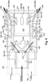
- FIG. 2 shows a partial cross-sectional side view of an illustrative annular combustor 126.
- a fuel/air mixture is burned in combustor 126 to produce the hot energetic combustion gas flow, which flows through the downstream end of combustor 126 to turbine nozzles 130 of turbine section 120 ( FIG. 1 ).
- only a portion of combustor 126 is illustrated, it being appreciated that the annular combustor 126 is symmetrical about the longitudinal axis of GT system 100. It is contemplated that the present disclosure may be used in conjunction with other combustor systems, including and not limited to can annular combustor systems.
- Combustor 126 may include a casing 132 (mounting cone), a hood 134 (or end cover) to which burners 140 are mounted, a plurality of burners 140, a front panel 142 (or cap assembly), and an outer sleeve 144 surrounding one or both of inner liner 128 and outer liner 146 of combustion plenum 162.
- An ignition device(s) (not shown) is/are provided and may include an electrically energized spark plug.
- Combustion in combustion zone 160 occurs between inner liner 128 and outer liner 146.
- Combustion air is directed within combustion plenum 162 defined by combustion liners 128, 146 via sleeve 144 and may enter combustion liner 128, 146 through burners 140 and, optionally, through a plurality of openings formed in front panel 142.
- the air enters combustion liner 128, 146 under a pressure differential and mixes with fuel from start-up burners (not shown) and/or plurality of burners 140 disposed circumferentially around front panel 142. Consequently, a combustion reaction occurs within combustion zone 160 releasing heat for the purpose of driving turbine section 120 ( FIG. 1 ).
- High-pressure air for combustion zone 160 may enter outer sleeve 144 from an annular plenum 150 defined by casing 132. Compressor 104 ( FIG. 1 ) supplies high-pressure air for this purpose and other applications relative to burners 140.
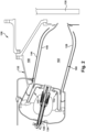
- FIG. 3 shows a cross-sectional view of a burner 140 for combustion chamber 162 of combustor 126, in accordance with embodiments of the disclosure.
- Burner 140 may be coupled to hood 134, e.g., using a mounting flange 148.
- Hood 134 and mounting flange 148 may include any structural element for mounting and/or positioning one or more burners 140.
- Mounting flange 148 may position each burner 140 for fuel and/or air supply conduit coupling, electrical connections and any other operability features, any of which may occur outside hood 134.
- Burner 140 also includes a swirl generator 156 axially spaced from and operatively coupled to hood 134.
- Swirl generator 156 defines a first portion 172 of a burner interior 174.
- Swirl generator 156 may include any now known or later developed structure for mixing an oxidizer (e.g., air) and a fuel (e.g., liquid or gaseous fuel) into a swirling gaseous flow in burner interior 174.
- swirl generator 156 may include a plurality of swirl vanes 157 that impart rotation to the entering air and a plurality of fuel spokes 158 that distribute fuel in the rotating air stream.
- IFC inlet flow conditioner
- swirl generator has a frusto-conical shape that enlarges as it progresses towards combustion chamber 162.
- Burner 140 also includes mixing tube 180 downstream of swirl generator 156, such that mixing tube 180 defines a second portion 182 of burner interior 174.
- Mixing tube 180 has an outlet opening 184 in fluid communication with combustion zone 160 of combustion chamber 162.
- Outlet opening 184 may be in, or part of, front panel 142, which may position a number of burners 140 relative to a common combustion chamber 162.
- burner 140 also includes a pilot lance 190 extending along a longitudinal axis LA of burner 140 and extending from hood 134 into burner interior 174.
- Pilot lance 190 includes a pilot burner 192 including a single fuel conduit 194 for supplying a fuel, which is surrounded by an air conduit 196 for supplying air.
- Single fuel conduit 194 of pilot burner 192 couples to an elongated fuel conduit 198 of pilot lance 190 and extending through hood 134 to couple to a fuel supply line 200.
- the fuel can be liquid, e.g., oil, or gas, e.g., natural gas.
- Air conduit 196 of pilot burner 192 couples to an elongated air conduit 202 of pilot lance 190, which extends concentrically for at least part of the length of elongated fuel conduit 198.
- Elongated air conduit 202 may include one or more inlets 204 through which high pressure air may enter.
- high-pressure air for combustion zone 160 may enter outer sleeve 144 ( FIG. 2 ) from an annular plenum 150.
- Compressor 104 FIG. 1
- the high pressure air may also be routed in a wide variety of ways from hood 134 to elongated air conduit 202.
- Pilot lance 190 includes only single fuel conduit 194, i.e., no more than one fuel is supplied by pilot lance 190.
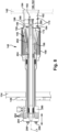
- FIGS. 5 and 6 show two cross-sectional views of pilot burner 192.
- FIG. 5 shows a cross-sectional view through: a) a plurality of passages 210 allowing crossover of fuel from an inner position to an outer position, and b) a plurality of cooling passages 212 in an end plate or heat shield 214 of pilot burner 192.
- FIG. 6 shows a cross-sectional view through: a) a plurality of passages 220 allowing crossover of air from an outer position to an inner position, and b) end plate 214 of pilot burner 192 where cooling passages 212 ( FIGS. 5 and 7 ) are not existent.
- FIGS. 5 and 7 show two cross-sectional views of pilot burner 192.
- arrows for showing the flow of fluids i.e., fuel and air
- dashed lines where the passage in which the fluid is flowing is at least partially hidden and perhaps entirely hidden
- the arrows are in solid lines where the passage is visible.
- Air is shown with thinner lined arrows
- fuel is shown with thicker lined arrows.
- single fuel conduit 194 includes an inner conduit 222 for supplying the fuel
- air conduit 196 includes an outer conduit 224 for supplying air.
- Outer conduit 224 may be concentric with inner conduit 222.
- Inner conduit 222 of pilot burner 192 is in fluid communication with elongated fuel conduit 198
- outer conduit 224 of pilot burner 192 is in fluid communication with elongated air conduit 202.
- the conduits can be physically coupled using any now known or later developed technique, e.g., welding, press fits, etc.
- Pilot burner 192 includes an inner wall 230 defining an inner plenum 232. Pilot burner 192 may also include a partition wall 234 radially outward of inner wall 230 and defining an intermediate plenum 236 with at least a portion of inner wall 230. As shown best in FIG. 6 , inner wall 230 includes a plurality of exit passages 240 for fluidly coupling inner plenum 232 to intermediate plenum 236. Any number of exit passages 240 may be provided. Pilot burner 192 also includes an outer wall 246 defining an outer plenum 248 with at least a portion of partition wall 234.
- Pilot burner 192 includes a crossover section 250 (highlighted by a box in FIGS. 5 and 6 ).
- Crossover section 250 allows transition of fuel and air in a manner to allow cooling of pilot burner 192.
- Crossover section 250 which is in fluid communication with the inner and outer conduits 222, 224, includes passages 210 fluidly coupling inner (fuel) conduit 222 to outer plenum 248 and passages 220 fluidly coupling outer (air) conduit 224 to inner plenum 232.
- plurality of passages 210 fluidly couple inner conduit 222 (for fuel) to outer plenum 248.
- Passages 210 start in fluid communication with inner conduit 222 and terminate in fluid communication with outer plenum 248. Any number of passages 210 may be used.
- crossover section 250 also includes plurality of passages 220 fluidly coupling outer conduit 224 (air) to inner plenum 232. Passages 220 start in fluid communication with outer conduit 224 and terminate in fluid communication with inner plenum 232. Any number of passages 220 may be used. Crossover section 250 also couples the various walls 230, 234, 246 to the walls of conduits 222, 224.
- Pilot burner 192 also includes an end plate 214, also sometimes referred to as a heat shield, including a plurality of openings in fluid communication with burner interior 174 ( FIG. 3 ).
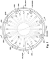
- FIG. 7 shows an end view of end plate 214. ( FIG. 7 also shows the cross-sectional view lines 5-5 and 6-6 for FIGS. 5 and 6 , respectively.)
- end plate 214 is a disc-like structure coupled to inner wall 230. End plate 214 is not coupled to partition wall 234 and outer wall 246.
- end plate 214 allows for some relative motion of inner portions (e.g., inner wall 230 and interconnected structure) relative to the stiffer outer portions (e.g., partition wall 234, outer wall 246 and interconnected structure) that direct fuel through pilot burner 192.
- inner portions e.g., inner wall 230 and interconnected structure
- stiffer outer portions e.g., partition wall 234, outer wall 246 and interconnected structure
- End plate 214 acts as a terminus of pilot burner 192.
- End plate 214 includes plurality of openings therethrough to direct the fluids (fuel and air) into combustion zone 160.
- the openings may include a set of fuel exit openings 260 in fluid communication with outer plenum 248 ( FIGS. 5 and 6 ), which holds fuel.
- the openings may also include a set of air exit openings 262 adjacent set of fuel exit openings 260 and in fluid communication with intermediate plenum 236 ( FIGS. 5 and 6 ), which holds pressurized air.
- the openings may also include a set of cooling openings 264 in fluid communication with inner plenum 232, i.e., via cooling passages 212 (shown in FIG. 5 and by dashed lines in FIG. 7 ), which holds pressurized air. In this manner, fuel exits via fuel exit openings 260 and is mixed with air exiting air exit openings 262. Air also exits cooling openings 264 passing radially through end plate 214 to cool end plate
- a set of air exit openings 262A may be adjacent fuel exit openings 260, and another set of air exit openings 262B may be radially outward of cooling openings 264.
- FIG. 7 shows how sets of air exit openings 262A, 262B may collectively form a generally circumferentially extending opening in pilot burner 192.
- the fuel and air pressures can be controlled by the sources of fuel (e.g., pump) and source of pressurized air (e.g., compressor bleed), and also by the size of openings 260, 262, 264. Any number of the openings 260, 262, 264 may be used to cool end plate 214 and create the desired fuel/air mixture for pilot combustion within mixing tube 180. In particular, any number of cooling passages 212 may be used within end plate 214.
- outer plenum 248 may also include a throat section 270 to constrict flow of fuel through outer plenum 248.
- the restriction on flow of fuel in outer plenum 248 acts to smooth flow distribution from fuel exiting passages 210 into fuel exit openings 260.
- Throat section 270 may also result in increased cooling of crossover section 250. Accordingly, the stiffness of crossover section 250 can be greater than adjacent sections because it does not experience extensive thermal expansion and contraction.
- Throat section 270 may include a radially outward protrusion 272 on partition wall 234 and an opposing, radially inward protrusion 274 on outer wall 246.
- Radially outward protrusion 272 and radially inward protrusion 274 define a throat passage 276 having a first cross-sectional area.
- partition wall 234 and outer wall 246 define a plenum passage 278 upstream and downstream of protrusions 272, 274 (that is, to both sides of protrusions 272, 274) having a second cross-sectional area that is greater than the first cross-sectional area.
- the sizing of first cross-sectional area thus creates a controllable restriction in flow of fuel through outer plenum 248 that can be employed to smooth flow distribution of air exiting passages 210 into fuel exit openings 260, and control cooling of, for example, crossover section 250.
- Pilot burner 192 may be made of any metal or metal alloy appropriate for the environmental conditions in burner 140. As noted, crossover section 250 is relatively inflexible compared to adjacent sections. More particularly, outer wall 246 may be radially flexible, whereas crossover section 250 and end plate 214 are less flexible than outer wall 246. In at least one embodiment, pilot burner 192 may be produced using additive manufacturing techniques and equipment (such as direct metal laser sintering or direct metal laser melting), which facilitates the formation of various intricate features within pilot burner 192.
- additive manufacturing techniques and equipment such as direct metal laser sintering or direct metal laser melting
- pilot lance 190 and pilot burner 192 are positioned in an operative position downstream of a combustor end 280 of swirl generator 156 in burner interior 174. That is, pilot burner 192 is downstream of swirl generator 156.
- a longitudinal position of pilot burner 192 downstream of combustor end 280 of swirl generator 156 may be adjustable. More particularly, a longitudinal position of pilot lance 190 and pilot burner 192 can be user selected.
- Pilot lance 190 is coupled near hood 134, for example, to a stationary fuel input member 290 that couples fuel supply line 200 to elongated fuel conduit 198.
- the longitudinal position of pilot lance 190 can be controlled by selecting a size and/or a number of spacer(s) 292 between a mount member 294 of pilot lance 190 and fuel input member 290 or other stationary structure near hood 134.
- spacer(s) 292 The larger the collective dimensions of spacer(s) 292, the less pilot lance 190 extends into burner interior 174.
- Spacer(s) 292 include openings (not shown) through which fasteners 296, such as bolts, can fasten mount member 294 to, for example, fuel input member 290.
- FIG. 3 shows an embodiment with no spacers 292. Consequently, pilot lance 190 is as far into burner interior 174 as possible with a given length of elongated fuel conduit 198 and elongated air conduit 202.
- FIG. 8 shows a number of spacers 292 positioning the same pilot lance 190 as in FIG. 3 farther upstream in burner interior 174. While a particular structure has been illustrated to allow different longitudinal positioning of pilot lance 190 and pilot burner 192, it will be recognized that a wide variety of alternative structures may be employed. In some instances, the extent of how far pilot burner 192 extends into burner interior 174 can be automated, e.g., using linear actuators under control of a burner controller. A length of elongated fuel conduit 198 and elongated air conduit 202 can also be user selected to control the positioning of pilot burner 192 in burner interior 174.
- embodiments of the disclosure provide a burner and a pilot burner for a combustor that uses a single fuel and air and that can be selectively positioned within a burner interior to provide, inter alia, improved combustion stability, quality and firing temperature control.
- Approximating language may be applied to modify any quantitative representation that could permissibly vary without resulting in a change in the basic function to which it is related. Accordingly, a value modified by a term or terms, such as “about,” “approximately” and “substantially,” are not to be limited to the precise value specified. In at least some instances, the approximating language may correspond to the precision of an instrument for measuring the value.
- range limitations may be combined and/or interchanged; such ranges are identified and include all the sub-ranges contained therein unless context or language indicates otherwise. "Approximately,” as applied to a particular value of a range, applies to both end values and, unless otherwise dependent on the precision of the instrument measuring the value, may indicate +/- 10% of the stated value(s).
Landscapes
- Engineering & Computer Science (AREA)
- Chemical & Material Sciences (AREA)
- Combustion & Propulsion (AREA)
- Mechanical Engineering (AREA)
- General Engineering & Computer Science (AREA)
- Pre-Mixing And Non-Premixing Gas Burner (AREA)
Claims (8)
- Zündbrenner (192) für eine Brennkammer (126), der Zündbrenner (192) umfassend:eine innere Leitung (222), die konfiguriert ist, um einen Kraftstoff zuzuführen;eine äußere Leitung (224), die konzentrisch zu der inneren Leitung (222) ist und konfiguriert ist, um Luft zuzuführen;eine Endplatte (214) einschließlich einer Vielzahl von Öffnungen (260, 262, 264) in Fluidverbindung mit einem Brennerinnenraum (174);eine innere Wand (230), die einen inneren Luftsammler (232) definiert;eine Trennwand (234), die radial außerhalb der inneren Wand (230) liegt und einen Zwischenraum (236) mit mindestens einem Abschnitt der inneren Wand (230) definiert, wobei die innere Wand (230) eine Vielzahl von Austrittskanälen (240) zum fluidischen Koppeln des inneren Luftsammlers (232) mit dem Zwischenluftsammler (236) aufweist;eine äußere Wand (246), die einen äußeren Luftsammler (248) mit mindestens einem Abschnitt der Trennwand (234) definiert;einen Überleitungsabschnitt (250) in Fluidverbindung mit der inneren und der äußeren Leitung (222, 224), wobei der Überleitungsabschnitt (250) eine erste Vielzahl von Durchgängen (210) umfasst, die die innere Leitung (222) mit dem äußeren Luftsammler (248) fluidisch verbinden, und eine zweite Vielzahl von Durchgängen (220), die die äußere Leitung (224) mit dem inneren Luftsammler (232) fluidisch verbinden; und wobeidie Vielzahl von Öffnungen (260, 262, 264) der Endplatte (214) einen Satz von Brennstoffaustrittsöffnungen (260) in Fluidverbindung mit dem äußeren Luftsammler (248), einen Satz von Luftaustrittsöffnungen (262A, 262A-B) angrenzend an den Satz von Brennstoffaustrittsöffnungen (260) und in Fluidverbindung mit dem Zwischenluftsammler (236), und einen Satz von Kühlöffnungen (264) in Fluidverbindung mit dem inneren Luftsammler (232) einschließen.
- Zündbrenner (192) nach Anspruch 1, ferner umfassend einen Verengungsabschnitt (270) in dem äußeren Luftsammler (248) , wobei der Verengungsabschnitt (270) den Brennstofffluss durch den äußeren Luftsammler (248) einschränkt.
- Zündbrenner (192) des vorstehenden Anspruchs, wobei der Verengungsabschnitt (270) einen radial nach außen gerichteten Vorsprung (272) an der Trennwand (234) und einen gegenüberliegenden radial nach innen gerichteten Vorsprung (274) an der äußeren Wand (246) umfasst, wobei der radial nach außen gerichtete Vorsprung (272) und der radial nach innen gerichtete Vorsprung (274) einen Verengungsdurchgang (276), der eine ersten Querschnittsfläche aufweist, definieren, und wobei die Trennwand (234) und die äußere Wand (246) einen Luftsammlerdurchgang (278) zu beiden Seiten der Vorsprünge (272, 274) definieren, der eine zweiten Querschnittsfläche, die größer als die erste Querschnittsfläche ist, aufweist.
- Zündbrenner (192) nach Anspruch 1, wobei die äußere Wand (246) radial flexibel ist und der Überleitungsabschnitt (250) und die Endplatte (214) weniger flexibel als die äußere Wand (246) sind.
- Zündbrenner (192) nach Anspruch 1, wobei die innere Leitung (222) mit einer verlängerten Brennstoffleitung (198) eines Zündstrahlrohrs (190) gekoppelt ist und die äußere Leitung (224) mit einer verlängerten Luftleitung (196) des Zündstrahlrohrs (190) gekoppelt ist.
- Brenner (140) für eine Verbrennungskammer (162) einer Brennkammer (126), der Brenner (140) umfassend:eine Endabdeckung (134);einen Drallgenerator (156), der mit der Endabdeckung (134) wirkgekoppelt ist und einen ersten Abschnitt (172) eines Brennerinnenraums (174) definiert;ein Mischrohr (180), das dem Drallgenerator (156) nachgelagert ist und einen zweiten Abschnitt (182) des Brennerinnenraums (174) definiert, wobei das Mischrohr (180) eine Auslassöffnung (184) aufweist, die in Fluidverbindung mit der Verbrennungskammer (162) steht; undein Zündstrahlrohr (190), das sich entlang einer Längsachse erstreckt und sich von der Endabdeckung (134) in den Brennerinnenraum (174) erstreckt, wobei das Zündstrahlrohr (190) einen Zündbrenner (192) nach einem der vorstehenden Ansprüche umfasst, wobei der Zündbrenner eine einzelne Brennstoffleitung (194) zum Zuführen eines Brennstoffs umfasst, wobei die einzelne Fluidleitung (194) die innere Leitung (222) einschließt.
- Brenner (140) nach Anspruch 6, wobei eine Längsposition der Zündstrahlrohrs (190) und des Zündbrenners (192), die einem Ende der Brennkammer (126) des Drallgenerators (156) nachgelagert sind, einstellbar ist.
- Gasturbinensystem (GT-System) (100), umfassend:einen Verdichter (104);einen Verbrennungsabschnitt (106), der mit dem Verdichter (104) wirkgekoppelt ist und eine Vielzahl von Brennkammern (126) umfasst, wobei jede Brennkammer (126) einen Brenner (140) nach einem der Ansprüche 6 oder 7 einschließt, undeine Turbine, die mit dem Verbrennungsabschnitt (106) wirkgekoppelt ist.
Applications Claiming Priority (1)
| Application Number | Priority Date | Filing Date | Title |
|---|---|---|---|
| US17/401,468 US11692711B2 (en) | 2021-08-13 | 2021-08-13 | Pilot burner for combustor |
Publications (2)
| Publication Number | Publication Date |
|---|---|
| EP4134589A1 EP4134589A1 (de) | 2023-02-15 |
| EP4134589B1 true EP4134589B1 (de) | 2025-02-26 |
Family
ID=82780783
Family Applications (1)
| Application Number | Title | Priority Date | Filing Date |
|---|---|---|---|
| EP22187447.2A Active EP4134589B1 (de) | 2021-08-13 | 2022-07-28 | Zündbrenner für brennkammer |
Country Status (3)
| Country | Link |
|---|---|
| US (1) | US11692711B2 (de) |
| EP (1) | EP4134589B1 (de) |
| CN (1) | CN115875692A (de) |
Family Cites Families (19)
| Publication number | Priority date | Publication date | Assignee | Title |
|---|---|---|---|---|
| DE10061526A1 (de) * | 2000-12-11 | 2002-06-20 | Alstom Switzerland Ltd | Vormischbrenneranordnung zum Betrieb einer Brennkammer |
| DE10205839B4 (de) * | 2002-02-13 | 2011-08-11 | Alstom Technology Ltd. | Vormischbrenner zur Verminderung verbrennungsgetriebener Schwingungen in Verbrennungssystemen |
| WO2007113130A1 (de) | 2006-03-30 | 2007-10-11 | Alstom Technology Ltd | Brenneranordnung, vorzugsweise in einer brennkammer für eine gasturbine |
| EP2179222B2 (de) * | 2007-08-07 | 2021-12-01 | Ansaldo Energia IP UK Limited | Brenner für eine brennkammer einer turbogruppe |
| EP2225488B1 (de) | 2007-11-27 | 2013-07-17 | Alstom Technology Ltd | Vormischbrenner für eine gasturbine |
| EP2110601A1 (de) | 2008-04-15 | 2009-10-21 | Siemens Aktiengesellschaft | Brenner |
| ES2576651T3 (es) * | 2009-01-15 | 2016-07-08 | Alstom Technology Ltd | Quemador de una turbina de gas |
| EP2299091A1 (de) * | 2009-09-07 | 2011-03-23 | Alstom Technology Ltd | Verfahren zum Umschalten des Betriebes eines Gasturbinenbrenners von flüssigen auf gasförmigen Brennstoff und umgekehrt. |
| EP2436979A1 (de) * | 2010-09-30 | 2012-04-04 | Siemens Aktiengesellschaft | Brenner für eine Gasturbine |
| US20130219899A1 (en) | 2012-02-27 | 2013-08-29 | General Electric Company | Annular premixed pilot in fuel nozzle |
| EP2650612A1 (de) | 2012-04-10 | 2013-10-16 | Siemens Aktiengesellschaft | Brenner |
| US10215415B2 (en) * | 2015-09-23 | 2019-02-26 | General Electric Company | Premix fuel nozzle assembly cartridge |
| US20170363294A1 (en) | 2016-06-21 | 2017-12-21 | General Electric Company | Pilot premix nozzle and fuel nozzle assembly |
| EP3361161B1 (de) | 2017-02-13 | 2023-06-07 | Ansaldo Energia Switzerland AG | Brenneranordnung für eine brennkammer eines gasturbinenkraftwerks und brennkammer mit der besagten brenneranordnung |
| EP3361159B1 (de) | 2017-02-13 | 2019-09-18 | Ansaldo Energia Switzerland AG | Verfahren zur herstellung einer brenneranordnung für eine gasturbinenbrennkammer und brenneranordnung für eine gasturbinenbrennkammer |
| US10954859B2 (en) * | 2017-07-25 | 2021-03-23 | Raytheon Technologies Corporation | Low emissions combustor assembly for gas turbine engine |
| US11371706B2 (en) * | 2017-12-18 | 2022-06-28 | General Electric Company | Premixed pilot nozzle for gas turbine combustor |
| US10890329B2 (en) | 2018-03-01 | 2021-01-12 | General Electric Company | Fuel injector assembly for gas turbine engine |
| US10907832B2 (en) * | 2018-06-08 | 2021-02-02 | General Electric Company | Pilot nozzle tips for extended lance of combustor burner |
-
2021
- 2021-08-13 US US17/401,468 patent/US11692711B2/en active Active
-
2022
- 2022-07-21 CN CN202210859059.0A patent/CN115875692A/zh active Pending
- 2022-07-28 EP EP22187447.2A patent/EP4134589B1/de active Active
Also Published As
| Publication number | Publication date |
|---|---|
| US20230046745A1 (en) | 2023-02-16 |
| CN115875692A (zh) | 2023-03-31 |
| US11692711B2 (en) | 2023-07-04 |
| EP4134589A1 (de) | 2023-02-15 |
Similar Documents
| Publication | Publication Date | Title |
|---|---|---|
| EP3845812B1 (de) | Gasturbinenverbrennungskammer mit doppeldruckvormischdüsen | |
| EP3438541B1 (de) | Gasturbine mit brennkammer und zünder | |
| CN101818907B (zh) | 用于抑制涡轮机中燃烧不稳定性的系统 | |
| EP3171088B1 (de) | Gebündelte rohrbrennstoffdüsenanordnung mit flüssigbrennstofffähigkeit | |
| US8904798B2 (en) | Combustor | |
| EP1865261A2 (de) | Einströmungskonditionierer für eine Gasturbinenbrennstoffdüse | |
| EP3220047B1 (de) | Gasturbinenstromhülsenhalterung | |
| CN101737801A (zh) | 燃气轮机中的一体化的燃烧器和一级喷嘴以及方法 | |
| US9249734B2 (en) | Combustor | |
| EP3933268B1 (de) | Anordung für eine turbomaschine umfassend eine verbrennungskammer, ein aussengehäuse und ein hochdruckplenum | |
| EP3418638B1 (de) | Brennkammer mit wärmetauscher | |
| CN115388426B (zh) | 用于燃油喷嘴的隔热罩 | |
| US20220373182A1 (en) | Pilot fuel nozzle assembly with vented venturi | |
| US10502424B2 (en) | Volute combustor for gas turbine engine | |
| CN115962486B (zh) | 燃烧器旋流器到cmc圆顶附接 | |
| US11885498B2 (en) | Turbine engine with fuel system including a catalytic reformer | |
| EP4134589B1 (de) | Zündbrenner für brennkammer | |
| EP4411232A1 (de) | Kraftstoffverteiler mit hoher scherung | |
| EP4411226A1 (de) | Zentraler luftdurchlass mit radialem kraftstoffverteiler | |
| EP2072781A2 (de) | Verfahren zur kontrollierten Spülung des Brennstoffversorgungssystems in der Brennkammer eines Gasturbinentriebwerks | |
| CN114483321B (zh) | 具有一体化头端的集成燃烧喷嘴 | |
| US20080148738A1 (en) | Combustor construction | |
| US20220364511A1 (en) | Integral fuel-nozzle and mixer with angled jet-in-crossflow fuel injection | |
| US20250257874A1 (en) | Pilot fuel nozzle assembly with multi-angled venturi | |
| GB2629432A (en) | Burner for gas turbine engine |
Legal Events
| Date | Code | Title | Description |
|---|---|---|---|
| PUAI | Public reference made under article 153(3) epc to a published international application that has entered the european phase |
Free format text: ORIGINAL CODE: 0009012 |
|
| STAA | Information on the status of an ep patent application or granted ep patent |
Free format text: STATUS: THE APPLICATION HAS BEEN PUBLISHED |
|
| AK | Designated contracting states |
Kind code of ref document: A1 Designated state(s): AL AT BE BG CH CY CZ DE DK EE ES FI FR GB GR HR HU IE IS IT LI LT LU LV MC MK MT NL NO PL PT RO RS SE SI SK SM TR |
|
| STAA | Information on the status of an ep patent application or granted ep patent |
Free format text: STATUS: REQUEST FOR EXAMINATION WAS MADE |
|
| 17P | Request for examination filed |
Effective date: 20230809 |
|
| RBV | Designated contracting states (corrected) |
Designated state(s): AL AT BE BG CH CY CZ DE DK EE ES FI FR GB GR HR HU IE IS IT LI LT LU LV MC MK MT NL NO PL PT RO RS SE SI SK SM TR |
|
| RAP1 | Party data changed (applicant data changed or rights of an application transferred) |
Owner name: GENERAL ELECTRIC TECHNOLOGY GMBH |
|
| GRAP | Despatch of communication of intention to grant a patent |
Free format text: ORIGINAL CODE: EPIDOSNIGR1 |
|
| STAA | Information on the status of an ep patent application or granted ep patent |
Free format text: STATUS: GRANT OF PATENT IS INTENDED |
|
| RIC1 | Information provided on ipc code assigned before grant |
Ipc: F23R 3/14 20060101ALI20240702BHEP Ipc: F23R 3/34 20060101ALI20240702BHEP Ipc: F23R 3/28 20060101AFI20240702BHEP |
|
| INTG | Intention to grant announced |
Effective date: 20240715 |
|
| GRAJ | Information related to disapproval of communication of intention to grant by the applicant or resumption of examination proceedings by the epo deleted |
Free format text: ORIGINAL CODE: EPIDOSDIGR1 |
|
| STAA | Information on the status of an ep patent application or granted ep patent |
Free format text: STATUS: REQUEST FOR EXAMINATION WAS MADE |
|
| GRAP | Despatch of communication of intention to grant a patent |
Free format text: ORIGINAL CODE: EPIDOSNIGR1 |
|
| STAA | Information on the status of an ep patent application or granted ep patent |
Free format text: STATUS: GRANT OF PATENT IS INTENDED |
|
| INTC | Intention to grant announced (deleted) | ||
| INTG | Intention to grant announced |
Effective date: 20241122 |
|
| GRAS | Grant fee paid |
Free format text: ORIGINAL CODE: EPIDOSNIGR3 |
|
| GRAA | (expected) grant |
Free format text: ORIGINAL CODE: 0009210 |
|
| STAA | Information on the status of an ep patent application or granted ep patent |
Free format text: STATUS: THE PATENT HAS BEEN GRANTED |
|
| AK | Designated contracting states |
Kind code of ref document: B1 Designated state(s): AL AT BE BG CH CY CZ DE DK EE ES FI FR GB GR HR HU IE IS IT LI LT LU LV MC MK MT NL NO PL PT RO RS SE SI SK SM TR |
|
| REG | Reference to a national code |
Ref country code: GB Ref legal event code: FG4D |
|
| REG | Reference to a national code |
Ref country code: CH Ref legal event code: EP |
|
| REG | Reference to a national code |
Ref country code: DE Ref legal event code: R096 Ref document number: 602022011029 Country of ref document: DE |
|
| REG | Reference to a national code |
Ref country code: IE Ref legal event code: FG4D |
|
| REG | Reference to a national code |
Ref country code: NL Ref legal event code: MP Effective date: 20250226 |
|
| PG25 | Lapsed in a contracting state [announced via postgrant information from national office to epo] |
Ref country code: RS Free format text: LAPSE BECAUSE OF FAILURE TO SUBMIT A TRANSLATION OF THE DESCRIPTION OR TO PAY THE FEE WITHIN THE PRESCRIBED TIME-LIMIT Effective date: 20250526 |
|
| PG25 | Lapsed in a contracting state [announced via postgrant information from national office to epo] |
Ref country code: FI Free format text: LAPSE BECAUSE OF FAILURE TO SUBMIT A TRANSLATION OF THE DESCRIPTION OR TO PAY THE FEE WITHIN THE PRESCRIBED TIME-LIMIT Effective date: 20250226 |
|
| PG25 | Lapsed in a contracting state [announced via postgrant information from national office to epo] |
Ref country code: PL Free format text: LAPSE BECAUSE OF FAILURE TO SUBMIT A TRANSLATION OF THE DESCRIPTION OR TO PAY THE FEE WITHIN THE PRESCRIBED TIME-LIMIT Effective date: 20250226 |
|
| PG25 | Lapsed in a contracting state [announced via postgrant information from national office to epo] |
Ref country code: ES Free format text: LAPSE BECAUSE OF FAILURE TO SUBMIT A TRANSLATION OF THE DESCRIPTION OR TO PAY THE FEE WITHIN THE PRESCRIBED TIME-LIMIT Effective date: 20250226 |
|
| REG | Reference to a national code |
Ref country code: LT Ref legal event code: MG9D |
|
| PG25 | Lapsed in a contracting state [announced via postgrant information from national office to epo] |
Ref country code: NO Free format text: LAPSE BECAUSE OF FAILURE TO SUBMIT A TRANSLATION OF THE DESCRIPTION OR TO PAY THE FEE WITHIN THE PRESCRIBED TIME-LIMIT Effective date: 20250526 Ref country code: IS Free format text: LAPSE BECAUSE OF FAILURE TO SUBMIT A TRANSLATION OF THE DESCRIPTION OR TO PAY THE FEE WITHIN THE PRESCRIBED TIME-LIMIT Effective date: 20250626 |
|
| PG25 | Lapsed in a contracting state [announced via postgrant information from national office to epo] |
Ref country code: NL Free format text: LAPSE BECAUSE OF FAILURE TO SUBMIT A TRANSLATION OF THE DESCRIPTION OR TO PAY THE FEE WITHIN THE PRESCRIBED TIME-LIMIT Effective date: 20250226 |
|
| PG25 | Lapsed in a contracting state [announced via postgrant information from national office to epo] |
Ref country code: HR Free format text: LAPSE BECAUSE OF FAILURE TO SUBMIT A TRANSLATION OF THE DESCRIPTION OR TO PAY THE FEE WITHIN THE PRESCRIBED TIME-LIMIT Effective date: 20250226 |
|
| PG25 | Lapsed in a contracting state [announced via postgrant information from national office to epo] |
Ref country code: PT Free format text: LAPSE BECAUSE OF FAILURE TO SUBMIT A TRANSLATION OF THE DESCRIPTION OR TO PAY THE FEE WITHIN THE PRESCRIBED TIME-LIMIT Effective date: 20250626 Ref country code: LV Free format text: LAPSE BECAUSE OF FAILURE TO SUBMIT A TRANSLATION OF THE DESCRIPTION OR TO PAY THE FEE WITHIN THE PRESCRIBED TIME-LIMIT Effective date: 20250226 |
|
| PG25 | Lapsed in a contracting state [announced via postgrant information from national office to epo] |
Ref country code: BG Free format text: LAPSE BECAUSE OF FAILURE TO SUBMIT A TRANSLATION OF THE DESCRIPTION OR TO PAY THE FEE WITHIN THE PRESCRIBED TIME-LIMIT Effective date: 20250226 Ref country code: GR Free format text: LAPSE BECAUSE OF FAILURE TO SUBMIT A TRANSLATION OF THE DESCRIPTION OR TO PAY THE FEE WITHIN THE PRESCRIBED TIME-LIMIT Effective date: 20250527 |
|
| REG | Reference to a national code |
Ref country code: AT Ref legal event code: MK05 Ref document number: 1770964 Country of ref document: AT Kind code of ref document: T Effective date: 20250226 |
|
| PG25 | Lapsed in a contracting state [announced via postgrant information from national office to epo] |
Ref country code: SE Free format text: LAPSE BECAUSE OF FAILURE TO SUBMIT A TRANSLATION OF THE DESCRIPTION OR TO PAY THE FEE WITHIN THE PRESCRIBED TIME-LIMIT Effective date: 20250226 |
|
| RAP4 | Party data changed (patent owner data changed or rights of a patent transferred) |
Owner name: GE VERNOVA TECHNOLOGY GMBH |
|
| PG25 | Lapsed in a contracting state [announced via postgrant information from national office to epo] |
Ref country code: SM Free format text: LAPSE BECAUSE OF FAILURE TO SUBMIT A TRANSLATION OF THE DESCRIPTION OR TO PAY THE FEE WITHIN THE PRESCRIBED TIME-LIMIT Effective date: 20250226 |
|
| PG25 | Lapsed in a contracting state [announced via postgrant information from national office to epo] |
Ref country code: DK Free format text: LAPSE BECAUSE OF FAILURE TO SUBMIT A TRANSLATION OF THE DESCRIPTION OR TO PAY THE FEE WITHIN THE PRESCRIBED TIME-LIMIT Effective date: 20250226 |
|
| PGFP | Annual fee paid to national office [announced via postgrant information from national office to epo] |
Ref country code: DE Payment date: 20250620 Year of fee payment: 4 |
|
| PGFP | Annual fee paid to national office [announced via postgrant information from national office to epo] |
Ref country code: IT Payment date: 20250731 Year of fee payment: 4 |
|
| PG25 | Lapsed in a contracting state [announced via postgrant information from national office to epo] |
Ref country code: AT Free format text: LAPSE BECAUSE OF FAILURE TO SUBMIT A TRANSLATION OF THE DESCRIPTION OR TO PAY THE FEE WITHIN THE PRESCRIBED TIME-LIMIT Effective date: 20250226 |
|
| PG25 | Lapsed in a contracting state [announced via postgrant information from national office to epo] |
Ref country code: EE Free format text: LAPSE BECAUSE OF FAILURE TO SUBMIT A TRANSLATION OF THE DESCRIPTION OR TO PAY THE FEE WITHIN THE PRESCRIBED TIME-LIMIT Effective date: 20250226 Ref country code: CZ Free format text: LAPSE BECAUSE OF FAILURE TO SUBMIT A TRANSLATION OF THE DESCRIPTION OR TO PAY THE FEE WITHIN THE PRESCRIBED TIME-LIMIT Effective date: 20250226 |
|
| PG25 | Lapsed in a contracting state [announced via postgrant information from national office to epo] |
Ref country code: RO Free format text: LAPSE BECAUSE OF FAILURE TO SUBMIT A TRANSLATION OF THE DESCRIPTION OR TO PAY THE FEE WITHIN THE PRESCRIBED TIME-LIMIT Effective date: 20250226 |
|
| PG25 | Lapsed in a contracting state [announced via postgrant information from national office to epo] |
Ref country code: SK Free format text: LAPSE BECAUSE OF FAILURE TO SUBMIT A TRANSLATION OF THE DESCRIPTION OR TO PAY THE FEE WITHIN THE PRESCRIBED TIME-LIMIT Effective date: 20250226 |
|
| REG | Reference to a national code |
Ref country code: DE Ref legal event code: R097 Ref document number: 602022011029 Country of ref document: DE |
|
| PLBE | No opposition filed within time limit |
Free format text: ORIGINAL CODE: 0009261 |
|
| STAA | Information on the status of an ep patent application or granted ep patent |
Free format text: STATUS: NO OPPOSITION FILED WITHIN TIME LIMIT |
|
| REG | Reference to a national code |
Ref country code: CH Ref legal event code: L10 Free format text: ST27 STATUS EVENT CODE: U-0-0-L10-L00 (AS PROVIDED BY THE NATIONAL OFFICE) Effective date: 20260107 |
|
| 26N | No opposition filed |
Effective date: 20251127 |
|
| REG | Reference to a national code |
Ref country code: CH Ref legal event code: H13 Free format text: ST27 STATUS EVENT CODE: U-0-0-H10-H13 (AS PROVIDED BY THE NATIONAL OFFICE) Effective date: 20260224 |
|
| PG25 | Lapsed in a contracting state [announced via postgrant information from national office to epo] |
Ref country code: LU Free format text: LAPSE BECAUSE OF NON-PAYMENT OF DUE FEES Effective date: 20250728 |
|
| REG | Reference to a national code |
Ref country code: BE Ref legal event code: MM Effective date: 20250731 |
|
| PG25 | Lapsed in a contracting state [announced via postgrant information from national office to epo] |
Ref country code: BE Free format text: LAPSE BECAUSE OF NON-PAYMENT OF DUE FEES Effective date: 20250731 |
|
| PG25 | Lapsed in a contracting state [announced via postgrant information from national office to epo] |
Ref country code: FR Free format text: LAPSE BECAUSE OF NON-PAYMENT OF DUE FEES Effective date: 20250731 |
|
| PG25 | Lapsed in a contracting state [announced via postgrant information from national office to epo] |
Ref country code: CH Free format text: LAPSE BECAUSE OF NON-PAYMENT OF DUE FEES Effective date: 20250731 |