EP4134601B1 - Kältekreislaufvorrichtung - Google Patents
Kältekreislaufvorrichtung Download PDFInfo
- Publication number
- EP4134601B1 EP4134601B1 EP20930077.1A EP20930077A EP4134601B1 EP 4134601 B1 EP4134601 B1 EP 4134601B1 EP 20930077 A EP20930077 A EP 20930077A EP 4134601 B1 EP4134601 B1 EP 4134601B1
- Authority
- EP
- European Patent Office
- Prior art keywords
- heat transfer
- heat exchanger
- flow inlet
- tube
- circumferential surface
- Prior art date
- Legal status (The legal status is an assumption and is not a legal conclusion. Google has not performed a legal analysis and makes no representation as to the accuracy of the status listed.)
- Active
Links
Images


Classifications
-
- F—MECHANICAL ENGINEERING; LIGHTING; HEATING; WEAPONS; BLASTING
- F25—REFRIGERATION OR COOLING; COMBINED HEATING AND REFRIGERATION SYSTEMS; HEAT PUMP SYSTEMS; MANUFACTURE OR STORAGE OF ICE; LIQUEFACTION SOLIDIFICATION OF GASES
- F25B—REFRIGERATION MACHINES, PLANTS OR SYSTEMS; COMBINED HEATING AND REFRIGERATION SYSTEMS; HEAT PUMP SYSTEMS
- F25B49/00—Arrangement or mounting of control or safety devices
- F25B49/02—Arrangement or mounting of control or safety devices for compression type machines, plants or systems
-
- F—MECHANICAL ENGINEERING; LIGHTING; HEATING; WEAPONS; BLASTING
- F25—REFRIGERATION OR COOLING; COMBINED HEATING AND REFRIGERATION SYSTEMS; HEAT PUMP SYSTEMS; MANUFACTURE OR STORAGE OF ICE; LIQUEFACTION SOLIDIFICATION OF GASES
- F25B—REFRIGERATION MACHINES, PLANTS OR SYSTEMS; COMBINED HEATING AND REFRIGERATION SYSTEMS; HEAT PUMP SYSTEMS
- F25B13/00—Compression machines, plants or systems, with reversible cycle
-
- F—MECHANICAL ENGINEERING; LIGHTING; HEATING; WEAPONS; BLASTING
- F25—REFRIGERATION OR COOLING; COMBINED HEATING AND REFRIGERATION SYSTEMS; HEAT PUMP SYSTEMS; MANUFACTURE OR STORAGE OF ICE; LIQUEFACTION SOLIDIFICATION OF GASES
- F25B—REFRIGERATION MACHINES, PLANTS OR SYSTEMS; COMBINED HEATING AND REFRIGERATION SYSTEMS; HEAT PUMP SYSTEMS
- F25B40/00—Subcoolers, desuperheaters or superheaters
-
- F—MECHANICAL ENGINEERING; LIGHTING; HEATING; WEAPONS; BLASTING
- F25—REFRIGERATION OR COOLING; COMBINED HEATING AND REFRIGERATION SYSTEMS; HEAT PUMP SYSTEMS; MANUFACTURE OR STORAGE OF ICE; LIQUEFACTION SOLIDIFICATION OF GASES
- F25B—REFRIGERATION MACHINES, PLANTS OR SYSTEMS; COMBINED HEATING AND REFRIGERATION SYSTEMS; HEAT PUMP SYSTEMS
- F25B41/00—Fluid-circulation arrangements
- F25B41/30—Expansion means; Dispositions thereof
- F25B41/39—Dispositions with two or more expansion means arranged in series, i.e. multi-stage expansion, on a refrigerant line leading to the same evaporator
-
- F—MECHANICAL ENGINEERING; LIGHTING; HEATING; WEAPONS; BLASTING
- F25—REFRIGERATION OR COOLING; COMBINED HEATING AND REFRIGERATION SYSTEMS; HEAT PUMP SYSTEMS; MANUFACTURE OR STORAGE OF ICE; LIQUEFACTION SOLIDIFICATION OF GASES
- F25B—REFRIGERATION MACHINES, PLANTS OR SYSTEMS; COMBINED HEATING AND REFRIGERATION SYSTEMS; HEAT PUMP SYSTEMS
- F25B2313/00—Compression machines, plants or systems with reversible cycle not otherwise provided for
- F25B2313/003—Indoor unit with water as a heat sink or heat source
-
- F—MECHANICAL ENGINEERING; LIGHTING; HEATING; WEAPONS; BLASTING
- F25—REFRIGERATION OR COOLING; COMBINED HEATING AND REFRIGERATION SYSTEMS; HEAT PUMP SYSTEMS; MANUFACTURE OR STORAGE OF ICE; LIQUEFACTION SOLIDIFICATION OF GASES
- F25B—REFRIGERATION MACHINES, PLANTS OR SYSTEMS; COMBINED HEATING AND REFRIGERATION SYSTEMS; HEAT PUMP SYSTEMS
- F25B2313/00—Compression machines, plants or systems with reversible cycle not otherwise provided for
- F25B2313/023—Compression machines, plants or systems with reversible cycle not otherwise provided for using multiple indoor units
- F25B2313/0233—Compression machines, plants or systems with reversible cycle not otherwise provided for using multiple indoor units in parallel arrangements
-
- F—MECHANICAL ENGINEERING; LIGHTING; HEATING; WEAPONS; BLASTING
- F25—REFRIGERATION OR COOLING; COMBINED HEATING AND REFRIGERATION SYSTEMS; HEAT PUMP SYSTEMS; MANUFACTURE OR STORAGE OF ICE; LIQUEFACTION SOLIDIFICATION OF GASES
- F25B—REFRIGERATION MACHINES, PLANTS OR SYSTEMS; COMBINED HEATING AND REFRIGERATION SYSTEMS; HEAT PUMP SYSTEMS
- F25B2313/00—Compression machines, plants or systems with reversible cycle not otherwise provided for
- F25B2313/029—Control issues
- F25B2313/0292—Control issues related to reversing valves
-
- F—MECHANICAL ENGINEERING; LIGHTING; HEATING; WEAPONS; BLASTING
- F25—REFRIGERATION OR COOLING; COMBINED HEATING AND REFRIGERATION SYSTEMS; HEAT PUMP SYSTEMS; MANUFACTURE OR STORAGE OF ICE; LIQUEFACTION SOLIDIFICATION OF GASES
- F25B—REFRIGERATION MACHINES, PLANTS OR SYSTEMS; COMBINED HEATING AND REFRIGERATION SYSTEMS; HEAT PUMP SYSTEMS
- F25B2313/00—Compression machines, plants or systems with reversible cycle not otherwise provided for
- F25B2313/029—Control issues
- F25B2313/0293—Control issues related to the indoor fan, e.g. controlling speed
-
- F—MECHANICAL ENGINEERING; LIGHTING; HEATING; WEAPONS; BLASTING
- F25—REFRIGERATION OR COOLING; COMBINED HEATING AND REFRIGERATION SYSTEMS; HEAT PUMP SYSTEMS; MANUFACTURE OR STORAGE OF ICE; LIQUEFACTION SOLIDIFICATION OF GASES
- F25B—REFRIGERATION MACHINES, PLANTS OR SYSTEMS; COMBINED HEATING AND REFRIGERATION SYSTEMS; HEAT PUMP SYSTEMS
- F25B2313/00—Compression machines, plants or systems with reversible cycle not otherwise provided for
- F25B2313/029—Control issues
- F25B2313/0294—Control issues related to the outdoor fan, e.g. controlling speed
-
- F—MECHANICAL ENGINEERING; LIGHTING; HEATING; WEAPONS; BLASTING
- F25—REFRIGERATION OR COOLING; COMBINED HEATING AND REFRIGERATION SYSTEMS; HEAT PUMP SYSTEMS; MANUFACTURE OR STORAGE OF ICE; LIQUEFACTION SOLIDIFICATION OF GASES
- F25B—REFRIGERATION MACHINES, PLANTS OR SYSTEMS; COMBINED HEATING AND REFRIGERATION SYSTEMS; HEAT PUMP SYSTEMS
- F25B2339/00—Details of evaporators; Details of condensers
-
- F—MECHANICAL ENGINEERING; LIGHTING; HEATING; WEAPONS; BLASTING
- F25—REFRIGERATION OR COOLING; COMBINED HEATING AND REFRIGERATION SYSTEMS; HEAT PUMP SYSTEMS; MANUFACTURE OR STORAGE OF ICE; LIQUEFACTION SOLIDIFICATION OF GASES
- F25B—REFRIGERATION MACHINES, PLANTS OR SYSTEMS; COMBINED HEATING AND REFRIGERATION SYSTEMS; HEAT PUMP SYSTEMS
- F25B2400/00—Component parts or details not otherwise provided for in this subclass
- F25B2400/12—Inflammable refrigerants
-
- F—MECHANICAL ENGINEERING; LIGHTING; HEATING; WEAPONS; BLASTING
- F25—REFRIGERATION OR COOLING; COMBINED HEATING AND REFRIGERATION SYSTEMS; HEAT PUMP SYSTEMS; MANUFACTURE OR STORAGE OF ICE; LIQUEFACTION SOLIDIFICATION OF GASES
- F25B—REFRIGERATION MACHINES, PLANTS OR SYSTEMS; COMBINED HEATING AND REFRIGERATION SYSTEMS; HEAT PUMP SYSTEMS
- F25B2400/00—Component parts or details not otherwise provided for in this subclass
- F25B2400/16—Receivers
-
- F—MECHANICAL ENGINEERING; LIGHTING; HEATING; WEAPONS; BLASTING
- F25—REFRIGERATION OR COOLING; COMBINED HEATING AND REFRIGERATION SYSTEMS; HEAT PUMP SYSTEMS; MANUFACTURE OR STORAGE OF ICE; LIQUEFACTION SOLIDIFICATION OF GASES
- F25B—REFRIGERATION MACHINES, PLANTS OR SYSTEMS; COMBINED HEATING AND REFRIGERATION SYSTEMS; HEAT PUMP SYSTEMS
- F25B2600/00—Control issues
- F25B2600/02—Compressor control
- F25B2600/025—Compressor control by controlling speed
- F25B2600/0253—Compressor control by controlling speed with variable speed
-
- F—MECHANICAL ENGINEERING; LIGHTING; HEATING; WEAPONS; BLASTING
- F25—REFRIGERATION OR COOLING; COMBINED HEATING AND REFRIGERATION SYSTEMS; HEAT PUMP SYSTEMS; MANUFACTURE OR STORAGE OF ICE; LIQUEFACTION SOLIDIFICATION OF GASES
- F25B—REFRIGERATION MACHINES, PLANTS OR SYSTEMS; COMBINED HEATING AND REFRIGERATION SYSTEMS; HEAT PUMP SYSTEMS
- F25B2600/00—Control issues
- F25B2600/11—Fan speed control
- F25B2600/111—Fan speed control of condenser fans
-
- F—MECHANICAL ENGINEERING; LIGHTING; HEATING; WEAPONS; BLASTING
- F25—REFRIGERATION OR COOLING; COMBINED HEATING AND REFRIGERATION SYSTEMS; HEAT PUMP SYSTEMS; MANUFACTURE OR STORAGE OF ICE; LIQUEFACTION SOLIDIFICATION OF GASES
- F25B—REFRIGERATION MACHINES, PLANTS OR SYSTEMS; COMBINED HEATING AND REFRIGERATION SYSTEMS; HEAT PUMP SYSTEMS
- F25B2600/00—Control issues
- F25B2600/11—Fan speed control
- F25B2600/112—Fan speed control of evaporator fans
-
- F—MECHANICAL ENGINEERING; LIGHTING; HEATING; WEAPONS; BLASTING
- F25—REFRIGERATION OR COOLING; COMBINED HEATING AND REFRIGERATION SYSTEMS; HEAT PUMP SYSTEMS; MANUFACTURE OR STORAGE OF ICE; LIQUEFACTION SOLIDIFICATION OF GASES
- F25B—REFRIGERATION MACHINES, PLANTS OR SYSTEMS; COMBINED HEATING AND REFRIGERATION SYSTEMS; HEAT PUMP SYSTEMS
- F25B2600/00—Control issues
- F25B2600/25—Control of valves
- F25B2600/2507—Flow-diverting valves
-
- F—MECHANICAL ENGINEERING; LIGHTING; HEATING; WEAPONS; BLASTING
- F25—REFRIGERATION OR COOLING; COMBINED HEATING AND REFRIGERATION SYSTEMS; HEAT PUMP SYSTEMS; MANUFACTURE OR STORAGE OF ICE; LIQUEFACTION SOLIDIFICATION OF GASES
- F25B—REFRIGERATION MACHINES, PLANTS OR SYSTEMS; COMBINED HEATING AND REFRIGERATION SYSTEMS; HEAT PUMP SYSTEMS
- F25B2600/00—Control issues
- F25B2600/25—Control of valves
- F25B2600/2513—Expansion valves
Definitions
- the present invention relates to a refrigeration cycle apparatus.
- HFO1123 is known as refrigerant having a low global warming potential (GWP) (low GWP refrigerant). Also, HFO1123 has a characteristic causing a disproportionation reaction (a self-decomposition reaction) and also has flammability.
- GWP global warming potential
- PTL 1 discloses a refrigeration cycle apparatus in which a non-azeotropic refrigerant mixture containing R32, CF3I, and HFO1123 is sealed.
- the weight ratios of R32, CF3I, and HFO1123 in the non-azeotropic refrigerant mixture sealed in the refrigeration cycle apparatus are specified.
- HFO1123 mixes with CF3I and R32, so that the disproportionation reaction of HFO1123 is suppressed, the temperature gradient of the non-azeotropic refrigerant mixture is suppressed, and performance degradation is suppressed.
- Document JP H06 281293 A discloses an outdoor heat exchanger that is formed of a tube bent continuously in an S shape and fins. Latent heat of the air to be condensed to the par to pass through the fins by a blower of an outdoor unit is derived of refrigerant gas fed in a high temperature and high pressure gas state from a compressor to become liquid state.
- the tube is reduced in its inner diameter of an inlet side and sequentially increased in its inner diameter toward an outlet side.
- the tubes molded in the same sectional area may be sequentially so increased in number of buses to two, three from the inlet side to the outlet side. Thus, cooling and heating capacities can be improved.
- JP H06 281293 A discloses a refrigeration cycle apparatus comprising: a non-azeotropic refrigerant mixture; a compressor; a flow path switching portion; a first heat exchanger having a first flow inlet/outlet portion and a second flow inlet/outlet portion through which the non-azeotropic refrigerant mixture flows in and out, and a first tube portion and a second tube portion that are connected in series to each other between the first flow inlet/outlet portion and the second flow inlet/outlet portion, the non-azeotropic refrigerant mixture flowing through the first tube portion and the second tube portion; a decompressing device; and a second heat exchanger, wherein the non-azeotropic refrigerant mixture contains refrigerant having a characteristic causing a disproportionation reaction, and refrigerant not having the characteristic causing a disproportionation reaction, the flow path switching portion performs switching between a first state in which the non-azeotropic refrigerant mixture flows in order
- Document EP 3 115 730 A1 describes a refrigeration cycle apparatus, including a load-side heat exchanger and a heat source-side heat exchanger each including tubes with inner grooves, each of the tubes having inner grooves extending obliquely with respect to a direction of a tube axis, and inner fins each being formed between the inner grooves.
- Document US 2016/341453 A1 describes a refrigeration cycle apparatus which includes a refrigeration cycle connecting a compressor, a heat source side heat exchanger, an expansion device, and a load side heat exchanger by refrigerant pipes and configured to circulate refrigerant.
- At least one of the heat source side heat exchanger and the load side heat exchanger includes one or more passages, a heat transfer enhancement mechanism (concavo-convex surface) provided to the one or more passages, and two connecting pipes serving as an inlet and an outlet for the refrigerant from and to another component in the refrigeration cycle.
- a total cross sectional area of internal cross sectional areas of the one or more passages is larger than an internal cross sectional area of at least one of the two connecting pipes.
- the relation of magnitude of the density of each of R32, CF3I, and HFO1123 varies between when R32, CF3I, and HFO1123 each are in a liquid-phase state and when R32, CF3I, and HFO1123 each are in a gas-phase state.
- the density of CF3I is higher than the density of each of R32 and HFO1123.
- the density of CF3I is lower than the density of each of R32 and HFO1123.
- CF3I is less likely to mix with R32 and HFO1123.
- CF3I is less likely to contribute to the effect of suppressing the disproportionation reaction of HFO1123, with the result that the degree of contribution of CF3I to this effect is lower than that of R32.
- a main object of the present disclosure is to provide a refrigeration cycle apparatus in which refrigerant having a characteristic causing a disproportionation reaction easily mixes with refrigerant not having the characteristic causing a disproportionation reaction, and thus, the disproportionation reaction of the refrigerant having the characteristic causing a disproportionation reaction is less likely to occur, so that performance degradation is suppressed.
- a refrigeration cycle apparatus is a refrigeration cycle apparatus comprising a non-azeotropic refrigerant mixture.
- the refrigeration cycle apparatus includes inter alia: a compressor; a flow path switching portion; a first heat exchanger having a first flow inlet/outlet portion and a second flow inlet/outlet portion through which the non-azeotropic refrigerant mixture flows in and out, and a first tube portion and a second tube portion that are connected in series to each other between the first flow inlet/outlet portion and the second flow inlet/outlet portion, the non-azeotropic refrigerant mixture flowing through the first tube portion and the second tube portion; a decompressing device; and a second heat exchanger.
- the non-azeotropic refrigerant mixture contains refrigerant having a characteristic causing a disproportionation reaction and refrigerant not having the characteristic causing a disproportionation reaction.
- the flow path switching portion performs switching between: a first state in which the non-azeotropic refrigerant mixture flows in order of the compressor, the first heat exchanger, the decompressing device, and the second heat exchanger; and a second state in which the non-azeotropic refrigerant mixture flows in a direction opposite to a direction in which the non-azeotropic refrigerant mixture flows in the first state.
- the non-azeotropic refrigerant mixture flows through the first heat exchanger in order of the first flow inlet/outlet portion, the first tube portion, the second tube portion, and the second flow inlet/outlet portion.
- the non-azeotropic refrigerant mixture flows through the first heat exchanger in order of the second flow inlet/outlet portion, the second tube portion, the first tube portion, and the first flow inlet/outlet portion.
- the first tube portion has a first inner circumferential surface provided with protrusions and recesses.
- the second tube portion has a second inner circumferential surface provided with protrusions and recesses.
- the first inner circumferential surface of the first tube portion is higher in area expansion ratio than the second inner circumferential surface of the second tube portion.
- a refrigeration cycle apparatus includes: a first refrigerant circuit through which first refrigerant circulates; a second refrigerant circuit through which second refrigerant circulates; and an intermediate heat exchanger configured to exchange heat between the first refrigerant and the second refrigerant.
- the first refrigerant circuit includes: a compressor configured to compress the first refrigerant; a flow path switching portion; a third heat exchanger configured to exchange heat between the first refrigerant and air; a decompressing device configured to decompress the first refrigerant; and a first flow path through which the first refrigerant passes in the intermediate heat exchanger.
- the second refrigerant circuit includes: a pump configured to increase pressure of the second refrigerant and convey the second refrigerant; a second flow path through which the second refrigerant passes in the intermediate heat exchanger; and a fourth heat exchanger configured to exchange heat between the second refrigerant and air.
- the first refrigerant is a non-azeotropic refrigerant mixture containing refrigerant having a characteristic causing a disproportionation reaction and refrigerant not having the characteristic causing a disproportionation reaction.
- the intermediate heat exchanger includes a fifth flow inlet/outlet portion and a sixth flow inlet/outlet portion through which the first refrigerant flows into and out of the first flow path.
- the fifth flow inlet/outlet portion is disposed above the sixth flow inlet/outlet portion.
- the flow path switching portion performs switching between: a first state in which the non-azeotropic refrigerant mixture flows in order of the compressor, the third heat exchanger, the decompressing device, and the intermediate heat exchanger; and a second state in which the non-azeotropic refrigerant mixture flows in a direction opposite to a direction in which the non-azeotropic refrigerant mixture flows in the first state.
- the first state the non-azeotropic refrigerant mixture flows through the intermediate heat exchanger from the fifth flow inlet/outlet portion toward the sixth flow inlet/outlet portion.
- the non-azeotropic refrigerant mixture flows through the intermediate heat exchanger from the sixth flow inlet/outlet portion toward the fifth flow inlet/outlet portion.
- the present invention can provide a refrigeration cycle apparatus in which refrigerant having a characteristic causing a disproportionation reaction easily mixes with refrigerant not having the characteristic causing a disproportionation reaction, and thus, the disproportionation reaction of the refrigerant having the characteristic causing a disproportionation reaction is less likely to occur, so that performance degradation is suppressed.
- a refrigeration cycle apparatus 100 is configured, for example, as a room air conditioner (RAC).
- refrigeration cycle apparatus 100 includes an outdoor unit 110 and an indoor unit 120.
- Outdoor unit 110 includes a compressor 1, a four-way valve 2 (a flow path switching portion), an outdoor heat exchanger 3 (a first heat exchanger), an expansion valve 4A (a decompressing device), an expansion valve 4B (a decompressing device), a receiver 5 (a refrigerant container), a controller 10, an outdoor fan 11, and a temperature sensor 13.
- Indoor unit 120 includes an indoor heat exchanger 6 (a second heat exchanger) and an indoor fan 12.
- the weight ratio of R32 in the non-azeotropic refrigerant mixture sealed in refrigeration cycle apparatus 100 is 43 wt% or less, for example.
- the weight ratio of CF3I in the non-azeotropic refrigerant mixture sealed in refrigeration cycle apparatus 100 is equal to or less than the weight ratio of R32, for example.
- the weight ratio of HFO1123 in the non-azeotropic refrigerant mixture sealed in refrigeration cycle apparatus 100 is 14 wt% or more, for example. From the viewpoint of suppressing the disproportionation reaction, when the weight ratio of HFO1123 is 60 wt% or more, the weight ratio of CF3I is preferably 2 wt% or more, and more preferably about 5 wt%.
- the weight ratio of IVO 1123 when the weight ratio of IVO 1123 is 60 wt% or more, the weight ratio of CF3I is 2 wt% or more and 5 wt% or less.
- the disproportionation reaction of HFO1123 is suppressed when the weight ratio of CF3I is more than 2 wt%, and the disproportionation reaction of HFO1123 is sufficiently suppressed when the weight ratio of CF3I is about 5 wt%.
- the GWP of R32 is 675
- the GWP of CF3I is about 0.4
- the GWP of HFO1123 is about 0.3.
- the GWP of the non-azeotropic refrigerant mixture is lower than the GWP of R32.
- the normal boiling points of R32, CF3I, and HFO1123 are -52°C, -22°C, and -59°C, respectively. Such a difference among the boiling points causes a concentration distribution, which will be described later, in the non-azeotropic refrigerant mixture in a gas-phase state.
- the sum of the weight ratios of HFO1123, R32, and CF3I in the non-azeotropic refrigerant mixture sealed in refrigeration cycle apparatus 100 is preferably 99.5 wt% or more, more preferably 99.7 wt% or more, and most preferably 99.9 wt% or more.
- R132 has a characteristic causing a disproportionation reaction (a self-decomposition reaction).
- incompatible oil that is incompatible with the non-azeotropic refrigerant mixture is used as lubricating oil.
- Incompatible oil includes, for example, at least one selected from the group consisting of alkylbenzene oil, mineral oil, naphthalene-based mineral oil, and polyalphaolefin oil.
- Four-way valve 2 has: a first port connected to a discharge port of compressor 1; a second port connected to a suction port of compressor 1 through receiver 5; a third port connected to an upper flow inlet/outlet portion 3A of outdoor heat exchanger 3; and a fourth port connected to an upper flow inlet/outlet portion 6A of indoor heat exchanger 6.
- Four-way valve 2 is configured to perform switching between the first state and the second state.
- outdoor heat exchanger 3 acts as a condenser and indoor heat exchanger 6 acts as an evaporator.
- indoor heat exchanger 6 acts as a condenser and outdoor heat exchanger 3 acts as an evaporator.
- the first state is implemented during a cooling operation, and the second state is implemented during a heating operation.
- outdoor heat exchanger 3 is a fin-tube heat exchanger, for example.
- Outdoor heat exchanger 3 includes: an upper flow inlet/outlet portion 3A (the first flow inlet/outlet portion) and a lower flow inlet/outlet portion 3B (the second flow inlet/outlet portion) through which a non-azeotropic refrigerant mixture flows in and out; a plurality of upper heat transfer tubes 31A (the first tube portion) and a plurality of lower heat transfer tubes 31B (the second tube portion) connected in series to each other between upper flow inlet/outlet portion 3A and lower flow inlet/outlet portion 3B; and a plurality of fins 32 each connected to upper heat transfer tubes 31A and lower heat transfer tubes 31B.
- Upper flow inlet/outlet portion 3A is disposed above lower flow inlet/outlet portion 3B. Upper flow inlet/outlet portion 3A is connected to the third port of four-way valve 2 through an extension pipe. Lower flow inlet/outlet portion 3B is connected to expansion valve 4A.
- Each of the plurality of upper heat transfer tubes 31A is disposed above each of the plurality of lower heat transfer tubes 31B.
- Each of the plurality of upper heat transfer tubes 31A is disposed above the center of outdoor heat exchanger 3, for example, in an up-down direction A.
- Each of the plurality of lower heat transfer tubes 31B is disposed below the center of outdoor heat exchanger 3, for example, in up-down direction A.
- Upper heat transfer tubes 31A and lower heat transfer tubes 31B each extend in a direction B intersecting with up-down direction A.
- One end of an upper heat transfer tube 31A in direction B that is positioned lowermost among the plurality of upper heat transfer tubes 31A is connected via a bent portion 31C in series, for example, to one end of a lower heat transfer tube 31B in direction B that is positioned uppermost among the plurality of lower heat transfer tubes 31B.
- one ends of upper heat transfer tubes 31A in direction B other than an upper heat transfer tube 31A positioned lowermost among the plurality of upper heat transfer tubes 31A are connected in series to each other via bent portion 31C.
- One ends of lower heat transfer tubes 31B in direction B other than a lower heat transfer tube 31B positioned uppermost among the plurality of lower heat transfer tubes 31B are connected in series to each other via bent portion 31C.
- upper flow inlet/outlet portion 3A, the plurality of upper heat transfer tubes 31A, the plurality of lower heat transfer tubes 31B, and lower flow inlet/outlet portion 3B are connected in series in this order.
- the plurality of fins 32 are arranged side by side at intervals in direction B.
- the plurality of upper heat transfer tubes 31A and the plurality of lower heat transfer tubes 31B penetrate through each fin 32.
- indoor heat exchanger 6 is a fin-tube heat exchanger, for example.
- Indoor heat exchanger 6 includes: an upper flow inlet/outlet portion 6A (the third flow inlet/outlet portion) and a lower flow inlet/outlet portion 6B (the fourth flow inlet/outlet portion) through which a non-azeotropic refrigerant mixture flows in and out; a plurality of upper heat transfer tubes 61A (the third tube portion) and a plurality of lower heat transfer tubes 61B (the fourth tube portion) connected in series to each other between upper flow inlet/outlet portion 6A and lower flow inlet/outlet portion 6B; and a plurality of fins 62 each connected to upper heat transfer tubes 61A and lower heat transfer tubes 61B.
- Upper flow inlet/outlet portion 6A is disposed above lower flow inlet/outlet portion 6B. Upper flow inlet/outlet portion 6A is connected to the fourth port of four-way valve 2 through an extension pipe. Lower flow inlet/outlet portion 6B is connected to expansion valve 4B through an extension pipe.
- Each of the plurality of upper heat transfer tubes 61A is disposed above each of the plurality of lower heat transfer tubes 61B.
- Each of the plurality of upper heat transfer tubes 61A is disposed above the center of indoor heat exchanger 6, for example, in up-down direction A.
- Each of the plurality of lower heat transfer tubes 61B is disposed below the center of indoor heat exchanger 6, for example, in up-down direction A.
- Upper heat transfer tubes 61A and lower heat transfer tubes 61B each extend in direction B intersecting with up-down direction A.
- One end of upper heat transfer tube 61A in direction B that is positioned lowermost among the plurality of upper heat transfer tubes 61A is connected via a bent portion 61C in series, for example, to one end of a lower heat transfer tube 61B in direction B that is positioned uppermost among the plurality of lower heat transfer tubes 61B.
- one ends of upper heat transfer tubes 61A in direction B other than an upper heat transfer tube 61A positioned lowermost among the plurality of upper heat transfer tubes 61A are connected in series to each other via bent portion 61C.
- One ends of lower heat transfer tubes 61B in direction B other than a lower heat transfer tube 61B positioned uppermost among the plurality of lower heat transfer tubes 61B are connected in series to each other via bent portion 61C.
- indoor heat exchanger 6A, the plurality of upper heat transfer tubes 61A, the plurality of lower heat transfer tubes 61B, and lower flow inlet/outlet portion 6B are connected in series in this order.
- the plurality of fins 62 are arranged side by side at intervals in direction B.
- the plurality of upper heat transfer tubes 61A and the plurality of lower heat transfer tubes 61B penetrate through each fin 62.
- upper heat transfer tubes 31A and lower heat transfer tubes 31B each are configured as a circular tube.
- each upper heat transfer tube 31A has a first inner circumferential surface 33A provided with protrusions and recesses. First inner circumferential surface 33A comes into contact with the non-azeotropic refrigerant mixture flowing through each upper heat transfer tube 31A.
- First inner circumferential surface 33A is provided with a plurality of first groove portions 34A.
- First groove portions 34A have the same configuration, for example. First groove portions 34A are spaced apart from each other in the circumferential direction of upper heat transfer tube 31A. Each first groove portion 34A extends spirally with respect to a central axis O of upper heat transfer tube 31A. Each first groove portion 34A is formed such that its width in the circumferential direction is narrower, for example, toward the outer circumference of upper heat transfer tube 31A in the radial direction.
- each lower heat transfer tube 31B has a second inner circumferential surface 33B provided with protrusions and recesses. Second inner circumferential surface 33B comes into contact with the non-azeotropic refrigerant mixture flowing through each lower heat transfer tube 31B. Second inner circumferential surface 33B is provided with a plurality of second groove portions 34B. Second groove portions 34B have the same configuration, for example. Second groove portions 34B are spaced apart from each other in the circumferential direction of lower heat transfer tube 31B. Each second groove portion 34B extends spirally with respect to a central axis O of lower heat transfer tube 31B. Each second groove portion 34B is formed such that its width in the circumferential direction is narrower, for example, toward the outer circumference of lower heat transfer tube 31B in the radial direction.
- Each upper heat transfer tube 31A is identical in outer shape, for example, to each lower heat transfer tube 31B.
- Each upper heat transfer tube 31A is equal in outer diameter, for example, to each lower heat transfer tube 31B.
- Each upper heat transfer tube 31A is equal in inner diameter, for example, to each lower heat transfer tube 31B.
- Each of the area of first inner circumferential surface 33A of each upper heat transfer tube 31A and the area of second inner circumferential surface 33B of each lower heat transfer tube 31B is larger than the area of the inner circumferential surface not provided with a groove portion though the above-mentioned inner diameter is equal to the inner diameter of each of first inner circumferential surface 33A and second inner circumferential surface 33B.
- the area expansion ratio of each of first inner circumferential surface 33A of upper heat transfer tube 31A and second inner circumferential surface 33B of lower heat transfer tube 31B is 1 or more.
- the area expansion ratio of each of first inner circumferential surface 33A and second inner circumferential surface 33B is a ratio based on the areas of the inner circumferential surfaces each not provided with a groove portion though the lengths in direction B are the same and the above-mentioned inner diameter is equal to the inner diameter of each of first inner circumferential surface 33A and second inner circumferential surface 33B.
- first inner circumferential surface 33A of upper heat transfer tube 31A (the first tube portion) is higher than the area expansion ratio of second inner circumferential surface 33B of lower heat transfer tube 31B (the second tube portion).
- the number of threads as first groove portions 34A is defined as the number of first groove portions 34A arranged side by side in the circumferential direction along a cross section perpendicular to the axial direction of upper heat transfer tube 31A.
- the number of threads as second groove portions 34B is defined as the number of second groove portions 34B arranged side by side in the circumferential direction along a cross section perpendicular to the axial direction of lower heat transfer tube 31B.
- the number of first groove portions 34A is larger than the number of second groove portions 34B.
- the width of each first groove portion 34A in the circumferential direction is smaller than the width of each second groove portion 34B in the circumferential direction.
- the relation of magnitude of the area expansion ratio between first inner circumferential surface 33A of upper heat transfer tube 31A and second inner circumferential surface 33B of lower heat transfer tube 31B is implemented by the relation of magnitude of the number of threads between first groove portions 34A and second groove portions 34B.
- each first groove portion 34A (described later in detail) is equal, for example, to the depth of each second groove portion 34B.
- the lead angle (described later in detail) of each first groove portion 34A is equal, for example, to the lead angle of each second groove portion 34B.
- the wall thickness (described later in detail) of each upper heat transfer tube 31A is equal, for example, to the wall thickness of each lower heat transfer tube 31B.
- upper heat transfer tubes 61A and lower heat transfer tubes 61B each are configured as a circular tube.
- each upper heat transfer tube 61A has a third inner circumferential surface 63A provided with protrusions and recesses. Inner circumferential surface 63A comes into contact with the non-azeotropic refrigerant mixture flowing through each upper heat transfer tube 61A.
- Third inner circumferential surface 63A is provided with a plurality of groove portions 64A. Groove portions 64A have the same configuration, for example. Groove portions 64A are spaced apart from each other in the circumferential direction of upper heat transfer tube 61A.
- Each groove portion 64A is formed spirally with respect to a central axis O of upper heat transfer tube 61A.
- Each groove portion 64A is formed such that its width in the circumferential direction is narrower, for example, toward the outer circumference of upper heat transfer tube 61A in the radial direction.
- each lower heat transfer tube 61B has a fourth inner circumferential surface 63A provided with protrusions and recesses. Fourth inner circumferential surface 63B comes into contact with the non-azeotropic refrigerant mixture flowing through each lower heat transfer tube 61B. Fourth inner circumferential surface 63B is provided with a plurality of groove portions 64B. Groove portions 64B have the same configuration, for example. Groove portions 64B are spaced apart from each other in the circumferential direction of lower heat transfer tube 61A. Each groove portion 64B is formed spirally with respect to a central axis O of lower heat transfer tube 61B. Each groove portion 64B is formed such that its width in the circumferential direction is narrower, for example, toward the outer circumference of lower heat transfer tube 61B in the radial direction.
- Each upper heat transfer tube 61A is identical in outer shape, for example, to each lower heat transfer tube 61B.
- Each upper heat transfer tube 61A is equal in outer diameter, for example, to each lower heat transfer tube 61B.
- Each upper heat transfer tube 61A is equal in inner diameter, for example, to each lower heat transfer tube 61B.
- Each of the area of third inner circumferential surface 63A of each upper heat transfer tube 61A and the area of fourth inner circumferential surface 63B of each lower heat transfer tube 61B is larger than the area of the inner circumferential surface not provided with a groove portion though the above-mentioned inner diameter is equal to the inner diameter of each of third inner circumferential surface 63A and fourth inner circumferential surface 63B.
- the area expansion ratio of each of third inner circumferential surface 63A of upper heat transfer tube 61A and fourth inner circumferential surface 63B of lower heat transfer tube 61B is 1 or more.
- the area expansion ratio of each of third inner circumferential surface 63A and fourth inner circumferential surface 63B is a ratio based on the area of the inner circumferential surface not provided with a groove portion though the above-mentioned inner diameter is equal to the inner diameter of each of third inner circumferential surface 63A and fourth inner circumferential surface 63B.
- the area expansion ratio of third inner circumferential surface 63A of upper heat transfer tube 61A (the third tube portion) is higher than the area expansion ratio of fourth inner circumferential surface 63B of lower heat transfer tube 61B (the fourth tube portion).
- the number of threads as groove portions 64A is defined as the number of groove portions 64A arranged side by side in the circumferential direction along a cross section perpendicular to the axial direction of upper heat transfer tube 61A.
- the number of threads as groove portions 64B is defined as the number of groove portions 64B arranged side by side in the circumferential direction along a cross section perpendicular to the axial direction of lower heat transfer tube 61B.
- the number of groove portions 64A is larger than the number of groove portions 64B.
- the width of each groove portion 64A in the circumferential direction is smaller than the width of each groove portion 64B in the circumferential direction.
- the relation of magnitude of the area expansion ratio between third inner circumferential surface 63A of upper heat transfer tube 61A and fourth inner circumferential surface 63B of lower heat transfer tube 61B is implemented by the relation of magnitude of the number of threads between groove portions 64A and groove portions 64B.
- each first groove portion 34A (described later in detail) is equal, for example, to the depth of each second groove portion 34B.
- the lead angle (described later in detail) of each first groove portion 34A is equal, for example, to the lead angle of each second groove portion 34B.
- the wall thickness (described later in detail) of each upper heat transfer tube 31A is equal, for example, to the wall thickness of each lower heat transfer tube 31B.
- Controller 10 controls the driving frequency of compressor 1 to thereby control the amount of refrigerant discharged from compressor 1 per unit time such that the temperature inside indoor unit 120 obtained by a temperature sensor (not shown) reaches a desired temperature (for example, the temperature set by a user). Controller 10 controls the degrees of opening of expansion valves 4A and 4B such that the degree of superheating or supercooling of the non-azeotropic refrigerant mixture attains a value in a desired range. Controller 10 controls the amount of air blown from outdoor fan 11 and indoor fan 12 per unit time. From temperature sensor 13, controller 10 obtains a discharge temperature Td of the non-azeotropic refrigerant mixture discharged from compressor 1. Controller 10 controls four-way valve 2 to switch the direction in which the non-azeotropic refrigerant mixture circulates.
- Controller 10 controls four-way valve 2 to perform switching between the cooling operation (the first state) and the heating operation (the second state).
- the non-azeotropic refrigerant mixture circulates through compressor 1, four-way valve 2, outdoor heat exchanger 3, expansion valve 4A, receiver 5, expansion valve 4B, indoor heat exchanger 6, four-way valve 2, and receiver 5 in this order.
- a part of the non-azeotropic refrigerant mixture having flowed through expansion valve 4A into receiver 5 is separated into a liquid-phase non-azeotropic refrigerant mixture and a gas-phase non-azeotropic refrigerant mixture, and then, stored in receiver 5.
- outdoor heat exchanger 3 acts as a condenser
- indoor heat exchanger 6 acts as an evaporator.
- the non-azeotropic refrigerant mixture flows through outdoor heat exchanger 3 in order of upper flow inlet/outlet portion 3A, the plurality of upper heat transfer tubes 31A, the plurality of lower heat transfer tubes 31B, and lower flow inlet/outlet portion 3B, and then, condenses.
- a gas-phase non-azeotropic refrigerant mixture mainly flows through upper flow inlet/outlet portion 3A and the plurality of upper heat transfer tubes 31A.
- a liquid-phase non-azeotropic refrigerant mixture mainly flows through the plurality of lower heat transfer tubes 31B and lower flow inlet/outlet portion 3B.
- a non-azeotropic refrigerant mixture flows through indoor heat exchanger 6 in order of lower flow inlet/outlet portion 6B, the plurality of lower heat transfer tubes 61B, the plurality of upper heat transfer tubes 61A, and upper flow inlet/outlet portion 6A, and then, evaporates.
- a non-azeotropic refrigerant mixture in a gas-liquid two-phase state mainly flows through lower flow inlet/outlet portion 6B and the plurality of lower heat transfer tubes 61B.
- a gas-phase non-azeotropic refrigerant mixture mainly flows through the plurality of upper heat transfer tubes 61A and upper flow inlet/outlet portion 6A.
- the non-azeotropic refrigerant mixture circulates through compressor 1, four-way valve 2, indoor heat exchanger 6, expansion valve 4B, receiver 5, expansion valve 4A, outdoor heat exchanger 3, four-way valve 2, and receiver 5 in this order.
- a part of the non-azeotropic refrigerant mixture having flowed from expansion valve 4B into receiver 5 is separated into a liquid-phase non-azeotropic refrigerant mixture and a gas-phase non-azeotropic refrigerant mixture, and then, stored in receiver 5.
- outdoor heat exchanger 3 acts as an evaporator and indoor heat exchanger 6 acts as a condenser.
- a non-azeotropic refrigerant mixture flows through indoor heat exchanger 6 in order of upper flow inlet/outlet portion 6A, the plurality of upper heat transfer tubes 61A, the plurality of lower heat transfer tubes 61B, and lower flow inlet/outlet portion 6B, and then, condenses.
- a gas-phase non-azeotropic refrigerant mixture mainly flows through upper flow inlet/outlet portion 6A and the plurality of upper heat transfer tubes 61A.
- a liquid-phase non-azeotropic refrigerant mixture mainly flows through the plurality of lower heat transfer tubes 61B and lower flow inlet/outlet portion 6B.
- the non-azeotropic refrigerant mixture flows through outdoor heat exchanger 3 in order of lower flow inlet/outlet portion 3B, the plurality of lower heat transfer tubes 31B, the plurality of upper heat transfer tubes 31A, and upper flow inlet/outlet portion 3A, and then, evaporates.
- a non-azeotropic refrigerant mixture in a gas-liquid two-phase state mainly flows through lower flow inlet/outlet portion 3B and the plurality of lower heat transfer tubes 31B.
- a gas-phase non-azeotropic refrigerant mixture mainly flows through the plurality of upper heat transfer tubes 31A and upper flow inlet/outlet portion 3A.
- Table 1 shows the densities of R32, CF3I, HFO1123, and alkylbenzene oil as an example of incompatible oil.
- Figs. 16 to 18 are schematic diagrams each showing the state in which the refrigerant mixture of R32, CF3I, HFO1123 and the incompatible oil flows through a circular tube extending in the horizontal direction and having a smooth inner circumferential surface.
- Fig. 16 is a schematic diagram showing the state of the refrigerant mixture in a liquid-phase state and at a temperature of 10 °C.
- Fig. 17 is a schematic diagram showing the state of the refrigerant mixture in a liquid-phase state and at a temperature of 60 °C.
- FIG. 18 is a schematic diagram showing the state of the refrigerant mixture in a gas-phase state. As shown in Table 1 and Figs. 16 to 18 , the relation of magnitude of the density of each of R32, CF3I, and IvO 1123 varies between when R32, CF3I, and HFO1123 each are in a liquid-phase state and when R32, CF3I, and HFO1123 each are in a gas-phase state.
- each refrigerant When each refrigerant is in a liquid-phase state, the relation of magnitude of the density of each refrigerant at a temperature of 10 °C is equal to the relation of magnitude of the density of each refrigerant at a temperature of 60 °C.
- the density of CF3I is higher than the density of each of R32 and HFO1123, and R32 and HFO1123 are equal in density.
- each refrigerant When each refrigerant is in a liquid-phase state, the relation of magnitude of the density between each refrigerant and the incompatible oil varies between when each refrigerant is at a temperature of 10 °C and when each refrigerant is at a temperature of 60 °C.
- the density of each refrigerant is higher than the density of the incompatible oil.
- each refrigerant When each refrigerant is in a gas-phase state, the relation of magnitude of the density of each refrigerant at a temperature of 10 °C is equal to the relation of magnitude of the density of each refrigerant at a temperature of 60 °C.
- the density of CF3I When each refrigerant is in a gas-phase state, irrespective of the temperature of each refrigerant, the density of CF3I is lower than the density of each of R32 and HFO1123, and the density of HFO1123 is higher than the density of R32.
- the non-azeotropic refrigerant mixture is hard to stir and CF3I is hard to mix with HFO1123. Accordingly, the degree of contribution of CF3I to the effect of suppressing the disproportionation reaction of HFO1123 is lower than the degree of contribution of R32 to the effect.
- upper heat transfer tube 31A and lower heat transfer tube 31B of outdoor heat exchanger 3 have first groove portions 34A and second groove portions 34B, respectively, so that the non-azeotropic refrigerant mixture is stirred more easily than in the refrigeration cycle apparatus as the above-mentioned comparative example.
- first inner circumferential surface 33A of upper heat transfer tube 31A is higher in area expansion ratio than second inner circumferential surface 33B of lower heat transfer tube 31B, and thus, the non-azeotropic refrigerant mixture is stirred more easily in upper heat transfer tube 31A than in lower heat transfer tube 31B.
- the gas-phase non-azeotropic refrigerant mixture in which R32 tends to be distributed between CF3I and HFO1123 flows through upper heat transfer tube 31A. Since the non-azeotropic refrigerant mixture flowing through upper heat transfer tube 31A is easily stirred as described above, CF3I, HFO1123, and R32 that is distributed between CF3I and HFO1123 are easily stirred, and thus, CF3I easily mixes with HFO1123. Consequently, in refrigeration cycle apparatus 100, CF3I more easily mixes with R32 and HFO1123 than in the refrigeration cycle apparatus as the above-mentioned comparative example. Accordingly, the disproportionation reaction of HFO1123 is less likely to occur, so that performance degradation is suppressed.
- upper heat transfer tube 61A and lower heat transfer tube 61B of indoor heat exchanger 6 have groove portions 64A and groove portions 64B, respectively, so that the non-azeotropic refrigerant mixture is stirred more easily than in the refrigeration cycle apparatus as the above-mentioned comparative example.
- the inner circumferential surface of upper heat transfer tube 61A is higher in area expansion ratio than the inner circumferential surface of lower heat transfer tube 61B, so that the non-azeotropic refrigerant mixture is stirred more easily in upper heat transfer tube 61A than in lower heat transfer tube 61B.
- the area expansion ratio of the inner circumferential surface of upper heat transfer tube 31A is set to be larger than the area expansion ratio of the inner circumferential surface of lower heat transfer tube 31B only by the configuration in which first groove portions 34A are larger in number than second groove portions 34B, but the present invention is not limited thereto.
- the relation of magnitude of the area expansion ratio of the inner circumferential surface between upper heat transfer tube 31A and lower heat transfer tube 31B may be achieved by the relation of magnitude of at least one of the number, the depth, and the lead angle of each first groove portion 34A and each second groove portion 34B.
- Figs. 5 and 6 each show the first modification of refrigeration cycle apparatus 100 in which the relation of magnitude of the area expansion ratio of the inner circumferential surface between upper heat transfer tube 31A and lower heat transfer tube 31B is achieved by the relation of magnitude of the depth between first groove portion 34A and second groove portion 34B.
- a depth H1 of first groove portion 34A is defined as a distance between an imaginary line L1 extending along first inner circumferential surface 33A and the inner surface of first groove portion 34A at the center of first groove portion 34A in the circumferential direction.
- First groove portions 34A have the same depth H1.
- a depth H2 of second groove portion 34B is defined as a distance between an imaginary line L2 extending along second inner circumferential surface 33B and the inner surface of second groove portion 34B at the center of second groove portion 34B in the circumferential direction. Second groove portions 34B have the same depth H2.
- depth H1 of first groove portion 34A is deeper than depth H2 of second groove portion 34B.
- first inner circumferential surface 33A of upper heat transfer tube 31A is larger in area expansion ratio than second inner circumferential surface 33B of lower heat transfer tube 31B.
- only one first groove portion 34A may be formed in upper heat transfer tube 31A, and only one second groove portion 34B may be formed in lower heat transfer tube 31B.
- Figs. 7 and 8 each show the second modification of refrigeration cycle apparatus 100 in which the relation of magnitude of the area expansion ratio of the inner circumferential surface between upper heat transfer tube 31A and lower heat transfer tube 31B is achieved by the relation of magnitude of the lead angle between first groove portion 34A and second groove portion 34B.
- a lead angle ⁇ 1 of first groove portion 34A is defined as an angle formed by the extending direction of first groove portion 34A with respect to central axis O of upper heat transfer tube 31A in a cross section along the central axis of upper heat transfer tube 31A.
- First groove portions 34A have the same lead angle ⁇ 1.
- a lead angle ⁇ 2 of second groove portion 34B is defined as an angle formed by the extending direction of second groove portion 34B with respect to central axis O of lower heat transfer tube 31B in a cross section along the central axis of lower heat transfer tube 31B.
- Second groove portions 34B have the same lead angle ⁇ 2.
- each first groove portion 34A is larger than lead angle ⁇ 2 of each second groove portion 34B.
- first inner circumferential surface 33A of upper heat transfer tube 31A is larger in area expansion ratio than second inner circumferential surface 33B of lower heat transfer tube 31B.
- only one first groove portion 34A may be formed in upper heat transfer tube 31A, and only one second groove portion 34B may be formed in lower heat transfer tube 31B.
- first groove portions 34A may be larger in number than second groove portions 34B
- lead angle ⁇ 1 of each first groove portion 34A may be larger than lead angle ⁇ 2 of each second groove portion 34B
- lead angle ⁇ 1 of each first groove portion 34A may be larger than lead angle ⁇ 2 of each second groove portion 34B.
- the relation of magnitude of the area expansion ratio of the inner circumferential surface between upper heat transfer tube 61A and lower heat transfer tube 61B may be achieved by the relation of magnitude of at least one of the number, the depth, and the lead angle of each groove portion 64A and each groove portion 64B.
- upper heat transfer tube 31A, lower heat transfer tube 31B, upper heat transfer tube 61A, and lower heat transfer tube 61B each are configured as a circular tube, but are not limited thereto. As shown in Figs. 10 to 13 , upper heat transfer tube 31A, lower heat transfer tube 31B, upper heat transfer tube 61A, and lower heat transfer tube 61B each may be configured as a flat tube. Upper heat transfer tube 31A and lower heat transfer tube 31B have the same outer shape. Upper heat transfer tube 31A has a wall thickness W, for example, equal to a wall thickness W of lower heat transfer tube 31B.
- Upper heat transfer tube 31A and lower heat transfer tube 31B each are provided with at least one of: at least one wall partitioning an inner space into a plurality of minute spaces; and at least one protrusion and recess facing the inner space.
- the area expansion ratio of each of upper heat transfer tube 31A and lower heat transfer tube 31B is defined as a ratio based on the area of the inner circumferential surface not provided with a wall and protrusions and recesses though the length in direction B and the wall thickness are equal to those of upper heat transfer tube 31A and lower heat transfer tube 31B.
- upper heat transfer tube 31A, 61A and lower heat transfer tube 31B, 61B are provided with, for example, walls 38A, walls 38B, walls 68A, and walls 68B.
- the number of walls 38A, walls 68A (in other words, the number of minute spaces) formed in upper heat transfer tube 31A, 61A is larger than, for example, the number of walls 38B, walls 68B (in other words, the number of minute spaces) formed in lower heat transfer tube 31B, 61B.
- upper heat transfer tube 31A, 61A and lower heat transfer tube 31B, 61B are provided with, for example: walls 38A, walls 38B, walls 68A, and walls 68B; and protrusions and recesses 39A, protrusions and recesses 39B, protrusions and recesses 69A, and protrusions and recesses 69B each facing the corresponding minute space partitioned by each wall.
- Each wall and each protrusion and recess extend in the direction in which each of upper heat transfer tube 31A, 61A extends.
- Protrusions and recesses 39A and protrusions and recesses 69A formed in upper heat transfer tube 31A, 61A are larger in number, for example, than protrusions and recesses 39B and protrusions and recesses 69B formed in lower heat transfer tube 31B, 61B .
- the number of walls 38A, walls 68A may be the same as or greater than the number of walls 38B, walls 68B formed in lower heat transfer tube 31B, for example.
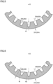
- each of outdoor heat exchanger 3 and indoor heat exchanger 6 in refrigeration cycle apparatus 100 is configured as a fin-tube heat exchanger, but is not limited thereto. As shown in Fig. 9 , outdoor heat exchanger 3 and indoor heat exchanger 6 each may be configured as a corrugated heat exchanger.
- outdoor heat exchanger 3 configured as a corrugated heat exchanger includes: an upper header 35A (the first header) connected to upper flow inlet/outlet portion 3A (the first flow inlet/outlet portion); a lower header 35B (the second header) connected to lower flow inlet/outlet portion 3B (the second flow inlet/outlet portion); a plurality of heat transfer tubes 36 connected between upper header 35A and lower header 35B and extending in up-down direction A; and a plurality of corrugated fins 37.
- Upper header 35A is disposed above lower header 35B.
- Upper header 35A is connected to each of the upper ends of the plurality of heat transfer tubes 36.
- Lower header 35B is connected to each of the lower ends of the plurality of heat transfer tubes 36.
- Upper header 35A and lower header 35B serve to distribute the non-azeotropic refrigerant mixture to the plurality of heat transfer tubes 36, or join together the non-azeotropic refrigerant mixtures having flowed through the plurality of heat transfer tubes 36.
- Upper header 35A and lower header 35B extend in direction B intersecting with up-down direction A.
- the inner circumferential surface of upper header 35A is higher in area expansion ratio than the inner circumferential surface of lower header 35B.
- indoor heat exchanger 6 configured as a corrugated heat exchanger includes: an upper header 65A (the third header) connected to upper flow inlet/outlet portion 6A (the third flow inlet/outlet portion); a lower header 65B (the fourth header) connected to lower flow inlet/outlet portion 6B (the second flow inlet/outlet portion); a plurality of heat transfer tubes 66 connected between upper header 65A and lower header 65B and extending in up-down direction A; and a plurality of corrugated fins 67.
- Upper header 65A is disposed above lower header 65B.
- Upper header 65A is connected to each of the upper ends of the plurality of heat transfer tubes 66.
- Lower header 65B is connected to each of the lower ends of the plurality of heat transfer tubes 66.
- Upper header 65A and lower header 65B serve to distribute the non-azeotropic refrigerant mixture to the plurality of heat transfer tubes 66, or join together the non-azeotropic refrigerant mixtures having flowed through the plurality of heat transfer tubes 66.
- Upper header 65A and lower header 65B extend in direction B intersecting with up-down direction A.
- Upper header 65A has an inner circumferential surface (the first inner circumferential surface) provided with protrusions and recesses.
- Lower header 65B has an inner circumferential surface (the second inner circumferential surface) provided with protrusions and recesses.
- the inner circumferential surface (the first inner circumferential surface) of upper header 65A is higher in area expansion ratio than the inner circumferential surface (the second inner circumferential surface) of lower header 65B.
- Upper header 35A and upper header 65A are similar in configuration to upper heat transfer tube 31A and upper heat transfer tube 61A, respectively, each as the first tube portion shown in Figs. 3 , 5 , and 7 .
- Lower header 35B and lower header 65B are similar in configuration to lower heat transfer tube 31B and lower heat transfer tube 61B, respectively, each as the second tube portion shown in Figs. 4 , 6 and 8 .
- one of outdoor heat exchanger 3 and indoor heat exchanger 6 may be a fin-tube heat exchanger shown in Fig. 2 while the other of outdoor heat exchanger 3 and indoor heat exchanger 6 may be a corrugated heat exchanger shown in Fig. 9 .
- outdoor heat exchanger 3 or indoor heat exchanger 6 may be configured as a conventional heat exchanger.
- the first inner circumferential surface of upper heat transfer tube 31A may be higher in area expansion ratio than the second inner circumferential surface of lower heat transfer tube 31B.
- the third inner circumferential surface of upper heat transfer tube 61A may be equal in area expansion ratio to the fourth inner circumferential surface of lower heat transfer tube 61B.
- the inner circumferential surface of upper heat transfer tube 61A may be higher in area expansion ratio than the inner circumferential surface of lower heat transfer tube 61B.
- the inner circumferential surface of upper heat transfer tube 31A may be equal in area expansion ratio to the inner circumferential surface of lower heat transfer tube 31B.
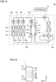
- a refrigeration cycle apparatus 100 includes: a first refrigerant circuit 130 through which first refrigerant circulates; and a second refrigerant circuit 140 through which second refrigerant circulates.
- First refrigerant circuit 130 corresponds to an "outdoor-side cycle", a "heat source-side cycle”, or a "primary circuit”.
- Second refrigerant circuit 140 corresponds to an "indoor-side cycle", a use-side cycle, or a "secondary circuit".
- First refrigerant circuit 130 includes a compressor 1, a four-way valve 2, an outdoor heat exchanger 3 (the third heat exchanger), an expansion device 4, and a first flow path H1 of an intermediate heat exchanger 7.
- the first refrigerant is a non-azeotropic refrigerant mixture with which R32, CF3I, and HFO1123 are mixed such that its GWP is reduced.
- the first refrigerant has a structure equivalent to that of the non-azeotropic refrigerant mixture in the first embodiment.
- the second refrigerant has a lower limit of flammable concentration lower than that of the first refrigerant and is, for example, CF3I single refrigerant or a refrigerant mixture such as R466A, which contains CF3I.
- Compressor 1 compresses the first refrigerant and discharges the compressed first refrigerant.
- Compressor 1 is similar in configuration to compressor 1 in the first embodiment.
- Four-way valve 2 switches the flow path of the first refrigerant.
- Four-way valve 2 has: a first port connected to the discharge port of compressor 1; a second port connected to the suction port of compressor 1; a third port connected to outdoor heat exchanger 3; and a fourth port connected to a lower flow inlet/outlet portion 7B of intermediate heat exchanger 7.
- Four-way valve 2 switches the flow path of the first refrigerant discharged from compressor 1.
- four-way valve 2 serves to form a flow path extending from compressor 1 toward outdoor heat exchanger 3.
- four-way valve 2 serves to form a flow path extending from compressor 1 toward intermediate heat exchanger 7.
- Outdoor heat exchanger 3 exchanges heat between the first refrigerant and the outdoor air.
- Expansion device 4 serves to decompress and expand the refrigerant flowing through expansion device 4 to be turned into low-temperature and low-pressure refrigerant.
- expansion device 4 for example, an electronic expansion valve can be used.
- Second refrigerant circuit 140 includes a second flow path H2 of intermediate heat exchanger 7, a pump 150, and indoor temperature control units 160, 170, and 180. Indoor temperature control units 160, 170, and 180 are connected in parallel with each other.
- Pump 150 is configured to be switchable its rotation direction between a forward direction and a backward direction.
- pump 150 switches the circulation direction of the second refrigerant so as to guide the second refrigerant in a liquid state from pump 150 to indoor heat exchangers 161, 171, and 181.
- pump 150 switches the circulation direction of the second refrigerant so as to guide the second refrigerant in a liquid state from pump 150 to second flow path H2 of intermediate heat exchanger 7.
- Indoor temperature control unit 160 includes an indoor heat exchanger 161 (the fourth heat exchanger), a fan (not shown) serving to deliver indoor air to indoor heat exchanger 161, and a flow rate control valve 162 for controlling the flow rate of the second refrigerant.
- Indoor heat exchanger 161 exchanges heat between the second refrigerant and indoor air.
- Indoor temperature control unit 170 includes an indoor heat exchanger 171, a fan (not shown) serving to deliver indoor air to indoor heat exchanger 171, and a flow rate control valve 172 for controlling the flow rate of the second refrigerant.
- Indoor heat exchanger 171 exchanges heat between the second refrigerant and indoor air.
- Indoor temperature control unit 180 includes an indoor heat exchanger 181, a fan (not shown) serving to deliver indoor air to indoor heat exchanger 181, and a flow rate control valve 182 for controlling the flow rate of the second refrigerant.
- Indoor heat exchanger 181 exchanges heat between the second refrigerant and indoor air.
- the air conditioner including three indoor temperature control units is exemplified in the present embodiment, the number of indoor temperature control units is not particularly limited.
- Fig. 15 is a schematic side view of intermediate heat exchanger 7.
- the structure shown by a broken line represents a main internal structure related to first flow path H1 in intermediate heat exchanger 7.
- intermediate heat exchanger 7 is configured as a plate heat exchanger.
- Intermediate heat exchanger 7 includes a plurality of heat transfer plates 71 stacked in direction B intersecting with up-down direction A.
- a plurality of first flow paths H1 and a plurality of second flow paths H2 are arranged in direction B alternately between the plurality of heat transfer plates 71.
- the plurality of heat transfer plates 71 are provided with: their respective upper through holes contiguous to each other in direction B and located on the relatively upper side; and their respective lower through holes contiguous to each other in direction B and disposed below the upper through holes.
- an upper distribution region 72A extending in direction B and contiguous to each first flow path H1 is provided inside the plurality of upper through holes of intermediate heat exchanger 7.
- a lower distribution region 72B extending in direction B and contiguous to each first flow path H1 is provided.
- Intermediate heat exchanger 7 exchanges heat between the first refrigerant flowing through each first flow path H1 and the second refrigerant flowing through each second flow path H2.
- Intermediate heat exchanger 7 is connected to first refrigerant circuit 130 and second refrigerant circuit 140, for example, such that first flow path H1 is opposite in flow direction to second flow path H2.
- Intermediate heat exchanger 7 further includes: an upper flow inlet/outlet portion 7A (the fifth flow inlet/outlet portion) and a lower flow inlet/outlet portion 7B (the sixth flow inlet/outlet portion) through which the first refrigerant flows into and out of first flow path H1; and an upper flow inlet/outlet portion 7C and a lower flow inlet/outlet portion 7D through which the second refrigerant flows into and out of second flow path H2.
- Upper flow inlet/outlet portion 7A is disposed above lower flow inlet/outlet portion 7B.
- Upper flow inlet/outlet portion 7A is contiguous to upper distribution region 72A in direction B.
- Lower flow inlet/outlet portion 7B is contiguous to lower distribution region 72B in direction B.
- Upper flow inlet/outlet portion 7C is disposed above lower flow inlet/outlet portion 7D.
- Upper flow inlet/outlet portion 7A is connected to expansion device 4.
- Lower flow inlet/outlet portion 7B is connected to the fourth port of four-way valve 2.
- Upper flow inlet/outlet portion 7C is connected to pump 150.
- Lower flow inlet/outlet portion 7D is connected to indoor heat exchangers 161, 171, and 181.
- the first refrigerant circulating through first refrigerant circuit 130 cools the second refrigerant circulating through second refrigerant circuit 140.
- the first refrigerant circulating through first refrigerant circuit 130 heats the second refrigerant circulating through second refrigerant circuit 140.
- the first refrigerant in the gas-liquid two-phase state of a relatively low temperature evaporates and turns into gas-phase refrigerant while flowing downward through first flow path H1 in intermediate heat exchanger 7.
- the first refrigerant in the gas-phase state condenses and turns into liquid-phase refrigerant while flowing upward through first flow path H1 in intermediate heat exchanger 7.
- Controller 10 controls the overall operation of refrigeration cycle apparatus 101. According to the outputs from the pressure sensor, the temperature sensor, and the like, controller 10 controls the rotation speeds of compressor 1, expansion device 4, pump 150, flow rate control valves 152, 172, and 182, and fans (not shown) attached to heat exchangers 3, 161, 171, and 181.
- Controller 10 causes four-way valve 2 to switch the circulation direction of the first refrigerant in first refrigerant circuit 130 between the cooling operation and the heating operation. In a manner responding to this switching operation, controller 10 changes the rotation direction of pump 150 in second refrigerant circuit 140 such that the second refrigerant flows in the direction opposite to the flow direction of the first refrigerant in intermediate heat exchanger 7 and thus exchanges heat with the first refrigerant, to thereby bring about a supercooled state at the suction port of pump 150.
- the refrigeration cycle apparatus as a comparative example including the intermediate heat exchanger in which the first refrigerant in the gas-liquid two-phase state of a relatively low temperature flows upward during the cooling operation
- R32, CF3I, HFO1123, and incompatible oil tend to be distributed as shown in Fig. 16 while CF3I tends to be distributed below R32 and HFO1123.
- the ease of flow (fluidity) of CF3I is hindered by a plate portion located below the lower through hole in each heat transfer plate.
- R32, CF3I, HFO1123, and incompatible oil tend to be distributed as shown in Fig. 18 while CF3I tends to be distributed above R32 and HFO1123.
- the fluidity of CF3I is hindered by a plate portion located above the upper through hole in each heat transfer plate.
- the first refrigerant in the gas-liquid two-phase state of a relatively low temperature flows through intermediate heat exchanger 7 in order of upper flow inlet/outlet portion 7A, upper distribution region 72A, each first flow path H1, lower distribution region 72B, and lower flow inlet/outlet portion 7B.
- R32, CF3I, HFO1123, and incompatible oil tend to be distributed as shown in Fig. 16 .
- CF3I tends to be distributed below R32 and HFO1123 in upper distribution region 72A.
- R32, CF3I, HFO1123, and incompatible oil tend to be distributed as shown in Fig. 18 .
- CF3I tends to be distributed above R32 and HFO1123 in lower distribution region 72B.
- the first refrigerant in the gas-phase state of a relatively high temperature flows through intermediate heat exchanger 7 in order of lower flow inlet/outlet portion 7B, lower distribution region 72B, each first flow path H1, upper distribution region 72A, and upper flow inlet/outlet portion 7A.
- R32, CF3I, HFO1123, and incompatible oil tend to be distributed as shown in Fig. 18 .
- CF3I tends to be distributed above R32 and HFO1123 in lower distribution region 72B.
- R32, CF3I, HFO1123, and incompatible oil tend to be distributed as shown in Fig. 17 .
- CF3I tends to be distributed below R32 and HFO1123 in upper distribution region 72A.
- the fluidity of CF3I in the first refrigerant in intermediate heat exchanger 7 is higher than that in the refrigeration cycle apparatus according to the comparative example. Since the fluidity of CF3I in intermediate heat exchanger 7 is relatively high, CF3I easily mixes with HFO1123, so that the disproportionation reaction of HFO1123 is less likely to occur, and thus, performance degradation is suppressed.
- the fluidity of CF3I in upper distribution region 72A disposed upstream of each first flow path H1 is relatively high during the cooling operation, and the fluidity of CF3I in lower distribution region 72B disposed upstream of each first flow path H1 is relatively high during the heating operation.
- the flow rate of CF3I flowing through each first flow path H1 is less variable than that in the refrigeration cycle apparatus according to the comparative example.
- Refrigeration cycle apparatuses 100 and 101 each are not limited to an RAC.
- the usage and capability of each of refrigeration cycle apparatuses 100, 101 may be arbitrarily set.
Landscapes
- Engineering & Computer Science (AREA)
- Physics & Mathematics (AREA)
- Mechanical Engineering (AREA)
- Thermal Sciences (AREA)
- General Engineering & Computer Science (AREA)
- Compression-Type Refrigeration Machines With Reversible Cycles (AREA)
- Heat-Exchange Devices With Radiators And Conduit Assemblies (AREA)
Claims (7)
- Kältekreislaufvorrichtung (100), umfassend:ein nichtazeotropes Kältemittelgemisch;einen Verdichter (1);einen Strömungspfad-Schaltabschnitt (2);einen ersten Wärmetauscher (3), aufweisend:einen ersten Einlass-/Auslassabschnitt (3A) und einen zweiten Einlass-/Auslassabschnitt (3B), durch die das nichtazeotrope Kältemittelgemisch ein- und ausströmt, undeinen ersten Leitungsabschnitt (31A) und einen zweiten Leitungsabschnitt (31B), die zwischen dem ersten Strömungseinlass-/Auslassabschnitt (3A) und dem zweiten Strömungseinlass-/Auslassabschnitt (3B) in Reihe miteinander verbunden sind, wobei das nichtazeotrope Kältemittelgemisch durch den ersten Leitungsabschnitt (31A) und den zweiten Leitungsabschnitt (31B) strömt;eine Entspannungseinrichtung (4A, 4B); undeinen zweiten Wärmetauscher (6), wobeidas nichtazeotrope Kältemittelgemisch enthält:ein Kältemittel mit einer Eigenschaft, die eine Disproportionierungsreaktion hervorruft, undein Kältemittel mit keiner Eigenschaft, die eine Disproportionierungsreaktion hervorruft,wobei der Strömungspfad-Schaltabschnitt (2) eingerichtet ist, Schalten durchzuführen zwischeneinem ersten Zustand, in dem das nichtazeotrope Kältemittelgemisch in Reihendfolge durch den Verdichter (1), den ersten Wärmetauscher (3), die Entspannungseinrichtung (4A, 4B) und den zweiten Wärmetauscher (6) strömt, undeinem zweiten Zustand, in dem das nichtazeotrope Kältemittelgemisch in eine Richtung strömt, die einer Richtung entgegengesetzt ist, in der das nichtazeotrope Kältemittelgemisch in dem ersten Zustand strömt,in dem ersten Zustand, das nichtazeotrope Kältemittelgemisch durch den ersten Wärmetauscher (3) in Reihenfolge durch den ersten Einlass-/Auslassabschnitt (3A), den ersten Leitungsabschnitt (31A), den zweiten Leitungsabschnitt (31B) und den zweiten Einlass-/Auslassabschnitt (3B),in dem zweiten Zustand, das nichtazeotrope Kältemittelgemisch durch den ersten Wärmetauscher (3) in Reihenfolge durch den zweiten Strömungseinlass-/Auslassabschnitt (3B), den zweiten Leitungsabschnitt (31B), den ersten Leitungsabschnitt (31A) und den ersten Strömungseinlass-/Auslassabschnitt (3A),der erste Leitungsabschnitt (31A) eine erste innere Umfangsoberfläche (33A) aufweist, die mit Vorsprüngen und Vertiefungen versehen ist,der zweite Leitungsabschnitt (31B) eine zweite innere Umfangsoberfläche (33B) aufweist, die mit Vorsprüngen und Vertiefungen versehen ist,die erste innere Umfangsoberfläche (33A) des ersten Leitungsabschnitts (31A) ein höheres Flächenausdehnungsverhältnis aufweist als die zweite innere Umfangsoberfläche (33B) des zweiten Leitungsabschnitts (31B),die erste innere Umfangsoberfläche (33A) mit mindestens einem ersten Rillenabschnitt (34A) versehen ist, der sich spiralförmig erstreckt,die zweite innere Umfangsoberfläche (33B) mit mindestens einem zweiten Rillenabschnitt (34B) versehen ist, der sich spiralförmig erstreckt, undin Bezug auf zumindest eines von einer Anzahl, einer Tiefe und einem Steigungswinkel jedes von dem zumindest einen ersten Rillenabschnitts (34A) und dem zumindest einen zweiten Rillenabschnitt (34B), der zumindest eine erste Rillenabschnitt (34A) größer ist als der zumindest eine zweite Rillenabschnitt (34B).
- Kältekreislaufvorrichtung (100) nach Anspruch 1, wobeider zweite Wärmeaustauscher (6) umfasst:einen dritten Einlass-/Auslassabschnitt (6A) und einen vierten Einlass-/Auslassabschnitt (6B), durch die das nichtazeotrope Kältemittelgemisch ein- und ausströmt, undeinen dritten Leitungsabschnitt (61A) und einen vierten Leitungsabschnitt (61B), die zwischen dem dritten Strömungseinlass-/Auslassabschnitt (6A) und dem vierten Strömungseinlass-/Auslassabschnitt (6B) angeordnet sind, wobei das nichtazeotrope Kältemittelgemisch durch den dritten Leitungsabschnitt (61A) und den vierten Leitungsabschnitt (61B) strömt,in dem ersten Zustand das nichtazeotrope Kältemittelgemisch durch den zweiten Wärmetauscher (6) in Reihenfolge durch den vierten Strömungseinlass-/Auslassabschnitt (6B), den vierten Leitungsabschnitt (61B), den dritten Leitungsabschnitt (61A) und den dritten Strömungseinlass-/Auslassabschnitt (6A) strömt,in dem vierten Zustand, das nichtazeotrope Kältemittelgemisch durch den zweiten Wärmetauscher (6) in Reihenfolge durch den dritten Strömungseinlass-/Auslassabschnitt (6A), den dritten Leitungsabschnitt (61A), den vierten Leitungsabschnitt (61B) und des den vierten Strömungseinlass-/Auslassabschnitt (6B) strömt,der dritte Leitungsabschnitt (61A) eine dritte innere Umfangsoberfläche (63A) aufweist, die mit Vorsprüngen und Vertiefungen versehen ist,der vierte Leitungsabschnitt (61B) eine vierte innere Umfangsoberfläche (63B) aufweist, die mit Vorsprüngen und Vertiefungen versehen ist, unddie dritte innere Umfangsoberfläche (63A) des dritten Leitungsabschnitts (61A) ein höheres Flächenausdehnungsverhältnis aufweist als die vierte innere Umfangsoberfläche (63B) des vierten Leitungsabschnitts (61B).
- Kältekreislaufvorrichtung (100) nach Anspruch 1 oder 2, wobei sich der erste Leitungsabschnitt (31A) und der zweite Leitungsabschnitt (31B) in einer Richtung erstrecken, die sich mit einer Auf-Ab-Richtung schneidet.
- Kältekreislaufvorrichtung (100) nach einem der Ansprüche 1 bis 3, wobei der erste Wärmetauscher (3) ein Rippenrohrwärmetauscher ist, bei dem der erste Leitungsabschnitt (31A) und der zweite Leitungsabschnitt (31B) jeweils als eine Wärmeübertragungsleitung ausgebildet sind.
- Kältekreislaufvorrichtung (100) nach einem der Ansprüche 1 bis 3, wobeider erste Wärmetauscher (3) ferner eine Wärmeübertragungsleitung umfasst, die ein oberes Ende und ein unteres Ende aufweist und sich in einer Auf-Ab-Richtung erstreckt, undsowohl der erste Wärmetauscher (3) als auch der zweite Wärmetauscher (6) ein gewellter Wärmetauscher ist, bei dem der erste Leitungsabschnitt (31A) als ein mit dem oberen Ende der Wärmeübertragungsleitung verbundenes erstes Kopfstück ausgebildet ist, und der zweite Leitungsabschnitt (31B) als ein mit dem unteren Ende der Wärmeübertragungsleitung verbundenes zweites Kopfstück ausgebildet ist.
- Kältekreislaufvorrichtung (100) nach einem der Ansprüche 1 bis 5, wobei das nichtazeotrope Kältemittelgemisch R32, CF3I und HFO1123 enthält.
- Kältekreislaufvorrichtung (100) nach Anspruch 6, wobeiein Gewichtsverhältnis des HFO1123 in dem nichtazeotropen Kältemittelgemisch, das in der Kältekreislaufvorrichtung (100) eingeschlossen ist, 60 Gew.-% oder mehr beträgt, undein Gewichtsverhältnis des CF3I in dem nichtazeotropen Kältemittelgemisch, das in der Kältekreislaufvorrichtung (100) eingeschlossen ist, 2 Gew.-% oder mehr und 5 Gew.-% oder weniger beträgt.
Applications Claiming Priority (1)
| Application Number | Priority Date | Filing Date | Title |
|---|---|---|---|
| PCT/JP2020/015651 WO2021205536A1 (ja) | 2020-04-07 | 2020-04-07 | 冷凍サイクル装置 |
Publications (3)
| Publication Number | Publication Date |
|---|---|
| EP4134601A1 EP4134601A1 (de) | 2023-02-15 |
| EP4134601A4 EP4134601A4 (de) | 2023-05-24 |
| EP4134601B1 true EP4134601B1 (de) | 2024-08-21 |
Family
ID=78023057
Family Applications (1)
| Application Number | Title | Priority Date | Filing Date |
|---|---|---|---|
| EP20930077.1A Active EP4134601B1 (de) | 2020-04-07 | 2020-04-07 | Kältekreislaufvorrichtung |
Country Status (4)
| Country | Link |
|---|---|
| EP (1) | EP4134601B1 (de) |
| JP (1) | JP7341326B2 (de) |
| ES (1) | ES2991504T3 (de) |
| WO (1) | WO2021205536A1 (de) |
Families Citing this family (2)
| Publication number | Priority date | Publication date | Assignee | Title |
|---|---|---|---|---|
| WO2023095260A1 (ja) * | 2021-11-25 | 2023-06-01 | 三菱電機株式会社 | 空気調和機 |
| CN116576589A (zh) * | 2023-06-06 | 2023-08-11 | 珠海格力智能装备有限公司 | 冷却机组 |
Family Cites Families (9)
| Publication number | Priority date | Publication date | Assignee | Title |
|---|---|---|---|---|
| JPH06281293A (ja) * | 1993-03-31 | 1994-10-07 | Toshiba Corp | 熱交換器 |
| JPH06307738A (ja) * | 1993-04-21 | 1994-11-01 | Hitachi Ltd | 非共沸混合冷媒用凝縮器 |
| JP2001221537A (ja) | 2000-02-14 | 2001-08-17 | Sanyo Electric Co Ltd | 冷却装置 |
| WO2015132968A1 (ja) * | 2014-03-07 | 2015-09-11 | 三菱電機株式会社 | 冷凍サイクル装置 |
| EP3121538A1 (de) * | 2014-03-17 | 2017-01-25 | Mitsubishi Electric Corporation | Kältekreislaufvorrichtung |
| JPWO2015140887A1 (ja) * | 2014-03-17 | 2017-04-06 | 三菱電機株式会社 | 冷凍サイクル装置 |
| JP2017116242A (ja) | 2015-12-26 | 2017-06-29 | 株式会社コロナ | ヒートポンプ装置 |
| JP7069298B2 (ja) | 2018-04-05 | 2022-05-17 | 三菱電機株式会社 | 空気調和装置 |
| CN115183507B (zh) | 2018-06-29 | 2025-05-13 | 三菱电机株式会社 | 制冷循环装置 |
-
2020
- 2020-04-07 JP JP2022513738A patent/JP7341326B2/ja active Active
- 2020-04-07 EP EP20930077.1A patent/EP4134601B1/de active Active
- 2020-04-07 ES ES20930077T patent/ES2991504T3/es active Active
- 2020-04-07 WO PCT/JP2020/015651 patent/WO2021205536A1/ja not_active Ceased
Also Published As
| Publication number | Publication date |
|---|---|
| ES2991504T3 (es) | 2024-12-03 |
| EP4134601A1 (de) | 2023-02-15 |
| WO2021205536A1 (ja) | 2021-10-14 |
| JPWO2021205536A1 (de) | 2021-10-14 |
| JP7341326B2 (ja) | 2023-09-08 |
| EP4134601A4 (de) | 2023-05-24 |
Similar Documents
| Publication | Publication Date | Title |
|---|---|---|
| US6477848B1 (en) | Refrigerating apparatus | |
| EP1467160B1 (de) | Kühlzyklus die ein brennbares Kühlmittel verwendet | |
| KR0142506B1 (ko) | 비공비혼합 냉매를 채용한 공기 조화기 | |
| EP1326057A1 (de) | Mehrfachkühlvorrichtung | |
| US10126026B2 (en) | Refrigeration cycle apparatus | |
| EP4134601B1 (de) | Kältekreislaufvorrichtung | |
| CN116438413A (zh) | 制冷循环装置 | |
| JP5646257B2 (ja) | 冷凍サイクル装置 | |
| AU766849B2 (en) | Refrigerating device | |
| WO2017150221A1 (ja) | 熱交換器及び空気調和機 | |
| JPWO2021205536A5 (de) | ||
| CN114556031B (zh) | 冷冻循环装置 | |
| EP4116642B1 (de) | Wärmetauscher und klimaanlage | |
| WO2015125525A1 (ja) | 熱交換器及び冷凍サイクル装置 | |
| WO2010038403A1 (ja) | 空気調和装置 | |
| GB2543206A (en) | Refrigeration cycle device | |
| WO2024042575A1 (ja) | 熱交換器および冷凍サイクル装置 | |
| AU2003242493B2 (en) | Refrigerating device | |
| JPH07190519A (ja) | 冷凍サイクル | |
| JPH10246520A (ja) | 空気調和装置 | |
| JPH1073394A (ja) | 冷凍装置 |
Legal Events
| Date | Code | Title | Description |
|---|---|---|---|
| STAA | Information on the status of an ep patent application or granted ep patent |
Free format text: STATUS: THE INTERNATIONAL PUBLICATION HAS BEEN MADE |
|
| PUAI | Public reference made under article 153(3) epc to a published international application that has entered the european phase |
Free format text: ORIGINAL CODE: 0009012 |
|
| STAA | Information on the status of an ep patent application or granted ep patent |
Free format text: STATUS: REQUEST FOR EXAMINATION WAS MADE |
|
| 17P | Request for examination filed |
Effective date: 20220803 |
|
| AK | Designated contracting states |
Kind code of ref document: A1 Designated state(s): AL AT BE BG CH CY CZ DE DK EE ES FI FR GB GR HR HU IE IS IT LI LT LU LV MC MK MT NL NO PL PT RO RS SE SI SK SM TR |
|
| A4 | Supplementary search report drawn up and despatched |
Effective date: 20230426 |
|
| RIC1 | Information provided on ipc code assigned before grant |
Ipc: F25B 49/02 20060101ALI20230420BHEP Ipc: F25B 41/39 20210101ALI20230420BHEP Ipc: F25B 40/00 20060101ALI20230420BHEP Ipc: F25B 13/00 20060101ALI20230420BHEP Ipc: F25B 1/00 20060101AFI20230420BHEP |
|
| DAV | Request for validation of the european patent (deleted) | ||
| DAX | Request for extension of the european patent (deleted) | ||
| GRAP | Despatch of communication of intention to grant a patent |
Free format text: ORIGINAL CODE: EPIDOSNIGR1 |
|
| STAA | Information on the status of an ep patent application or granted ep patent |
Free format text: STATUS: GRANT OF PATENT IS INTENDED |
|
| RIC1 | Information provided on ipc code assigned before grant |
Ipc: F25B 49/02 20060101ALI20240220BHEP Ipc: F25B 41/39 20210101ALI20240220BHEP Ipc: F25B 40/00 20060101ALI20240220BHEP Ipc: F25B 13/00 20060101ALI20240220BHEP Ipc: F25B 1/00 20060101AFI20240220BHEP |
|
| INTG | Intention to grant announced |
Effective date: 20240318 |
|
| GRAS | Grant fee paid |
Free format text: ORIGINAL CODE: EPIDOSNIGR3 |
|
| GRAA | (expected) grant |
Free format text: ORIGINAL CODE: 0009210 |
|
| STAA | Information on the status of an ep patent application or granted ep patent |
Free format text: STATUS: THE PATENT HAS BEEN GRANTED |
|
| AK | Designated contracting states |
Kind code of ref document: B1 Designated state(s): AL AT BE BG CH CY CZ DE DK EE ES FI FR GB GR HR HU IE IS IT LI LT LU LV MC MK MT NL NO PL PT RO RS SE SI SK SM TR |
|
| REG | Reference to a national code |
Ref country code: GB Ref legal event code: FG4D |
|
| REG | Reference to a national code |
Ref country code: CH Ref legal event code: EP |
|
| REG | Reference to a national code |
Ref country code: IE Ref legal event code: FG4D |
|
| REG | Reference to a national code |
Ref country code: DE Ref legal event code: R096 Ref document number: 602020036459 Country of ref document: DE |
|
| REG | Reference to a national code |
Ref country code: ES Ref legal event code: FG2A Ref document number: 2991504 Country of ref document: ES Kind code of ref document: T3 Effective date: 20241203 |
|
| REG | Reference to a national code |
Ref country code: LT Ref legal event code: MG9D |
|
| REG | Reference to a national code |
Ref country code: NL Ref legal event code: MP Effective date: 20240821 |
|
| PG25 | Lapsed in a contracting state [announced via postgrant information from national office to epo] |
Ref country code: NO Free format text: LAPSE BECAUSE OF FAILURE TO SUBMIT A TRANSLATION OF THE DESCRIPTION OR TO PAY THE FEE WITHIN THE PRESCRIBED TIME-LIMIT Effective date: 20241121 |
|
| REG | Reference to a national code |
Ref country code: AT Ref legal event code: MK05 Ref document number: 1715834 Country of ref document: AT Kind code of ref document: T Effective date: 20240821 |
|
| PG25 | Lapsed in a contracting state [announced via postgrant information from national office to epo] |
Ref country code: NL Free format text: LAPSE BECAUSE OF FAILURE TO SUBMIT A TRANSLATION OF THE DESCRIPTION OR TO PAY THE FEE WITHIN THE PRESCRIBED TIME-LIMIT Effective date: 20240821 Ref country code: GR Free format text: LAPSE BECAUSE OF FAILURE TO SUBMIT A TRANSLATION OF THE DESCRIPTION OR TO PAY THE FEE WITHIN THE PRESCRIBED TIME-LIMIT Effective date: 20241122 Ref country code: PL Free format text: LAPSE BECAUSE OF FAILURE TO SUBMIT A TRANSLATION OF THE DESCRIPTION OR TO PAY THE FEE WITHIN THE PRESCRIBED TIME-LIMIT Effective date: 20240821 Ref country code: FI Free format text: LAPSE BECAUSE OF FAILURE TO SUBMIT A TRANSLATION OF THE DESCRIPTION OR TO PAY THE FEE WITHIN THE PRESCRIBED TIME-LIMIT Effective date: 20240821 Ref country code: PT Free format text: LAPSE BECAUSE OF FAILURE TO SUBMIT A TRANSLATION OF THE DESCRIPTION OR TO PAY THE FEE WITHIN THE PRESCRIBED TIME-LIMIT Effective date: 20241223 |
|
| PG25 | Lapsed in a contracting state [announced via postgrant information from national office to epo] |
Ref country code: BG Free format text: LAPSE BECAUSE OF FAILURE TO SUBMIT A TRANSLATION OF THE DESCRIPTION OR TO PAY THE FEE WITHIN THE PRESCRIBED TIME-LIMIT Effective date: 20240821 |
|
| PG25 | Lapsed in a contracting state [announced via postgrant information from national office to epo] |
Ref country code: LV Free format text: LAPSE BECAUSE OF FAILURE TO SUBMIT A TRANSLATION OF THE DESCRIPTION OR TO PAY THE FEE WITHIN THE PRESCRIBED TIME-LIMIT Effective date: 20240821 |
|
| PG25 | Lapsed in a contracting state [announced via postgrant information from national office to epo] |
Ref country code: IS Free format text: LAPSE BECAUSE OF FAILURE TO SUBMIT A TRANSLATION OF THE DESCRIPTION OR TO PAY THE FEE WITHIN THE PRESCRIBED TIME-LIMIT Effective date: 20241221 Ref country code: AT Free format text: LAPSE BECAUSE OF FAILURE TO SUBMIT A TRANSLATION OF THE DESCRIPTION OR TO PAY THE FEE WITHIN THE PRESCRIBED TIME-LIMIT Effective date: 20240821 |
|
| PG25 | Lapsed in a contracting state [announced via postgrant information from national office to epo] |
Ref country code: HR Free format text: LAPSE BECAUSE OF FAILURE TO SUBMIT A TRANSLATION OF THE DESCRIPTION OR TO PAY THE FEE WITHIN THE PRESCRIBED TIME-LIMIT Effective date: 20240821 |
|
| PG25 | Lapsed in a contracting state [announced via postgrant information from national office to epo] |
Ref country code: RS Free format text: LAPSE BECAUSE OF FAILURE TO SUBMIT A TRANSLATION OF THE DESCRIPTION OR TO PAY THE FEE WITHIN THE PRESCRIBED TIME-LIMIT Effective date: 20241121 |
|
| PG25 | Lapsed in a contracting state [announced via postgrant information from national office to epo] |
Ref country code: RS Free format text: LAPSE BECAUSE OF FAILURE TO SUBMIT A TRANSLATION OF THE DESCRIPTION OR TO PAY THE FEE WITHIN THE PRESCRIBED TIME-LIMIT Effective date: 20241121 Ref country code: PT Free format text: LAPSE BECAUSE OF FAILURE TO SUBMIT A TRANSLATION OF THE DESCRIPTION OR TO PAY THE FEE WITHIN THE PRESCRIBED TIME-LIMIT Effective date: 20241223 Ref country code: PL Free format text: LAPSE BECAUSE OF FAILURE TO SUBMIT A TRANSLATION OF THE DESCRIPTION OR TO PAY THE FEE WITHIN THE PRESCRIBED TIME-LIMIT Effective date: 20240821 Ref country code: NO Free format text: LAPSE BECAUSE OF FAILURE TO SUBMIT A TRANSLATION OF THE DESCRIPTION OR TO PAY THE FEE WITHIN THE PRESCRIBED TIME-LIMIT Effective date: 20241121 Ref country code: NL Free format text: LAPSE BECAUSE OF FAILURE TO SUBMIT A TRANSLATION OF THE DESCRIPTION OR TO PAY THE FEE WITHIN THE PRESCRIBED TIME-LIMIT Effective date: 20240821 Ref country code: LV Free format text: LAPSE BECAUSE OF FAILURE TO SUBMIT A TRANSLATION OF THE DESCRIPTION OR TO PAY THE FEE WITHIN THE PRESCRIBED TIME-LIMIT Effective date: 20240821 Ref country code: IS Free format text: LAPSE BECAUSE OF FAILURE TO SUBMIT A TRANSLATION OF THE DESCRIPTION OR TO PAY THE FEE WITHIN THE PRESCRIBED TIME-LIMIT Effective date: 20241221 Ref country code: HR Free format text: LAPSE BECAUSE OF FAILURE TO SUBMIT A TRANSLATION OF THE DESCRIPTION OR TO PAY THE FEE WITHIN THE PRESCRIBED TIME-LIMIT Effective date: 20240821 Ref country code: GR Free format text: LAPSE BECAUSE OF FAILURE TO SUBMIT A TRANSLATION OF THE DESCRIPTION OR TO PAY THE FEE WITHIN THE PRESCRIBED TIME-LIMIT Effective date: 20241122 Ref country code: FI Free format text: LAPSE BECAUSE OF FAILURE TO SUBMIT A TRANSLATION OF THE DESCRIPTION OR TO PAY THE FEE WITHIN THE PRESCRIBED TIME-LIMIT Effective date: 20240821 Ref country code: BG Free format text: LAPSE BECAUSE OF FAILURE TO SUBMIT A TRANSLATION OF THE DESCRIPTION OR TO PAY THE FEE WITHIN THE PRESCRIBED TIME-LIMIT Effective date: 20240821 Ref country code: AT Free format text: LAPSE BECAUSE OF FAILURE TO SUBMIT A TRANSLATION OF THE DESCRIPTION OR TO PAY THE FEE WITHIN THE PRESCRIBED TIME-LIMIT Effective date: 20240821 |
|
| PG25 | Lapsed in a contracting state [announced via postgrant information from national office to epo] |
Ref country code: DK Free format text: LAPSE BECAUSE OF FAILURE TO SUBMIT A TRANSLATION OF THE DESCRIPTION OR TO PAY THE FEE WITHIN THE PRESCRIBED TIME-LIMIT Effective date: 20240821 Ref country code: RO Free format text: LAPSE BECAUSE OF FAILURE TO SUBMIT A TRANSLATION OF THE DESCRIPTION OR TO PAY THE FEE WITHIN THE PRESCRIBED TIME-LIMIT Effective date: 20240821 Ref country code: SM Free format text: LAPSE BECAUSE OF FAILURE TO SUBMIT A TRANSLATION OF THE DESCRIPTION OR TO PAY THE FEE WITHIN THE PRESCRIBED TIME-LIMIT Effective date: 20240821 |
|
| PG25 | Lapsed in a contracting state [announced via postgrant information from national office to epo] |
Ref country code: EE Free format text: LAPSE BECAUSE OF FAILURE TO SUBMIT A TRANSLATION OF THE DESCRIPTION OR TO PAY THE FEE WITHIN THE PRESCRIBED TIME-LIMIT Effective date: 20240821 |
|
| PG25 | Lapsed in a contracting state [announced via postgrant information from national office to epo] |
Ref country code: CZ Free format text: LAPSE BECAUSE OF FAILURE TO SUBMIT A TRANSLATION OF THE DESCRIPTION OR TO PAY THE FEE WITHIN THE PRESCRIBED TIME-LIMIT Effective date: 20240821 |
|
| PG25 | Lapsed in a contracting state [announced via postgrant information from national office to epo] |
Ref country code: SK Free format text: LAPSE BECAUSE OF FAILURE TO SUBMIT A TRANSLATION OF THE DESCRIPTION OR TO PAY THE FEE WITHIN THE PRESCRIBED TIME-LIMIT Effective date: 20240821 Ref country code: IT Free format text: LAPSE BECAUSE OF FAILURE TO SUBMIT A TRANSLATION OF THE DESCRIPTION OR TO PAY THE FEE WITHIN THE PRESCRIBED TIME-LIMIT Effective date: 20240821 |
|
| REG | Reference to a national code |
Ref country code: DE Ref legal event code: R097 Ref document number: 602020036459 Country of ref document: DE |
|
| PLBE | No opposition filed within time limit |
Free format text: ORIGINAL CODE: 0009261 |
|
| STAA | Information on the status of an ep patent application or granted ep patent |
Free format text: STATUS: NO OPPOSITION FILED WITHIN TIME LIMIT |
|
| 26N | No opposition filed |
Effective date: 20250522 |
|
| PG25 | Lapsed in a contracting state [announced via postgrant information from national office to epo] |
Ref country code: SE Free format text: LAPSE BECAUSE OF FAILURE TO SUBMIT A TRANSLATION OF THE DESCRIPTION OR TO PAY THE FEE WITHIN THE PRESCRIBED TIME-LIMIT Effective date: 20240821 |
|
| REG | Reference to a national code |
Ref country code: DE Ref legal event code: R119 Ref document number: 602020036459 Country of ref document: DE |
|
| REG | Reference to a national code |
Ref country code: CH Ref legal event code: H13 Free format text: ST27 STATUS EVENT CODE: U-0-0-H10-H13 (AS PROVIDED BY THE NATIONAL OFFICE) Effective date: 20251125 |
|
| PG25 | Lapsed in a contracting state [announced via postgrant information from national office to epo] |
Ref country code: LU Free format text: LAPSE BECAUSE OF NON-PAYMENT OF DUE FEES Effective date: 20250407 |
|
| PG25 | Lapsed in a contracting state [announced via postgrant information from national office to epo] |
Ref country code: MC Free format text: LAPSE BECAUSE OF FAILURE TO SUBMIT A TRANSLATION OF THE DESCRIPTION OR TO PAY THE FEE WITHIN THE PRESCRIBED TIME-LIMIT Effective date: 20240821 |
|
| GBPC | Gb: european patent ceased through non-payment of renewal fee |
Effective date: 20250407 |
|
| REG | Reference to a national code |
Ref country code: BE Ref legal event code: MM Effective date: 20250430 |
|
| PG25 | Lapsed in a contracting state [announced via postgrant information from national office to epo] |
Ref country code: DE Free format text: LAPSE BECAUSE OF NON-PAYMENT OF DUE FEES Effective date: 20251104 |
|
| PG25 | Lapsed in a contracting state [announced via postgrant information from national office to epo] |
Ref country code: GB Free format text: LAPSE BECAUSE OF NON-PAYMENT OF DUE FEES Effective date: 20250407 |
|
| PG25 | Lapsed in a contracting state [announced via postgrant information from national office to epo] |
Ref country code: FR Free format text: LAPSE BECAUSE OF NON-PAYMENT OF DUE FEES Effective date: 20250430 |
|
| PG25 | Lapsed in a contracting state [announced via postgrant information from national office to epo] |
Ref country code: BE Free format text: LAPSE BECAUSE OF NON-PAYMENT OF DUE FEES Effective date: 20250430 |
|
| PG25 | Lapsed in a contracting state [announced via postgrant information from national office to epo] |
Ref country code: CH Free format text: LAPSE BECAUSE OF NON-PAYMENT OF DUE FEES Effective date: 20250430 |
|
| PG25 | Lapsed in a contracting state [announced via postgrant information from national office to epo] |
Ref country code: IE Free format text: LAPSE BECAUSE OF NON-PAYMENT OF DUE FEES Effective date: 20250407 |