EP4134721A1 - Dispositif d'imagerie - Google Patents
Dispositif d'imagerie Download PDFInfo
- Publication number
- EP4134721A1 EP4134721A1 EP21785002.3A EP21785002A EP4134721A1 EP 4134721 A1 EP4134721 A1 EP 4134721A1 EP 21785002 A EP21785002 A EP 21785002A EP 4134721 A1 EP4134721 A1 EP 4134721A1
- Authority
- EP
- European Patent Office
- Prior art keywords
- lens barrel
- frame
- lens
- imaging device
- imaging
- Prior art date
- Legal status (The legal status is an assumption and is not a legal conclusion. Google has not performed a legal analysis and makes no representation as to the accuracy of the status listed.)
- Withdrawn
Links
- 238000003384 imaging method Methods 0.000 title claims abstract description 180
- 230000003287 optical effect Effects 0.000 claims abstract description 69
- 239000000758 substrate Substances 0.000 claims abstract description 46
- 239000000853 adhesive Substances 0.000 claims description 29
- 230000001070 adhesive effect Effects 0.000 claims description 29
- 238000005304 joining Methods 0.000 claims description 23
- 230000008859 change Effects 0.000 abstract description 28
- 230000007613 environmental effect Effects 0.000 abstract description 11
- 230000015556 catabolic process Effects 0.000 abstract description 5
- 238000006731 degradation reaction Methods 0.000 abstract description 5
- 125000006850 spacer group Chemical group 0.000 description 41
- 239000000463 material Substances 0.000 description 25
- 229920005989 resin Polymers 0.000 description 18
- 239000011347 resin Substances 0.000 description 18
- 238000000034 method Methods 0.000 description 10
- 230000000052 comparative effect Effects 0.000 description 9
- 229910052751 metal Inorganic materials 0.000 description 9
- 239000002184 metal Substances 0.000 description 9
- 238000004519 manufacturing process Methods 0.000 description 6
- 238000012546 transfer Methods 0.000 description 6
- 238000010521 absorption reaction Methods 0.000 description 5
- 230000008569 process Effects 0.000 description 5
- 229910000838 Al alloy Inorganic materials 0.000 description 3
- 229910000861 Mg alloy Inorganic materials 0.000 description 3
- 229910001297 Zn alloy Inorganic materials 0.000 description 3
- 239000000919 ceramic Substances 0.000 description 3
- 230000005484 gravity Effects 0.000 description 3
- 238000005259 measurement Methods 0.000 description 3
- 238000003466 welding Methods 0.000 description 3
- 229920000089 Cyclic olefin copolymer Polymers 0.000 description 2
- 239000004696 Poly ether ether ketone Substances 0.000 description 2
- 239000004697 Polyetherimide Substances 0.000 description 2
- 239000004734 Polyphenylene sulfide Substances 0.000 description 2
- 230000008602 contraction Effects 0.000 description 2
- 238000013461 design Methods 0.000 description 2
- 238000012986 modification Methods 0.000 description 2
- 230000004048 modification Effects 0.000 description 2
- 229920002530 polyetherether ketone Polymers 0.000 description 2
- 229920001601 polyetherimide Polymers 0.000 description 2
- 229920000139 polyethylene terephthalate Polymers 0.000 description 2
- 239000005020 polyethylene terephthalate Substances 0.000 description 2
- 229920000069 polyphenylene sulfide Polymers 0.000 description 2
- 230000009467 reduction Effects 0.000 description 2
- 230000004044 response Effects 0.000 description 2
- 230000031070 response to heat Effects 0.000 description 2
- 229920001187 thermosetting polymer Polymers 0.000 description 2
- 239000004793 Polystyrene Substances 0.000 description 1
- 229920000122 acrylonitrile butadiene styrene Polymers 0.000 description 1
- 230000000295 complement effect Effects 0.000 description 1
- 238000004512 die casting Methods 0.000 description 1
- 238000006073 displacement reaction Methods 0.000 description 1
- 238000005530 etching Methods 0.000 description 1
- 239000011521 glass Substances 0.000 description 1
- 238000009434 installation Methods 0.000 description 1
- 229910044991 metal oxide Inorganic materials 0.000 description 1
- 150000004706 metal oxides Chemical class 0.000 description 1
- 239000004033 plastic Substances 0.000 description 1
- 229920003023 plastic Polymers 0.000 description 1
- 238000005498 polishing Methods 0.000 description 1
- 239000004417 polycarbonate Substances 0.000 description 1
- 229920000515 polycarbonate Polymers 0.000 description 1
- -1 polyethylene terephthalate Polymers 0.000 description 1
- 229920001296 polysiloxane Polymers 0.000 description 1
- 238000003825 pressing Methods 0.000 description 1
- 239000004065 semiconductor Substances 0.000 description 1
- 229910000679 solder Inorganic materials 0.000 description 1
- 239000010935 stainless steel Substances 0.000 description 1
- 229910001220 stainless steel Inorganic materials 0.000 description 1
Images

Classifications
-
- G—PHYSICS
- G03—PHOTOGRAPHY; CINEMATOGRAPHY; ANALOGOUS TECHNIQUES USING WAVES OTHER THAN OPTICAL WAVES; ELECTROGRAPHY; HOLOGRAPHY
- G03B—APPARATUS OR ARRANGEMENTS FOR TAKING PHOTOGRAPHS OR FOR PROJECTING OR VIEWING THEM; APPARATUS OR ARRANGEMENTS EMPLOYING ANALOGOUS TECHNIQUES USING WAVES OTHER THAN OPTICAL WAVES; ACCESSORIES THEREFOR
- G03B30/00—Camera modules comprising integrated lens units and imaging units, specially adapted for being embedded in other devices, e.g. mobile phones or vehicles
-
- G—PHYSICS
- G02—OPTICS
- G02B—OPTICAL ELEMENTS, SYSTEMS OR APPARATUS
- G02B7/00—Mountings, adjusting means, or light-tight connections, for optical elements
- G02B7/02—Mountings, adjusting means, or light-tight connections, for optical elements for lenses
- G02B7/021—Mountings, adjusting means, or light-tight connections, for optical elements for lenses for more than one lens
-
- G—PHYSICS
- G02—OPTICS
- G02B—OPTICAL ELEMENTS, SYSTEMS OR APPARATUS
- G02B7/00—Mountings, adjusting means, or light-tight connections, for optical elements
- G02B7/02—Mountings, adjusting means, or light-tight connections, for optical elements for lenses
- G02B7/022—Mountings, adjusting means, or light-tight connections, for optical elements for lenses lens and mount having complementary engagement means, e.g. screw/thread
-
- G—PHYSICS
- G02—OPTICS
- G02B—OPTICAL ELEMENTS, SYSTEMS OR APPARATUS
- G02B7/00—Mountings, adjusting means, or light-tight connections, for optical elements
- G02B7/02—Mountings, adjusting means, or light-tight connections, for optical elements for lenses
- G02B7/025—Mountings, adjusting means, or light-tight connections, for optical elements for lenses using glue
-
- G—PHYSICS
- G03—PHOTOGRAPHY; CINEMATOGRAPHY; ANALOGOUS TECHNIQUES USING WAVES OTHER THAN OPTICAL WAVES; ELECTROGRAPHY; HOLOGRAPHY
- G03B—APPARATUS OR ARRANGEMENTS FOR TAKING PHOTOGRAPHS OR FOR PROJECTING OR VIEWING THEM; APPARATUS OR ARRANGEMENTS EMPLOYING ANALOGOUS TECHNIQUES USING WAVES OTHER THAN OPTICAL WAVES; ACCESSORIES THEREFOR
- G03B17/00—Details of cameras or camera bodies; Accessories therefor
- G03B17/02—Bodies
- G03B17/12—Bodies with means for supporting objectives, supplementary lenses, filters, masks, or turrets
-
- B—PERFORMING OPERATIONS; TRANSPORTING
- B60—VEHICLES IN GENERAL
- B60R—VEHICLES, VEHICLE FITTINGS, OR VEHICLE PARTS, NOT OTHERWISE PROVIDED FOR
- B60R1/00—Optical viewing arrangements; Real-time viewing arrangements for drivers or passengers using optical image capturing systems, e.g. cameras or video systems specially adapted for use in or on vehicles
- B60R1/12—Mirror assemblies combined with other articles, e.g. clocks
- B60R2001/1253—Mirror assemblies combined with other articles, e.g. clocks with cameras, video cameras or video screens
-
- G—PHYSICS
- G02—OPTICS
- G02B—OPTICAL ELEMENTS, SYSTEMS OR APPARATUS
- G02B7/00—Mountings, adjusting means, or light-tight connections, for optical elements
- G02B7/02—Mountings, adjusting means, or light-tight connections, for optical elements for lenses
- G02B7/028—Mountings, adjusting means, or light-tight connections, for optical elements for lenses with means for compensating for changes in temperature or for controlling the temperature; thermal stabilisation
Definitions
- the present disclosure relates to an imaging device.
- Patent Literature 1 discloses an imaging device including two units, each unit including lenses and a holding frame (lens barrel). When the units are assembled together, one unit can be moved with respect to the other along an optical axis to focus an objective lens on an imaging element and then the units can be fixed together with a thermosetting resin.
- Patent Literature 1 International Publication No. 2015/064614
- an imaging device in an embodiment of the present disclosure, includes a first lens barrel, an imaging element, and a frame.
- the first lens barrel holds a first lens of an imaging optical system.
- the imaging element is disposed on an image side of the imaging optical system.
- the frame is attached to a substrate.
- the imaging element is mounted on the substrate.
- the frame is attached to the first lens barrel at a position on an object side of the first lens.
- FIG. 1 is an exploded view illustrating main elements of an imaging device 10 according to an embodiment of the present disclosure.
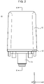
- FIG. 2 is an external view of the imaging device 10 according to the present embodiment.
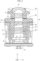
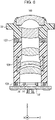
- FIG. 3 is a sectional view illustrating the main elements of the imaging device 10 according to the present embodiment.
- FIG. 3 is a sectional view illustrating the main elements contained in, for example, a housing of the imaging device 10 taken along line A-A in FIG. 2 .
- an orthogonal coordinate system is defined to correspond to the orientation of the imaging device 10.
- a z-axis direction is a direction parallel to an optical axis of the imaging device 10.
- the imaging device 10 captures an image of a subject.
- the subject is an object located in a positive z-axis direction from the imaging device 10.
- the positive z-axis direction may be referred to as a direction toward an object side or front.
- a negative z-axis direction may be referred to as a direction toward an image side or rear.
- a y-axis direction corresponds to a width direction of the imaging device 10.
- An x-axis direction corresponds to a height direction of the imaging device 10.
- the imaging device 10 includes a second lens barrel 22, an imaging optical system 20, a first lens barrel 21, an imaging element cover 33, a frame 30, a spacer 40, an imaging element 31, and a substrate 32.
- the imaging device 10 also includes a front housing 12, a rear housing 13, and a wiring unit 11.
- the imaging device 10 also includes a joining member 23.
- the imaging device 10 includes a structure in which the front housing 12 and the rear housing 13 illustrated in FIG. 2 cover the elements illustrated in FIGs. 1 and 3 . Components of the imaging device 10 are described in detail below. Note that FIGs. 1 to 3 are illustrative.
- the imaging device 10 does not necessarily include all of the components illustrated in FIGs. 1 to 3 .
- the imaging device 10 may include one or more components other than the components illustrated in FIGs. 1 to 3 .
- the front housing 12 is positioned at the front of the imaging device 10 and protects components contained in the front housing 12 from, for example, an impact.
- the front housing 12 includes an opening that does not block light that travels toward the imaging optical system 20.
- the opening in the front housing 12 exposes portions of the imaging optical system 20 and the second lens barrel 22.
- the front housing 12 may be connected to the second lens barrel 22 through, for example, the fit between a projection 22A of the second lens barrel 22 and the opening in the front housing 12.
- the front housing 12 and the second lens barrel 22 may be connected to each other by another method, for example, by an adhesive or welding.
- the front housing 12 also has a function of pressing the imaging optical system 20 rearward so that the imaging optical system 20 does not fall through the opening.
- the material of the front housing 12 may be, but is not limited to, a resin.
- the resin usable as the material of the front housing 12 include polyphenylene sulfide (PPS), polyetherimide (PEI), polyether ether ketone (PEEK), polycarbonate (PC), cycloolefin polymer (COP), ABS resin, polyethylene terephthalate (PET), and polystyrene (PS).
- PPS polyphenylene sulfide
- PEI polyetherimide
- PEEK polyether ether ketone
- PC polycarbonate
- COP cycloolefin polymer
- ABS resin polyethylene terephthalate
- PS polystyrene
- PS polystyrene
- the rear housing 13 is positioned at the rear of the imaging device 10 and protects components contained in the rear housing 13 from, for example, an impact.
- the position of the rear housing 13 may be fixed with respect to the front housing 12 while the elements illustrated in FIGs. 1 and 3 are disposed between the rear housing 13 and the front housing 12.
- the rear housing 13 and the front housing 12 may be connected to each other by, for example, an adhesive or by another method, such as welding, fitting, or screwing.
- the material of the rear housing 13 may be, but is not limited to, a resin. Examples of the resin usable as the material of the rear housing 13 include, but are not limited to, the resins mentioned in the description of the front housing 12.
- the wiring unit 11 includes wires including a line for supplying electric power to the imaging device 10 and a signal line for outputting an image signal from the imaging element 31.
- the wires of the wiring unit 11 may extend to the outside of the imaging device 10 through an opening in the rear housing 13 and be connected to an electronic device disposed outside the imaging device 10.
- the imaging optical system 20 includes at least one optical member and is designed to have desired optical characteristics, such as a focal length and a focal depth.
- the imaging optical system 20 includes a first lens 201, a lens 202, a lens 203, a second lens 204, and a lens 205 as optical members.
- the imaging optical system 20 may also include a diaphragm and an optical filter.
- the first lens 201, the lens 202, the lens 203, the second lens 204, and the lens 205 may be, for example, plastic lenses, but one or more thereof may be a glass lens or lenses.
- the number of lenses included in the imaging optical system 20 may be one or more and not more than four, or six or more.
- the first lens barrel 21 holds one or more of the lenses included in the imaging optical system 20.
- the first lens barrel 21 is disposed on the image side of the second lens barrel 22, that is, behind the second lens barrel 22.
- the first lens barrel 21 holds the first lens 201.
- the first lens barrel 21 also holds the lens 202 and the lens 203.
- the first lens 201 is positioned closest to the object side, that is, closest to the front end.
- the first lens 201, the lens 202, and the lens 203 may converge light that passes through the first lens 201, the lens 202, and the lens 203.
- a lens group held by the first lens barrel 21 is to be attached with a higher positional accuracy than a lens group held by the second lens barrel 22 described below.
- the imaging position changes by a greater amount than when the lens group held by the second lens barrel 22 moves in the optical axis direction.
- the first lens barrel 21 includes a tubular portion and a flange portion 21A.
- the tubular portion surrounds an optical axis of the imaging optical system 20.
- the flange portion 21A projects in directions crossing the optical axis of the imaging optical system 20.
- the flange portion 21A may project in directions along a plane (xy plane) orthogonal to the optical axis of the imaging optical system 20, or in directions along a plane inclined with respect to the xy plane toward the z axis.
- the flange portion 21A is positioned at an end portion of the first lens barrel 21 at the object side.
- the frame 30 is attached to the flange portion 21A.
- the flange portion 21A may include screw holes through which the flange portion 21A can be screwed to the frame 30.
- the first lens barrel 21 and the frame 30 may be connected to each other by another method, such as welding or fitting, instead of screwing.
- the material of the first lens barrel 21 may be, but is not limited to, a resin.
- the resin usable as the material of the first lens barrel 21 include, but are not limited to, the resins mentioned in the description of the front housing 12.
- the resin used as the material of the first lens barrel 21 preferably has a low hygroscopicity.
- the material of the first lens barrel 21 may be a metal, such as an aluminum alloy, a magnesium alloy, or a zinc alloy.
- the second lens barrel 22 holds one or more of the lenses included in the imaging optical system 20.
- the second lens barrel 22 is disposed on the object side of the first lens barrel 21, that is, in front of the first lens barrel 21.
- the second lens barrel 22 holds the second lens 204.
- the second lens barrel 22 also holds the lens 205.
- the second lens 204 is positioned closest to the object side, that is, closest to the front end.
- the second lens barrel 22 has a tubular shape that surrounds the optical axis of the imaging optical system 20.
- An end portion of the second lens barrel 22 at the object side is a projection 22A projecting in the positive z-axis direction, and is connectable to the front housing 12 as described above.
- the second lens 204 and the lens 205 may diffuse light that passes through the second lens 204 and the lens 205.
- the material of the second lens barrel 22 may be, but is not limited to, a resin.
- the resin usable as the material of the second lens barrel 22 include, but are not limited to, the resins mentioned in the description of the front housing 12.
- the resin used as the material of the second lens barrel 22 preferably has a low hygroscopicity.
- the material of the second lens barrel 22 may be a metal, such as an aluminum alloy, a magnesium alloy, or a zinc alloy.
- the joining member 23 joins the first lens barrel 21 and the second lens barrel 22 together.
- the joining member 23 adjusts the position of the second lens barrel 22 with respect to the first lens barrel 21 in six-axis directions so that the imaging element 31 can receive an image focused by the imaging optical system 20.
- the adjustment in the six-axis directions means an adjustment in the x-axis direction, the y-axis direction, and the z-axis direction illustrated in FIGs. 1 to 3 and rotation directions around these axes (pan, tilt, and roll).
- the joining member 23 joins an object-side end portion of the first lens barrel 21 to an image-side end portion of the second lens barrel 22.
- the joining member 23 may be an adhesive capable of providing a predetermined interval between the first lens barrel 21 and the second lens barrel 22.
- the second lens barrel 22 may be attached to the first lens barrel 21 with the adhesive.
- the predetermined interval is a small value less than a thickness adjustable by the spacer 40.
- the adhesive is preferably cured with ultraviolet light so that no optical displacement occurs due to contraction when the adhesive is cured.
- the adhesive is not limited to this, and may be a thermosetting adhesive.
- the joining member 23 may be a solder.
- the first lens barrel 21 and the second lens barrel 22 may be screwed to each other, and the joining member 23 may be a screw or a screw with a spring.
- the frame 30 is attached to the first lens barrel 21 and the substrate 32 on which the imaging element 31 is mounted.
- the frame 30 includes an interior space that contains at least a portion of the first lens barrel 21.
- an object-side end portion of the frame 30 is screwed to the flange portion 21A of the first lens barrel 21.
- the first lens 201 may have various shapes depending on the design of the imaging optical system 20. Therefore, in the following description, positional relationships are described with reference to a center of gravity G of the first lens 201.
- an attachment position C at which the frame 30 and the flange portion 21A are joined together is on the object side of the center of gravity G of the first lens 201.
- the frame 30 is attached to the first lens barrel 21 at a position on the object side of the first lens 201.
- Such a structure facilitates calculation of influence of an environmental change on the imaging device 10 and allows for easier optical design. That is, a change in the shape of the first lens barrel 21, a resulting change in performances of the lenses held by the first lens barrel 21, and a change in the shape of the frame 30 can be calculated using the attachment position C as a common reference position.
- an environmental change such as changes in temperature and humidity
- the first lens barrel 21 and the frame 30 each expand or contract with reference to the attachment position C, and therefore the lenses held by the first lens barrel 21 may be easily maintained focused on the imaging element 31.
- a predetermined interval that is, a gap
- the optical performance is maintained as long as the change in shape occurs within the gap.
- a portion of the first lens barrel 21 other than the flange portion 21A comes into contact with the frame 30, and the optical performance may be degraded.
- the frame 30 is attached to the substrate 32 with the spacer 40 disposed between the frame 30 and the substrate 32. As illustrated in FIG. 1 , the frame 30 may be screwed to the substrate 32 with the imaging element cover 33 and the spacer 40 disposed between the frame 30 and the substrate 32.
- the material of the frame 30 may be, but is not limited to, a metal.
- the metal used as the material of the frame 30 include an aluminum alloy, such as ADC12, a magnesium alloy, and a zinc alloy.
- the frame 30 may be a die casting to ensure high dimensional accuracy.
- the imaging element cover 33 includes an opening that does not block a subject image that travels from the imaging optical system 20 to a light-receiving surface of the imaging element 31. Due to the imaging element cover 33, ambient light other than the subject image is not incident on the light-receiving surface of the imaging element 31.
- the material of the imaging element cover 33 may be, but is not limited to, a resin.
- the spacer 40 is positioned between the frame 30 and the substrate 32, and serves to adjust the interval between the frame 30 and the substrate 32 in one-axis direction (z-axis direction).
- One or more spacers 40 are inserted between the frame 30 and the substrate 32.
- the interval between the frame 30 and the substrate 32 in the z-axis direction is adjusted by the thickness or number of the one or more spacers 40.
- the one or more spacers 40 may serve to adjust the interval between the frame 30 and the substrate 32 in the z-axis direction to position the imaging element 31 so that the imaging element 31 can receive the image focused by the imaging optical system 20.
- the interval in the z-axis direction may be adjusted by the change in the number of the one or more spacers 40 that are inserted.
- the thickness of each spacer 40 in the z direction may be 50 ⁇ m. In this case, the interval in the z-axis direction may be adjusted in steps of 50 ⁇ m.
- the thickness of each spacer 40 in the z direction is preferably as small as possible, and is preferably not more than 100 ⁇ m, for example. More preferably, the thickness of each spacer 40 in the z direction is not more than 50 ⁇ m. Still more preferably, the thickness of each spacer 40 in the z direction is not more than 20 ⁇ m. Two or more spacers 40 with different thicknesses in the z direction may be used.
- the thickness of each spacer 40 may be set by various processes, such as polishing or etching.
- the material of the one or more spacers 40 may be, but is not limited to, a metal.
- the material of the one or more spacers 40 preferably has a low coefficient of linear expansion.
- the metal used as the material of the one or more spacers 40 may be, for example, a stainless steel having a coefficient of linear expansion of not more than 16.
- the material of the one or more spacers 40 may be a ceramic.
- the one or more spacers 40 may be made of a resin as long as the resin has a low coefficient of linear expansion.
- the imaging element 31 is disposed on the image side of the imaging optical system 20.
- the imaging element 31 is capable of receiving the subject image focused by the imaging optical system 20.
- the imaging element 31 captures the subject image focused on the light-receiving surface, converts the subject image into an image signal, and outputs the image signal.
- the imaging element 31 may be, for example, a charge coupled device (CCD) or a complementary metal oxide semiconductor (CMOS) image sensor.
- CCD charge coupled device
- CMOS complementary metal oxide semiconductor
- the substrate 32 is a circuit board. Electronic components including at least the imaging element 31 are mounted on the substrate 32.
- the imaging element 31 is mounted on a front surface of the substrate 32. In other words, the imaging element 31 is mounted on the substrate 32 so that the light-receiving surface of the imaging element 31 is capable of receiving the subject image focused by the imaging optical system 20.
- the position of the substrate 32 is fixed with respect to the frame 30 while the imaging element cover 33 and the one or more spacers 40 are disposed between the substrate 32 and the frame 30.
- the substrate 32 may include screw holes having a diameter greater than the diameter of screws with which the substrate 32 can be screwed to the frame 30.
- the position of the substrate 32 is adjusted in two-axis directions, which are the x-axis direction and the y-axis direction, and the subject image is focused on the light-receiving surface of the imaging element 31.
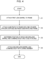
- FIG. 4 illustrates an example of a method for manufacturing the imaging device 10 according to the embodiment of the present disclosure.
- the imaging device 10 including the above-described configuration may be manufactured in accordance with the flowchart of FIG. 4 .
- the first lens barrel 21 is attached to the frame 30 (step S1). More specifically, the flange portion 21A of the first lens barrel 21 is screwed to the front of the frame 30.
- the substrate 32 is attached to the frame 30 with the one or more spacers 40 disposed between the substrate 32 and the frame 30 (step S2, substrate attaching step). More specifically, the substrate 32 on which the imaging element 31 is mounted is screwed to the rear of the frame 30 with the one or more spacers 40 disposed between the substrate 32 and the frame 30. In step S2, the position of the imaging element 31 on the substrate 32 with respect to the frame 30 in the z-axis direction may be adjusted by the thickness or number of the one or more spacers 40 that are inserted.
- the position of the imaging element 31 with respect to the frame 30 in the x-axis and y-axis directions may be adjusted by the position at which the substrate 32 is screwed to the frame 30.
- the thickness in the z-axis direction or number of the one or more spacers 40 to be inserted may be determined in advance through measurement using a measurement device.
- the focal position of the lenses on the first lens barrel 21 attached to the frame 30 may be measured with the measurement device to determine a target thickness of the one or more spacers 40 in the z-axis direction.
- the imaging optical system 20 may be measured while the second lens barrel 22 is temporarily placed on the frame 30 to which the first lens barrel is attached.
- the target thickness of the one or more spacers 40 in the z-axis direction is a thickness that enables the imaging optical system 20 to focus the subject image on the light-receiving surface of the imaging element 31 when the second lens barrel 22 is attached to the frame 30.
- the second lens barrel 22 is attached to the frame 30 with the joining member 23 having a predetermined thickness after the first lens barrel 21 and the substrate 32 are attached to the frame 30.
- an attachment position at which the second lens barrel 22 is to be attached to a combined body is determined (step S3).
- the combined body is composed of the frame 30 to which the first lens barrel is attached. More specifically, the combined body includes the frame 30 to which the first lens barrel 21 and the substrate 32 are attached.
- the attachment position is determined so that the light-receiving surface of the imaging element 31 can receive the subject image focused by the imaging optical system 20.
- the attachment position may be determined so that an optical axis of the second lens 204 and the lens 205 held by the second lens barrel 22 coincides with an optical axis of the first lens 201, the lens 202, and the lens 203 held by the first lens barrel 21.
- the second lens barrel 22 and the combined body are attached to each other with the joining member 23 (step S4).
- the joining member 23 attaches the second lens barrel 22 and the frame 30 to each other after an adjustment in the six-axis directions.
- the joining member 23 provides a predetermined interval between the second lens barrel 22 and the first lens barrel 21 to adjust an interval that cannot be adjusted by the one or more spacers 40.
- each spacer 40 preferably has a thickness of not more than 100 ⁇ m.
- the joining member 23 may have a thickness of less than 100 ⁇ m that is not adjustable by the one or more spacers 40.
- the joining member 23 may be a small amount of adhesive with a thickness of less than 100 ⁇ m.
- the volume of an adhesive changes due to temperature increase and moisture absorption.
- the joining member 23 is composed of a small amount of adhesive, the volume changes only by a small amount in response to temperature increase and moisture absorption.
- the second lens barrel 22 and the combined body are attached to each other with the joining member 23 after the frame 30 and the substrate 32 are attached to each other with the one or more spacers 40 whose thickness or number is set.
- the positional relationship between the first lens barrel 21 and the imaging element 31 is determined based on the thickness or number of the one or more spacers 40. Therefore, the distance between the second lens barrel 22 and the position at which the frame 30 is attached is roughly determined.
- the joining member 23 may be composed of a predetermined small amount of adhesive. In this case, an assembly clearance is substantially constant.
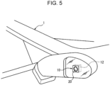
- the imaging device 10 including the above-described configuration may be installed in a vehicle 1 as, for example, an onboard camera.
- the imaging device 10 may be fixed externally to the front of the vehicle 1 to record the behavior of a vehicle in front of the vehicle 1.
- the imaging device 10 may be fixed externally to the rear of the vehicle 1 to record the behavior of a vehicle behind the vehicle 1.
- the imaging device 10 may be disposed in a side mirror and constitute an electronic mirror. In such a case, the imaging device 10 may capture an image of an area behind the vehicle 1 and provide a driver with the image as driving assistance information.
- the image captured by the imaging device 10 may be displayed on a display device disposed in a cabin of the vehicle 1.
- the display device may be disposed on, for example, a rear-view mirror or an instrument panel so that the driver can see the display device while driving the vehicle 1.
- the imaging device 10 installed in the vehicle 1 as an onboard camera is used in an environment with larger temperature and humidity variations compared to an indoor environment. Large changes in temperature and humidity may cause the components of the imaging device 10 to expand or contract. As described below, in the present embodiment, the imaging device 10 has an optical performance with less degradation due to a change in the operating environment. Therefore, the imaging device 10 is suitable for use as an onboard camera.
- the imaging device 10 includes a nesting structure in which the first lens barrel 21 is disposed in the interior space of the frame 30 with a gap provided between the first lens barrel 21 and the frame 30 (see FIG. 3 ).
- the optical performance is maintained as long as the change in shape occurs within the gap. Therefore, even when the shape of the first lens barrel 21 changes due to an environmental change, such as changes in temperature and humidity, the optical performance can be maintained unless the shape of the first lens barrel 21 changes beyond the gap.
- the shapes of the first lens barrel 21 and the frame 30 change in the same direction in response to an environmental change.
- the frame 30 also expands in the z-axis direction (see FIG. 3 ).
- the position of the imaging element 31 mounted on the substrate 32 attached to the frame 30 moves in the negative z-axis direction. Therefore, the image focused on the light-receiving surface of the imaging element 31 is not easily displaced.
- the shapes of the first lens barrel 21 and the frame 30 change due to a temperature increase, the shapes change in the same direction. Therefore, the light-receiving surface of the imaging element 31 can receive the subject image focused by the imaging optical system 20.
- the attachment position C at which the frame 30 and the flange portion 21A are joined together is on the object side of the center of gravity G of the first lens 201.
- the first lens 201 is positioned closest to the object side. More specifically, the attachment position C may be at end portions of the first lens barrel 21 and the frame 30 at the object side. Therefore, when the first lens barrel 21 and the frame 30 expand or contract in the z-axis direction due to a temperature change, the first lens barrel 21 and the frame 30 individually expand or contract in the same direction from the same reference point (attachment position C). Accordingly, the lenses of the imaging optical system 20 are maintained focused on the imaging element 31 despite the expansion or contraction of the first lens barrel 21. Thus, degradation in the optical performance due to an environmental change can be reduced.
- the frame 30 may have a coefficient of linear expansion less than that of the first lens barrel 21.
- the frame 30 is attached to the first lens barrel 21 and the substrate 32 on which the imaging element 31 is mounted. Accordingly, a change in shape of the frame 30 affects the positions of the first lens barrel 21 and the imaging element 31, and is therefore preferably small.
- a change in shape (expansion) of the first lens barrel 21 is relatively greater than that of the frame 30.
- the first lens barrel 21 and the frame 30 are spaced from each other by a gap and do not come into contact with each other in an environment in which the imaging device 10 is normally used.
- the frame 30 is attached to the substrate 32 with the one or more spacers 40 disposed between the frame 30 and the substrate 32. Therefore, the position of the imaging element 31 is adjusted by the thickness or number of the one or more spacers 40 so that the imaging element 31 can receive the image focused by the imaging optical system 20.
- Each spacer 40 is a member made of, for example, a metal or a ceramic having a thickness of, for example, not more than 100 ⁇ m.
- the position of the imaging element 31 can be finely adjusted by the one or more spacers 40.
- the coefficient of linear expansion of the material is less than that of a resin, and a change in volume caused by an environmental change, such as changes in temperature and humidity, can be reduced.
- the second lens barrel 22 and the frame 30 are joined together with the joining member 23.
- the joining member 23 has a small thickness that is less than the thickness of each spacer 40 and is composed of, for example, a small amount of adhesive. Therefore, the volume of the joining member 23 changes only by a small amount in response to temperature increase and moisture absorption.
- FIG. 6 is a sectional view of an imaging device 110 according to a comparative example including no frame 30.
- the imaging device 110 includes a second lens barrel 22 and a substrate 32 on which an imaging element 31 is mounted.
- the second lens barrel 22, the substrate 32, and the imaging element 31 are the same as those included in the imaging device 10 according to the present embodiment.
- the second lens barrel 22 and the substrate 32 are connected to a first lens barrel 121 including no flange with an adhesive portion 123 and an adhesive portion 124, respectively.
- the adhesive portion 123 and the adhesive portion 124 are adhesives.
- the imaging device 110 when the shape of the first lens barrel 121 changes due to an environmental change, such as changes in temperature and humidity, the change in shape of the first lens barrel 121 affects the positional relationship between the lens group on the first lens barrel 121, the second lens barrel 22, and the imaging element 31 along the optical axis. As illustrated in FIG. 6 , when the first lens barrel 121 expands in the z-axis direction, the imaging optical system 20 is deformed, and the imaging element 31 moves away from an incident portion. In the imaging device 110 according to the comparative example, the position of the substrate 32 is adjusted not by the one or more spacers 40 but by the adhesive portion 124, which is an adhesive.
- the adhesive portion 124 is deformed due to temperature increase and moisture absorption, and the deformation affects the reception of the image by the imaging element 31.
- the imaging device 110 includes the adhesive portion 123, which is an adhesive, but includes no spacers 40. Therefore, the amount of adhesive cannot be reduced. Accordingly, the adhesive portion 123 is deformed due to the influence of temperature increase and moisture absorption, and the deformation affects an optical path of the imaging optical system 20. Thus, in the imaging device 110 according to the comparative example, the optical performance is inevitably degraded due to an environmental change, such as changes in temperature and humidity.
- the imaging device 10 includes the above-described configuration and therefore has an optical performance with less degradation due to an environmental change, such as changes in temperature and humidity.
- the above-described manufacturing method enables manufacture of the imaging device 10 having an optical performance with less degradation.
- the imaging device 10 may include a processor that executes a process based on the image signal from the imaging element 31.
- the processor may output the processed image signal to the outside of the imaging device 10 through the wiring unit 11.
- the process performed by the processor based on the image signal may be, for example, an image process for adjusting brightness in accordance with external light, or an image process for displaying an image emphasizing a specified object included in the captured image. Examples of the specified object include a traffic sign and a white line on the road.
- the imaging device 10 may include a heat transfer member for dissipating heat generated by the imaging element 31.
- the heat transfer member may be disposed between the front housing 12 and the imaging element 31 or between the rear housing 13 and the imaging element 31.
- the heat transfer member is, for example, a flexible heat transfer sheet.
- the material of the heat transfer member may be, for example, silicone. However, the material is not limited to this, and may be another material that transfers heat.
Landscapes
- Physics & Mathematics (AREA)
- General Physics & Mathematics (AREA)
- Optics & Photonics (AREA)
- Lens Barrels (AREA)
- Studio Devices (AREA)
Applications Claiming Priority (2)
| Application Number | Priority Date | Filing Date | Title |
|---|---|---|---|
| JP2020071278A JP7382271B2 (ja) | 2020-04-10 | 2020-04-10 | 撮像装置 |
| PCT/JP2021/014390 WO2021206027A1 (fr) | 2020-04-10 | 2021-04-02 | Dispositif d'imagerie |
Publications (2)
| Publication Number | Publication Date |
|---|---|
| EP4134721A1 true EP4134721A1 (fr) | 2023-02-15 |
| EP4134721A4 EP4134721A4 (fr) | 2024-05-22 |
Family
ID=78023139
Family Applications (1)
| Application Number | Title | Priority Date | Filing Date |
|---|---|---|---|
| EP21785002.3A Withdrawn EP4134721A4 (fr) | 2020-04-10 | 2021-04-02 | Dispositif d'imagerie |
Country Status (5)
| Country | Link |
|---|---|
| US (1) | US20230152552A1 (fr) |
| EP (1) | EP4134721A4 (fr) |
| JP (1) | JP7382271B2 (fr) |
| CN (1) | CN115380233A (fr) |
| WO (1) | WO2021206027A1 (fr) |
Family Cites Families (14)
| Publication number | Priority date | Publication date | Assignee | Title |
|---|---|---|---|---|
| JP2002014269A (ja) | 2000-06-29 | 2002-01-18 | Sony Corp | 光学装置 |
| JP4674130B2 (ja) * | 2005-07-21 | 2011-04-20 | 日東光学株式会社 | レンズ保持ユニット |
| JP2008304641A (ja) | 2007-06-06 | 2008-12-18 | Sumitomo Electric Ind Ltd | レンズユニット、撮像装置及び画像処理システム |
| ES2693455T3 (es) * | 2009-03-25 | 2018-12-11 | Magna Electronics Inc. | Montaje de cámara y lente vehicular |
| JP5482231B2 (ja) | 2010-01-26 | 2014-05-07 | 株式会社リコー | 撮像装置 |
| CN105103026B (zh) * | 2013-04-09 | 2017-05-31 | 富士胶片株式会社 | 摄像装置 |
| WO2015064614A1 (fr) | 2013-10-30 | 2015-05-07 | オリンパスメディカルシステムズ株式会社 | Dispositif de capture d'image |
| JP6578279B2 (ja) * | 2014-08-01 | 2019-09-18 | 日本電産コパル株式会社 | 撮像装置、光学機器、電子機器、車両および撮像装置の製造方法 |
| JP2016177195A (ja) * | 2015-03-20 | 2016-10-06 | 株式会社リコー | マイクロレンズ基板及び撮像装置 |
| JP6912530B2 (ja) * | 2015-05-15 | 2021-08-04 | マクセル株式会社 | カメラ |
| JP2018120019A (ja) * | 2017-01-23 | 2018-08-02 | 日本電産コパル株式会社 | 撮像装置 |
| EP3605177B1 (fr) | 2017-03-24 | 2026-05-06 | Ningbo Sunny Opotech Co., Ltd. | Objectif divisé, module de caméra et appareil électronique |
| JP2019028140A (ja) * | 2017-07-26 | 2019-02-21 | 日本電産コパル株式会社 | 撮像装置 |
| US12510721B2 (en) * | 2018-03-16 | 2025-12-30 | Ningbo Sunny Opotech Co., Ltd | Imaging optical device and manufacturing method therefor |
-
2020
- 2020-04-10 JP JP2020071278A patent/JP7382271B2/ja active Active
-
2021
- 2021-04-02 WO PCT/JP2021/014390 patent/WO2021206027A1/fr not_active Ceased
- 2021-04-02 US US17/995,833 patent/US20230152552A1/en not_active Abandoned
- 2021-04-02 CN CN202180027243.2A patent/CN115380233A/zh active Pending
- 2021-04-02 EP EP21785002.3A patent/EP4134721A4/fr not_active Withdrawn
Also Published As
| Publication number | Publication date |
|---|---|
| JP7382271B2 (ja) | 2023-11-16 |
| WO2021206027A1 (fr) | 2021-10-14 |
| EP4134721A4 (fr) | 2024-05-22 |
| CN115380233A (zh) | 2022-11-22 |
| US20230152552A1 (en) | 2023-05-18 |
| JP2021167903A (ja) | 2021-10-21 |
Similar Documents
| Publication | Publication Date | Title |
|---|---|---|
| CN115933127A (zh) | 成像镜头模块、相机模块及电子装置 | |
| US12007619B2 (en) | Imaging lens system, image capturing unit and electronic device | |
| CN113777738A (zh) | 变焦镜组、镜头组件、摄像装置、电子设备及变焦方法 | |
| US20240353649A1 (en) | Imaging lens system having retaining element and electronic device | |
| US20230296863A1 (en) | Lens element, imaging lens assembly, camera module and electronic device | |
| US7570439B2 (en) | Optical module and optical system | |
| JP7382272B2 (ja) | 撮像装置の製造方法および撮像装置 | |
| EP4134721A1 (fr) | Dispositif d'imagerie | |
| US20190253590A1 (en) | Camera Module | |
| JP2002182270A (ja) | カメラモジュール及びその製造方法 | |
| EP4492804B1 (fr) | Module de caméra et dispositif électronique | |
| JP7203602B2 (ja) | レンズユニットおよびカメラモジュール | |
| JP2020134761A (ja) | レンズユニットおよびカメラモジュール | |
| US20260118625A1 (en) | Imaging lens, camera module and electronic device | |
| CN223551938U (zh) | 成像镜头、相机模块、电子装置及移动运输工具 | |
| EP4455780B1 (fr) | Module d'objectif, module de caméra et dispositif électronique | |
| TW202611585A (zh) | 成像鏡頭、相機模組、電子裝置及移動運輸工具 | |
| US20250294254A1 (en) | Sensor having ois with af functionality driving module and photographing device | |
| CN222379935U (zh) | 成像镜头模块、相机模块及电子装置 | |
| TWI905672B (zh) | 成像鏡頭模組、相機模組與電子裝置 | |
| US20250116916A1 (en) | Camera module and electronic device | |
| JP2025039525A (ja) | 光学機器、車載カメラ、及び、輸送機器 | |
| JP7827414B2 (ja) | レンズユニット、カメラモジュール、車載システムおよび車両 | |
| US20250264785A1 (en) | Light-folded camera module and electronic device | |
| JP2022113407A (ja) | 撮像モジュール |
Legal Events
| Date | Code | Title | Description |
|---|---|---|---|
| STAA | Information on the status of an ep patent application or granted ep patent |
Free format text: STATUS: THE INTERNATIONAL PUBLICATION HAS BEEN MADE |
|
| PUAI | Public reference made under article 153(3) epc to a published international application that has entered the european phase |
Free format text: ORIGINAL CODE: 0009012 |
|
| STAA | Information on the status of an ep patent application or granted ep patent |
Free format text: STATUS: REQUEST FOR EXAMINATION WAS MADE |
|
| 17P | Request for examination filed |
Effective date: 20221005 |
|
| AK | Designated contracting states |
Kind code of ref document: A1 Designated state(s): AL AT BE BG CH CY CZ DE DK EE ES FI FR GB GR HR HU IE IS IT LI LT LU LV MC MK MT NL NO PL PT RO RS SE SI SK SM TR |
|
| P01 | Opt-out of the competence of the unified patent court (upc) registered |
Effective date: 20230508 |
|
| DAV | Request for validation of the european patent (deleted) | ||
| DAX | Request for extension of the european patent (deleted) | ||
| A4 | Supplementary search report drawn up and despatched |
Effective date: 20240422 |
|
| RIC1 | Information provided on ipc code assigned before grant |
Ipc: B60R 1/22 20220101ALN20240416BHEP Ipc: G03B 30/00 20210101ALI20240416BHEP Ipc: G02B 7/02 20210101AFI20240416BHEP |
|
| STAA | Information on the status of an ep patent application or granted ep patent |
Free format text: STATUS: THE APPLICATION IS DEEMED TO BE WITHDRAWN |
|
| 18D | Application deemed to be withdrawn |
Effective date: 20241112 |