EP4134750A1 - Intelligentes korrekturvorrichtungssteuerungssystem für hochauflösende photolithographische präzisionsmaske - Google Patents
Intelligentes korrekturvorrichtungssteuerungssystem für hochauflösende photolithographische präzisionsmaske Download PDFInfo
- Publication number
- EP4134750A1 EP4134750A1 EP21796326.3A EP21796326A EP4134750A1 EP 4134750 A1 EP4134750 A1 EP 4134750A1 EP 21796326 A EP21796326 A EP 21796326A EP 4134750 A1 EP4134750 A1 EP 4134750A1
- Authority
- EP
- European Patent Office
- Prior art keywords
- subsystem
- mask
- control
- way
- sixteen
- Prior art date
- Legal status (The legal status is an assumption and is not a legal conclusion. Google has not performed a legal analysis and makes no representation as to the accuracy of the status listed.)
- Granted
Links
Images


Classifications
-
- G—PHYSICS
- G03—PHOTOGRAPHY; CINEMATOGRAPHY; ANALOGOUS TECHNIQUES USING WAVES OTHER THAN OPTICAL WAVES; ELECTROGRAPHY; HOLOGRAPHY
- G03F—PHOTOMECHANICAL PRODUCTION OF TEXTURED OR PATTERNED SURFACES, e.g. FOR PRINTING, FOR PROCESSING OF SEMICONDUCTOR DEVICES; MATERIALS THEREFOR; ORIGINALS THEREFOR; APPARATUS SPECIALLY ADAPTED THEREFOR
- G03F7/00—Photomechanical, e.g. photolithographic, production of textured or patterned surfaces, e.g. printing surfaces; Materials therefor, e.g. comprising photoresists; Apparatus specially adapted therefor
- G03F7/70—Microphotolithographic exposure; Apparatus therefor
- G03F7/70691—Handling of masks or workpieces
- G03F7/70783—Handling stress or warp of chucks, masks or workpieces, e.g. to compensate for imaging errors or considerations related to warpage of masks or workpieces due to their own weight
-
- G—PHYSICS
- G03—PHOTOGRAPHY; CINEMATOGRAPHY; ANALOGOUS TECHNIQUES USING WAVES OTHER THAN OPTICAL WAVES; ELECTROGRAPHY; HOLOGRAPHY
- G03F—PHOTOMECHANICAL PRODUCTION OF TEXTURED OR PATTERNED SURFACES, e.g. FOR PRINTING, FOR PROCESSING OF SEMICONDUCTOR DEVICES; MATERIALS THEREFOR; ORIGINALS THEREFOR; APPARATUS SPECIALLY ADAPTED THEREFOR
- G03F9/00—Registration or positioning of originals, masks, frames, photographic sheets or textured or patterned surfaces, e.g. automatically
- G03F9/70—Registration or positioning of originals, masks, frames, photographic sheets or textured or patterned surfaces, e.g. automatically for microlithography
- G03F9/7003—Alignment type or strategy, e.g. leveling, global alignment
- G03F9/7023—Aligning or positioning in direction perpendicular to substrate surface
- G03F9/7026—Focusing
-
- G—PHYSICS
- G03—PHOTOGRAPHY; CINEMATOGRAPHY; ANALOGOUS TECHNIQUES USING WAVES OTHER THAN OPTICAL WAVES; ELECTROGRAPHY; HOLOGRAPHY
- G03F—PHOTOMECHANICAL PRODUCTION OF TEXTURED OR PATTERNED SURFACES, e.g. FOR PRINTING, FOR PROCESSING OF SEMICONDUCTOR DEVICES; MATERIALS THEREFOR; ORIGINALS THEREFOR; APPARATUS SPECIALLY ADAPTED THEREFOR
- G03F7/00—Photomechanical, e.g. photolithographic, production of textured or patterned surfaces, e.g. printing surfaces; Materials therefor, e.g. comprising photoresists; Apparatus specially adapted therefor
- G03F7/70—Microphotolithographic exposure; Apparatus therefor
- G03F7/70058—Mask illumination systems
- G03F7/70208—Multiple illumination paths, e.g. radiation distribution devices, microlens illumination systems, multiplexers or demultiplexers for single or multiple projection systems
-
- G—PHYSICS
- G03—PHOTOGRAPHY; CINEMATOGRAPHY; ANALOGOUS TECHNIQUES USING WAVES OTHER THAN OPTICAL WAVES; ELECTROGRAPHY; HOLOGRAPHY
- G03F—PHOTOMECHANICAL PRODUCTION OF TEXTURED OR PATTERNED SURFACES, e.g. FOR PRINTING, FOR PROCESSING OF SEMICONDUCTOR DEVICES; MATERIALS THEREFOR; ORIGINALS THEREFOR; APPARATUS SPECIALLY ADAPTED THEREFOR
- G03F9/00—Registration or positioning of originals, masks, frames, photographic sheets or textured or patterned surfaces, e.g. automatically
- G03F9/70—Registration or positioning of originals, masks, frames, photographic sheets or textured or patterned surfaces, e.g. automatically for microlithography
- G03F9/7088—Alignment mark detection, e.g. TTR, TTL, off-axis detection, array detector, video detection
-
- G—PHYSICS
- G05—CONTROLLING; REGULATING
- G05B—CONTROL OR REGULATING SYSTEMS IN GENERAL; FUNCTIONAL ELEMENTS OF SUCH SYSTEMS; MONITORING OR TESTING ARRANGEMENTS FOR SUCH SYSTEMS OR ELEMENTS
- G05B19/00—Program-control systems
- G05B19/02—Program-control systems electric
- G05B19/04—Program control other than numerical control, i.e. in sequence controllers or logic controllers
- G05B19/05—Programmable logic controllers, e.g. simulating logic interconnections of signals according to ladder diagrams or function charts
- G05B19/056—Programming the PLC
-
- G—PHYSICS
- G06—COMPUTING OR CALCULATING; COUNTING
- G06T—IMAGE DATA PROCESSING OR GENERATION, IN GENERAL
- G06T7/00—Image analysis
- G06T7/0002—Inspection of images, e.g. flaw detection
- G06T7/0004—Industrial image inspection
-
- H—ELECTRICITY
- H04—ELECTRIC COMMUNICATION TECHNIQUE
- H04N—PICTORIAL COMMUNICATION, e.g. TELEVISION
- H04N25/00—Circuitry of solid-state image sensors [SSIS]; Control thereof
- H04N25/70—SSIS architectures; Circuits associated therewith
- H04N25/71—Charge-coupled device [CCD] sensors; Charge-transfer registers specially adapted for CCD sensors
-
- G—PHYSICS
- G05—CONTROLLING; REGULATING
- G05B—CONTROL OR REGULATING SYSTEMS IN GENERAL; FUNCTIONAL ELEMENTS OF SUCH SYSTEMS; MONITORING OR TESTING ARRANGEMENTS FOR SUCH SYSTEMS OR ELEMENTS
- G05B2219/00—Program-control systems
- G05B2219/10—Plc systems
- G05B2219/13—Plc programming
- G05B2219/13004—Programming the plc
-
- H—ELECTRICITY
- H04—ELECTRIC COMMUNICATION TECHNIQUE
- H04N—PICTORIAL COMMUNICATION, e.g. TELEVISION
- H04N23/00—Cameras or camera modules comprising electronic image sensors; Control thereof
- H04N23/60—Control of cameras or camera modules
- H04N23/695—Control of camera direction for changing a field of view, e.g. pan, tilt or based on tracking of objects
Definitions
- the present disclosure relates to a field of lithography technology, and in particular, to an intelligent correction device control system for a super-resolution lithography precision mask.
- a USB serial port transmission or an Ethernet port transmission is mostly used as an image processing and acquisition manner.
- the transmission speeds of these transmission manners are relatively slow, an efficiency of a subsequent processing through a control system will be reduced, and all image processing operations are completed by a host computer control system.
- a control system having a higher control precision is also required at present, and an alignment and a mask correction may be completed accurately, quickly and stably through this system.
- the present disclosure provides an intelligent correction device control system for a super-resolution lithography precision mask, so as to solve at least portion of the above problems.
- an intelligent correction device control system for a super-resolution lithography precision mask including: a sixteen-way pneumatic fine-tuning mask deformation control subsystem configured to deform a mask, detect a force value of a mask deformation, compare the force value of the mask deformation with an output force set value, and generate a first control feedback quantity to adjust a force deforming the mask, so as to control a deformation quantity of the mask; and an alignment subsystem configured to acquire images of the mask and a substrate, and adjust a position between the mask and the substrate according to the images, so as to align the mask with the substrate.
- the sixteen-way pneumatic fine-tuning mask deformation control subsystem includes a PLC controller subsystem, the PLC controller subsystem including: a PID controller, an analog input extension module, an analog output extension module, a digital input extension module and a digital output extension module; wherein, the analog input extension module is configured to perform an A/D conversion to an acquired analog electrical signal of the force value; the digital input extension module is configured to input a digital signal obtained by the A/D conversion to the PID controller; the PID controller is configured to compare the digital signal obtained by the A/D conversion with the output force set value, and generate the first control feedback quantity; the digital output extension module is configured to output a digital signal of the first control feedback quantity to the analog output extension module; and the analog output extension module is configured to perform a D/A conversion to the digital signal of the first control feedback quantity, and output an analog electrical signal of the first control feedback quantity obtained by the conversion, so as to form a closed-loop feedback to the mask deformation.
- the analog input extension module is configured to perform an A/
- the sixteen-way pneumatic fine-tuning mask deformation control subsystem further includes an air pressure output control subsystem, the air pressure output control subsystem including: a sixteen-way cylinder and a sixteen-way electro-pneumatic proportional valve; the sixteen-way cylinder is configured to output the force deforming the mask, and the sixteen-way electro-pneumatic proportional valve is configured to control an intensity of an output force of the sixteen-way cylinder according to the first control feedback quantity.
- the sixteen-way pneumatic fine-tuning mask deformation control subsystem further includes a mask force detection feedback subsystem, the mask force detection feedback subsystem including: a sixteen-way force sensor configured to acquire the force value of the mask deformation; and a pressure sensor configured to acquire an air pressure in a connection air pipe of the sixteen-way air cylinder.
- the PLC controller subsystem is further configured to compare the air pressure with a preset air pressure value, and generate a second control feedback quantity;
- the sixteen-way pneumatic fine-tuning mask deformation control subsystem further includes a commutating solenoid valve configured to control a direction of the output force of the sixteen-way cylinder according to the second control feedback quantity; and the PLC controller subsystem is connected with the solenoid valve through an intermediate relay.
- the alignment subsystem includes: an eight-way image acquisition CCD camera, wherein each way of the CCD camera is provided with a telecentric lens for acquiring the images; two image acquisition cards, wherein each of the image acquisition cards is configured to receive and transmit images acquired by four-ways of the CCD camera; an image processor configured to preprocess the images, transmit the preprocessed images to a central control system, allow the central control system to judge whether the mask is aligned with the substrate according to the images, and generate a regulation instruction for aligning the mask with the substrate; an image acquisition adjustment motor control subsystem configured to adjust a position of the substrate according to the regulation instruction, so as to align the substrate with the mask; and an eight-way illuminating subsystem configured to provide an illumination for the telecentric lens connected with each way of the CCD camera.
- the system further includes: a host computer, wherein a central control system is built in the host computer; wherein the host computer is configured to issue a program instruction to the PLC controller subsystem according to an actual mask deformation control requirement, and the program instruction is configured to generate the first control feedback quantity and regulate the sixteen-way pneumatic fine-tuning mask deformation control subsystem to adjust the deformation quantity of the mask; and the host computer is further configured to judge whether the mask is aligned with the substrate according to the images, and generate a regulation instruction for aligning the mask with the substrate.
- the host computer is in connection and communication with the sixteen-way pneumatic fine-tuning mask deformation control subsystem through an industrial Ethernet bus
- the host computer is in connection and communication with the alignment subsystem through an industrial Ethernet bus, a PCIe bus or an RS232 serial port communication bus
- the image acquisition card is in connection and communication with the host computer through a PCIe X4 interface.
- the alignment subsystem further includes: a compact linear displacement stage configured to adjust a position of the CCD camera; and a multi-channel motion controller configured to move the compact linear displacement stage for a position adjustment according to the regulation instruction issued by the central control system.
- an intelligent correction device control system for a super-resolution lithography precision mask including a sixteen-way pneumatic fine-tuning mask deformation control subsystem and an alignment subsystem, wherein the sixteen-way pneumatic fine-tuning mask deformation control subsystem comprises a mask force detection feedback subsystem, an air pressure output control subsystem, and a PID controller subsystem achieved by a PLC, wherein the alignment subsystem comprises an eight-way image acquisition CCD, an image acquisition card, an image processor and an eight-way illuminating subsystem, and wherein image data acquired by the image acquisition CCD is transmitted to a high-performance host computer through the image acquisition card, the host computer preprocesses a related image through the image processor and then makes a feedback to a central control system, so as to provide an image support for an alignment program, and the eight-way illuminating subsystem is connected with a phase modulator through a signal generator to generate an excitation signal, so that a light emitted by a
- a standard control bus is used as a control bus of the system; and an industrial Ethernet bus based on a TCP/IP protocol or a customizable industrial Ethernet bus is used by the sixteen-way pneumatic fine-tuning mask deformation control subsystem.
- the sixteen-way pneumatic fine-tuning mask deformation control subsystem further comprises a PLC controller subsystem and analog input and output extension modules, a PID controller inside the PLC, a mask force detection feedback subsystem and an air pressure output control subsystem.
- an industrial Ethernet bus based on a TCP/IP protocol or a customizable industrial Ethernet bus is used by the alignment subsystem, or a PCIe bus based on a PCIe X4 or a customizable PCIe bus is used by the alignment subsystem, or an RS232 serial port communication bus based on a USRT or a customizable RS232 serial port communication bus is used by the alignment subsystem.
- the alignment subsystem includes a multi-channel image acquisition subsystem, an image transmission subsystem, and an image processing subsystem, an image acquisition adjustment motor control subsystem and an eight-way illuminating subsystem.
- the system comprises: a high-performance industrial computer for an operation of the system and a high-speed image processing calculation.
- the PLC controller subsystem includes: a PLC controller for providing a sixteen-way PID controller to complete an output force closed-loop control algorithm; an analog input extension module for a force sensor analog input conversion to complete a feedback force D/A conversion, and also for an input air pressure detection to complete a D/A conversion; an analog output extension module for an electro-pneumatic proportional valve control signal output to complete an A/D conversion; a digital output extension module for a cylinder output commutation control to complete a cylinder push-out and retraction control, wherein this process is completed by controlling an intermediate relay to start a corresponding commutating solenoid valve; and a digital input extension module for a sensor signal reception.
- the multi-channel image acquisition subsystem includes: an eight-way image acquisition CCD for image acquisition; and a telecentric lens for use in cooperation with the CCD.
- the image transmission subsystem includes: an image acquisition card, wherein a single image acquisition card is configured for a four-channel CCD acquisition data transmission, and the image acquisition card comprises a trigger for an external triggering condition reception; an acquisition card internal system program for an operation application of the image acquisition card; a PHY transceiver for transmitting data to a PCIe interface, wherein the data is received from an Ethernet interface and then processed through a system program; and four DDR RAMs for providing an internal program running memory.
- the image processing subsystem comprises an image processor, wherein an RTX 2080 SUPER graphics processing card of NVIDIA company is used as the image processor, and the image processor is configured to comprehensively process data acquired and simply preprocessed by the image acquisition card, and transmit processed image data to the central control system.
- an RTX 2080 SUPER graphics processing card of NVIDIA company is used as the image processor, and the image processor is configured to comprehensively process data acquired and simply preprocessed by the image acquisition card, and transmit processed image data to the central control system.
- the image acquisition adjustment motor control subsystem includes: a compact linear displacement stage for a CCD position adjustment; and a multi-channel motion controller for a motion control in cooperation with the compact linear displacement stage.
- the eight-way illuminating subsystem includes: a helium-neon laser configured to generate a light having a wavelength of 633nm; a focusing lens configured to focus a collimated light into an optical cable; a collimating lens configured to collimate an output light of the optical cable; an optical cable configured to transmit an optical signal; an adapter configured to connect an optical fiber end with a telecentric objective lens; a phase modulator configured to modulate a related output optical signal; and a signal generator configured to generate an excitation signal of the phase modulator.
- a desired precision mask deformation control may be achieved, the steps are simpler than those in the existing implementation methods, and the control system is also more economically achieved.
- PCIe channels are used in the control system for an image signal transmission, the response speed of the entire control system is also faster, the alignment efficiency is improved, and a mask deformation control and alignment may be achieved faster and more accurately.
- the sixteen-way pneumatic fine-tuning mask deformation control subsystem of the control system is detected and controlled by a high-precision force sensor and an electro-pneumatic proportional valve, thereby ensuring a precision adjustment of a mask deformation control.
- a PID control algorithm is used in the sixteen-way pneumatic fine-tuning mask deformation control sub-system to achieve a closed-loop debugging of an output force.
- a short regulation time, a fast response, a stable system operation and a high control precision with an actual test output force control error being ⁇ 0.03N are achieved.
- a positioning control of X, Y, and Z axes are achieved in the alignment subsystem of the control system through a high-precision motor, so that an image acquisition and alignment may be completed more efficiently, and an imaging support is provided for a higher overlay accuracy.
- 100-central control system 101-control bus; 102-host computer; 103-image processor; 104-image acquisition card; 105-motor controller; 106-phase modulator; 107-PLC controller subsystem; 110/112-PCIe transmission channel; 120/122-Ethernet transmission channel; 130/132-serial port communication bus channel; 140/143-optical fiber transmission channel; 150/154-digital and analog transmission channel; 200-alignment subsystem; 300-eight-way illuminating subsystem; 400-sixteen-way pneumatic fine-tuning mask deformation control subsystem
- an intelligent correction device control system for a super-resolution lithography precision mask including: a sixteen-way pneumatic fine-tuning mask deformation control subsystem 400 and an alignment subsystem 200.
- the sixteen-way pneumatic fine-tuning mask deformation control subsystem 400 is configured to deform a mask, detect a force value of a mask deformation, and compare the force value of the mask deformation with an output force set value, and generate a first control feedback quantity, so as to adjust a force deforming the mask, thereby controlling a deformation quantity of the mask.
- the alignment subsystem 200 is configured to acquire images of the mask and a substrate, adjust a position between the mask and the substrate according to the images, and align the mask with the substrate.
- the sixteen-way pneumatic fine-tuning mask deformation control subsystem 400 includes a PLC controller subsystem 107.
- the PLC controller subsystem 107 includes: a PID controller, an analog input extension module, an analog output extension module, a digital input extension module and a digital output extension module.
- FIG. 1 schematically shows a schematic diagram of a single-way pneumatic fine-tuning mask deformation control structure of a sixteen-way pneumatic fine-tuning mask deformation control subsystem according to the embodiments of the present disclosure.
- the analog input extension module is configured to perform an A/D conversion to an acquired analog electrical signal of the force value; the digital input extension module is configured to input a digital signal obtained by the A/D conversion to the PID controller; the PID controller is configured to compare the digital signal obtained by the A/D conversion with the output force set value, and generate the first control feedback quantity; the digital output extension module is configured to output a digital signal of the first control feedback quantity to the analog output extension module; and the analog output extension module is configured to perform a D/A conversion to the digital signal of the first control feedback quantity, and output an analog electrical signal of the first control feedback quantity obtained by the conversion to form a closed-loop feedback to the mask deformation.
- the sixteen-way pneumatic fine-tuning mask deformation control subsystem 400 further includes a mask force detection feedback subsystem.
- the mask force detection feedback subsystem includes a sixteen-way force sensor configured to acquire the force value of the mask deformation and transmit an analog electrical signal of an acquired force value to a PID controller through an analog input extension module.
- the mask force detection feedback subsystem further includes a pressure sensor configured to acquire an air pressure in a connection air pipe of the sixteen-way air cylinder.
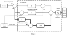
- FIG. 2 schematically shows a schematic structural diagram of a single-way PID control loop of a sixteen-way pneumatic fine-tuning mask deformation control subsystem 400 according to the embodiments of the present disclosure.
- the PLC controller subsystem 107 provides a sixteen-way PID controller for completing a mask deformation control.
- y is an output value of a PID algorithm and an output value in the system after calculation
- Kp is a proportional gain
- S is a Laplace operator
- b is a proportional action weight
- w is a set value
- x is a process value, i.e., an acting force d2etected by the force sensor
- c is a differential action weight
- TI is an differential action time
- TD is a differential action time.
- the sixteen-way pneumatic fine-tuning mask deformation control subsystem 400 further includes an air pressure output control subsystem.
- the air pressure output control subsystem includes: a sixteen-way cylinder and a sixteen-way electro-pneumatic proportional valve.
- the sixteen-way cylinder is connected with the sixteen-way electro-pneumatic proportional valve and configured to output the force deforming the mask.
- the sixteen-way electro-pneumatic proportional valve is connected with the analog output extension module and is configured to control an intensity of an output force of the sixteen-way cylinder according to the first control feedback quantity, thereby achieving a feedback control to the mask deformation.
- the PLC controller subsystem 107 is further configured to compare the air pressure in the connection air pipe acquired by the pressure sensor with a preset air pressure value, and generate a second control feedback quantity.
- the sixteen-way pneumatic fine-tuning mask deformation control subsystem 400 further includes a commutating solenoid valve configured to control a direction of the output force of the sixteen-way cylinder according to the second control feedback quantity.
- the PLC controller subsystem 107 is connected with the solenoid valve through an intermediate relay. In this way, the feedback control of the air pressure in the cylinder is achieved, and the precision of the mask deformation control is further improved.
- the PLC controller subsystem 107 is in communication with a host computer over an industrial Ethernet, and the PLC controller subsystem 107 controls a turning-on and off of the solenoid valve through the intermediate relay to achieve a push-out and retraction of the cylinder.
- the electro-pneumatic proportional valve is controlled through a voltage-type analog output signal to control the output air pressure, thereby controlling a cylinder force output. In this way, the mask force is controlled and the mask deformation is also controlled.
- a closed-loop effect is achieved through the cylinder output force voltage-type analog signal detected by the force sensor in combination with the PID controller inside the PLC controller subsystem 107.
- the alignment subsystem 200 includes: an eight-way image acquisition CCD camera, two image acquisition cards 104, an image processor 103, an image acquisition adjustment motor control subsystem 105, and an eight-way illuminating subsystem 300.
- Each way of the eight-way image acquisition CCD camera is provided with a telecentric lens for acquiring the images.
- Each of the two image acquisition cards 104 is configured to receive and transmit images acquired by four ways of the CCD camera.
- the image processor 103 is configured to preprocess the images, transmit the preprocessed images to a central control system, allow the central control system to judge whether the mask is aligned with the substrate according to the images, and generate a regulation instruction for aligning the mask with the substrate.
- the image acquisition adjustment motor control subsystem 105 is configured to adjust a position of the substrate according to the regulation instruction, so as to align the substrate with the mask.
- the eight-way illuminating subsystem 300 is configured to provide an illumination for the telecentric lens connected with each of the CCD cameras.
- the alignment subsystem 200 further includes: a compact linear displacement stage configured to adjust positions of the CCD cameras; and a multi-channel motion controller configured to move the compact linear displacement stage for a position adjustment according to the regulation instruction issued by the central control system.
- the system further includes a host computer 102, and a central control system is built in the host computer.
- the host computer 102 is configured to issue a program instruction to the PLC controller subsystem 107 according to an actual mask deformation control requirement.
- the program instruction is configured to generate the first control feedback quantity and regulate the sixteen-way cylinder of the sixteen-way pneumatic fine-tuning mask deformation control subsystem to adjust the deformation quantity of the mask.
- the host computer 102 is further configured to judge whether the mask is aligned with the substrate according to the images, generate a regulation instruction for aligning the mask with the substrate, and control a mechanical structure for adjusting the position of the substrate to align the substrate with the mask.
- the host computer 102 is in connection and communication with the sixteen-way pneumatic fine-tuning mask deformation control subsystem 400 through an industrial Ethernet bus, and the host computer 102 is in connection and communication with the alignment subsystem 200 through an industrial Ethernet bus, a PCIe bus or an RS232 serial portion communication bus.
- the image acquisition card 104 is in connection and communication with the host computer 102 through a PCIe X4 interface.
- the control by the host computer 102 achieves the feedback control of the mask deformation and the alignment system at the same time with simpler steps, economical costs, and fast reaction speed, thereby improving the alignment efficiency and the deformation control precision.
- an intelligent correction device control system for a super-resolution lithography precision mask including a sixteen-way pneumatic fine-tuning mask deformation control subsystem 400 and an alignment subsystem 200.
- the sixteen-way pneumatic fine-tuning mask deformation control subsystem 400 includes a mask force detection feedback subsystem, an air pressure output control subsystem, and a PID controller subsystem achieved by a PLC.
- the alignment subsystem 200 includes an eight-way image acquisition CCD, image acquisition cards 104, an image processor 103 and an eight-way illuminating subsystem 300.
- Image data acquired by the image acquisition CCD is transmitted to a high-performance host computer 102 through the image acquisition card 104, the host computer 102 preprocesses a related image through the image processor 103, and then makes a feedback to a central control system, so as to provide an image support for an alignment program.
- the eight-way illuminating subsystem 300 is connected with a phase modulator 106 through a signal generator to generate an excitation signal, so that a light emitted by a helium-neon laser provides an illumination for a telecentric lens connected with the CCD after modulation through a related optical path and an optical fiber transmission channel.
- FIG. 3 schematically shows a schematic diagram of an intelligent correction device control system for a super-resolution lithography precision mask according to the embodiments of the present disclosure.
- the intelligent correction device control system for a super-resolution lithography precision mask includes: a central control system 100, a control bus 101, a host computer 102, an image processor 103, an image acquisition card 104, a motor controller 105, a phase modulator 106, and a PLC controller subsystem 107.
- the image processor 103 is connected to the outside through a PCIe transmission channel 110; the image acquisition card 104 is connected to the outside through an Ethernet transmission channel 120; the motor controller 105 is connected to the outside through a serial port communication bus channel 130; the phase modulator 106 is connected to the outside through an optical fiber transmission channel 140; and the PLC controller subsystem 107 is connected to the outside through a digital and analog control channel 150.
- the host computer 120 of the control system is a high-performance industrial computer for an operation of an entire control system and a high-speed image processing calculation.
- a standard control bus is used as the control bus 101 of the system.
- the alignment subsystem 200 includes a multi-channel image acquisition subsystem, an image transmission subsystem, and an image processing subsystem, an image acquisition adjustment motor control subsystem 105 and an eight-way illuminating subsystem 300.
- the multi-channel image acquisition subsystem includes: an eight-way image acquisition CCD for image acquisition; and a telecentric lens for use in cooperation with the CCD.
- the image transmission subsystem includes an image acquisition card. 104.
- a single image acquisition card 104 is configured for a four-channel CCD acquisition data transmission.
- the image acquisition card 104 includes a trigger for an external triggering condition reception; an acquisition card internal system program for an operation application of the entire image acquisition card 104; a PHY transceiver for transmitting data to a PCIe interface, the data being received from an Ethernet interface and then processed through a system program; and four DDR RAMs for providing an internal storage for an internal program running.
- the image processing subsystem includes an image processor 103.
- the image processor uses an RTX 2080 SUPER graphics processing card of the NVIDIA company, and configured to comprehensively process data acquired and simply preprocessed by the image acquisition card 104, and finally transmit processed image data to the central control system.
- the image acquisition adjustment motor control subsystem 105 includes: a compact linear displacement stage for a CCD position adjustment; and a multi-channel motion controller for a motion control in cooperation with the compact linear displacement stage.
- the alignment subsystem 200 may use an industrial Ethernet bus based on a TCP/IP protocol or a customizable industrial Ethernet bus, a PCIe bus based on a PCIe X4 or a customizable PCIe bus, or an RS232 serial port communication bus based on a USRT or a customizable RS232 serial port communication bus.
- the alignment subsystem 200 is connected with the image processor 103 through the PCIe transmission channel 112 of the image processor 103, the alignment subsystem 200 is connected with the image acquisition card 104 through an eight-way CCD Ethernet transmission channel 122, and the alignment subsystem 200 is connected with the motor controller 105 through an eight-way motor controller serial port communication channel 132.
- the illuminating subsystem 300 is connected with the phase modulator 106 through an optical fiber transmission channel 143 of a helium-neon-laser phase modulation illuminating subsystem 300.
- the sixteen-way independent fine-tuning control subsystem 400 is connected with the PLC controller subsystem 107 through the force sensor and an analog transmission channel 154 of the electro-pneumatic proportional valve.
- the central control system 100 acquires a result of images processed by the image processor 103 by a central control program through the PCIe transmission channel 110, processes the images according to the actual requirements, judges an alignment based on the processed images, and performs a corresponding operation.
- the central control system 100 controls the motor to perform a displacement fine-tuning through the serial port communication bus channel 130 according to the actual requirements, so as to meet the working requirements.
- the central control system 100 is in communication with the PLC controller subsystem 107 over an industrial Ethernet based on a TCP/IP, and issues a control instruction to the PLC controller subsystem 107 according to an actual mask deformation control requirement, and related subsequent operations such as a slave computer control are performed by the PLC controller subsystem 107.
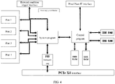
- FIG. 4 schematically shows a structural block diagram of an internal structure and channel of an image acquisition card 104 according to the embodiments of the present disclosure.
- FPGA chip XC3S4000-4FGG900C of XILINX Company is integrated in the image acquisition card 104, and an X4PCI Express ® second-generation interface is used to provide a total of 2GB/s bandwidth to achieve a data transmission between the image acquisition card 104 and the host computer 102.
- the image acquisition card 104 receives image information transmitted from the CCD Ethernet interface through four Ethernet ports.
- the control system in this embodiment of the present disclosure uses eight CCDs all together, and therefore two image acquisition cards 104 are used to achieve image transmission.
- the image acquisition card 104 is connected with the central control system 100 through the PCIe X4 interface, and performs related image processing through the image processor 103.
- this host computer 102 uses a dual-way Xeon E5 2620 V3 as a processor, and is configured with a 32GB RAM and a 256G SSD to ensure a high-speed operation of the system.
- System programs and control programs are integrated inside the image acquisition card 104. After image information received by ports 1-4 is preliminarily processed by the system programs, the PHY transceiver transmits the data to the host computer 102 through the PCIe X4 interface. 4 DDR RAMs are also integrated inside the image acquisition card 104 for program operation.
- the image processor 103 is an RTX 2080 SUPER high-performance graphics card, and data received by the image acquisition card 104 is transmitted to the image processor 103 through the PCIe transmission channel 110, so that the image processor 103 processes the data and transmits the data to the central control system 100.
- the image acquisition card 104 uses a XILINX XC3 S4000-4FGG900C FPGA chip as a processor, and a single image acquisition card 104 may acquire image data transmitted through four Ethernet transmission channels 122. In this way, a total of two image acquisition cards 104 are used to acquire CCD image data of eight channels.
- the motor controller 105 adjusts a position of a CCD image acquisition by controlling motion positions of eight compact linear displacement stages in cooperation with a manual displacement stage.
- the signal generator After a red light having a wavelength of 633nm generated by the helium-neon laser is collimated and focused, the signal generator generates an excitation signal, the phase modulator 106 modulates the excitation signal, and finally the light is output to the telecentric lens through the optical fiber transmission channel 140.
- the telecentric lens is connected with the CCD to provide an illumination for the CCD.
- a total of eight CCDs are used in the present disclosure to observe eight points at four sides of the mask.
- the sixteen-way pneumatic fine-tuning mask deformation control subsystem 400 further includes a PLC controller subsystem 107 and an analog input and output extension module, a PLC internal PID controller, a mask force detection feedback subsystem, and an air pressure output control subsystem.
- the PID controller provided by the PLC controller subsystem 107 is configured to complete a closed-loop control of a cylinder output force. After an actual PID debugging is performed to the apparatus mounted on site, when the cylinder output force, i.e., a force situation of the mask needs to be adjusted subsequently, the force situation detected by the force sensor and the air pressure output situation of the electro-pneumatic proportional valve are regulated through the internal PID controller to achieve the control purpose.
- a power supply system of the PLC controller subsystem 107 is provided by a DC24 power supply, and at the same time, the DC24 power supply also supplies power for the electro-pneumatic proportional valve, the force sensor, the pressure sensor, the solenoid valve and the like.
- the PLC controller subsystem 107 is additionally extended to include an analog output module configured to output a voltage signal controlled by the electro-pneumatic proportional valve, an analog input module configured to achieve a conversion of an analog voltage signal input by the force sensor and the pressure sensor, a digital output module configured to control other buttons, switches and intermediate relays, and a digital input module configured to get access to a digital feedback signal and including a cylinder piston push-out limit switch, etc.
- the PID controller provided by the PLC controller subsystem 107 is configured to complete a closed-loop control of a cylinder output force.
- a power supply system of the PLC controller subsystem 107 is provided by a DC24 power supply, and at the same time, the DC24 power supply also supplies power for the electro-pneumatic proportional valve, the force sensor, the pressure sensor, the solenoid valve and the like.
- the PLC of PLC controller subsystem 107 uses a Siemens S7-1200 CPU 1215C DC/DC/DC as the controller, and the CPU has an operation memory (integrated) of 100 kB, a loading memory (integrated) of 4MB, a keeping memory (integrated) of 10kB, an integrated digital I/O of 14 inputs/10 outputs, an integrated analog I/O of 2 inputs/2 outputs, and a process mapping area of 1024 bytes input/1024 bytes output.
- the basic data type length of the S7-1200 PLC reaches 32 bits.
- the S7-1200 PLC supports two pointer types: Pointer and Any, so that the S7-1200 has certain flexibility in programming.
- a Boolean execution speed is 0.08 ⁇ s/instruction
- a move word variable execution speed is 1.7 ⁇ s/instruction
- a floating point calculation execution speed is 2.3 ⁇ s/instruction.
- the sixteen-way pneumatic fine-tuning mask deformation control subsystem 400 uses an industrial Ethernet bus based on a TCP/IP protocol or a customizable industrial Ethernet bus.
- the eight-way illuminating subsystem 300 includes: a helium-neon laser configured to generate a light having a wavelength of 633nm; a focusing lens configured to focus a collimated light into an optical cable; a collimating lens configured to collimate an output light of the optical cable; an optical cable configured to transmit an optical signal; an adapter configured to connect an optical fiber end with a telecentric objective lens; a phase modulator 106 configured to modulate a related output optical signal; and a signal generator configured to generate an excitation signal of the phase modulator 106.
Landscapes
- Engineering & Computer Science (AREA)
- Physics & Mathematics (AREA)
- General Physics & Mathematics (AREA)
- Multimedia (AREA)
- Signal Processing (AREA)
- Quality & Reliability (AREA)
- Computer Vision & Pattern Recognition (AREA)
- Theoretical Computer Science (AREA)
- Automation & Control Theory (AREA)
- Exposure And Positioning Against Photoresist Photosensitive Materials (AREA)
Applications Claiming Priority (2)
| Application Number | Priority Date | Filing Date | Title |
|---|---|---|---|
| CN202010355155.2A CN111580359B (zh) | 2020-04-29 | 2020-04-29 | 一种用于超分辨光刻精密掩模的智能校正装置控制系统 |
| PCT/CN2021/090688 WO2021219030A1 (zh) | 2020-04-29 | 2021-04-28 | 一种用于超分辨光刻精密掩模的智能校正装置控制系统 |
Publications (4)
| Publication Number | Publication Date |
|---|---|
| EP4134750A1 true EP4134750A1 (de) | 2023-02-15 |
| EP4134750A4 EP4134750A4 (de) | 2023-09-20 |
| EP4134750B1 EP4134750B1 (de) | 2025-06-11 |
| EP4134750C0 EP4134750C0 (de) | 2025-06-11 |
Family
ID=72112442
Family Applications (1)
| Application Number | Title | Priority Date | Filing Date |
|---|---|---|---|
| EP21796326.3A Active EP4134750B1 (de) | 2020-04-29 | 2021-04-28 | Intelligentes korrekturvorrichtungssteuerungssystem für hochauflösende photolithographische präzisionsmaske |
Country Status (5)
| Country | Link |
|---|---|
| US (1) | US11714358B2 (de) |
| EP (1) | EP4134750B1 (de) |
| JP (1) | JP7431475B2 (de) |
| CN (1) | CN111580359B (de) |
| WO (1) | WO2021219030A1 (de) |
Families Citing this family (3)
| Publication number | Priority date | Publication date | Assignee | Title |
|---|---|---|---|---|
| CN111580359B (zh) * | 2020-04-29 | 2021-06-18 | 中国科学院光电技术研究所 | 一种用于超分辨光刻精密掩模的智能校正装置控制系统 |
| CN117420726A (zh) * | 2023-11-06 | 2024-01-19 | 中国科学院光电技术研究所 | 形变矫正装置 |
| CN119960275B (zh) * | 2025-04-10 | 2025-07-04 | 新毅东(北京)科技有限公司 | 一种用于掩模板的快速预对准装置及方法 |
Family Cites Families (25)
| Publication number | Priority date | Publication date | Assignee | Title |
|---|---|---|---|---|
| US4737824A (en) * | 1984-10-16 | 1988-04-12 | Canon Kabushiki Kaisha | Surface shape controlling device |
| US6549271B2 (en) * | 1997-01-28 | 2003-04-15 | Nikon Corporation | Exposure apparatus and method |
| US6261728B1 (en) * | 1998-10-19 | 2001-07-17 | Vanguard International Semiconductor Corporation | Mask image scanning exposure method |
| EP1111473A3 (de) * | 1999-12-23 | 2004-04-21 | ASML Netherlands B.V. | Lithographischer Apparat mit Vakuumkammer und interferometrischem Ausrichtungssystem |
| JP2001221279A (ja) * | 2000-02-09 | 2001-08-17 | Canon Inc | 能動制振装置 |
| JP4671473B2 (ja) * | 2000-07-14 | 2011-04-20 | ルネサスエレクトロニクス株式会社 | マスクデータ補正装置、転写用マスクの製造方法、および、パターン構造を有する装置の製造方法 |
| JP4046961B2 (ja) * | 2001-09-03 | 2008-02-13 | キヤノン株式会社 | 位置検出方法、位置検出装置、露光装置及び露光方法 |
| US7019816B2 (en) * | 2003-12-17 | 2006-03-28 | Asml Netherlands B.V. | Lithographic apparatus, device manufacturing method, and device manufactured thereby |
| US7125128B2 (en) * | 2004-01-26 | 2006-10-24 | Nikon Corporation | Adaptive-optics actuator arrays and methods for using such arrays |
| JP2007103657A (ja) | 2005-10-04 | 2007-04-19 | Canon Inc | 光学素子保持装置、露光装置およびデバイス製造方法 |
| JP4714033B2 (ja) | 2006-02-03 | 2011-06-29 | 株式会社オーク製作所 | マスク保持機構 |
| EP3267258A1 (de) * | 2006-02-21 | 2018-01-10 | Nikon Corporation | Belichtungsvorrichtung, belichtungsverfahren und verfahren zur herstellung einer vorrichtung |
| WO2008099795A2 (en) * | 2007-02-06 | 2008-08-21 | Canon Kabushiki Kaisha | Imprint method and imprint apparatus |
| CN101446777B (zh) * | 2008-12-30 | 2011-03-16 | 中国科学院光电技术研究所 | 一种超分辨i线光刻装置 |
| US8792078B2 (en) * | 2009-04-27 | 2014-07-29 | Taiwan Semiconductor Manufacturing Company, Ltd. | Method and pellicle mounting apparatus for reducing pellicle induced distortion |
| CN104570592B (zh) * | 2013-10-11 | 2019-04-30 | 上海微电子装备(集团)股份有限公司 | 一种大掩模版整形装置和方法 |
| JP6025178B2 (ja) * | 2013-11-11 | 2016-11-16 | 信越化学工業株式会社 | ペリクルの貼り付け方法及びこの方法に用いる貼り付け装置 |
| CN104635427B (zh) * | 2013-11-14 | 2018-07-20 | 上海微电子装备(集团)股份有限公司 | 用于光刻设备的掩模整形装置及掩模整形方法 |
| JP6371576B2 (ja) * | 2014-05-02 | 2018-08-08 | キヤノン株式会社 | 光学装置、投影光学系、露光装置、および物品の製造方法 |
| JP2017059717A (ja) * | 2015-09-17 | 2017-03-23 | 株式会社東芝 | テンプレート、インプリント装置および制御方法 |
| CN106933024B (zh) * | 2015-12-30 | 2020-05-01 | 上海微电子装备(集团)股份有限公司 | 一种可检测掩膜弯曲度的光刻系统及检测方法 |
| CN107329374B (zh) * | 2016-04-29 | 2019-06-25 | 上海微电子装备(集团)股份有限公司 | 掩模版弯曲补偿装置、检测补偿系统及补偿方法 |
| CN107817653B (zh) * | 2017-12-12 | 2019-10-08 | 中国科学院光电技术研究所 | 基于柔性材料的超分辨光刻装置 |
| CN108089409B (zh) * | 2017-12-15 | 2019-10-08 | 中国科学院光电技术研究所 | 一种大面积超分辨光刻装置 |
| CN111580359B (zh) * | 2020-04-29 | 2021-06-18 | 中国科学院光电技术研究所 | 一种用于超分辨光刻精密掩模的智能校正装置控制系统 |
-
2020
- 2020-04-29 CN CN202010355155.2A patent/CN111580359B/zh active Active
-
2021
- 2021-04-28 WO PCT/CN2021/090688 patent/WO2021219030A1/zh not_active Ceased
- 2021-04-28 US US17/997,189 patent/US11714358B2/en active Active
- 2021-04-28 EP EP21796326.3A patent/EP4134750B1/de active Active
- 2021-04-28 JP JP2022565880A patent/JP7431475B2/ja active Active
Also Published As
| Publication number | Publication date |
|---|---|
| EP4134750B1 (de) | 2025-06-11 |
| CN111580359A (zh) | 2020-08-25 |
| JP7431475B2 (ja) | 2024-02-15 |
| EP4134750A4 (de) | 2023-09-20 |
| US20230126995A1 (en) | 2023-04-27 |
| WO2021219030A1 (zh) | 2021-11-04 |
| JP2023515713A (ja) | 2023-04-13 |
| CN111580359B (zh) | 2021-06-18 |
| EP4134750C0 (de) | 2025-06-11 |
| US11714358B2 (en) | 2023-08-01 |
Similar Documents
| Publication | Publication Date | Title |
|---|---|---|
| EP4134750A1 (de) | Intelligentes korrekturvorrichtungssteuerungssystem für hochauflösende photolithographische präzisionsmaske | |
| US10976723B2 (en) | Motion control system | |
| CN101410767B (zh) | 用于阀组的调节器模块 | |
| CN106735865A (zh) | 一种基于闭环控制的超快激光加工系统及方法 | |
| CN107945159B (zh) | 一种光纤几何参数和衰减系数集成测试的自动化控制系统 | |
| CN102621008B (zh) | 全自动应变控制式直剪测试仪器及其用途 | |
| CN104360689A (zh) | 攻角机构角度控制系统 | |
| CN108687776A (zh) | 一种机器人控制系统 | |
| CN113334373B (zh) | 变电站室内自动巡检机器人系统控制方法 | |
| CN116795045A (zh) | 一种基于zynq的数控折弯机控制装置及方法 | |
| CN112449162B (zh) | 利用智能终端对激光异物清除设备进行控制的方法与装置 | |
| CN111478631A (zh) | 一种用于贴片机的音圈电机控制系统及控制方法 | |
| CN118299908A (zh) | 一种光纤激光器控制系统和驱动电路 | |
| CN209133292U (zh) | 一种贴片电阻激光调阻系统 | |
| CN208239889U (zh) | 一种用于探测及三维空间图像重构的智能车控制系统 | |
| CN1129019C (zh) | 大型天文望远镜中力促动器的电控系统 | |
| EP3289308B1 (de) | Tischvorrichtung, verfahren zur steuerung einer tischvorrichtung und mikrokopsystem | |
| CN1862436A (zh) | 基于dsp的快速反射镜实时主动振动控制系统 | |
| CN214007154U (zh) | 一种微型顶管机的高精度导向系统 | |
| CN202019338U (zh) | 一种马达驱动器 | |
| CN105373168A (zh) | 高精度发射平台转换装置控制系统及控制方法 | |
| CN207027519U (zh) | 用于电力负载箱校准的机械档位旋钮自适应装置 | |
| CN104834321A (zh) | 高加速气悬浮系统的精确定位控制器及其控制方法 | |
| KR100905023B1 (ko) | 고전압 다축 서보 제어시스템 | |
| CN218450151U (zh) | 一种无人驾驶车辆双核心云网关装置 |
Legal Events
| Date | Code | Title | Description |
|---|---|---|---|
| STAA | Information on the status of an ep patent application or granted ep patent |
Free format text: STATUS: THE INTERNATIONAL PUBLICATION HAS BEEN MADE |
|
| PUAI | Public reference made under article 153(3) epc to a published international application that has entered the european phase |
Free format text: ORIGINAL CODE: 0009012 |
|
| STAA | Information on the status of an ep patent application or granted ep patent |
Free format text: STATUS: REQUEST FOR EXAMINATION WAS MADE |
|
| 17P | Request for examination filed |
Effective date: 20221108 |
|
| AK | Designated contracting states |
Kind code of ref document: A1 Designated state(s): AL AT BE BG CH CY CZ DE DK EE ES FI FR GB GR HR HU IE IS IT LI LT LU LV MC MK MT NL NO PL PT RO RS SE SI SK SM TR |
|
| DAV | Request for validation of the european patent (deleted) | ||
| DAX | Request for extension of the european patent (deleted) | ||
| A4 | Supplementary search report drawn up and despatched |
Effective date: 20230821 |
|
| RIC1 | Information provided on ipc code assigned before grant |
Ipc: G03F 7/00 20060101ALI20230814BHEP Ipc: G03F 7/20 20060101ALI20230814BHEP Ipc: G03F 9/00 20060101AFI20230814BHEP |
|
| GRAP | Despatch of communication of intention to grant a patent |
Free format text: ORIGINAL CODE: EPIDOSNIGR1 |
|
| STAA | Information on the status of an ep patent application or granted ep patent |
Free format text: STATUS: GRANT OF PATENT IS INTENDED |
|
| RIC1 | Information provided on ipc code assigned before grant |
Ipc: G03F 7/20 20060101ALI20250303BHEP Ipc: G03F 9/00 20060101AFI20250303BHEP |
|
| INTG | Intention to grant announced |
Effective date: 20250313 |
|
| GRAS | Grant fee paid |
Free format text: ORIGINAL CODE: EPIDOSNIGR3 |
|
| GRAA | (expected) grant |
Free format text: ORIGINAL CODE: 0009210 |
|
| STAA | Information on the status of an ep patent application or granted ep patent |
Free format text: STATUS: THE PATENT HAS BEEN GRANTED |
|
| AK | Designated contracting states |
Kind code of ref document: B1 Designated state(s): AL AT BE BG CH CY CZ DE DK EE ES FI FR GB GR HR HU IE IS IT LI LT LU LV MC MK MT NL NO PL PT RO RS SE SI SK SM TR |
|
| REG | Reference to a national code |
Ref country code: GB Ref legal event code: FG4D |
|
| REG | Reference to a national code |
Ref country code: CH Ref legal event code: EP |
|
| REG | Reference to a national code |
Ref country code: IE Ref legal event code: FG4D |
|
| REG | Reference to a national code |
Ref country code: DE Ref legal event code: R096 Ref document number: 602021032204 Country of ref document: DE |
|
| U01 | Request for unitary effect filed |
Effective date: 20250701 |
|
| U07 | Unitary effect registered |
Designated state(s): AT BE BG DE DK EE FI FR IT LT LU LV MT NL PT RO SE SI Effective date: 20250707 |
|
| PG25 | Lapsed in a contracting state [announced via postgrant information from national office to epo] |
Ref country code: ES Free format text: LAPSE BECAUSE OF FAILURE TO SUBMIT A TRANSLATION OF THE DESCRIPTION OR TO PAY THE FEE WITHIN THE PRESCRIBED TIME-LIMIT Effective date: 20250611 |
|
| PG25 | Lapsed in a contracting state [announced via postgrant information from national office to epo] |
Ref country code: NO Free format text: LAPSE BECAUSE OF FAILURE TO SUBMIT A TRANSLATION OF THE DESCRIPTION OR TO PAY THE FEE WITHIN THE PRESCRIBED TIME-LIMIT Effective date: 20250911 Ref country code: GR Free format text: LAPSE BECAUSE OF FAILURE TO SUBMIT A TRANSLATION OF THE DESCRIPTION OR TO PAY THE FEE WITHIN THE PRESCRIBED TIME-LIMIT Effective date: 20250912 |
|
| PG25 | Lapsed in a contracting state [announced via postgrant information from national office to epo] |
Ref country code: HR Free format text: LAPSE BECAUSE OF FAILURE TO SUBMIT A TRANSLATION OF THE DESCRIPTION OR TO PAY THE FEE WITHIN THE PRESCRIBED TIME-LIMIT Effective date: 20250611 |
|
| PG25 | Lapsed in a contracting state [announced via postgrant information from national office to epo] |
Ref country code: RS Free format text: LAPSE BECAUSE OF FAILURE TO SUBMIT A TRANSLATION OF THE DESCRIPTION OR TO PAY THE FEE WITHIN THE PRESCRIBED TIME-LIMIT Effective date: 20250911 |
|
| PG25 | Lapsed in a contracting state [announced via postgrant information from national office to epo] |
Ref country code: IS Free format text: LAPSE BECAUSE OF FAILURE TO SUBMIT A TRANSLATION OF THE DESCRIPTION OR TO PAY THE FEE WITHIN THE PRESCRIBED TIME-LIMIT Effective date: 20251011 |
|
| PG25 | Lapsed in a contracting state [announced via postgrant information from national office to epo] |
Ref country code: SM Free format text: LAPSE BECAUSE OF FAILURE TO SUBMIT A TRANSLATION OF THE DESCRIPTION OR TO PAY THE FEE WITHIN THE PRESCRIBED TIME-LIMIT Effective date: 20250611 |
|
| PG25 | Lapsed in a contracting state [announced via postgrant information from national office to epo] |
Ref country code: CZ Free format text: LAPSE BECAUSE OF FAILURE TO SUBMIT A TRANSLATION OF THE DESCRIPTION OR TO PAY THE FEE WITHIN THE PRESCRIBED TIME-LIMIT Effective date: 20250611 |
|
| PG25 | Lapsed in a contracting state [announced via postgrant information from national office to epo] |
Ref country code: PL Free format text: LAPSE BECAUSE OF FAILURE TO SUBMIT A TRANSLATION OF THE DESCRIPTION OR TO PAY THE FEE WITHIN THE PRESCRIBED TIME-LIMIT Effective date: 20250611 |
|
| PG25 | Lapsed in a contracting state [announced via postgrant information from national office to epo] |
Ref country code: SK Free format text: LAPSE BECAUSE OF FAILURE TO SUBMIT A TRANSLATION OF THE DESCRIPTION OR TO PAY THE FEE WITHIN THE PRESCRIBED TIME-LIMIT Effective date: 20250611 |
|
| PLBE | No opposition filed within time limit |
Free format text: ORIGINAL CODE: 0009261 |
|
| STAA | Information on the status of an ep patent application or granted ep patent |
Free format text: STATUS: NO OPPOSITION FILED WITHIN TIME LIMIT |
|
| REG | Reference to a national code |
Ref country code: CH Ref legal event code: L10 Free format text: ST27 STATUS EVENT CODE: U-0-0-L10-L00 (AS PROVIDED BY THE NATIONAL OFFICE) Effective date: 20260423 |